EP2910290A1 - Filtre à liquide - Google Patents
Filtre à liquide Download PDFInfo
- Publication number
- EP2910290A1 EP2910290A1 EP14196222.5A EP14196222A EP2910290A1 EP 2910290 A1 EP2910290 A1 EP 2910290A1 EP 14196222 A EP14196222 A EP 14196222A EP 2910290 A1 EP2910290 A1 EP 2910290A1
- Authority
- EP
- European Patent Office
- Prior art keywords
- filter element
- end plate
- liquid filter
- filter according
- housing
- Prior art date
- Legal status (The legal status is an assumption and is not a legal conclusion. Google has not performed a legal analysis and makes no representation as to the accuracy of the status listed.)
- Granted
Links
- 239000007788 liquid Substances 0.000 title claims abstract description 19
- XLYOFNOQVPJJNP-UHFFFAOYSA-N water Substances O XLYOFNOQVPJJNP-UHFFFAOYSA-N 0.000 claims abstract description 34
- 239000012530 fluid Substances 0.000 claims description 11
- 238000007789 sealing Methods 0.000 claims description 7
- 239000000446 fuel Substances 0.000 claims description 5
- 238000003466 welding Methods 0.000 description 4
- 239000000463 material Substances 0.000 description 3
- 238000000926 separation method Methods 0.000 description 3
- 238000004026 adhesive bonding Methods 0.000 description 2
- 239000002283 diesel fuel Substances 0.000 description 2
- 238000004519 manufacturing process Methods 0.000 description 2
- 230000001427 coherent effect Effects 0.000 description 1
- 230000001419 dependent effect Effects 0.000 description 1
- 238000013461 design Methods 0.000 description 1
- 238000011161 development Methods 0.000 description 1
- 230000018109 developmental process Effects 0.000 description 1
- 238000001914 filtration Methods 0.000 description 1
- 238000012423 maintenance Methods 0.000 description 1
- 238000000034 method Methods 0.000 description 1
- 239000007787 solid Substances 0.000 description 1
- 238000012546 transfer Methods 0.000 description 1
- 230000007704 transition Effects 0.000 description 1
Images
Classifications
-
- B—PERFORMING OPERATIONS; TRANSPORTING
- B01—PHYSICAL OR CHEMICAL PROCESSES OR APPARATUS IN GENERAL
- B01D—SEPARATION
- B01D29/00—Filters with filtering elements stationary during filtration, e.g. pressure or suction filters, not covered by groups B01D24/00 - B01D27/00; Filtering elements therefor
- B01D29/96—Filters with filtering elements stationary during filtration, e.g. pressure or suction filters, not covered by groups B01D24/00 - B01D27/00; Filtering elements therefor in which the filtering elements are moved between filtering operations; Particular measures for removing or replacing the filtering elements; Transport systems for filters
-
- B—PERFORMING OPERATIONS; TRANSPORTING
- B01—PHYSICAL OR CHEMICAL PROCESSES OR APPARATUS IN GENERAL
- B01D—SEPARATION
- B01D36/00—Filter circuits or combinations of filters with other separating devices
- B01D36/003—Filters in combination with devices for the removal of liquids
-
- B—PERFORMING OPERATIONS; TRANSPORTING
- B01—PHYSICAL OR CHEMICAL PROCESSES OR APPARATUS IN GENERAL
- B01D—SEPARATION
- B01D2201/00—Details relating to filtering apparatus
- B01D2201/29—Filter cartridge constructions
- B01D2201/291—End caps
- B01D2201/295—End caps with projections extending in a radial outward direction, e.g. for use as a guide, spacing means
-
- B—PERFORMING OPERATIONS; TRANSPORTING
- B01—PHYSICAL OR CHEMICAL PROCESSES OR APPARATUS IN GENERAL
- B01D—SEPARATION
- B01D2201/00—Details relating to filtering apparatus
- B01D2201/34—Seals or gaskets for filtering elements
- B01D2201/342—Axial sealings
Definitions
- the invention relates to a liquid filter, in particular a fuel or oil filter, according to the preamble of claim 1.
- a liquid filter is described with a hollow cylindrical, to be flowed through radially filter element whose end faces are bordered by end plates.
- the discharge of the purified fluid takes place axially over the inner cavity, which is connected to a drain pipe.
- a sealing ring is inserted, which is arranged between the filter element and the outflow pipe.
- a diesel fuel filter system including an annular filter element in a filter housing supported on a riser will be described. Axially offset from the filter element, a coalescing element is arranged on the riser, via which the water droplets dispersively present in the fuel are enriched to form larger droplets, in order to facilitate water separation.
- the water droplets in the fuel are deposited on the radially outer side of the coalescing element and flow on the outside of the filter element axially down to a located in the bottom of the housing water collection chamber from which the water can be drained via a drain plug.
- the invention is based on the object with simple constructive measures to perform a liquid filter in such a way that a bottom-side water collection chamber is flow-tight separated from an overlying filter element.
- the liquid filter according to the invention can be used for example for the filtration of fuel or oil and has a hollow cylindrical filter element in a housing component, which is flowed through radially by the fluid to be cleaned.
- the direction of flow preferably takes place radially from outside to inside, so that the radially outer lateral surface forms the raw side and the cylindrical cavity located in the filter element forms the clean side.
- a water collection chamber in which water droplets, which are separated from the fluid, are collected.
- the hollow cylindrical filter element has at its two opposite, axial end faces in each case an end disk, which close the filter element axially fluid-tight.
- end plates In the end plates centric openings are introduced, can be derived via the fluid from the cavity.
- the bottom lying, the bottom-facing end plate of the filter element is located directly on the inside of the housing component and closes the arranged under the end plate, bottom-side water collection space from fluid-tight, preferably with respect to the raw side of the filter element.
- This embodiment has the advantage that the sealing and sealing can be accomplished in a structurally simple manner; a sealing element between the end plate of the filter element and the inside of the housing component is not required. Rather, the end plate is directly and fluid-tight against the inside of the housing component.
- the radially outer edge of the end plate is fluid-tight against the housing component.
- the raw side In a flow through the hollow cylindrical filter element radially from outside to inside the outside forms the raw side, which is completed via the flow-tight connection between the lower, radially outer edge of the end plate and the inner edge of the housing member fluidly against the underlying water collecting space. A transfer of raw fluid to the water collection is excluded.
- the separation of the water takes place in the liquid filter preferably on the clean side of the filter element.
- a coalescing element on the clean side of the filter element and thus in the interior cavity.
- the coalescing element ensures an enrichment of dispersively present water droplets to form larger droplets, which can then flow axially downwards into the water collecting space via the inner cavity.
- the discharge of the purified fluid takes place advantageously from the cavity axially upwards.
- a water separation screen can also be arranged on the clean side of the filter element.
- the coalescing element is located between the clean side of the filter element and the Wasserabscheidesieb, which is preferably arranged in the inner cavity.
- connection between the end plate of the filter element and the inside of the housing component is preferably carried out in a non-detachable manner.
- the end plate may be welded to the housing component, for example by means of a rotary vibration welding.
- a different type of fixed connection for example gluing.
- Due to the non-detachable connection the filter element and the housing component form a coherent structural unit which is to be connected overall to a female housing.
- the housing component with the filter element forms, for example, a cover with an external thread, which can be screwed into a corresponding thread on a receiving housing. For maintenance purposes, only the assembly comprising the housing member and the filter element, must be unscrewed from the female housing and replaced by another assembly.
- the end plate of the filter element and the inside of the housing component can be connected to one another via a tongue-and-groove connection. It is a positive engagement of the circumferential projection in the circumferential groove, wherein at the same time a kind of labyrinth seal between the water collection chamber and the overlying raw side is given to the filter element.
- the projection is advantageously flat in the groove, wherein projection and groove, for example, have a trapezoidal cross-section with each other at an angle Sidewalls and a straight-sided front. The flat contact between the inner walls of the groove and the outer walls of the projection, the tightness is supported.
- curved surfaces may also be considered, for example convexly curved side surfaces on the projection and correspondingly shaped inner walls on the groove.
- the circumferential design of groove and projection also has the advantage that in a simple manner a welded joint can be produced by rotary vibration welding.
- Both the end plate and the housing component are each made of materials that support a flow-tight connection and are particularly suitable for the production of a welded joint.
- the housing component made of a plastic material and also the end plate of a welding process favoring plastic material.
- a liquid filter such as a diesel fuel filter.
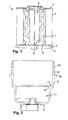
- Fig. 1 is the hollow cylindrical filter element 1 is shown, the filter medium or medium body 2 at both opposite axial end faces of each end plate 3, 4 is closed flow-tight.
- each end plate 3, 4 is a central recess for the outflow of purified fluid upwards or deposited water droplets down from an inner, cylindrical cavity 5 is introduced in the filter element.
- the filter element 1 is flowed through radially from the outside to the inside by the fluid to be cleaned, so that the outer lateral surface form the crude side and the inner, cylindrical cavity 5 the clean side.
- the cavity 5 is lined by a support or central tube 6, which gives the filter medium body 2 additional stability. Between the outflow side of the filter medium body 2 and the central tube 6 there is a circulating coalescing element 7, with which small water droplets dispersively present in the fluid are brought together to form larger drops of water.
- a Wasserabscheidesieb 8 is also integrated within the center tube 6.
- the water droplets can flow down and flow through the opening in the lower end plate 4 axially downwards in the direction of a water collecting space.
- the purified fluid is discharged axially from the cavity 5 via the opening in the upper end disk 3.
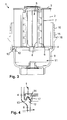
- a housing member 9 is shown, the filter element 1 from Fig. 1 receives.
- the housing member 9 forms a lid with an external thread 10 and can be screwed into a female housing from below.
- the ground-level area inside the housing 9 forms a water collection chamber 11 for receiving water, which is deposited in the filter element 1 and drips down.
- the housing member 9 is formed approximately pot-shaped, wherein the ground-level area with the water collection chamber 11 has a smaller diameter than the upper, the open end adjacent area in which the filter element 1 is used.
- a circumferential, radially inwardly projecting shoulder 12 is formed, on which adjacent to the housing wall, a circumferential connecting projection 13 is arranged, which is directed relative to the longitudinal axis of the filter element 1 and housing member 9 axially upwards.
- the connecting projection 13 is assigned to the lower end plate 4 of the filter element 1, a likewise circumferential connecting groove 14 which is formed axially downwardly open and has the same cross-sectional shape as the connecting projection 13 on the inside of the housing member 9.
- the filter element 1 can be placed with the connection groove 14 on the underside of the lower end plate 4 in a form-fitting manner on the connection projection 13 on the inside of the housing component 9 ( Fig. 3, 4 ).
- This allows the production of a solid, permanent connection between the filter element 1 and the housing member 9 by the connecting projection 13 and the connecting groove 14 are connected to each other, for example by rotary friction or vibration welding.
- other types of fixed connections are also possible, for example gluing.
- connection is fluid-tight, so that the water collection chamber 11 is separated in the near-bottom region of the housing member 9 from the raw side on the outer circumference of the filter element 1.
- the water collection chamber 9 only communicates with the cavity 5 in the filter element 1, ie with the clean side, from which water droplets 8 can drain water droplets downwards in the direction of the water collection chamber 11.
- Fig. 2 and Fig. 3 can be seen running on the outside of the housing member 9 immediately below the external thread 10 a receiving groove 15 which lies above a circumferential, radially outwardly directed shoulder 16 and serves to receive a sealing ring.
- the shoulder 16 limits the depth of engagement.
- the connecting projection 13 on the inside of the housing member 9 and the connecting groove 14 on the underside of the end plate 4 each have a trapezoidal, equal cross-section.
- a circumferential shoulder 17 is formed both on the inside of the housing component 9 and on the underside of the end disk 4, against which the corresponding sides lie flat against one another.
- the paragraph 17 extends the connecting surface between the inside of the housing member 9 and the end plate 4, whereby the tightness is further improved.
Applications Claiming Priority (1)
| Application Number | Priority Date | Filing Date | Title |
|---|---|---|---|
| DE102014000716.2A DE102014000716A1 (de) | 2014-01-23 | 2014-01-23 | Flüssigkeitsfilter |
Publications (2)
| Publication Number | Publication Date |
|---|---|
| EP2910290A1 true EP2910290A1 (fr) | 2015-08-26 |
| EP2910290B1 EP2910290B1 (fr) | 2020-02-05 |
Family
ID=52598541
Family Applications (1)
| Application Number | Title | Priority Date | Filing Date |
|---|---|---|---|
| EP14196222.5A Active EP2910290B1 (fr) | 2014-01-23 | 2014-12-04 | Filtre à liquide |
Country Status (3)
| Country | Link |
|---|---|
| EP (1) | EP2910290B1 (fr) |
| CN (1) | CN104801086A (fr) |
| DE (1) | DE102014000716A1 (fr) |
Cited By (1)
| Publication number | Priority date | Publication date | Assignee | Title |
|---|---|---|---|---|
| WO2020126709A1 (fr) * | 2018-12-21 | 2020-06-25 | Hengst Se | Cartouche filtrante pour un filtre à carburant avec filtration à trois étages |
Families Citing this family (3)
| Publication number | Priority date | Publication date | Assignee | Title |
|---|---|---|---|---|
| CN105688493A (zh) * | 2016-04-19 | 2016-06-22 | 苏州逸新和电子有限公司 | 一种密度可变的过滤网 |
| DE102018201740A1 (de) * | 2018-02-05 | 2019-08-08 | Mahle International Gmbh | Flüssigfiltereinrichtung |
| EP4313355A1 (fr) * | 2021-03-30 | 2024-02-07 | Donaldson Company, Inc. | Agencement de cartouche de filtre à bol ayant un piège et procédés |
Citations (4)
| Publication number | Priority date | Publication date | Assignee | Title |
|---|---|---|---|---|
| WO2001072396A1 (fr) * | 2000-03-24 | 2001-10-04 | Sogefi Filtration S.P.A | Filtre pour carburant de moteur diesel |
| EP0811411B1 (fr) | 1996-06-05 | 2003-03-19 | Fleetguard, Inc. | Elément filtrant remplaçable et ensemble filtre et couvercle encliquetable |
| WO2004082804A1 (fr) | 2003-03-21 | 2004-09-30 | Mann+Hummel Gmbh | Systeme de filtre a carburant |
| US20100101993A1 (en) * | 2008-10-27 | 2010-04-29 | Cummins Filtration Ip Inc. | Filter cartridge having a filter within a filter, and an endplate sealing structure on an outer filter element |
Family Cites Families (8)
| Publication number | Priority date | Publication date | Assignee | Title |
|---|---|---|---|---|
| CA678486A (en) * | 1964-01-21 | S. Hitzelberger William | Full-flow filtration unit | |
| US4036616A (en) * | 1974-05-01 | 1977-07-19 | Robert A. Baker | Bacteria filter and method of assembling same |
| ITRE20050139A1 (it) * | 2005-12-13 | 2007-06-14 | Ufi Filters Spa | Filtro per carburante diesel con riscaldatore |
| DE102006051406A1 (de) * | 2006-10-27 | 2008-04-30 | Mann + Hummel Gmbh | Kraftstofffilter |
| CN201510799U (zh) * | 2008-12-05 | 2010-06-23 | 康明斯过滤Ip公司 | 滤筒和组装结构 |
| KR20110062104A (ko) * | 2009-12-02 | 2011-06-10 | 현대자동차주식회사 | 디젤연료필터 |
| EP2542323B1 (fr) * | 2010-03-04 | 2018-09-05 | Hydac Filtertechnik Gmbh | Dispositif de filtration |
| CN102116236B (zh) * | 2011-02-15 | 2013-08-14 | 南充市攀峰滤清器有限公司 | 无公害双级油水分离柴油滤清器 |
-
2014
- 2014-01-23 DE DE102014000716.2A patent/DE102014000716A1/de not_active Ceased
- 2014-12-04 EP EP14196222.5A patent/EP2910290B1/fr active Active
-
2015
- 2015-01-23 CN CN201510034508.8A patent/CN104801086A/zh active Pending
Patent Citations (4)
| Publication number | Priority date | Publication date | Assignee | Title |
|---|---|---|---|---|
| EP0811411B1 (fr) | 1996-06-05 | 2003-03-19 | Fleetguard, Inc. | Elément filtrant remplaçable et ensemble filtre et couvercle encliquetable |
| WO2001072396A1 (fr) * | 2000-03-24 | 2001-10-04 | Sogefi Filtration S.P.A | Filtre pour carburant de moteur diesel |
| WO2004082804A1 (fr) | 2003-03-21 | 2004-09-30 | Mann+Hummel Gmbh | Systeme de filtre a carburant |
| US20100101993A1 (en) * | 2008-10-27 | 2010-04-29 | Cummins Filtration Ip Inc. | Filter cartridge having a filter within a filter, and an endplate sealing structure on an outer filter element |
Cited By (1)
| Publication number | Priority date | Publication date | Assignee | Title |
|---|---|---|---|---|
| WO2020126709A1 (fr) * | 2018-12-21 | 2020-06-25 | Hengst Se | Cartouche filtrante pour un filtre à carburant avec filtration à trois étages |
Also Published As
| Publication number | Publication date |
|---|---|
| CN104801086A (zh) | 2015-07-29 |
| EP2910290B1 (fr) | 2020-02-05 |
| DE102014000716A1 (de) | 2015-07-23 |
Similar Documents
| Publication | Publication Date | Title |
|---|---|---|
| EP3185982B1 (fr) | Dispositif de purification d'un liquide ou un gas et dispositif de separation | |
| EP1593419B1 (fr) | Elément filtrant et filtre à liquide pour fluides susceptibles de geler et méthode de fabrication dudit élément filtrant | |
| EP3271043B1 (fr) | Dispositif filtrant | |
| DE102013012918B4 (de) | Flüssigkeitsfilter und Filterelement, insbesondere für Kraftstoff | |
| DE102015007692A1 (de) | Filterelement | |
| WO2014082762A1 (fr) | Filtre, élément filtrant, boîtier de filtre et dispositif de purge d'un filtre | |
| EP2910290B1 (fr) | Filtre à liquide | |
| DE102012209242A1 (de) | Filtereinrichtung | |
| DE102016012327A1 (de) | Rundfilterelement, insbesondere zur Gasfiltration | |
| DE102013202446A1 (de) | Filteranordnung, insbesondere Ölfilteranordnung | |
| EP2283910A1 (fr) | Filtre à liquide, notamment filtre à huile | |
| WO2015018779A1 (fr) | Crible séparateur d'eau pour un élément filtrant dans un filtre de liquide | |
| EP3067102B1 (fr) | Separateur d'eau et systeme de separation d'eau comprenant un dispositif d'evacuation d'eau integre | |
| DE102009015094B4 (de) | Filterelement und Fluidfiltermodul | |
| WO2015082117A1 (fr) | Dispositif de filtrage avec adaptateur | |
| EP2653675A1 (fr) | Filtre à huile d'un moteur à combustion interne et élément de filtre à huile d'un filtre à huile | |
| DE102008020223A1 (de) | Flüssigkeitsfilter, insbesondere für Kraftstoff | |
| WO2016008605A1 (fr) | Dispositif de filtration d'huile, couvercle de boîtier et pot de boîtier d'un dispositif de filtration d'huile | |
| DE102009048588A1 (de) | Filtereinrichtung, insbesondere zur Flüssigkeitsfilterung in Brennkraftmaschinen | |
| EP3095500B1 (fr) | Systeme de filtre-reducteur de pression | |
| EP3261743B1 (fr) | Moyen de filtrage terminal à symétrie de révolution avec corps de support | |
| DE102013018199B4 (de) | Flüssigkeitsfilter, insbesondere für Kraftstoff | |
| DE102012007627B4 (de) | Filterelement | |
| DE102014010007B4 (de) | Filtervorrichtung und Filterelemente | |
| EP3452204A1 (fr) | Élément filtrant annulaire, en particulier pour la filtration de gaz, et dispositif de filtration |
Legal Events
| Date | Code | Title | Description |
|---|---|---|---|
| PUAI | Public reference made under article 153(3) epc to a published international application that has entered the european phase |
Free format text: ORIGINAL CODE: 0009012 |
|
| AK | Designated contracting states |
Kind code of ref document: A1 Designated state(s): AL AT BE BG CH CY CZ DE DK EE ES FI FR GB GR HR HU IE IS IT LI LT LU LV MC MK MT NL NO PL PT RO RS SE SI SK SM TR |
|
| AX | Request for extension of the european patent |
Extension state: BA ME |
|
| 17P | Request for examination filed |
Effective date: 20160224 |
|
| RBV | Designated contracting states (corrected) |
Designated state(s): AL AT BE BG CH CY CZ DE DK EE ES FI FR GB GR HR HU IE IS IT LI LT LU LV MC MK MT NL NO PL PT RO RS SE SI SK SM TR |
|
| STAA | Information on the status of an ep patent application or granted ep patent |
Free format text: STATUS: EXAMINATION IS IN PROGRESS |
|
| 17Q | First examination report despatched |
Effective date: 20170914 |
|
| GRAP | Despatch of communication of intention to grant a patent |
Free format text: ORIGINAL CODE: EPIDOSNIGR1 |
|
| STAA | Information on the status of an ep patent application or granted ep patent |
Free format text: STATUS: GRANT OF PATENT IS INTENDED |
|
| INTG | Intention to grant announced |
Effective date: 20190222 |
|
| GRAS | Grant fee paid |
Free format text: ORIGINAL CODE: EPIDOSNIGR3 |
|
| GRAJ | Information related to disapproval of communication of intention to grant by the applicant or resumption of examination proceedings by the epo deleted |
Free format text: ORIGINAL CODE: EPIDOSDIGR1 |
|
| GRAL | Information related to payment of fee for publishing/printing deleted |
Free format text: ORIGINAL CODE: EPIDOSDIGR3 |
|
| STAA | Information on the status of an ep patent application or granted ep patent |
Free format text: STATUS: EXAMINATION IS IN PROGRESS |
|
| INTC | Intention to grant announced (deleted) | ||
| RAP1 | Party data changed (applicant data changed or rights of an application transferred) |
Owner name: MANN + HUMMEL GMBH |
|
| RIN1 | Information on inventor provided before grant (corrected) |
Inventor name: AMMERSDOERFER, MICHA |
|
| GRAP | Despatch of communication of intention to grant a patent |
Free format text: ORIGINAL CODE: EPIDOSNIGR1 |
|
| STAA | Information on the status of an ep patent application or granted ep patent |
Free format text: STATUS: GRANT OF PATENT IS INTENDED |
|
| INTG | Intention to grant announced |
Effective date: 20190918 |
|
| GRAA | (expected) grant |
Free format text: ORIGINAL CODE: 0009210 |
|
| STAA | Information on the status of an ep patent application or granted ep patent |
Free format text: STATUS: THE PATENT HAS BEEN GRANTED |
|
| AK | Designated contracting states |
Kind code of ref document: B1 Designated state(s): AL AT BE BG CH CY CZ DE DK EE ES FI FR GB GR HR HU IE IS IT LI LT LU LV MC MK MT NL NO PL PT RO RS SE SI SK SM TR |
|
| REG | Reference to a national code |
Ref country code: GB Ref legal event code: FG4D Free format text: NOT ENGLISH |
|
| REG | Reference to a national code |
Ref country code: AT Ref legal event code: REF Ref document number: 1229513 Country of ref document: AT Kind code of ref document: T Effective date: 20200215 |
|
| REG | Reference to a national code |
Ref country code: DE Ref legal event code: R096 Ref document number: 502014013553 Country of ref document: DE |
|
| REG | Reference to a national code |
Ref country code: IE Ref legal event code: FG4D Free format text: LANGUAGE OF EP DOCUMENT: GERMAN |
|
| REG | Reference to a national code |
Ref country code: CH Ref legal event code: EP |
|
| REG | Reference to a national code |
Ref country code: NL Ref legal event code: MP Effective date: 20200205 |
|
| PG25 | Lapsed in a contracting state [announced via postgrant information from national office to epo] |
Ref country code: RS Free format text: LAPSE BECAUSE OF FAILURE TO SUBMIT A TRANSLATION OF THE DESCRIPTION OR TO PAY THE FEE WITHIN THE PRESCRIBED TIME-LIMIT Effective date: 20200205 Ref country code: NO Free format text: LAPSE BECAUSE OF FAILURE TO SUBMIT A TRANSLATION OF THE DESCRIPTION OR TO PAY THE FEE WITHIN THE PRESCRIBED TIME-LIMIT Effective date: 20200505 Ref country code: FI Free format text: LAPSE BECAUSE OF FAILURE TO SUBMIT A TRANSLATION OF THE DESCRIPTION OR TO PAY THE FEE WITHIN THE PRESCRIBED TIME-LIMIT Effective date: 20200205 Ref country code: PT Free format text: LAPSE BECAUSE OF FAILURE TO SUBMIT A TRANSLATION OF THE DESCRIPTION OR TO PAY THE FEE WITHIN THE PRESCRIBED TIME-LIMIT Effective date: 20200628 |
|
| REG | Reference to a national code |
Ref country code: LT Ref legal event code: MG4D |
|
| PG25 | Lapsed in a contracting state [announced via postgrant information from national office to epo] |
Ref country code: HR Free format text: LAPSE BECAUSE OF FAILURE TO SUBMIT A TRANSLATION OF THE DESCRIPTION OR TO PAY THE FEE WITHIN THE PRESCRIBED TIME-LIMIT Effective date: 20200205 Ref country code: LV Free format text: LAPSE BECAUSE OF FAILURE TO SUBMIT A TRANSLATION OF THE DESCRIPTION OR TO PAY THE FEE WITHIN THE PRESCRIBED TIME-LIMIT Effective date: 20200205 Ref country code: SE Free format text: LAPSE BECAUSE OF FAILURE TO SUBMIT A TRANSLATION OF THE DESCRIPTION OR TO PAY THE FEE WITHIN THE PRESCRIBED TIME-LIMIT Effective date: 20200205 Ref country code: GR Free format text: LAPSE BECAUSE OF FAILURE TO SUBMIT A TRANSLATION OF THE DESCRIPTION OR TO PAY THE FEE WITHIN THE PRESCRIBED TIME-LIMIT Effective date: 20200506 Ref country code: BG Free format text: LAPSE BECAUSE OF FAILURE TO SUBMIT A TRANSLATION OF THE DESCRIPTION OR TO PAY THE FEE WITHIN THE PRESCRIBED TIME-LIMIT Effective date: 20200505 Ref country code: IS Free format text: LAPSE BECAUSE OF FAILURE TO SUBMIT A TRANSLATION OF THE DESCRIPTION OR TO PAY THE FEE WITHIN THE PRESCRIBED TIME-LIMIT Effective date: 20200605 |
|
| PG25 | Lapsed in a contracting state [announced via postgrant information from national office to epo] |
Ref country code: NL Free format text: LAPSE BECAUSE OF FAILURE TO SUBMIT A TRANSLATION OF THE DESCRIPTION OR TO PAY THE FEE WITHIN THE PRESCRIBED TIME-LIMIT Effective date: 20200205 |
|
| PG25 | Lapsed in a contracting state [announced via postgrant information from national office to epo] |
Ref country code: CZ Free format text: LAPSE BECAUSE OF FAILURE TO SUBMIT A TRANSLATION OF THE DESCRIPTION OR TO PAY THE FEE WITHIN THE PRESCRIBED TIME-LIMIT Effective date: 20200205 Ref country code: SK Free format text: LAPSE BECAUSE OF FAILURE TO SUBMIT A TRANSLATION OF THE DESCRIPTION OR TO PAY THE FEE WITHIN THE PRESCRIBED TIME-LIMIT Effective date: 20200205 Ref country code: RO Free format text: LAPSE BECAUSE OF FAILURE TO SUBMIT A TRANSLATION OF THE DESCRIPTION OR TO PAY THE FEE WITHIN THE PRESCRIBED TIME-LIMIT Effective date: 20200205 Ref country code: LT Free format text: LAPSE BECAUSE OF FAILURE TO SUBMIT A TRANSLATION OF THE DESCRIPTION OR TO PAY THE FEE WITHIN THE PRESCRIBED TIME-LIMIT Effective date: 20200205 Ref country code: ES Free format text: LAPSE BECAUSE OF FAILURE TO SUBMIT A TRANSLATION OF THE DESCRIPTION OR TO PAY THE FEE WITHIN THE PRESCRIBED TIME-LIMIT Effective date: 20200205 Ref country code: DK Free format text: LAPSE BECAUSE OF FAILURE TO SUBMIT A TRANSLATION OF THE DESCRIPTION OR TO PAY THE FEE WITHIN THE PRESCRIBED TIME-LIMIT Effective date: 20200205 Ref country code: SM Free format text: LAPSE BECAUSE OF FAILURE TO SUBMIT A TRANSLATION OF THE DESCRIPTION OR TO PAY THE FEE WITHIN THE PRESCRIBED TIME-LIMIT Effective date: 20200205 Ref country code: EE Free format text: LAPSE BECAUSE OF FAILURE TO SUBMIT A TRANSLATION OF THE DESCRIPTION OR TO PAY THE FEE WITHIN THE PRESCRIBED TIME-LIMIT Effective date: 20200205 |
|
| REG | Reference to a national code |
Ref country code: DE Ref legal event code: R097 Ref document number: 502014013553 Country of ref document: DE |
|
| PLBE | No opposition filed within time limit |
Free format text: ORIGINAL CODE: 0009261 |
|
| STAA | Information on the status of an ep patent application or granted ep patent |
Free format text: STATUS: NO OPPOSITION FILED WITHIN TIME LIMIT |
|
| 26N | No opposition filed |
Effective date: 20201106 |
|
| PG25 | Lapsed in a contracting state [announced via postgrant information from national office to epo] |
Ref country code: IT Free format text: LAPSE BECAUSE OF FAILURE TO SUBMIT A TRANSLATION OF THE DESCRIPTION OR TO PAY THE FEE WITHIN THE PRESCRIBED TIME-LIMIT Effective date: 20200205 |
|
| PG25 | Lapsed in a contracting state [announced via postgrant information from national office to epo] |
Ref country code: SI Free format text: LAPSE BECAUSE OF FAILURE TO SUBMIT A TRANSLATION OF THE DESCRIPTION OR TO PAY THE FEE WITHIN THE PRESCRIBED TIME-LIMIT Effective date: 20200205 Ref country code: PL Free format text: LAPSE BECAUSE OF FAILURE TO SUBMIT A TRANSLATION OF THE DESCRIPTION OR TO PAY THE FEE WITHIN THE PRESCRIBED TIME-LIMIT Effective date: 20200205 |
|
| REG | Reference to a national code |
Ref country code: CH Ref legal event code: PL |
|
| GBPC | Gb: european patent ceased through non-payment of renewal fee |
Effective date: 20201204 |
|
| PG25 | Lapsed in a contracting state [announced via postgrant information from national office to epo] |
Ref country code: MC Free format text: LAPSE BECAUSE OF FAILURE TO SUBMIT A TRANSLATION OF THE DESCRIPTION OR TO PAY THE FEE WITHIN THE PRESCRIBED TIME-LIMIT Effective date: 20200205 |
|
| REG | Reference to a national code |
Ref country code: BE Ref legal event code: MM Effective date: 20201231 |
|
| PG25 | Lapsed in a contracting state [announced via postgrant information from national office to epo] |
Ref country code: LU Free format text: LAPSE BECAUSE OF NON-PAYMENT OF DUE FEES Effective date: 20201204 Ref country code: IE Free format text: LAPSE BECAUSE OF NON-PAYMENT OF DUE FEES Effective date: 20201204 |
|
| PG25 | Lapsed in a contracting state [announced via postgrant information from national office to epo] |
Ref country code: GB Free format text: LAPSE BECAUSE OF NON-PAYMENT OF DUE FEES Effective date: 20201204 Ref country code: CH Free format text: LAPSE BECAUSE OF NON-PAYMENT OF DUE FEES Effective date: 20201231 Ref country code: LI Free format text: LAPSE BECAUSE OF NON-PAYMENT OF DUE FEES Effective date: 20201231 |
|
| REG | Reference to a national code |
Ref country code: AT Ref legal event code: MM01 Ref document number: 1229513 Country of ref document: AT Kind code of ref document: T Effective date: 20201204 |
|
| PG25 | Lapsed in a contracting state [announced via postgrant information from national office to epo] |
Ref country code: AT Free format text: LAPSE BECAUSE OF NON-PAYMENT OF DUE FEES Effective date: 20201204 |
|
| PG25 | Lapsed in a contracting state [announced via postgrant information from national office to epo] |
Ref country code: TR Free format text: LAPSE BECAUSE OF FAILURE TO SUBMIT A TRANSLATION OF THE DESCRIPTION OR TO PAY THE FEE WITHIN THE PRESCRIBED TIME-LIMIT Effective date: 20200205 Ref country code: MT Free format text: LAPSE BECAUSE OF FAILURE TO SUBMIT A TRANSLATION OF THE DESCRIPTION OR TO PAY THE FEE WITHIN THE PRESCRIBED TIME-LIMIT Effective date: 20200205 Ref country code: CY Free format text: LAPSE BECAUSE OF FAILURE TO SUBMIT A TRANSLATION OF THE DESCRIPTION OR TO PAY THE FEE WITHIN THE PRESCRIBED TIME-LIMIT Effective date: 20200205 |
|
| PG25 | Lapsed in a contracting state [announced via postgrant information from national office to epo] |
Ref country code: MK Free format text: LAPSE BECAUSE OF FAILURE TO SUBMIT A TRANSLATION OF THE DESCRIPTION OR TO PAY THE FEE WITHIN THE PRESCRIBED TIME-LIMIT Effective date: 20200205 Ref country code: AL Free format text: LAPSE BECAUSE OF FAILURE TO SUBMIT A TRANSLATION OF THE DESCRIPTION OR TO PAY THE FEE WITHIN THE PRESCRIBED TIME-LIMIT Effective date: 20200205 |
|
| PG25 | Lapsed in a contracting state [announced via postgrant information from national office to epo] |
Ref country code: BE Free format text: LAPSE BECAUSE OF NON-PAYMENT OF DUE FEES Effective date: 20201231 |
|
| PGFP | Annual fee paid to national office [announced via postgrant information from national office to epo] |
Ref country code: FR Payment date: 20231221 Year of fee payment: 10 Ref country code: DE Payment date: 20231214 Year of fee payment: 10 |