EP3735548B1 - Dichtmanschette für verbundabdichtungen - Google Patents
Dichtmanschette für verbundabdichtungen Download PDFInfo
- Publication number
- EP3735548B1 EP3735548B1 EP19722850.5A EP19722850A EP3735548B1 EP 3735548 B1 EP3735548 B1 EP 3735548B1 EP 19722850 A EP19722850 A EP 19722850A EP 3735548 B1 EP3735548 B1 EP 3735548B1
- Authority
- EP
- European Patent Office
- Prior art keywords
- zone
- seal
- outer zone
- seal collar
- flat
- Prior art date
- Legal status (The legal status is an assumption and is not a legal conclusion. Google has not performed a legal analysis and makes no representation as to the accuracy of the status listed.)
- Active
Links
Images

Classifications
-
- F—MECHANICAL ENGINEERING; LIGHTING; HEATING; WEAPONS; BLASTING
- F16—ENGINEERING ELEMENTS AND UNITS; GENERAL MEASURES FOR PRODUCING AND MAINTAINING EFFECTIVE FUNCTIONING OF MACHINES OR INSTALLATIONS; THERMAL INSULATION IN GENERAL
- F16L—PIPES; JOINTS OR FITTINGS FOR PIPES; SUPPORTS FOR PIPES, CABLES OR PROTECTIVE TUBING; MEANS FOR THERMAL INSULATION IN GENERAL
- F16L5/00—Devices for use where pipes, cables or protective tubing pass through walls or partitions
- F16L5/02—Sealing
- F16L5/10—Sealing by using sealing rings or sleeves only
Definitions
- the invention relates to the sealing of pipe penetrations in connection with composite seals.
- Ceramic composite sealing systems are often used for this. These are usually composed of a ceramic tile or slab, grout between the tiles or slabs, tile adhesive under the tile or slab, and a seal.
- the seal is usually arranged between the tile adhesive and a wall or a floor (for example made of brick or concrete) and is glued to the wall or the floor.
- Liquid or sheet-like sealants are used for sealing. Suitable liquid sealants can be obtained in different configurations, for example under the names surface-tight flexible (FDF), DichtSchlämme Flex (DSF), TurboDichtSchlämme (TDS) or PU-surface-tight (PU-FD) from Sopro Bauchemie GmbH, Wiesbaden, Germany.
- Suitable sealing materials in web form can be obtained in different configurations, for example under the name Abdichtungs- und EntkopplungsBahn AEB (protected trademark) from Sopro Bauchemie GmbH, Wiesbaden, Germany.
- Such web-shaped sealing materials consist, for example, of tear-resistant polypropylene film with a special non-woven fabric coating made of polypropylene on both sides and a thickness of approx. 0.3 mm to 0.9 mm.
- sealing sheet sheet-like sealing materials
- sealing sheet are usually thin-layer, water-impermeable and crack-bridging, as well as fleece-laminated plastic sheets to increase adhesion, which are glued over the entire surface of the surfaces to be sealed.
- Pipe penetrations represent a particular problem with the use of sealing sheets, as they break through the two-dimensional waterproof sheet, which is also referred to as a sealing layer or composite seal, and allow water to pass through at the boundary between the pipe and the sealing sheet.
- sheet-like or film-shaped sealing collars with a flexible inner zone e.g. made of a thermoplastic elastomer
- a hole is formed which is smaller than the outer pipe diameter, so that the inner zone, when the sealing sleeve is pulled over the pipe end, makes a sealing contact with the outer wall of the pipe.
- the outer zone of the sealing collar is glued flat onto the sealing membrane underneath.
- the material of the outer zone of the sealing sleeve generally corresponds to that of the sealing membrane used or is at least similar to it in terms of its physical properties.
- the sealing surface between the flexible inner zone of the sealing sleeve and the pipe must be sufficiently large, i.e. H. the pipe protrudes far enough out of the wall or out of the ground. Since the multilayer structure of the substrate, sealing, adhesive and covering for the final assembly of a valve such as a tap, which is common in damp and wet rooms, there is only very little leeway with regard to the pipe overhang, this is often too little for a reliable seal. In addition, there is the risk that the sealing sleeve is perceived as annoying during final assembly and is damaged or even removed.
- the U.S. 5,983,924 discloses a water drainage device for draining water emerging from a plumbing fixture mounted behind a wall to the front of the wall, the device comprising a sleeve, an inner flange and an outer flange.
- the outer flange preferably has a wall thickness of 0.6 mm and the inner flange a wall thickness of 0.7 mm.
- Such a sealing collar has an elastic inner zone with an annular profile seal formed therein, the axis of symmetry of which extends perpendicular to the plane of the outer zone, so that the annular profile seal extends from the wall surface into the wall when used as intended on the pipe.
- the sealing cuff in particular has a flat, sheet-like or film-shaped outer zone made of waterproof material, which laterally watertight encloses the inner zone made of waterproof elastic material.
- An opening enclosed by an annular profile is formed in the inner zone.
- the radially outer circumference of the ring profile adjoins a flat, level area of the inner zone, which is tightly connected to the outer zone, or directly to the outer zone.
- the term “elastic” is to be understood as a material property which causes a material to deform under the action of force and to return to its original shape when the action of force ceases.
- the term “opening” is to be understood as meaning a hole which completely penetrates a body.
- the term “ring profile” denotes a non-flat ring-shaped body which has at least one extending in the direction of the axis of symmetry of the ring Has expansion, which differs from the material thickness of the body.
- the cross-sectional shape of the ring profile is constant in the circumferential direction of the ring. In other cases, the cross-sectional shape of the profile changes along its circumferential direction. In any case, the ring profile has no interruptions in the circumferential direction.
- the ring profile has a U-shaped cross section with two legs connected by a web, the web being arranged at a distance from a first side of the flat, planar area of the inner zone or the outer zone, the radially outer leg being arranged on the flat, level area of the inner zone or directly adjoins the outer zone, the radially inner leg forms the boundary of the opening and the inside of the U-shaped ring profile connects to the second side of the flat, level area of the inner zone opposite the first side or to the outer zone .
- the distance between the web and the first side of the flat, planar area of the inner zone is in the range from 5 mm to 50 mm or from 10 to 30 mm.
- the web width or the distance between the outer sides of the legs on the web is in the range from 1 to 15 mm.
- the leg end delimiting the opening has a radially outward curvature.
- the sign of the curvature of the annular profile seal changes at least once between the area at which the inner zone adjoins the outer zone of the sealing collar and the opening formed in the inner zone.
- Embodiments have a sealing collar with a three-layer outer zone and a single-layer elastic inner zone.
- the inner layer of a three-layer outer zone of the sealing collar is formed integrally with the elastic inner zone of the sealing collar, the outer edges of the two outer layers of the outer zone forming the outer edge of the sealing collar and the inner edges of the two outer layers enclosing the inner zone of the sealing collar.
- the inner zone of the sealing sleeve is made of a material different from the sealing sleeve or the inner layer of the sealing sleeve and is attached to one side of the sealing sleeve in the inner region of the outer zone.
- the outer areas of the inner zone are enclosed between the outer layers in the inner area of the outer zone. The connection of the inner zone and the outer zone can be done by gluing or welding.
- Embodiments of a sealing collar as specified above have an inner zone formed from a thermoplastic elastomer and an outer zone formed from polypropylene.
- three-layer outer zones are constructed from a film enclosed between two fleeces.
- the element of the sealing collar that forms the inner zone and the inner layer of the outer zone is formed from a thermoplastic elastomer, while the two outer layers of the outer zone of the sealing collar are formed from a polypropylene fleece.
- the thickness of the material in the elastic inner zone is in the range from 200 to 400 ⁇ m, that of the outer zone in the range from 300 to 500 ⁇ m.
- Embodiments of a use of a sealing sleeve as described above for sealing a pipe guided through a wall or a floor are characterized in that the sealing sleeve is arranged on the wall or the floor and in particular glued to the wall in such a way that the pipe extends through the opening formed in the inner zone extends therethrough, and that the greatest extent of the ring profile seal extends in the direction of the axis of symmetry into the wall or the floor.
- FIG. 1 shows a perspective sectional view of a pipe guided through a wall, the pipe lead-through being sealed with a sealing sleeve according to one embodiment.
- the representation of Figure 2 shows the with a sealing collar according to Figure 1 sealed pipe penetration in a cross-sectional view.
- the wall 3 is a drywall with an opening 4 through which a pipe 2 extends.
- the tube 2 has a protrusion on the front side 3a of the wall 3, the length of which is determined by the covering to be applied to the front side of the wall.
- the covering is usually tiles, slabs or ceramic coverings. These tiles 16 are only in Figure 4 shown and in the Figures 1 and 2 not shown.
- the representation of an adhesive between wall 3 and sealing collar and between sealing collar and tile 16 has been omitted.
- the front side 3a is formed by a sealing and decoupling membrane applied to the corresponding wall surface.
- the pipe is continued behind the rear side 3b of the wall.
- the pipe can also consist of a massive wall. Here, the pipe can be guided both within the wall and through the wall.
- the outer zone 11 of which is applied to the front of the wall 3.
- the outer zone 11 laterally encloses an inner zone 12 in which an annular profile 13 is formed.
- the ring profile 13 extends from the front of the wall 3 through the space formed between the tube 2 and the wall in the direction of the rear of the wall 3 and, in the case shown, into the space behind the rear of the wall.
- the width b of the annular space required for inserting the annular profile is between approximately 5 and 15 mm in embodiments.
- the width of the space can be selected as a function of the diameter of the pipe to be sealed off from the wall.
- the gap can be formed by forming a recess in the wall that is guided around the pipe, the recess extending approximately 10 to approximately 30 mm into the wall, depending on the embodiment of the sealing collar 1.
- the dimension of the ring profile perpendicular to the plane of the outer zone 11 is preferably smaller than the depth of the recess, so that the ring profile does not touch the bottom of the recess when in use. This ensures that the sealing collar 1 also lies flat against the front side 3 a of the wall 3 in the region of the pipe 2.
- the ring profile is U-shaped, that is, the cross section of the ring profile is U-shaped.
- the U-shaped profile has a first leg 13a, a second leg 13c and a web 13b connecting the first leg 13a to the second leg 13c.
- the first leg 13a is arranged radially outside of the web 13b
- the second leg 13c is arranged radially inside the web 13b.
- the first, radially outer leg 13a connects the web 13b with the flat, planar one Area of the inner zone or directly with the outer zone.
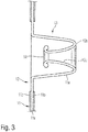
- the free end of the second, radially inner leg 13c delimits the opening 14 formed in the inner zone 12 of the sealing collar (see FIG Figure 3 ) through which the pipe 2 is passed.
- the web 13b is preferably designed to be curved, but can also be designed straight or as a pointed connection.
- Figure 1 and Figure 2 run the two legs 13a and 13c of the ring profile 13 approximately parallel to each other. This is not absolutely necessary, but can result if the ring profile is pushed into the space and slipped over the pipe 2.
- the opening 14 is widened when the tube 2 is inserted, the radially inner leg 13c is pressed against the radially outer leg 13a and both legs with the web are pressed radially outward.
- the outer diameter of the part of the ring profile seal 13 determined by the radially outer leg 13a can taper in the direction away from the first side of the flat, planar area of the inner zone 12 or the outer zone 13, so that the ring profile seal has a conical outer shape.
- the second embodiment shown is the outer zone 11 of the sealing collar 1 like the outer zone 11 of the sealing collar 1 from FIG Figure 1 and Figure 2 formed in three layers, the inner layer being formed by a film or sheet-like layer and the two displays of fleece-like layers.
- the materials of the outer zone are chosen so that it is flexible and sometimes also elastic. "Flexible” is the property of a material to bend under the influence of a force directed across the surface.
- the inner zone 12 comprising the ring profile 13 is formed from a film-shaped, elastic material, the axis of symmetry 15 of the ring profile being perpendicular to the Extends to the level of the outer zone.
- the inner layer 11a of the outer zone 11 is formed in one piece, ie integrally, with the inner zone 12 of the sealing collar.
- the flat, level area of the inner zone 12 is attached to the surface of the outer zone 11, for example by gluing or welding.
- Preferred configurations of the first embodiment had a three-layer outer zone formed from polypropylene, the inner layer being formed from a polypropylene film and the two outer layers each being formed from a polypropylene fleece.
- the inner zone including the ring profile, is made of a thermoplastic elastomer.
- the inner layer of the outer zone and inner zone which are made in one piece, consist of a thermoplastic elastomer, while the outer layers of the outer zone are each formed from a polypropylene fleece.
- the thickness of the ring profile can change along its profile course.
- the thickness of the radially inner leg 13c from the web to the opening 14 can be reduced, so that the leg 13c reliably nestles against the tube 2 over its entire surface in the region of the opening.
- the end of the profile adjoining the opening 14 of the sealing collar 1 can be slightly thickened radially outward, whereby a greater pressure is exerted on the outer circumference of the tube 2 in the area of the opening of the ring profile and the radially inner leg 13c nevertheless extends hugs the entire surface of the pipe.
- the diameter of the ring profile 13 at the transition from the radially inner leg 13c to the web 13b corresponds approximately to the outer diameter of the pipe to be sealed.
- the thickness of the ring profile is approximately constant along its profile course.
- the radially inner leg 13a is designed to be wavy, so that, instead of resting against the entire surface of the pipe 2, several of them are spaced apart in the direction of the axis of symmetry of the ring profile, similar to the sealing lips arranged one behind the other annular areas on the tube 2 applies. With this arrangement, a greater local contact pressure can be achieved, the security of the seal being ensured by the several "sealing rings" arranged one behind the other.
- the ring profile seal of the sealing collar is slipped over the pipe end and then pushed into the space between the pipe and the wall or floor with a suitable ring-shaped tool inserted into the inner area of the U-shaped ring profile so that the flat area of the seal (outer zone and level, flat area of the inner zone) lies flat against the wall.
- a suitable ring-shaped tool inserted into the inner area of the U-shaped ring profile so that the flat area of the seal (outer zone and level, flat area of the inner zone) lies flat against the wall.
- the ring profile can also be used with a rod, e.g. B. a wooden stick into the space.
Landscapes
- Engineering & Computer Science (AREA)
- General Engineering & Computer Science (AREA)
- Mechanical Engineering (AREA)
- Gasket Seals (AREA)
Description
- Die Erfindung betrifft die Abdichtung von Rohrdurchführungen in Verbindung mit Verbundabdichtungen.
- Gemäß der Normen DIN 18 531, DIN 18 532, DIN 18 533 und DIN 18 534 sind Bauwerke und Bauteile so zu planen und auszuführen, dass keine Schäden durch Wasser oder Feuchtigkeit entstehen. In der Folge ist die Bausubstanz durch geeignete Abdichtungsmaßnahmen zu schützen.
- Hierfür werden häufig keramische Verbundabdichtungssysteme verwendet. Diese setzen sich in der Regel aus einer keramischen Fliese oder Platte, Fugenmörtel zwischen den Fliesen oder Platten, unter der Fliese oder Platte befindlichen Fliesenkleber und einer Abdichtung zusammen. Die Abdichtung ist in der Regel zwischen dem Fliesenkleber und einer Wand oder einem Boden (beispielsweise aus Ziegel oder Beton) angeordnet und mit der Wand bzw. dem Boden verklebt. Für die Abdichtung werden flüssige oder bahnförmige Abdichtstoffe verwendet. Geeignete flüssige Abdichtstoffe können in unterschiedlichen Ausgestaltungen beispielsweise unter den Bezeichnungen FlächenDicht flexibel (FDF), DichtSchlämme Flex (DSF), TurboDichtSchlämme (TDS) oder PU-FlächenDicht (PU-FD) von der Sopro Bauchemie GmbH, Wiesbaden, Deutschland bezogen werden. Geeignete bahnförmige Abdichtstoffe können in unterschiedlichen Ausgestaltungen beispielsweise unter der Bezeichnung Abdichtungs- und EntkopplungsBahn AEB (Geschütztes Warenzeichen) von der Sopro Bauchemie GmbH, Wiesbaden, Deutschland bezogen werden. Derartige bahnförmige Abdichtstoffe bestehen beispielsweise aus reißfester Polypropylenfolie mit einer beidseitigen speziellen Vliesgewebebeschichtung aus Polypropylen und einer Dicke von ca. 0,3 mm bis 0,9 mm.
- Grundsätzlich sind bahnförmige Abdichtstoffe (im Folgenden: Abdichtungsbahn) üblicherweise dünnschichtige, wasserundurchlässige und rissüberbrückende, sowie zur Erhöhung der Haftung vlieskaschierte Kunststoffbahnen die auf die abzudichtenden Flächen ganzflächig aufgeklebt werden.
- Eine besondere Problematik stellen bei der Verwendung von Abdichtungsbahnen Rohrdurchführungen dar, da diese die flächige wasserdichte Bahn, die auch als Abdichtungsschicht bzw. Verbundabdichtung bezeichnet wird, durchbrechen und einen Wasserdurchtritt an der Grenze zwischen Rohr und Abdichtungsbahn ermöglichen. Zur Abdichtung von Rohrdurchführungen werden gegenwärtig blatt- bzw. folienförmige Dichtmanschetten mit einer flexiblen Innenzone (z. B. aus einem thermoplastischen Elastomer) verwendet. In der Innenzone ist ein Loch ausgebildet, das kleiner als der äußere Rohrdurchmesser ist, sodass sich die Innenzone, wenn die Dichtmanschette über das Rohrende gezogen wird, dichtend an die Außenwand des Rohres anlegt. Die Außenzone der Dichtmanschette wird flächig auf die darunter liegende Abdichtungsbahn geklebt. Das Material der Außenzone der Dichtmanschette entspricht in der Regel dem der verwendeten Abdichtungsbahn oder ist diesem bezüglich seiner bauphysikalischen Eigenschaften zumindest ähnlich.
- Um eine sichere Abdichtung gegenüber Wasser zu gewährleisten, muss die Dichtfläche zwischen der flexiblen Innenzone der Dichtmanschette und dem Rohr ausreichend groß sein, d. h. das Rohr weit genug aus der Wand bzw. aus dem Boden ragen. Da bei dem in Feucht- und Nassräumen üblichen mehrschichtigen Aufbau aus Untergrund, Abdichtung, Kleber und Belag für die Endmontage einer Armatur wie beispielsweise eines Wasserhahns nur sehr wenig Spielraum bezüglich des Rohrüberstands gegeben ist, ist dieser für eine sichere Abdichtung häufig zu gering. Zudem besteht die Gefahr, dass die Dichtmanschette bei der Endmontage als störend empfunden und beschädigt oder gar entfernt wird.
- Die
US 5,983,924 offenbart eine Wasserableitvorrichtung um Wasser, das aus einer hinter einer Wand angebrachten Sanitärarmatur austritt, zur Vorderseite der Wand abzuleiten, wobei die Vorrichtung eine Hülse, einen inneren Flansch und einen äußeren Flansch umfasst. Vorzugsweise hat der äußere Flansch eine Wandstärke von 0,6 mm und innere Flansch eine Wandstärke von 0,7 mm. - Es besteht daher ein Bedarf an einer Dichtmanschette zur Abdichtung von Rohrdurchführungen in Verbindung mit Verbundabdichtungen (beispielsweise im Wand- und Bodenbereich unter Fliesen, Platten und keramischen Belägen), die auch bei kurzen Rohrüberständen eine sichere Abdichtung gegenüber Wasser gewährleistet.
- Die vorstehende Aufgabe wird durch die Kombination der Merkmale des Anspruchs 1 gelöst. Bevorzugte Weiterbildungen finden sich in den Unteransprüchen.
- Eine solche Dichtmanschette weist eine elastische Innenzone mit einer darin ausgebildeten Ringprofildichtung auf, deren Symmetrieachse sich senkrecht zur Ebene der Außenzone erstreckt, sodass sich die Ringprofildichtung bei bestimmungsgemäßem Einsatz an das Rohr anschmiegend von der Wandoberfläche in die Wand hinein erstreckt.
- Die Dichtmanschette weist insbesondere eine flache, blatt- bzw. folienförmige Außenzone aus wasserdichtem Material auf, die die Innenzone aus wasserdichtem elastischem Material lateral wasserdicht umschließt. In der Innenzone ist eine von einem Ringprofil umschlossene Öffnung ausgebildet. Der radial äußere Umfang des Ringprofils schließt an einen flachen, ebenen Bereich der Innenzone, der mit der Außenzone dicht verbunden ist, oder direkt an die Außenzone an.
- Unter dem Begriff "elastisch" ist in dieser Schrift eine Werkstoffeigenschaft zu verstehen, die bewirkt, dass sich ein Werkstoff unter Krafteinwirkung verformt und bei Wegfall der Krafteinwirkung in seine ursprüngliche Form zurückkehrt. Unter dem Begriff "Öffnung" ist ein Loch zu verstehen, das einen Körper vollständig durchsetzt. Der Begriff "Ringprofil" bezeichnet einen nicht-flachen ringförmigen Körper, der wenigstens eine sich in Richtung der Symmetrieachse des Rings erstreckende Ausdehnung aufweist, welche sich von der Materialstärke des Körpers unterscheidet. Im einfachsten Fall ist die Querschnittsform des Ringprofils in Umfangsrichtung des Rings konstant. In anderen Fällen ändert sich die Querschnittsform des Profils entlang von dessen Umfangsrichtung. In jedem Fall, weist das Ringprofil keine Unterbrechungen in Umfangsrichtung auf.
- Bei einer Ausführungsform weist das Ringprofil einen U-förmigen Querschnitt mit zwei durch einen Steg verbundenen Schenkeln auf, wobei der Steg in einem Abstand zu einer ersten Seite des flachen, ebenen Bereichs der Innenzone bzw. der Außenzone angeordnet ist, der radial äußere Schenkel an den flachen, ebenen Bereich der Innenzone oder direkt an die Außenzone anschließt, der radial innere Schenkel die Begrenzung der Öffnung bildet und die Innenseite des U-förmigen Ringprofils an die der ersten Seite gegenüberliegende zweite Seite des flachen, ebenen Bereichs der Innenzone oder an die Außenzone anschließt.
- Bei Ausführungsformen liegt der Abstand des Steges zur ersten Seite des flachen ebenen Bereichs der Innenzone im Bereich von 5 mm bis 50 mm oder von 10 bis 30 mm.
- Bei Ausführungsformen liegt die Stegbreite bzw. der Abstand der Außenseiten der Schenkel am Steg im Bereich von 1 bis 15 mm.
- Bei Ausführungsformen weist das die Öffnung begrenzende Schenkelende eine radial auswärts gerichtete Krümmung auf.
- Bei Ausführungsformen ändert sich das Vorzeichen der Krümmung der Ringprofildichtung zwischen dem Bereich, an welchem die Innenzone an die Außenzone der Dichtmanschette angrenzt, und der in der Innenzone ausgebildeten Öffnung wenigstens einmal.
- Ausführungsformen weisen eine Dichtmanschette mit einer dreilagig ausgebildeten Außenzone und einer einlagig ausgebildeten elastischen Innenzone auf.
- Bei Ausführungsformen ist die Innenlage einer dreilagigen Außenzone der Dichtmanschette integral mit der elastischen Innenzone der Dichtmanschette ausgebildet, wobei die äußeren Ränder der beiden Außenlagen der Außenzone den äußeren Rand der Dichtmanschette bilden und die inneren Ränder der beiden Außenlagen die Innenzone der Dichtmanschette umschließen.
- Bei anderen Ausführungsformen ist die Innenzone der Dichtmanschette aus einem von der Dichtmanschette bzw. der Innenlage der Dichtmanschette verschiedenen Material gefertigt und an einer Seite der Dichtmanschette im Innenbereich der Außenzone angebracht. Bei alternativen Ausführungsformen sind die Außenbereiche der Innenzone zwischen den äußeren Lagen im Innenbereich der Außenzone eingefasst. Die Verbindung von Innenzone und Außenzone kann mittels Kleben oder Schweißen erfolgen.
- Ausführungsformen einer wie zuvor angegebenen Dichtmanschette weisen eine aus einem thermoplastischen Elastomer gebildete Innenzone und eine aus Polypropylen gebildete Außenzone auf. Dreilagige Außenzonen sind bei Ausführungsformen aus einer zwischen zwei Vliesen eingefassten Folie aufgebaut. Bei einer integral ausgebildeten Dichtmanschette ist das die Innenzone und die Innenlage der Außenzone bildende Element der Dichtmanschette aus einem thermoplastischen Elastomer gebildet, während die beiden Außenlagen der Außenzone der Dichtmanschette aus einem Polypropylenvlies gebildet sind.
- Die Dicke des Materials in der elastischen Innenzone liegt bei Ausführungsformen im Bereich von 200 bis 400 µm, die der Außenzone im Bereich von 300 bis 500 µm.
- Ausführungsformen einer Verwendung einer wie vorstehend beschriebenen Dichtmanschette zur Abdichtung eines durch eine Wand oder einen Boden geführten Rohres zeichnen sich dadurch aus, dass die Dichtmanschette so an der Wand oder dem Boden angeordnet und insbesondere so mit der Wand verklebt wird, dass sich das Rohr durch die in der Innenzone ausgebildete Öffnung hindurch erstreckt, und dass sich die größte Ausdehnung der Ringprofildichtung in Richtung der Symmetrieachse in die Wand oder den Boden hinein erstreckt.
- Weitere Merkmale einer wie oben spezifizierten Dichtmanschette mit einer elastischen Innenzone, die eine darin ausgebildete Ringprofildichtung aufweist, ergeben sich aus der nachfolgenden Beschreibung von Ausführungsbeispielen in Verbindung mit den Ansprüchen und den Figuren. Die nachfolgende Erläuterung einiger Ausführungsbeispiele der Erfindung nimmt auf die beiliegenden Figuren Bezug, von denen
- Figur 1
- eine mit einer Dichtmanschette gemäß einer Ausführungsform abgedichtete Rohrdurchführung in einer Wand in einer perspektivischen Schnittdarstellung zeigt,
- Figur 2
- die mit einer Dichtmanschette gemäß
Figur 1 abgedichtete Rohrdurchführung in einer Querschnittsansicht zeigt, und - Figur 3
- ein Beispiel für eine Ausgestaltung eines Ringprofils für eine Dichtmanschette gemäß einer anderen Ausführungsform zeigt und
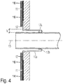
- Figur 4
- die mit einer Dichtmanschette gemäß
Figur 1 abgedichtete Rohrdurchführung in einer Querschnittsansicht zeigt, wobei zusätzlich Fliesen dargestellt sind, welche die Dichtmanschette abschnittsweise bedecken. - Es sei darauf hingewiesen, dass die Erfindung nicht auf die Ausführungsformen der beschriebenen Ausführungsbeispiele beschränkt, sondern durch den Umfang der beiliegenden Patentansprüche bestimmt ist. Insbesondere können die einzelnen Merkmale bei erfindungsgemäßen Ausführungsformen in anderer Anzahl und Kombination als bei den untenstehend angeführten Beispielen verwirklicht sein. In den Figuren werden gleiche Bezugszeichen für funktionell gleichwertige oder ähnliche Charakteristiken unabhängig von speziellen Ausführungsformen verwendet.
- Die Darstellung von
Figur 1 zeigt eine perspektivische Schnittdarstellung eines durch eine Wand geführten Rohrs, wobei die Rohrdurchführung mit einer Dichtmanschette gemäß einer Ausführungsform abgedichtet ist. Die Darstellung vonFigur 2 zeigt die mit einer Dichtmanschette gemäßFigur 1 abgedichtete Rohrdurchführung in einer Querschnittsansicht. - In dem dargestellten Beispiel handelt es sich bei der Wand 3 um eine Trockenbauwand mit einer Öffnung 4, durch die sich ein Rohr 2 hindurch erstreckt. Das Rohr 2 weist an der Vorderseite 3a der Wand 3 einen Überstand auf, dessen Länge sich durch den auf die Vorderseite der Wand aufzubringenden Belag bestimmt. Bei dem Belag handelt es sich üblicherweise um Fliesen, Platten oder keramische Beläge. Diese Fliesen 16 sind nur in
Figur 4 gezeigt und in denFiguren 1 und 2 nicht dargestellt. InFigur 4 wurde der besseren Übersicht wegen auf die Darstellung eines Klebers zwischen Wand 3 und Dichtmanschette sowie zwischen Dichtmanschette und Fliese 16 verzichtet. In der Regel wird die Vorderseite 3a von einer auf die entsprechende Wandoberfläche aufgebrachten Abdichtungs- und Entkopplungsbahn gebildet. Anders als aus der Figur ersichtlich wird das Rohr hinter der Rückseite 3b der Wand fortgeführt. Statt einer Trockenbauwand kann das Rohr auch aus einer massiven Wand herausgeführt werden. Hierbei kann das Rohr sowohl innerhalb der Wand als auch durch die Wand geführt sein. - An der Vorderseite der Wand befindet sich eine Dichtmanschette 1, deren Außenzone 11 auf die Vorderseite der Wand 3 aufgebracht ist. Die Außenzone 11 umschließt lateral eine Innenzone 12, in der ein Ringprofil 13 ausgebildet ist. Das Ringprofil 13 erstreckt sich von der Vorderseite der Wand 3 durch den zwischen dem Rohr 2 und der Wand ausgebildeten Zwischenraum in Richtung zur Rückseite der Wand 3 und im dargestellten Fall in den Raum hinter der Rückseite der Wand.
- Die Breite b des zum Einsetzen des Ringprofils erforderlichen ringförmigen Zwischenraums beträgt bei Ausführungsformen zwischen etwa 5 und 15 mm. Die Breite des Zwischenraums kann vom Durchmesser des gegenüber der Wand abzudichtenden Rohres abhängig gewählt sein. Bei massiven Wänden kann der Zwischenraum durch Ausbilden einer um das Rohr herum geführten Vertiefung in der Wand gebildet werden, wobei die Vertiefung je nach Ausführungsform der Dichtmanschette 1 etwa 10 bis etwa 30 mm in die Wand hineinreicht. Die Abmessung des Ringprofils senkrecht zur Ebene der Außenzone 11 ist vorzugsweise kleiner als die Tiefe der Vertiefung, sodass das Ringprofil im Einsatz den Boden der Ausnehmung nicht berührt. Hierdurch wird sichergestellt, dass die Dichtmanschette 1 auch im Bereich des Rohrs 2 eben an der Vorderseite 3a der Wand 3 anliegt.
- Bei der in den
Figuren 1 und 2 dargestellten ersten Ausführungsform der Dichtmanschette 1 ist das Ringprofil U-förmig ausgebildet, d. h., dass der Querschnitt des Ringprofils U-förmig ist. Das U-förmige Profil weist einen ersten Schenkel 13a, einen zweiten Schenkel 13c und einen den ersten Schenkel 13a mit dem zweiten Schenkel 13c verbindenden Steg 13b auf. Der erste Schenkel 13a ist radial außerhalb des Steges 13b, der zweite Schenkel 13c ist radial innerhalb des Steges 13b angeordnet. Der erste, radial äußere Schenkel 13a verbindet den Steg 13b mit dem flachen, ebenen Bereich der Innenzone oder direkt mit der Außenzone. Das freie Ende des zweiten, radial inneren Schenkels 13c begrenzt die in der Innenzone 12 der Dichtmanschettel ausgebildete Öffnung 14 (sieheFigur 3 ), durch die das Rohr 2 geführt ist. Der Steg 13b ist vorzugsweise gekrümmt ausgebildet, kann aber auch gerade oder als spitze Verbindung ausgebildet sein. In den Darstellungen vonFigur 1 und Figur 2 verlaufen die beiden Schenkel 13a und 13c des Ringprofils 13 in etwa parallel zueinander. Dies ist nicht unbedingt erforderlich, kann sich aber ergeben, wenn das Ringprofil in den Zwischenraum geschoben und über das Rohr 2 gestülpt wird. - Bei Ausführungsformen sind die beiden Schenkel - wie in der Querschnittsdarstellung von
Figur 3 veranschaulicht - so unter einem Winkel zueinander angeordnet, dass ihr Abstand zueinander mit zunehmender Entfernung vom Steg 13b zunimmt. Durch diese Formgebung wird die Öffnung 14 beim Einführen des Rohres 2 aufgeweitet, der radial innere Schenkel 13c gegen den radial äußeren Schenkel 13a und beide Schenkel mit dem Steg radial nach außen gedrückt. Ferner kann sich zudem der Außendurchmesser des durch den radial äußeren Schenkel 13a bestimmten Teils der Ringprofildichtung 13 in Richtung weg von der ersten Seite des flachen, ebenen Bereichs der Innenzone 12 bzw. der Außenzone 13 verjüngen, sodass die Ringprofildichtung eine konische Außenform aufweist. - Bei der in
Figur 3 dargestellten zweiten Ausführungsform ist die Außenzone 11 der Dichtmanschette 1 wie die Außenzone 11 der Dichtmanschette 1 vonFigur 1 und Figur 2 dreilagig ausgebildet, wobei die Innenlage von einer folien- oder blattförmigen Schicht und die beiden Auslagen von vliesartigen Schichten gebildet sind. Die Materialien der Außenzone sind so gewählt, dass diese flexibel, mitunter auch elastisch ist. Unter "flexibel" ist die Eigenschaft eines Materials zu verstehen, sich unter dem Einfluss einer quer zur Oberfläche gerichteten Kraft zu verbiegen. Die das Ringprofil 13 umfassende Innenzone 12 ist aus einem folienförmigen, elastischen Material gebildet, wobei sich die Symmetrieachse 15 des Ringprofils senkrecht zur Ebene der Außenzone erstreckt. Anders als bei der in denFiguren 1 und 2 dargestellten Ausführungsform ist die Innenlage 11a der Außenzone 11 einstückig, d. h. integral, mit der Innenzone 12 der Dichtmanschette ausgebildet. Bei der Ausführungsform vonFigur 1 und Figur 2 ist der flache, ebene Bereich der Innenzone 12 an der Oberfläche der Außenzone 11 angebracht, beispielsweise durch Kleben oder Schweißen. - Bevorzugte Ausgestaltungen der ersten Ausführungsform wiesen eine aus Polypropylen gebildete dreilagige Außenzone auf, wobei die Innenlage von einer Polypropylenfolie und die beiden Außenlagen jeweils aus einem Polypropylenvlies gebildet sind. Die Innenzone ist einschließlich des Ringprofils aus einem thermoplastischen Elastomer gebildet.
- Bei bevorzugten Ausgestaltungen der zweiten Ausführungsform bestehen Innenlage der Außenzone und Innenzone, die einstückig ausgeführt sind, aus einem thermoplastischen Elastomer, während die Außenlagen der Außenzone jeweils aus einem Polypropylenvlies gebildet sind.
- Bei einer Herstellung der Innenzone 12 in Spritzgusstechnik kann sich die Dicke des Ringprofils entlang seines Profilverlaufs ändern. Insbesondere kann die Dicke des radial inneren Schenkels 13c vom Steg zur Öffnung 14 geringer werden, sodass sich der Schenkel 13c im Bereich der Öffnung zuverlässig ganzflächig an das Rohr 2 anschmiegt. Bei anderen Ausführungsformen kann das an die Öffnung 14 der Dichtmanschette 1 anschließende Ende des Profils etwas radial nach außen verdickt sein, wodurch im Bereich der Öffnung des Ringprofils ein stärkerer Druck auf den äußeren Umfang des Rohrs 2 bewirkt wird und der radial innere Schenkel 13c sich dennoch ganzflächig an das Rohr anschmiegt. Zur einfachen Montage entspricht der Durchmesser des Ringprofils 13 am Übergang vom radial inneren Schenkel 13c zum Steg 13b in etwa dem Außendurchmesser des abzudichtenden Rohrs. Bei anderen Ausführungsformen ist die Dicke des Ringprofils entlang seines Profilverlaufs in etwa konstant.
- Bei anderen Ausführungsformen bzw. Ausgestaltungen der in den Figuren dargestellten Ausführungsformen ist der radial innere Schenkel 13a wellig ausgeführt, sodass er sich, statt sich ganzflächig an das Rohr 2 anzulegen, ähnlich wie bei hintereinander angeordneten Dichtlippen in mehreren in Richtung der Symmetrieachse des Ringprofils zueinander beabstandeten ringförmigen Bereichen an das Rohr 2 anlegt. Mit dieser Anordnung kann eine größere lokale Anpresskraft erzielt werden, wobei die Sicherheit der Abdichtung durch die mehreren hintereinander angeordneten "Dichtringe" gewährleistet ist.
- Zur Montage wird die Ringprofildichtung der Dichtmanschette über das Rohrende gestülpt und dann mit einem passenden, in den Innenbereich des U-förmigen Ringprofils eingeführten ringförmigen Werkzeug soweit in den Zwischenraum zwischen Rohr und Wand bzw. Boden eingeschoben, dass der flache Bereich der Dichtung (Außenzone und ebener, flacher Bereich der Innenzone) plan an der Wand anliegt. Statt mit einem ringförmigen Werkzeug kann das Ringprofil auch mit einem Stäbchen, z. B. einem Holzstäbchen in den Zwischenraum eingebracht werden.
Claims (13)
- Dichtmanschette zur Abdichtung eines durch eine Wand (3) oder einen Boden geführten Rohrs (2) gegenüber der Wand bzw. dem Boden, wobei die Dichtmanschette (1) aufweist:eine flache, blattförmige oder folienförmige wasserdichte Außenzone (11), undeine Innenzone (12) aus einem wasserdichten elastischen Material, die von der Außenzone (11) lateral wasserdicht umschlossen ist und in der eine Ringprofildichtung (13) ausgebildet ist, deren Symmetrieachse (15) sich senkrecht zur Ebene der Außenzone (11) erstreckt und die eine Öffnung (14) umgrenzt, die kleiner als der Außendurchmesser des abzudichtenden Rohrs (2) ist, wobei die Ringprofildichtung (13) wenigstens eine sich in Richtung der Symmetrieachse (15) erstreckende Ausdehnung aufweist, welche sich von der Materialstärke der Innenzone (12) unterscheidet,wobei die Dicke des Materials in der elastischen Innenzone im Bereich von 200 bis 400 µm und die Dicke der Außenzone im Bereich von 300 bis 500 µm liegt,wobei das Ringprofil einen U-förmigen Querschnitt mit zwei durch einen Steg (13b) verbundenen Schenkeln (13a, 13c) aufweist, wobei der Steg (13b) in einem Abstand zu einer ersten Seite eines flachen, ebenen Bereichs der Innenzone (12) bzw. der Außenzone (11) angeordnet ist, der radial äußere Schenkel (13a) an den flachen, ebenen Bereich der Innenzone (12) oder direkt an die Außenzone (11) anschließt, der radial innere Schenkel (13c) die Begrenzung der Öffnung (14) bildet und die Innenseite des U-förmigen Ringprofils der Ringprofildichtung (13) an die der ersten Seite gegenüberliegende zweite Seite des flachen, ebenen Bereichs der Innenzone oder direkt an die Außenzone anschließt, und wobei die erste Seite die zum Kontakt mit Wand (3) vorgesehene Seite der Dichtmanschette (1) ist.
- Dichtmanschette nach Anspruch 1, wobei der radial äußere Umfang der Ringprofildichtung (13) an einen flachen, ebenen Bereich der Innenzone (12), der mit der Außenzone (11) wasserdicht verbunden ist, oder direkt an die Außenzone (11) anschließt.
- Dichtmanschette nach Anspruch 1 oder 2, wobei der Abstand des Steges (13b) zur ersten Seite des flachen ebenen Bereichs der Innenzone (12) bzw. der Außenzone (11) im Bereich von 5 mm bis 50 mm oder von 10 mm bis 30 mm liegt.
- Dichtmanschette nach Anspruch 1, 2 oder 3, wobei der Abstand der Außenseiten der Schenkel am Steg im Bereich von 1 mm bis 15 mm liegt.
- Dichtmanschette nach einem der Ansprüche 1 bis 4, wobei der Abstand der beiden Schenkel (13a, 13c) zueinander in Richtung zur ersten Seite des flachen, ebenen Bereichs der Innenzone (12) bzw. der Außenzone (13) mit zunehmender Entfernung vom Steg (13b) zunimmt.
- Dichtmanschette nach einem der Ansprüche 1 bis 5, wobei sich der Außendurchmesser des durch den radial äußeren Schenkel (13a) bestimmten Teils der Ringprofildichtung (13) in Richtung weg von der ersten Seite des flachen, ebenen Bereichs der Innenzone (12) bzw. der Außenzone (13) verjüngt.
- Dichtmanschette nach einem der Ansprüche 1 bis 6, wobei das die Öffnung (14) begrenzende Schenkelende eine radial auswärts gerichtete Krümmung aufweist.
- Dichtmanschette nach Anspruch 7, wobei das das die Öffnung (14) begrenzende Schenkelende verdickt ausgebildet ist.
- Dichtmanschette nach einem der Ansprüche 1 bis 8, wobei die Dichtmanschette (1) eine dreilagig ausgebildete Außenzone (11) und einlagig ausgebildete elastische Innenzone (12) aufweist.
- Dichtmanschette nach Anspruch 9, wobei die Innenlage der Außenzone (11) einstückig mit der Innenzone (12) ausgebildet ist.
- Dichtmanschette nach Anspruch 9, wobei die Außenzone (11) eine Polypropylenfolie umfasst, die zwischen zwei Polypropylenvliesen eingefasst ist.
- Dichtmanschette nach Anspruch 10, wobei die Innenlage der Außenzone (11) der Dichtmanschette (1) zwischen zwei Polypropylenvliesen eingefasst ist.
- Dichtmanschette nach einem der vorhergehenden Ansprüche, wobei das elastische Material der Innenzone (12) ein thermoplastisches Elastomer ist.
Applications Claiming Priority (3)
| Application Number | Priority Date | Filing Date | Title |
|---|---|---|---|
| DE102018110768.4A DE102018110768A1 (de) | 2018-05-04 | 2018-05-04 | Dichtmanschette für Verbundabdichtungen |
| DE202018102495.7U DE202018102495U1 (de) | 2018-05-04 | 2018-05-04 | Dichtmanschette für Verbundabdichtungen |
| PCT/EP2019/061444 WO2019211467A1 (de) | 2018-05-04 | 2019-05-03 | Dichtmanschette für verbundabdichtungen |
Publications (2)
| Publication Number | Publication Date |
|---|---|
| EP3735548A1 EP3735548A1 (de) | 2020-11-11 |
| EP3735548B1 true EP3735548B1 (de) | 2021-08-04 |
Family
ID=66448542
Family Applications (1)
| Application Number | Title | Priority Date | Filing Date |
|---|---|---|---|
| EP19722850.5A Active EP3735548B1 (de) | 2018-05-04 | 2019-05-03 | Dichtmanschette für verbundabdichtungen |
Country Status (2)
| Country | Link |
|---|---|
| EP (1) | EP3735548B1 (de) |
| WO (1) | WO2019211467A1 (de) |
Families Citing this family (1)
| Publication number | Priority date | Publication date | Assignee | Title |
|---|---|---|---|---|
| WO2022140815A1 (de) * | 2020-12-30 | 2022-07-07 | Schoerflinger Alexander | Wand und rohrdurchführung für ein rohr an dieser wand |
Family Cites Families (4)
| Publication number | Priority date | Publication date | Assignee | Title |
|---|---|---|---|---|
| CH681651A5 (de) * | 1990-10-05 | 1993-04-30 | Huber+Suhner Ag | |
| AUPN023694A0 (en) * | 1994-12-22 | 1995-01-27 | H.P.H. Pty. Ltd. | A fluid apron |
| AU699999B2 (en) * | 1995-03-31 | 1998-12-17 | Robert Kenneth Moule | Penetration sealing member |
| DE19800115A1 (de) * | 1998-01-05 | 1999-07-22 | Norega Ag | Manschette, insbesondere zur Leitungs- und Leitungsumgebungsisolation bei Gebäudeinstallationen im Wohn, Wirtschafts- und Industriebau |
-
2019
- 2019-05-03 EP EP19722850.5A patent/EP3735548B1/de active Active
- 2019-05-03 WO PCT/EP2019/061444 patent/WO2019211467A1/de not_active Ceased
Also Published As
| Publication number | Publication date |
|---|---|
| EP3735548A1 (de) | 2020-11-11 |
| WO2019211467A1 (de) | 2019-11-07 |
Similar Documents
| Publication | Publication Date | Title |
|---|---|---|
| EP0393304B1 (de) | Verfahren zum Auskleiden eines im Erdreich verlegten Leitungsrohres | |
| AT15972U1 (de) | Installationsblock | |
| EP3735548A1 (de) | Dichtmanschette für verbundabdichtungen | |
| DE102006035135B4 (de) | Noppenbauelement | |
| EP3358235B1 (de) | Dichtelement zum abdichten einer gebäudestruktur | |
| DE102020103084A1 (de) | Dichtelement für eine Gebäudestruktur, Verfahren zur Herstellung eines Dichtelements und Gebäudestruktur mit Dichtelement | |
| CH711482A2 (de) | Schnittschutzstreifen und Verwendung eines Schnittschutzstreifens. | |
| DE102018110768A1 (de) | Dichtmanschette für Verbundabdichtungen | |
| DE202018102495U1 (de) | Dichtmanschette für Verbundabdichtungen | |
| DE19745599C2 (de) | Verbundrohr und Verfahren zu dessen Herstellung | |
| AT519806B1 (de) | Vorrichtung zum Erstellen eines Übergangs zwischen einer Sanitäreinrichtung und einer Vertikalfläche sowie ein Verfahren zum Erstellen eines solchen Übergangs und ein Feucht- oder Nassbereich mit einem solchen Übergang | |
| DE8121570U1 (de) | Dichtungsmanschette fuer rohrdurchfuehrungen | |
| DE29710474U1 (de) | Randstreifen aus Kunststoffschaumstoff | |
| EP3357682B2 (de) | Gebäudestruktur | |
| WO2006111288A1 (de) | Bauabdichtmaterial | |
| EP3900588B1 (de) | Sanitär-dichtungsband zum abdichten eines anschlussbereiches | |
| EP4357551B1 (de) | Putzprofil | |
| DE102018119205A1 (de) | Vorrichtung zum Durchführen einer Leitung durch eine Bodenplatte und Bodenplatte für ein Gebäude | |
| DE29911070U1 (de) | Dichtungsmanschette und Rohling für eine Dichtungsmanschette | |
| DE102004054099A1 (de) | Trittschalldämmung | |
| DE10252539B3 (de) | Noppenbahn zum Abdichten von Bauwerken | |
| DE2649957C2 (de) | Betonbauwerk mit einer Kunststoffschutzbahn | |
| DE202014105289U1 (de) | Gittergewebe für die Bewehrung von winkligen Treppenabschnitten einer Treppe | |
| CH712745A2 (de) | Schnittschutz zur Verwendung im Feucht- oder Nassbereich eines Gebäudes und Gebäudebereich mit einem solchen Schnittschutz. | |
| CH711947A2 (de) | Schnittschutzstreifen und Verfahren zum Anbringen eines Schnittschutzstreifens. |
Legal Events
| Date | Code | Title | Description |
|---|---|---|---|
| STAA | Information on the status of an ep patent application or granted ep patent |
Free format text: STATUS: UNKNOWN |
|
| STAA | Information on the status of an ep patent application or granted ep patent |
Free format text: STATUS: THE INTERNATIONAL PUBLICATION HAS BEEN MADE |
|
| PUAI | Public reference made under article 153(3) epc to a published international application that has entered the european phase |
Free format text: ORIGINAL CODE: 0009012 |
|
| STAA | Information on the status of an ep patent application or granted ep patent |
Free format text: STATUS: REQUEST FOR EXAMINATION WAS MADE |
|
| 17P | Request for examination filed |
Effective date: 20200806 |
|
| AK | Designated contracting states |
Kind code of ref document: A1 Designated state(s): AL AT BE BG CH CY CZ DE DK EE ES FI FR GB GR HR HU IE IS IT LI LT LU LV MC MK MT NL NO PL PT RO RS SE SI SK SM TR |
|
| AX | Request for extension of the european patent |
Extension state: BA ME |
|
| GRAP | Despatch of communication of intention to grant a patent |
Free format text: ORIGINAL CODE: EPIDOSNIGR1 |
|
| STAA | Information on the status of an ep patent application or granted ep patent |
Free format text: STATUS: GRANT OF PATENT IS INTENDED |
|
| DAV | Request for validation of the european patent (deleted) | ||
| INTG | Intention to grant announced |
Effective date: 20210226 |
|
| GRAS | Grant fee paid |
Free format text: ORIGINAL CODE: EPIDOSNIGR3 |
|
| GRAA | (expected) grant |
Free format text: ORIGINAL CODE: 0009210 |
|
| STAA | Information on the status of an ep patent application or granted ep patent |
Free format text: STATUS: THE PATENT HAS BEEN GRANTED |
|
| AK | Designated contracting states |
Kind code of ref document: B1 Designated state(s): AL AT BE BG CH CY CZ DE DK EE ES FI FR GB GR HR HU IE IS IT LI LT LU LV MC MK MT NL NO PL PT RO RS SE SI SK SM TR |
|
| REG | Reference to a national code |
Ref country code: GB Ref legal event code: FG4D Free format text: NOT ENGLISH |
|
| REG | Reference to a national code |
Ref country code: AT Ref legal event code: REF Ref document number: 1417310 Country of ref document: AT Kind code of ref document: T Effective date: 20210815 |
|
| REG | Reference to a national code |
Ref country code: CH Ref legal event code: EP |
|
| REG | Reference to a national code |
Ref country code: DE Ref legal event code: R096 Ref document number: 502019001972 Country of ref document: DE |
|
| REG | Reference to a national code |
Ref country code: IE Ref legal event code: FG4D Free format text: LANGUAGE OF EP DOCUMENT: GERMAN |
|
| REG | Reference to a national code |
Ref country code: LT Ref legal event code: MG9D |
|
| REG | Reference to a national code |
Ref country code: NL Ref legal event code: MP Effective date: 20210804 |
|
| PG25 | Lapsed in a contracting state [announced via postgrant information from national office to epo] |
Ref country code: SE Free format text: LAPSE BECAUSE OF FAILURE TO SUBMIT A TRANSLATION OF THE DESCRIPTION OR TO PAY THE FEE WITHIN THE PRESCRIBED TIME-LIMIT Effective date: 20210804 Ref country code: RS Free format text: LAPSE BECAUSE OF FAILURE TO SUBMIT A TRANSLATION OF THE DESCRIPTION OR TO PAY THE FEE WITHIN THE PRESCRIBED TIME-LIMIT Effective date: 20210804 Ref country code: ES Free format text: LAPSE BECAUSE OF FAILURE TO SUBMIT A TRANSLATION OF THE DESCRIPTION OR TO PAY THE FEE WITHIN THE PRESCRIBED TIME-LIMIT Effective date: 20210804 Ref country code: NO Free format text: LAPSE BECAUSE OF FAILURE TO SUBMIT A TRANSLATION OF THE DESCRIPTION OR TO PAY THE FEE WITHIN THE PRESCRIBED TIME-LIMIT Effective date: 20211104 Ref country code: PT Free format text: LAPSE BECAUSE OF FAILURE TO SUBMIT A TRANSLATION OF THE DESCRIPTION OR TO PAY THE FEE WITHIN THE PRESCRIBED TIME-LIMIT Effective date: 20211206 Ref country code: FI Free format text: LAPSE BECAUSE OF FAILURE TO SUBMIT A TRANSLATION OF THE DESCRIPTION OR TO PAY THE FEE WITHIN THE PRESCRIBED TIME-LIMIT Effective date: 20210804 Ref country code: HR Free format text: LAPSE BECAUSE OF FAILURE TO SUBMIT A TRANSLATION OF THE DESCRIPTION OR TO PAY THE FEE WITHIN THE PRESCRIBED TIME-LIMIT Effective date: 20210804 Ref country code: BG Free format text: LAPSE BECAUSE OF FAILURE TO SUBMIT A TRANSLATION OF THE DESCRIPTION OR TO PAY THE FEE WITHIN THE PRESCRIBED TIME-LIMIT Effective date: 20211104 Ref country code: LT Free format text: LAPSE BECAUSE OF FAILURE TO SUBMIT A TRANSLATION OF THE DESCRIPTION OR TO PAY THE FEE WITHIN THE PRESCRIBED TIME-LIMIT Effective date: 20210804 |
|
| PG25 | Lapsed in a contracting state [announced via postgrant information from national office to epo] |
Ref country code: PL Free format text: LAPSE BECAUSE OF FAILURE TO SUBMIT A TRANSLATION OF THE DESCRIPTION OR TO PAY THE FEE WITHIN THE PRESCRIBED TIME-LIMIT Effective date: 20210804 Ref country code: LV Free format text: LAPSE BECAUSE OF FAILURE TO SUBMIT A TRANSLATION OF THE DESCRIPTION OR TO PAY THE FEE WITHIN THE PRESCRIBED TIME-LIMIT Effective date: 20210804 Ref country code: GR Free format text: LAPSE BECAUSE OF FAILURE TO SUBMIT A TRANSLATION OF THE DESCRIPTION OR TO PAY THE FEE WITHIN THE PRESCRIBED TIME-LIMIT Effective date: 20211105 |
|
| PG25 | Lapsed in a contracting state [announced via postgrant information from national office to epo] |
Ref country code: NL Free format text: LAPSE BECAUSE OF FAILURE TO SUBMIT A TRANSLATION OF THE DESCRIPTION OR TO PAY THE FEE WITHIN THE PRESCRIBED TIME-LIMIT Effective date: 20210804 |
|
| PG25 | Lapsed in a contracting state [announced via postgrant information from national office to epo] |
Ref country code: DK Free format text: LAPSE BECAUSE OF FAILURE TO SUBMIT A TRANSLATION OF THE DESCRIPTION OR TO PAY THE FEE WITHIN THE PRESCRIBED TIME-LIMIT Effective date: 20210804 |
|
| REG | Reference to a national code |
Ref country code: DE Ref legal event code: R097 Ref document number: 502019001972 Country of ref document: DE |
|
| PG25 | Lapsed in a contracting state [announced via postgrant information from national office to epo] |
Ref country code: SM Free format text: LAPSE BECAUSE OF FAILURE TO SUBMIT A TRANSLATION OF THE DESCRIPTION OR TO PAY THE FEE WITHIN THE PRESCRIBED TIME-LIMIT Effective date: 20210804 Ref country code: SK Free format text: LAPSE BECAUSE OF FAILURE TO SUBMIT A TRANSLATION OF THE DESCRIPTION OR TO PAY THE FEE WITHIN THE PRESCRIBED TIME-LIMIT Effective date: 20210804 Ref country code: RO Free format text: LAPSE BECAUSE OF FAILURE TO SUBMIT A TRANSLATION OF THE DESCRIPTION OR TO PAY THE FEE WITHIN THE PRESCRIBED TIME-LIMIT Effective date: 20210804 Ref country code: EE Free format text: LAPSE BECAUSE OF FAILURE TO SUBMIT A TRANSLATION OF THE DESCRIPTION OR TO PAY THE FEE WITHIN THE PRESCRIBED TIME-LIMIT Effective date: 20210804 Ref country code: CZ Free format text: LAPSE BECAUSE OF FAILURE TO SUBMIT A TRANSLATION OF THE DESCRIPTION OR TO PAY THE FEE WITHIN THE PRESCRIBED TIME-LIMIT Effective date: 20210804 Ref country code: AL Free format text: LAPSE BECAUSE OF FAILURE TO SUBMIT A TRANSLATION OF THE DESCRIPTION OR TO PAY THE FEE WITHIN THE PRESCRIBED TIME-LIMIT Effective date: 20210804 |
|
| PLBE | No opposition filed within time limit |
Free format text: ORIGINAL CODE: 0009261 |
|
| STAA | Information on the status of an ep patent application or granted ep patent |
Free format text: STATUS: NO OPPOSITION FILED WITHIN TIME LIMIT |
|
| 26N | No opposition filed |
Effective date: 20220506 |
|
| REG | Reference to a national code |
Ref country code: BE Ref legal event code: MM Effective date: 20220531 |
|
| PG25 | Lapsed in a contracting state [announced via postgrant information from national office to epo] |
Ref country code: MC Free format text: LAPSE BECAUSE OF FAILURE TO SUBMIT A TRANSLATION OF THE DESCRIPTION OR TO PAY THE FEE WITHIN THE PRESCRIBED TIME-LIMIT Effective date: 20210804 Ref country code: LU Free format text: LAPSE BECAUSE OF NON-PAYMENT OF DUE FEES Effective date: 20220503 |
|
| PG25 | Lapsed in a contracting state [announced via postgrant information from national office to epo] |
Ref country code: IE Free format text: LAPSE BECAUSE OF NON-PAYMENT OF DUE FEES Effective date: 20220503 |
|
| PG25 | Lapsed in a contracting state [announced via postgrant information from national office to epo] |
Ref country code: BE Free format text: LAPSE BECAUSE OF NON-PAYMENT OF DUE FEES Effective date: 20220531 |
|
| P01 | Opt-out of the competence of the unified patent court (upc) registered |
Effective date: 20230519 |
|
| GBPC | Gb: european patent ceased through non-payment of renewal fee |
Effective date: 20230503 |
|
| PG25 | Lapsed in a contracting state [announced via postgrant information from national office to epo] |
Ref country code: MK Free format text: LAPSE BECAUSE OF FAILURE TO SUBMIT A TRANSLATION OF THE DESCRIPTION OR TO PAY THE FEE WITHIN THE PRESCRIBED TIME-LIMIT Effective date: 20210804 Ref country code: CY Free format text: LAPSE BECAUSE OF FAILURE TO SUBMIT A TRANSLATION OF THE DESCRIPTION OR TO PAY THE FEE WITHIN THE PRESCRIBED TIME-LIMIT Effective date: 20210804 Ref country code: GB Free format text: LAPSE BECAUSE OF NON-PAYMENT OF DUE FEES Effective date: 20230503 |
|
| PG25 | Lapsed in a contracting state [announced via postgrant information from national office to epo] |
Ref country code: HU Free format text: LAPSE BECAUSE OF FAILURE TO SUBMIT A TRANSLATION OF THE DESCRIPTION OR TO PAY THE FEE WITHIN THE PRESCRIBED TIME-LIMIT; INVALID AB INITIO Effective date: 20190503 |
|
| PG25 | Lapsed in a contracting state [announced via postgrant information from national office to epo] |
Ref country code: MT Free format text: LAPSE BECAUSE OF FAILURE TO SUBMIT A TRANSLATION OF THE DESCRIPTION OR TO PAY THE FEE WITHIN THE PRESCRIBED TIME-LIMIT Effective date: 20210804 |
|
| PGFP | Annual fee paid to national office [announced via postgrant information from national office to epo] |
Ref country code: DE Payment date: 20250522 Year of fee payment: 7 |
|
| PGFP | Annual fee paid to national office [announced via postgrant information from national office to epo] |
Ref country code: IT Payment date: 20250526 Year of fee payment: 7 |
|
| PGFP | Annual fee paid to national office [announced via postgrant information from national office to epo] |
Ref country code: CH Payment date: 20250601 Year of fee payment: 7 |
|
| PGFP | Annual fee paid to national office [announced via postgrant information from national office to epo] |
Ref country code: AT Payment date: 20250508 Year of fee payment: 7 |
|
| PG25 | Lapsed in a contracting state [announced via postgrant information from national office to epo] |
Ref country code: TR Free format text: LAPSE BECAUSE OF FAILURE TO SUBMIT A TRANSLATION OF THE DESCRIPTION OR TO PAY THE FEE WITHIN THE PRESCRIBED TIME-LIMIT Effective date: 20210804 |
|
| PG25 | Lapsed in a contracting state [announced via postgrant information from national office to epo] |
Ref country code: SI Free format text: LAPSE BECAUSE OF FAILURE TO SUBMIT A TRANSLATION OF THE DESCRIPTION OR TO PAY THE FEE WITHIN THE PRESCRIBED TIME-LIMIT Effective date: 20210804 |
|
| PGFP | Annual fee paid to national office [announced via postgrant information from national office to epo] |
Ref country code: FR Payment date: 20260327 Year of fee payment: 8 |