EP3733348B1 - Verfahren und vorrichtung zum glätten einer oberfläche eines bauteils - Google Patents
Verfahren und vorrichtung zum glätten einer oberfläche eines bauteils Download PDFInfo
- Publication number
- EP3733348B1 EP3733348B1 EP20156017.4A EP20156017A EP3733348B1 EP 3733348 B1 EP3733348 B1 EP 3733348B1 EP 20156017 A EP20156017 A EP 20156017A EP 3733348 B1 EP3733348 B1 EP 3733348B1
- Authority
- EP
- European Patent Office
- Prior art keywords
- component
- liquid
- guide
- solids mixture
- guide surface
- Prior art date
- Legal status (The legal status is an assumption and is not a legal conclusion. Google has not performed a legal analysis and makes no representation as to the accuracy of the status listed.)
- Active
Links
Images

Classifications
-
- B—PERFORMING OPERATIONS; TRANSPORTING
- B24—GRINDING; POLISHING
- B24B—MACHINES, DEVICES, OR PROCESSES FOR GRINDING OR POLISHING; DRESSING OR CONDITIONING OF ABRADING SURFACES; FEEDING OF GRINDING, POLISHING, OR LAPPING AGENTS
- B24B31/00—Machines or devices designed for polishing or abrading surfaces on work by means of tumbling apparatus or other apparatus in which the work and/or the abrasive material is loose; Accessories therefor
- B24B31/10—Machines or devices designed for polishing or abrading surfaces on work by means of tumbling apparatus or other apparatus in which the work and/or the abrasive material is loose; Accessories therefor involving other means for tumbling of work
- B24B31/116—Machines or devices designed for polishing or abrading surfaces on work by means of tumbling apparatus or other apparatus in which the work and/or the abrasive material is loose; Accessories therefor involving other means for tumbling of work using plastically deformable grinding compound, moved relatively to the workpiece under the influence of pressure
-
- B—PERFORMING OPERATIONS; TRANSPORTING
- B24—GRINDING; POLISHING
- B24B—MACHINES, DEVICES, OR PROCESSES FOR GRINDING OR POLISHING; DRESSING OR CONDITIONING OF ABRADING SURFACES; FEEDING OF GRINDING, POLISHING, OR LAPPING AGENTS
- B24B31/00—Machines or devices designed for polishing or abrading surfaces on work by means of tumbling apparatus or other apparatus in which the work and/or the abrasive material is loose; Accessories therefor
- B24B31/12—Accessories; Protective equipment or safety devices; Installations for exhaustion of dust or for sound absorption specially adapted for machines covered by group B24B31/00
-
- B—PERFORMING OPERATIONS; TRANSPORTING
- B24—GRINDING; POLISHING
- B24B—MACHINES, DEVICES, OR PROCESSES FOR GRINDING OR POLISHING; DRESSING OR CONDITIONING OF ABRADING SURFACES; FEEDING OF GRINDING, POLISHING, OR LAPPING AGENTS
- B24B19/00—Single-purpose machines or devices for particular grinding operations not covered by any other main group
- B24B19/14—Single-purpose machines or devices for particular grinding operations not covered by any other main group for grinding turbine blades, propeller blades or the like
-
- B—PERFORMING OPERATIONS; TRANSPORTING
- B24—GRINDING; POLISHING
- B24B—MACHINES, DEVICES, OR PROCESSES FOR GRINDING OR POLISHING; DRESSING OR CONDITIONING OF ABRADING SURFACES; FEEDING OF GRINDING, POLISHING, OR LAPPING AGENTS
- B24B31/00—Machines or devices designed for polishing or abrading surfaces on work by means of tumbling apparatus or other apparatus in which the work and/or the abrasive material is loose; Accessories therefor
- B24B31/003—Machines or devices designed for polishing or abrading surfaces on work by means of tumbling apparatus or other apparatus in which the work and/or the abrasive material is loose; Accessories therefor whereby the workpieces are mounted on a holder and are immersed in the abrasive material
-
- B—PERFORMING OPERATIONS; TRANSPORTING
- B24—GRINDING; POLISHING
- B24B—MACHINES, DEVICES, OR PROCESSES FOR GRINDING OR POLISHING; DRESSING OR CONDITIONING OF ABRADING SURFACES; FEEDING OF GRINDING, POLISHING, OR LAPPING AGENTS
- B24B31/00—Machines or devices designed for polishing or abrading surfaces on work by means of tumbling apparatus or other apparatus in which the work and/or the abrasive material is loose; Accessories therefor
- B24B31/12—Accessories; Protective equipment or safety devices; Installations for exhaustion of dust or for sound absorption specially adapted for machines covered by group B24B31/00
- B24B31/14—Abrading-bodies specially designed for tumbling apparatus, e.g. abrading-balls
-
- B—PERFORMING OPERATIONS; TRANSPORTING
- B24—GRINDING; POLISHING
- B24B—MACHINES, DEVICES, OR PROCESSES FOR GRINDING OR POLISHING; DRESSING OR CONDITIONING OF ABRADING SURFACES; FEEDING OF GRINDING, POLISHING, OR LAPPING AGENTS
- B24B37/00—Lapping machines or devices; Accessories
- B24B37/02—Lapping machines or devices; Accessories designed for working surfaces of revolution
-
- F—MECHANICAL ENGINEERING; LIGHTING; HEATING; WEAPONS; BLASTING
- F01—MACHINES OR ENGINES IN GENERAL; ENGINE PLANTS IN GENERAL; STEAM ENGINES
- F01D—NON-POSITIVE DISPLACEMENT MACHINES OR ENGINES, e.g. STEAM TURBINES
- F01D5/00—Blades; Blade-carrying members; Heating, heat-insulating, cooling or antivibration means on the blades or the members
- F01D5/12—Blades
- F01D5/14—Form or construction
-
- F—MECHANICAL ENGINEERING; LIGHTING; HEATING; WEAPONS; BLASTING
- F01—MACHINES OR ENGINES IN GENERAL; ENGINE PLANTS IN GENERAL; STEAM ENGINES
- F01D—NON-POSITIVE DISPLACEMENT MACHINES OR ENGINES, e.g. STEAM TURBINES
- F01D9/00—Stators
- F01D9/02—Nozzles; Nozzle boxes; Stator blades; Guide conduits, e.g. individual nozzles
-
- F—MECHANICAL ENGINEERING; LIGHTING; HEATING; WEAPONS; BLASTING
- F05—INDEXING SCHEMES RELATING TO ENGINES OR PUMPS IN VARIOUS SUBCLASSES OF CLASSES F01-F04
- F05D—INDEXING SCHEME FOR ASPECTS RELATING TO NON-POSITIVE-DISPLACEMENT MACHINES OR ENGINES, GAS-TURBINES OR JET-PROPULSION PLANTS
- F05D2230/00—Manufacture
- F05D2230/10—Manufacture by removing material
Definitions
- the present invention relates to a method and a device for smoothing a component surface.
- a turbomachine can be functionally divided into a compressor, combustion chamber and turbine.
- air drawn in is compressed in the compressor and burned in the downstream combustion chamber with added kerosene.
- the resulting hot gas a mixture of combustion gas and air, flows through the downstream turbine and is expanded in the process.
- the turbine and compressor are usually constructed in several stages, with each stage comprising a guide vane and a rotor blade ring.
- Each blade ring is made up of a plurality of blades arranged in a rotating sequence, around which the compressor or hot gas flows depending on the application. Smoothing these component surfaces can be aerodynamically advantageous, for example.
- the present invention is based on the technical problem of specifying an advantageous method for smoothing a surface of a component.
- the component is placed in a container (bath) with a liquid-solid mixture, and a relative movement is generated between the mixture and the component.
- the mixture flows along the surface to be smoothed, which allows a combined chemical-mechanical removal of material to be achieved, and the component is polished chemically and mechanically.
- a guide surface is provided in the bath or container with the mixture, along which the mixture flows. The guide surface guides the flow and in particular presses the solid component towards the component surface, thus superimposing a directional component towards the component surface.
- the guide surface guides the mixture, and in particular the solid portion, onto the surface so that sufficient pressure is achieved there to remove material.
- the solid portion can, for example, be in the form of particles, in particular spheres, with the balls then rolling along the component surface with sufficient pressure due to the guide to achieve the desired polishing effect.
- the solid portion in the mixture can, in particular, be so high that a coherent agglomeration of particles or balls is present between the guide surface and the surface of the component; a force chain is thus formed between the guide surface and the component so that the particles/balls are reliably pressed against the component surface.
- the guide surface can, for example, create or help to set a more uniform pressure across the component surface, which can improve the homogeneity of the smoothing result.
- the component can preferably be a blade of a turbomachine, which is arranged in the gas channel and has hot gas flowing around it.
- a turbine area is also conceivable, i.e. the blade can be arranged in the hot gas channel and hot gas can flow around it.
- An application in the compressor area is preferred, i.e. the blade can have compressor gas flowing around it in the compressor gas channel.
- the guide surface is a side surface of a guide body around which the bath flows.
- the latter means that the liquid-solid mixture flows not only along the guide surface, but also along a side surface of the guide body opposite the guide surface.
- the guide body is preferably made of metal, in particular it can be a guide plate (simple and flexible production).
- the component surface has a curved profile when viewed in a cutting plane and the guide surface is complementarily curved when viewed in the same cutting plane. If the surface is convex, for example, the guide surface extends concavely, and in the case of a concave component surface, it extends convexly.
- the cutting plane in question is preferably parallel to the direction of flow; in the case of the blade, for example, it can be a tangential cutting plane (in this, the blade profile is viewed, the cutting plane is tangential to a revolution around the longitudinal or rotational axis of the turbomachine).
- the guide surface is arranged in relation to the component surface in such a way that a distance between them decreases in the direction of flow.
- the distance is viewed in section (see the previous paragraph regarding the cutting plane) perpendicular to the streamlines between the surface and the guide surface.
- a distance that decreases continuously (without jumps/steps) in the direction of flow can be used, which can offer advantages with regard to the desired homogenization.
- a further guide surface is provided in the bath, which can also be formed by a guide body, in particular a guide plate.
- the component is or will be arranged between the guide surfaces in a direction perpendicular to the direction of flow.
- the flow is then guided by one guide surface to a surface area of the component and by the other guide surface to an opposite surface area.
- one guide surface can be assigned to the suction side surface and the other to the pressure side surface.
- the guide surfaces between which the component is placed are arranged relative to one another in such a way that a distance between them decreases in the direction of flow.
- this guide surface distance is taken in section perpendicular to the streamlines between the guide surfaces, see also the above comments. So, for example, if an airfoil is smoothed and the flow is directed at the leading edge, the distance between the guide surfaces arranged on either side of it decreases from the leading to the trailing edge.
- the distance between the guide surface and the respective surface area also decreases, see above.
- the component can generally also be a fairing , for example.
- Channel plates ( panels ) can also be smoothed and thus optimized with regard to the flow around the gas channel.
- the component is preferably an airfoil.
- a nozzle could generally also be provided in the bath, through which the mixture is pumped and thus accelerated onto the component. In this case, the latter would be viewed in a fixed coordinate system, i.e. in the processing machine and therefore also in the assembly or production hall, for example.
- the relative movement is achieved by moving the component through the liquid-solid mixture.
- the component is then moved; it is pulled or pushed through the mixture.
- the guide surfaces or guide bodies/guide plates are moved through the bath together with the component.
- they can be arranged on a holder into which the component is placed and which is then moved through the mixture together with the component.
- the liquid-solid mixture can be water-based, for example. Depending on the material of the component, it can contain an acid, e.g. hydrogen peroxide.
- the liquid component can also contain silicates, for example.
- the solid component is preferably provided in particle or spherical form, in particular in the form of glass or metal spheres. These can have a diameter in the micro- or millimeter range, for example of at least 200 ⁇ m and a maximum of 2 mm, for example of around 0.5 mm.
- the invention also relates to a device for smoothing a component surface according to claim 9.
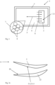
- Fig.1 shows a device 1 for smoothing a component 2, specifically a surface 2.1 of the component 2.
- the component 2 is a blade or a vane of an aircraft engine, see also Fig.3 for illustration.
- the component 2 is placed in a container 3 that is filled with a liquid-solid mixture 4.
- the component 2 is then moved in the liquid-solid mixture 4, thus generating a relative movement 5 between the liquid-solid mixture 4 and the component 2.
- the mixture 4 is made up of a liquid component 7 (in this case, e.g. water, H 2 O 2 , silicates) and spherical solids 8 with a diameter of e.g. 0.5 mm.
- a liquid component 7 in this case, e.g. water, H 2 O 2 , silicates
- spherical solids 8 with a diameter of e.g. 0.5 mm.
- a guide surface 20 is arranged in the mixture 4, which imposes a directional component 21 on the flow 6 towards the surface 2.1 of the component 2.
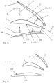
- Fig. 2a -c illustrates (especially in Fig. 2a ), each in one cut (based on Fig.1 the cutting plane is perpendicular to the drawing surface and horizontal).
- the profile shape of component 2 e.g. the blade, can be seen.
- a further guide surface 200 is provided, which also imposes a directional component 210 on the flow 6 towards the component surface 2.1.
- a guide surface 20,200 is thus assigned to both a suction side surface 2.1.1 and a pressure side surface 2.1.2 of the blade.
- Each of the guide surfaces 20,200 is formed by a guide body 22,220, namely a guide plate around which the mixture 5 flows.
- the guide surfaces 20,200 are arranged relative to the component 2 or its surface 2.1 such that a respective distance 25,250 to the surface 2.1 decreases in the flow direction 26. Furthermore, a guide surface distance 27 between the guide surfaces 20,200 also decreases in the flow direction 26.
- the component 2 i.e. the blade
- the component 2 is not flown at its leading edge, but at its trailing edge during smoothing.
- only a single guide body 22 with the guide surface 20 is used, which is assigned to the suction side surface 2.1.1 of the component 2.
- the Fig. 2a-c illustrate different possibilities and options.
- Fig.3 shows a turbomachine 30, specifically a turbofan engine, in an axial section (the section plane includes the longitudinal axis 31).
- the turbomachine 30 is divided into a compressor 32, a combustion chamber 33 and a turbine 34, whereby air drawn in is compressed in the compressor 32.
- the combustion chamber 33 it is burned with kerosene mixed in, and the resulting hot gas is expanded in the turbine 34.
- Both the compressor 32 and the turbine 34 are constructed in several stages.
- the component 2 (the blade smoothed as described above) can be used in both the turbine 34 and the compressor 32, the latter being preferred (due to the high aerodynamic requirements there).
- Component 2 Surface (component surface) 2.1 Suction side surface 2.1.1 Print side area 2.1.2 container 3 Liquid-solid mixture 4 Relative motion 5 flow 6 Liquid component 7 Solids 8th Guide surface 20
- Directional component (to the component surface) 21
- Guide body 22 Distance 25
- Flow direction 26 Guide surface distance 27
- Turbomachine 30 Longitudinal axis 31
- compressor 32 Combustion chamber 33
- turbine 34 Guide surface (other) 200
- Directional component (of the further guide surface) 210 Guide body (further) 220 Distance (of the further guide surface) 250
Landscapes
- Engineering & Computer Science (AREA)
- Mechanical Engineering (AREA)
- General Engineering & Computer Science (AREA)
- Structures Of Non-Positive Displacement Pumps (AREA)
Description
- Die vorliegende Erfindung betrifft ein Verfahren und eine Vorrichtung zum Glätten einer Bauteiloberfläche.
- Zum Glätten von Bauteilen sind unterschiedliche Verfahren bekannt, ein Materialabtrag kann bspw. mit einer geometrisch bestimmten oder unbestimmten Schneide spanend erfolgen. Mit dem Materialabtrag werden Unebenheiten der Oberfläche entfernt, wird diese also geglättet. Beim chemisch-mechanischen Polieren kann dies durch eine Kombination aus chemischer und mechanischer Einwirkung auf die Bauteiloberfläche erfolgen. Auf ein solches Verfahren richtet sich der vorliegende Gegenstand, wobei es im Besonderen um das Glätten von Strömungsmaschinen- bzw. Triebwerksbauteilen geht. Das Dokument
US 5 341 602 A offenbart ein Verfahren sowie eine Vorrichtung, auf welchem jeweils der Oberbegriff der unabhängigen Ansprüche basiert. - Eine Strömungsmaschine kann sich funktional in Verdichter, Brennkammer und Turbine gliedern, wobei im Falle eines Flugtriebwerks angesaugte Luft im Verdichter komprimiert und in der nachgelagerten Brennkammer mit hinzugemischtem Kerosin verbrannt wird. Das entstehende Heißgas, eine Mischung aus Verbrennungsgas und Luft, durchströmt die nachgelagerte Turbine und wird dabei expandiert. Die Turbine und der Verdichter sind in der Regel jeweils mehrstufig aufgebaut, wobei eine jeweilige Stufe einen Leit- und einen Laufschaufelkranz umfasst. Jeder Schaufelkranz ist aus einer Mehrzahl umlaufend aufeinanderfolgender Schaufeln aufgebaut, die je nach Anwendung von dem Verdichter- bzw. dem Heißgas umströmt werden. Ein Glätten dieser Bauteiloberflächen kann bspw. aerodynamisch von Vorteil sein.
- Der vorliegenden Erfindung liegt das technische Problem zugrunde, ein vorteilhaftes Verfahren zum Glätten einer Oberfläche eines Bauteils anzugeben.
- Dies wird erfindungsgemäß mit dem Verfahren gemäß Anspruch 1 gelöst. Dabei wird das Bauteil in ein Behältnis (Bad) mit einem Flüssigkeits-Festkörper-Gemisch gegeben, und es wird eine Relativbewegung zwischen dem Gemisch und dem Bauteil erzeugt. Das Gemisch strömt entlang der zu glättenden Oberfläche, womit sich ein kombiniert chemisch-mechanischer Materialabtrag erreichen lässt, das Bauteil wird chemisch-mechanisch poliert. Erfindungsgemäß wird bzw. ist dabei in dem Bad bzw. Behältnis mit dem Gemisch eine Leitfläche vorgesehen, entlang welcher das Gemisch strömt. Die Leitfläche führt die Strömung und drückt dabei insbesondere die Festkörperkomponente zu der Bauteiloberfläche hin, überlagert ihr also eine Richtungskomponente zu der Bauteiloberfläche.
- Mit der Leitfläche wird das Gemisch und damit insbesondere der Festkörperanteil auf die Oberfläche geführt, sodass dort ein hinreichender Druck für den Materialabtrag erreicht wird. Der Festkörperanteil kann z. B. partikel-, insbesondere kugelförmig vorgesehen sein, wobei die Kugeln aufgrund der Führung dann an der Bauteiloberfläche mit einem hinreichend großen Druck abrollen, um die gewünschte Polierwirkung zu erzielen. Der Festkörperanteil in dem Gemisch kann insbesondere so hoch sein, dass zwischen der Leitfläche und der Oberfläche des Bauteils ein zusammenhängendes Agglomerat der Partikel bzw. Kugeln vorliegt; zwischen Leitfläche und Bauteil bildet sich somit eine Kraftkette, sodass die Partikel/Kugeln zuverlässig gegen die Bauteiloberfläche gedrückt werden. Die Leitfläche kann bspw. einen über die Bauteiloberfläche hinweg gleichmäßigeren Druck ergeben bzw. einstellen helfen, was die Homogenität des Glättungsergebnisses verbessern kann.
- Zur Illustration: würde man bspw. ein Schaufelblatt ohne Leitfläche in das Gemisch geben und in einer der Anordnung im Gaskanal vergleichbaren Weise umströmen (Anströmen an der Vorder- und Abströmen an der Hinterkante), wäre der Druck und damit der Materialabtrag an der Vorderkante hoch. Zur Hinterkante hin würde er jedoch abnehmen, was einen insgesamt ungleichmäßigen Abtrag ergeben würde. Um gleichwohl eine gewisse Vergleichmäßigung zu erreichen, muss das Bauteil ohne Leitblech dann bspw. in unterschiedlichen Orientierungen umströmt werden, was Aufwand bedeutet und die Bearbeitungsdauer erhöht. Mit der Leitfläche lässt sich die Strömung hingegen so einstellen, dass im Idealfall gar keine Umorientierung des Bauteils erforderlich ist, also in einer einzigen Relativanordnung bzw. -orientierung ein gleichmäßiger Materialabtrag erreicht wird.
- Bevorzugte Ausgestaltungen der Erfindung finden sich in den abhängigen Ansprüchen und der gesamten Offenbarung, wobei bei der Darstellung der Merkmale nicht immer im Einzelnen zwischen Verfahrens- und Vorrichtungsaspekten unterschieden wird; jedenfalls implizit ist die Offenbarung hinsichtlich sämtlicher Anspruchskategorien zu lesen. Werden bspw. bestimmte Mittel beschrieben, die in dem Verfahren Anwendung finden, ist dies auch als Offenbarung einer mit den entsprechenden Mitteln ausgestatteten Vorrichtung zur Durchführung des Verfahrens zu verstehen.
- "Ein" und "eine" sind im Rahmen dieser Offenbarung als unbestimmte Artikel und damit ohne ausdrücklich gegenteilige Angabe immer auch als "mindestens ein" bzw. "mindestens eine" zu lesen. In dem Bad können also bspw. auch mehrere Bauteile gleichzeitig angeordnet und geglättet werden. Handelt es sich bei dem Bauteil um ein Schaufelblatt, kann dieses Teil einer einzelnen Schaufel oder eines Mehrfach-Segments sein, im Prinzip kann sogar auch ein kompletter Schaufelkranz bearbeitet werden (Blisk, Blade Integrated Disk).
- Wie bereits erwähnt, kann es sich bei dem Bauteil bevorzugt um ein Schaufelblatt einer Strömungsmaschine handeln, das in deren Gaskanal angeordnet und umströmt wird. Prinzipiell ist auch eine Anwendung im Turbinenbereich denkbar, kann das Schaufelblatt also im Heißgaskanal angeordnet und von Heißgas umströmt werden. Bevorzugt ist eine Anwendung im Verdichterbereich, wird das Schaufelblatt also im Verdichtergaskanal von Verdichtergas umströmt. Hierbei können die Vorteile des erfindungsgemäßen Verfahrens im Besonderen zu Tragen kommen, kann nämlich die homogen geglättete Bauteiloberfläche bspw. einem Strömungsabriss vorbeugen helfen.
- In bevorzugter Ausgestaltung ist die Leitfläche eine Seitenfläche eines Leitkörpers, der in dem Bad umströmt wird. Letzteres meint, dass das Flüssigkeits-Festkörper-Gemisch nicht nur entlang der Leitfläche strömt, sondern auch entlang einer der Leitfläche entgegengesetzten Seitenfläche des Leitkörpers. Der Leitkörper ist bevorzugt aus Metall vorgesehen, es kann sich insbesondere um ein Leitblech handeln (einfache und flexible Herstellung).
- In bevorzugter Ausgestaltung hat die Bauteiloberfläche in einer Schnittebene betrachtet einen gekrümmten Verlauf und ist die Leitfläche in derselben Schnittebene betrachtet komplementär gekrümmt. Ist die Oberfläche also bspw. konvex, so erstreckt sich die Leitfläche konkav, und im Falle einer konkaven Bauteiloberfläche erstreckt sie sich konvex. Die besagte Schnittebene liegt bevorzugt parallel zur Umströmungsrichtung, im Falle des Schaufelblatts kann es sich bspw. um eine Tangential-Schnittebene handeln (in dieser wird das Schaufelblattprofil betrachtet, die Schnittebene liegt tangential an einem Umlauf um die Längs- bzw. Drehachse der Strömungsmaschine).
- In bevorzugter Ausgestaltung ist die Leitfläche derart zur Bauteiloberfläche angeordnet, dass ein Abstand dazwischen in Strömungsrichtung abnimmt. Konkret wird der Abstand im Schnitt betrachtet (vgl. den vorherigen Absatz bezüglich der Schnittebene) senkrecht zu den Stromlinien zwischen der Oberfläche und der Leitfläche genommen. Bevorzugt kann ein in Strömungsrichtung stetig (ohne Sprünge/Stufen) abnehmender Abstand sein, was hinsichtlich der gewünschten Homogenisierung Vorteile bieten kann.
- Erfindungsgemäß ist in dem Bad eine weitere Leitfläche vorgesehen, die ebenfalls von einem Leitkörper, insbesondere einem Leitblech gebildet werden kann. Das Bauteil ist bzw. wird dabei, bezogen auf eine Richtung senkrecht zur Strömungsrichtung, zwischen den Leitflächen angeordnet. Die Strömung wird dann von der einen Leitfläche auf einen Oberflächenbereich des Bauteils geführt und von der anderen Leitfläche auf einen dazu entgegengesetzten Oberflächenbereich. Im Falle des Schaufelblatts kann die eine Leitfläche der Saug- und die andere der Druckseitenfläche zugeordnet sein.
- Erfindungsgemäß sind die Leitflächen, zwischen denen das Bauteil platziert ist, relativ zueinander derart angeordnet, dass ein Abstand dazwischen in Strömungsrichtung abnimmt. Konkret wird dieser Leitflächen-Abstand im Schnitt betrachtet senkrecht zu den Stromlinien zwischen den Leitflächen genommen, vgl. auch die vorstehenden Anmerkungen. Wird also bspw. ein Schaufelblatt geglättet und dazu an der Vorderkante angeströmt, nimmt der Abstand zwischen den beidseits davon angeordneten Leitflächen von der Vorder- zur Hinterkante hin ab. Bevorzugt nimmt dabei auch jeweils der Abstand zwischen Leitfläche und jeweiligem Oberflächenbereich (Saug- bzw. Druckseitenfläche) ab, siehe vorne.
- Alternativ zu einem Schaufelblatt kann es sich bei dem Bauteil im Allgemeinen bspw. auch um eine Verkleidung, also ein Fairing handeln. Ebenso lassen sich Kanalplatten (Panels) glätten und damit hinsichtlich der Umströmung im Gaskanal optimieren. Bevorzugt ist das Bauteil jedoch ein Schaufelblatt. Zur Erzeugung der Relativbewegung zwischen dem Flüssigkeits-Festkörper-Gemisch und dem Bauteil könnte im Allgemeinen auch eine Düse in dem Bad vorgesehen sein, durch welche das Gemisch gepumpt und damit auf das Bauteil beschleunigt wird. Letzteres würde in diesem Fall in einem ortsfesten Koordinatensystem betrachtet, also in der Bearbeitungsmaschine und damit bspw. auch in der Montage- bzw. Fertigungshalle ruhen. In bevorzugter Ausgestaltung wird die Relativbewegung jedoch erreicht, indem das Bauteil durch das Flüssigkeits-Festkörper-Gemisch bewegt wird. In einem ortsfesten Koordinatensystem betrachtet wird dann also das Bauteil bewegt, es wird durch das Gemisch gezogen bzw. geschoben. In bevorzugter Ausbildung wird bzw. werden dabei die Leitflächen bzw. Leitkörper/Leitbleche gemeinsam mit dem Bauteil durch das Bad bewegt. Sie können bspw. an einer Halterung angeordnet sein, in welche das Bauteil gesetzt und die dann samt Bauteil durch das Gemisch bewegt wird.
- Das Flüssigkeits-Festkörper-Gemisch kann bspw. auf Wasserbasis vorgesehen sein. Je nach Material des Bauteils kann es bspw. eine Säure aufweisen, z. B. Wasserstoffperoxid. Ferner kann die Flüssigkomponente bspw. Silikate aufweisen. Der Festkörperbestandteil ist bevorzugt partikel- bzw. kugelförmig vorgesehen, insbesondere in Form von Glas- oder Metallkugeln. Diese können bspw. einen Durchmesser im Mikro- bzw. Millimeterbereich haben, etwa von mindestens 200 µm und z. B. höchstens 2 mm, also bspw. von rund 0,5 mm.
- Die Erfindung betrifft auch eine Vorrichtung zum Glätten einer Bauteiloberfläche gemäß Anspruch 9.
- Im Folgenden wird die Erfindung anhand eines Ausführungsbeispiels näher erläutert, wobei die einzelnen Merkmale im Rahmen der nebengeordneten Ansprüche auch in anderer Kombination erfindungswesentlich sein können und auch weiterhin nicht im Einzelnen zwischen den unterschiedlichen Anspruchskategorien unterschieden wird. Im Einzelnen zeigt
- Figur 1
- eine Vorrichtung zur Durchführung des erfindungsgemäßen Verfahrens in einer schematischen, teilweise geschnittenen Seitenansicht;
- Figur 2a-b
- verschiedene Möglichkeiten zur Anordnung von Leitflächen bzw. - körpern zur Strömungsführung in der Vorrichtung gemäß
Figur 1 ; - Figur 3
- ein Triebwerk in einem Axialschnitt zur Illustration möglicher Anwendungen.
-
Fig. 1 zeigt eine Vorrichtung 1 zum Glätten eines Bauteils 2, konkret einer Oberfläche 2.1 des Bauteils 2. Bei dem Bauteil 2 handelt es sich vorliegend um eine Schaufel bzw. ein Schaufelblatt eines Flugtriebwerks, vgl. auchFig. 3 zur Illustration. Zum Glätten ist bzw. wird das Bauteil 2 in ein Behältnis 3 gegeben, das mit einem Flüssigkeits-Festkörper-Gemisch 4 gefüllt ist. - Das Bauteil 2 wird dann in dem Flüssigkeits-Festkörper-Gemisch 4 bewegt, es wird also eine Relativbewegung 5 zwischen dem Flüssigkeits-Festkörper-Gemisch 4 und dem Bauteil 2 erzeugt. Dadurch stellt sich eine Strömung 6 des Flüssigkeits-Festkörper-Gemischs 4 entlang der Oberfläche 2.1 des Bauteils 2 ein. Wie die vergrößerte Darstellung illustriert, ist das Gemisch 4 aus einer Flüssigkomponente 7 (vorliegend z. B. Wasser, H2O2, Silikate) und kugelförmigen Festkörpern 8 mit einem Durchmesser von z. B. 0,5 mm aufgebaut. Wenn das Gemisch 4 aufgrund der Relativbewegung 5 entlang der Oberfläche 2.1 strömt, rollen die Kugeln mit gewissem Druck an der Oberfläche 2.1 ab.
- Um einen über die Oberfläche 2.1 gleichmäßigeren Druck zu erreichen, ist erfindungsgemäß eine Leitfläche 20 in dem Gemisch 4 angeordnet, welche der Strömung 6 eine Richtungskomponente 21 zu der Oberfläche 2.1 des Bauteils 2 hin auferlegt. Dies ist in den
Fig. 2a -c veranschaulicht (im Besonderen inFig. 2a ), und zwar jeweils in einem Schnitt (bezogen aufFig. 1 liegt die Schnittebene senkrecht zur Zeichenfläche und horizontal). In diesen Schnitten ist die Profilform des Bauteils 2, also z. B. des Schaufelblatts, zu erkennen. - Bei den Varianten gemäß den
Fig. 2a,b ist jeweils noch eine weitere Leitfläche 200 vorgesehen, welche der Strömung 6 ebenfalls eine Richtungskomponente 210 zu der Bauteiloberfläche 2.1 hin auferlegt. Damit ist sowohl einer Saugseitenfläche 2.1.1 als auch einer Druckseitenfläche 2.1.2 des Schaufelblatts jeweils eine Leitfläche 20,200 zugeordnet. Jede der Leitflächen 20,200 wird jeweils von einem Leitkörper 22,220 gebildet, nämlich einem von dem Gemisch 5 umspülten Leitblech. - Die Leitflächen 20,200 sind relativ zu dem Bauteil 2 bzw. dessen Oberfläche 2.1 so angeordnet, dass ein jeweiliger Abstand 25,250 zur Oberfläche 2.1 in Strömungsrichtung 26 abnimmt. Ferner nimmt auch ein Leitflächen-Abstand 27 zwischen den Leitflächen 20,200 in Strömungsrichtung 26 ab.
- In der in
Fig. 2c dargestellten Situation wird das Bauteil 2, also das Schaufelblatt, beim Glätten nicht an seiner Vorder-, sondern an seiner Hinterkante angeströmt. Im Übrigen findet in diesem Fall auch nur ein einzelner Leitkörper 22 mit der Leitfläche 20 Anwendung, die der Saugseitenfläche 2.1.1 des Bauteils 2 zugeordnet ist. Generell sollen dieFig. 2a-c unterschiedliche Möglichkeiten und Optionen illustrieren. -
Fig. 3 zeigt eine Strömungsmaschine 30, konkret ein Mantelstromtriebwerk, in einem Axialschnitt (die Schnittebene beinhaltet die Längsachse 31). Funktional gliedert sich die Strömungsmaschine 30 in Verdichter 32, Brennkammer 33 und Turbine 34, wobei im Verdichter 32 angesaugte Luft komprimiert wird. In der Brennkammer 33 wird sie mit hinzugemischtem Kerosin verbrannt, das entstehende Heißgas wird in der Turbine 34 expandiert. Sowohl der Verdichter 32 also die Turbine 34 sind jeweils mehrstufig aufgebaut. Das Bauteil 2 (das gemäß der vorstehenden Schilderung geglättete Schaufelblatt) kann sowohl in der Turbine 34 also im Verdichter 32 Anwendung finden, bevorzugt ist Letzteres (wegen der hohen aerodynamischen Anforderungen dort). -
Bauteil 2 Oberfläche (Bauteiloberfläche) 2.1 Saugseitenfläche 2.1.1 Druckseitenfläche 2.1.2 Behältnis 3 Flüssigkeits-Festkörper-Gemisch 4 Relativbewegung 5 Strömung 6 Flüssigkomponente 7 Festkörper 8 Leitfläche 20 Richtungskomponente (zur Bauteiloberfläche) 21 Leitkörper 22 Abstand 25 Strömungsrichtung 26 Leitflächen-Abstand 27 Strömungsmaschine 30 Längsachse 31 Verdichter 32 Brennkammer 33 Turbine 34 Leitfläche (weitere) 200 Richtungskomponente (der weiteren Leitfläche) 210 Leitkörper (weiterer) 220 Abstand (der weiteren Leitfläche) 250
Claims (9)
- Verfahren zum Glätten einer Oberfläche (2.1) eines Bauteils (2) welches zum Anordnen in einem Gaskanal einer Strömungsmaschine (30) ausgelegt ist und das Bauteil (2) vorzugsweise ein Schaufelblatt für eine Strömungsmaschine (30) ist, wobei die Oberfläche (2.1) eine dem Gaskanal zugewandte Oberfläche (2.1) ist, bei welchem Verfahren- das Bauteil (2) in ein Behältnis (3) mit einem Flüssigkeits-Festkörper-Gemisch (4) gegeben wird,- eine Relativbewegung (5) zwischen dem Flüssigkeits-Festkörper-Gemisch (4) und dem Bauteil (2) erzeugt wird, also eine Strömung (6) des Flüssigkeits-Festkörper-Gemischs (4) entlang der Oberfläche (2.1);wobei in dem Flüssigkeits-Festkörper-Gemisch (4) eine Leitfläche (20) vorgesehen ist, entlang welcher das Flüssigkeits-Festkörper-Gemisch (4) strömt, wobei der Strömung (6) eine Richtungskomponente (21) zu der Oberfläche (2.1) hin auferlegt wird undbei welchem in dem Flüssigkeits-Festkörper-Gemisch (4) eine weitere Leitfläche (200) vorgesehen ist, entlang welcher das Flüssigkeits-Festkörper-Gemisch (4) strömt, dadurch gekennzeichnet, dassdas Bauteil (2) zwischen den Leitflächen (20,200) angeordnet ist und bei welchem die Leitflächen (20,200) relativ zueinander derart angeordnet sind, dass ein Leitflächen-Abstand (27), der in einer Schnittebene betrachtet senkrecht zu einem Stromlinienprofil zwischen den Leitflächen (20,200) genommen wird, in Strömungsrichtung (26) abnimmt.
- Verfahren nach Anspruch 1, bei welchem die Leitfläche (20) eine Seitenfläche eines Leitkörpers (22) ist, der in dem Flüssigkeits-Festkörper-Gemisch (4) umströmt wird, bei dem das Flüssigkeits-Festkörper-Gemisch (4) also auch entlang einer der Leitfläche (20) entgegengesetzten Seitenfläche strömt.
- Verfahren nach Anspruch 1 oder 2, bei welchem die Oberfläche (2.1) des Bauteils (2) in einer Schnittebene betrachtet einen gekrümmten Verlauf hat und die Leitfläche (20) in derselben Schnittebene betrachtet einen komplementär gekrümmten Verlauf hat.
- Verfahren nach einem der vorstehenden Ansprüche, bei welchem die Leitfläche (20) derart relativ zu der Oberfläche (2.1) angeordnet ist, dass ein Abstand (25), der in einer Schnittebene betrachtet senkrecht zu einem Stromlinienprofil zwischen der Oberfläche (2.1) und der Leitfläche (20) genommen wird, in Strömungsrichtung (26) abnimmt.
- Verfahren nach Anspruch 1, bei welchem die Oberfläche (2.1) des Bauteils (2) eine Saugseitenfläche und eine Druckseitenfläche umfasst, wobei sowohl der Saugseitenfläche als auch der Druckseitenfläche jeweils eine Leitfläche (20,200) in dem Flüssigkeits-Festkörper-Gemisch (4) zugeordnet ist.
- Verfahren nach einem der vorstehenden Ansprüche, bei welchem das Bauteil (2) zur Erzeugung der Relativbewegung (5) in einem ortsfesten Koordinatensystem bewegt wird, also das Bauteil (2) durch das Flüssigkeits-Festkörper-Gemisch (4) bewegt wird.
- Verfahren nach Anspruch 6, bei welchem die Leitfläche (20) bzw. Leitflächen (20,200) gemeinsam mit dem Bauteil (2) durch das Flüssigkeits-Festkörper-Gemisch (4) bewegt wird bzw. werden.
- Verfahren nach einem der vorstehenden Ansprüche, bei welchem das Flüssigkeits-Festkörper-Gemisch (4) auf Wasserbasis mit kugelförmigen Festkörpern (8) vorgesehen ist.
- Vorrichtung zum Glätten einer Oberfläche (2.1) des Bauteils (2) zur Durchführen eines Verfahrens nach einem der vorstehenden Ansprüche, dadurch gekennzeichnet, dass die Vorrichtung aufweist:- ein Behältnis (3) zum Aufnehmen des Flüssigkeits-Festkörper-Gemischs (4) und zum Anordnen des Bauteils (2);- eine Bewegungseinrichtung zum Erzeugen der Relativbewegung (5) zwischen dem Flüssigkeits-Festkörper-Gemisch (4) und dem Bauteil (2);- eine Leitfläche (20) in dem Behältnis (3), um der Strömung (6) die Richtungskomponente (21) zu der Oberfläche (2.1) hin aufzuerlegen und bei welchem in dem Flüssigkeits-Festkörper-Gemisch (4) eine weitere Leitfläche (200) vorgesehen ist, entlang welcher das Flüssigkeits-Festkörper-Gemisch (4) strömt, zum Anordnen des Bauteils (2) zwischen den Leitflächen (20,200), dadurch gekennzeichnet, dass die Leitflächen (20,200) relativ zueinander derart angeordnet sind, dass ein Leitflächen-Abstand (27), der in einer Schnittebene betrachtet senkrecht zu einem Stromlinienprofil zwischen den Leitflächen (20,200) genommen wird, in Strömungsrichtung (26) abnimmt.
Applications Claiming Priority (1)
| Application Number | Priority Date | Filing Date | Title |
|---|---|---|---|
| DE102019201656.1A DE102019201656A1 (de) | 2019-02-08 | 2019-02-08 | Verfahren zum glätten einer oberfläche eines bauteils |
Publications (2)
| Publication Number | Publication Date |
|---|---|
| EP3733348A1 EP3733348A1 (de) | 2020-11-04 |
| EP3733348B1 true EP3733348B1 (de) | 2024-06-26 |
Family
ID=69526148
Family Applications (1)
| Application Number | Title | Priority Date | Filing Date |
|---|---|---|---|
| EP20156017.4A Active EP3733348B1 (de) | 2019-02-08 | 2020-02-07 | Verfahren und vorrichtung zum glätten einer oberfläche eines bauteils |
Country Status (3)
| Country | Link |
|---|---|
| US (1) | US11612977B2 (de) |
| EP (1) | EP3733348B1 (de) |
| DE (1) | DE102019201656A1 (de) |
Families Citing this family (2)
| Publication number | Priority date | Publication date | Assignee | Title |
|---|---|---|---|---|
| CN114453990B (zh) * | 2022-04-12 | 2022-08-19 | 徐州中顺尚奕机械制造有限公司 | 混合清洁型热膨胀式金属表面全方位无损除锈加工装置 |
| DE102022209051A1 (de) | 2022-08-31 | 2024-02-29 | Zf Friedrichshafen Ag | Verfahren und Steuergerät zum Betreiben eines Antriebsstrangs eines Fahrzeugs |
Family Cites Families (17)
| Publication number | Priority date | Publication date | Assignee | Title |
|---|---|---|---|---|
| JPS5216098A (en) * | 1975-07-28 | 1977-02-07 | Sumitomo Electric Ind Ltd | Scraping device of scal on wire |
| US5341602A (en) * | 1993-04-14 | 1994-08-30 | Williams International Corporation | Apparatus for improved slurry polishing |
| FR2713974B1 (fr) | 1993-12-22 | 1996-01-19 | Snecma | Dispositif de grenaillage de surfaces non accessibles par une canalisation droite. |
| EP0922530B1 (de) * | 1997-12-10 | 2005-03-23 | Shuji Kawasaki | Gleitschleifvorrichtung |
| ES2178495T3 (es) * | 1998-11-14 | 2002-12-16 | Mtu Aero Engines Gmbh | Sistema de mecanizacion de precision de piezas componentes simetricas rotativas. |
| JP4059421B2 (ja) | 2000-10-31 | 2008-03-12 | 新東工業株式会社 | ショットピ−ニング装置 |
| US6464570B1 (en) | 2001-07-17 | 2002-10-15 | General Electric Company | Omnidirectional shot nozzle |
| JP3997315B2 (ja) * | 2002-06-14 | 2007-10-24 | 株式会社Ihi | ブレード表面研摩装置のブレード固定治具 |
| US6962522B1 (en) * | 2004-05-12 | 2005-11-08 | Bbf Yamate Corporation | Barrel polishing device |
| JP5066430B2 (ja) | 2007-11-20 | 2012-11-07 | 日本発條株式会社 | ショットピーニング用反射部材およびそれを用いたショットピーニング方法 |
| DE102008017475A1 (de) * | 2008-04-03 | 2009-10-08 | Siegrid Peggy Seltmann | Verfahren zur Oberflächenbehandlung von metallischen Werkstücken |
| US20110244770A1 (en) * | 2010-04-05 | 2011-10-06 | Boutaghou Llc | Abrasive slurry formulations containing nano and micro spheres additives or self-assembled monolayers |
| US9421661B2 (en) * | 2013-04-30 | 2016-08-23 | United Technologies Corporation | Airfoil edge form transfer grinding tool |
| SI24359A (sl) * | 2013-05-14 | 2014-11-28 | Univerza V Ljubljani | Priprave in postopki poliranja z abrazivnim tokom |
| EP2848367B1 (de) | 2013-09-11 | 2016-03-23 | Rolls-Royce Deutschland Ltd & Co KG | Vorrichtung und Verfahren zum Strahlhämmern von Schaufelmontagebereichen auf einer Rotoranordnungsscheibe |
| JP6264347B2 (ja) | 2015-09-10 | 2018-01-24 | ダイキン工業株式会社 | 空調室内機 |
| GB201805763D0 (en) * | 2018-04-06 | 2018-05-23 | Rolls Royce Plc | A method and apparatus for finishing an internal channel of a component |
-
2019
- 2019-02-08 DE DE102019201656.1A patent/DE102019201656A1/de active Pending
-
2020
- 2020-02-07 US US16/784,704 patent/US11612977B2/en active Active
- 2020-02-07 EP EP20156017.4A patent/EP3733348B1/de active Active
Also Published As
| Publication number | Publication date |
|---|---|
| DE102019201656A1 (de) | 2020-08-13 |
| EP3733348A1 (de) | 2020-11-04 |
| US20200254581A1 (en) | 2020-08-13 |
| US11612977B2 (en) | 2023-03-28 |
Similar Documents
| Publication | Publication Date | Title |
|---|---|---|
| EP2093021B1 (de) | Verfahren und Vorrichtung zum Kugelstrahlverfestigen von Bliskschaufeln | |
| EP2353772B1 (de) | Verfahren und Vorrichtung zur Oberflächenverfestigung von Bliskschaufeln | |
| EP3733348B1 (de) | Verfahren und vorrichtung zum glätten einer oberfläche eines bauteils | |
| DE3728946C2 (de) | ||
| EP1774179B1 (de) | Verdichterschaufel | |
| EP2099585B1 (de) | Vorrichtung und verfahren zum oberflächenstrahlen eines bauteils einer gasturbine | |
| EP1617972B1 (de) | Verfahren zum verrunden von kanten an bauteilen | |
| EP2125292B1 (de) | Verfahren und vorrichtung zum oberflächenstrahlen eines teilelements eines bauteils einer gasturbine | |
| WO2013107489A1 (de) | Verfahren und vorrichtung zur stabilisierung eines verdichterstroms | |
| DE3444847C1 (de) | Verfahren zum Vergleichmaessigen der Teilchengroesse feinteiligen Pulvers,Vorrichtung zur Durchfuehrung des Verfahrens und Verwendung des Pulvers | |
| DE102014222530A1 (de) | Bandabweiser und Walzenanordnung | |
| DE102014224920A1 (de) | Vorrichtung zum Rekonturieren einer Gasturbinenschaufel | |
| DE102016213075A1 (de) | Verfahren zur Oberflächenbearbeitung, Verfahren zur Herstellung eines Motorblockes, Vorrichtung zur Oberflächenbearbeitung und Kraftfahrzeug | |
| DE10348805B4 (de) | Verfahren zur Erzeugung eines Wasserabrasivstrahls | |
| EP4438186A1 (de) | Zweistoffsprühventil und zweistoffsprühvorrichtung sowie deren verwendungen und maschine zum bearbeiten eines plattenförmigen werkstücks | |
| EP3235593B1 (de) | Formgebungswerkzeug zum trennen von werkstoffen | |
| EP2808124A1 (de) | Verfahren und Vorrichtung zur Bearbeitung von Turbinenschaufeln | |
| DE102005061401A1 (de) | Verfahren zur Mikrostrukturierung einer Oberfläche eines Werkstücks | |
| EP2454451A2 (de) | Kopplungselement zur mechanischen kopplung von schaufeln und rotor | |
| EP1954421A1 (de) | Verfahren zum herstellen von metallischen bauteilen, insbesondere für turbomaschinen, mit kleinen kantenradien, sowie damit hergestelltes bauteil | |
| EP3486494B1 (de) | Radialgebläsegehäuse und radialgebläse | |
| WO2024165356A1 (de) | Vorrichtung zum elektrochemischen abtragen | |
| EP4431234A1 (de) | Verfahren und vorrichtung zur bearbeitung einer hartstoffbeschichteten werkstückfläche eines rotationssymmetrischen werkstücks | |
| DE102010017720B4 (de) | Hochdruck-Schneideinrichtung | |
| DE102019217394A1 (de) | Leitschaufelanordnung für eine strömungsmaschine |
Legal Events
| Date | Code | Title | Description |
|---|---|---|---|
| PUAI | Public reference made under article 153(3) epc to a published international application that has entered the european phase |
Free format text: ORIGINAL CODE: 0009012 |
|
| STAA | Information on the status of an ep patent application or granted ep patent |
Free format text: STATUS: THE APPLICATION HAS BEEN PUBLISHED |
|
| AK | Designated contracting states |
Kind code of ref document: A1 Designated state(s): AL AT BE BG CH CY CZ DE DK EE ES FI FR GB GR HR HU IE IS IT LI LT LU LV MC MK MT NL NO PL PT RO RS SE SI SK SM TR |
|
| AX | Request for extension of the european patent |
Extension state: BA ME |
|
| STAA | Information on the status of an ep patent application or granted ep patent |
Free format text: STATUS: REQUEST FOR EXAMINATION WAS MADE |
|
| 17P | Request for examination filed |
Effective date: 20210416 |
|
| RBV | Designated contracting states (corrected) |
Designated state(s): AL AT BE BG CH CY CZ DE DK EE ES FI FR GB GR HR HU IE IS IT LI LT LU LV MC MK MT NL NO PL PT RO RS SE SI SK SM TR |
|
| GRAP | Despatch of communication of intention to grant a patent |
Free format text: ORIGINAL CODE: EPIDOSNIGR1 |
|
| STAA | Information on the status of an ep patent application or granted ep patent |
Free format text: STATUS: GRANT OF PATENT IS INTENDED |
|
| INTG | Intention to grant announced |
Effective date: 20240117 |
|
| GRAS | Grant fee paid |
Free format text: ORIGINAL CODE: EPIDOSNIGR3 |
|
| GRAA | (expected) grant |
Free format text: ORIGINAL CODE: 0009210 |
|
| STAA | Information on the status of an ep patent application or granted ep patent |
Free format text: STATUS: THE PATENT HAS BEEN GRANTED |
|
| AK | Designated contracting states |
Kind code of ref document: B1 Designated state(s): AL AT BE BG CH CY CZ DE DK EE ES FI FR GB GR HR HU IE IS IT LI LT LU LV MC MK MT NL NO PL PT RO RS SE SI SK SM TR |
|
| REG | Reference to a national code |
Ref country code: GB Ref legal event code: FG4D Free format text: NOT ENGLISH |
|
| REG | Reference to a national code |
Ref country code: CH Ref legal event code: EP |
|
| REG | Reference to a national code |
Ref country code: DE Ref legal event code: R096 Ref document number: 502020008342 Country of ref document: DE |
|
| PG25 | Lapsed in a contracting state [announced via postgrant information from national office to epo] |
Ref country code: BG Free format text: LAPSE BECAUSE OF FAILURE TO SUBMIT A TRANSLATION OF THE DESCRIPTION OR TO PAY THE FEE WITHIN THE PRESCRIBED TIME-LIMIT Effective date: 20240626 |
|
| PG25 | Lapsed in a contracting state [announced via postgrant information from national office to epo] |
Ref country code: FI Free format text: LAPSE BECAUSE OF FAILURE TO SUBMIT A TRANSLATION OF THE DESCRIPTION OR TO PAY THE FEE WITHIN THE PRESCRIBED TIME-LIMIT Effective date: 20240626 Ref country code: HR Free format text: LAPSE BECAUSE OF FAILURE TO SUBMIT A TRANSLATION OF THE DESCRIPTION OR TO PAY THE FEE WITHIN THE PRESCRIBED TIME-LIMIT Effective date: 20240626 |
|
| REG | Reference to a national code |
Ref country code: LT Ref legal event code: MG9D |
|
| PG25 | Lapsed in a contracting state [announced via postgrant information from national office to epo] |
Ref country code: GR Free format text: LAPSE BECAUSE OF FAILURE TO SUBMIT A TRANSLATION OF THE DESCRIPTION OR TO PAY THE FEE WITHIN THE PRESCRIBED TIME-LIMIT Effective date: 20240927 |
|
| PG25 | Lapsed in a contracting state [announced via postgrant information from national office to epo] |
Ref country code: LV Free format text: LAPSE BECAUSE OF FAILURE TO SUBMIT A TRANSLATION OF THE DESCRIPTION OR TO PAY THE FEE WITHIN THE PRESCRIBED TIME-LIMIT Effective date: 20240626 |
|
| REG | Reference to a national code |
Ref country code: NL Ref legal event code: MP Effective date: 20240626 |
|
| PG25 | Lapsed in a contracting state [announced via postgrant information from national office to epo] |
Ref country code: NO Free format text: LAPSE BECAUSE OF FAILURE TO SUBMIT A TRANSLATION OF THE DESCRIPTION OR TO PAY THE FEE WITHIN THE PRESCRIBED TIME-LIMIT Effective date: 20240926 Ref country code: LV Free format text: LAPSE BECAUSE OF FAILURE TO SUBMIT A TRANSLATION OF THE DESCRIPTION OR TO PAY THE FEE WITHIN THE PRESCRIBED TIME-LIMIT Effective date: 20240626 Ref country code: HR Free format text: LAPSE BECAUSE OF FAILURE TO SUBMIT A TRANSLATION OF THE DESCRIPTION OR TO PAY THE FEE WITHIN THE PRESCRIBED TIME-LIMIT Effective date: 20240626 Ref country code: GR Free format text: LAPSE BECAUSE OF FAILURE TO SUBMIT A TRANSLATION OF THE DESCRIPTION OR TO PAY THE FEE WITHIN THE PRESCRIBED TIME-LIMIT Effective date: 20240927 Ref country code: FI Free format text: LAPSE BECAUSE OF FAILURE TO SUBMIT A TRANSLATION OF THE DESCRIPTION OR TO PAY THE FEE WITHIN THE PRESCRIBED TIME-LIMIT Effective date: 20240626 Ref country code: BG Free format text: LAPSE BECAUSE OF FAILURE TO SUBMIT A TRANSLATION OF THE DESCRIPTION OR TO PAY THE FEE WITHIN THE PRESCRIBED TIME-LIMIT Effective date: 20240626 Ref country code: RS Free format text: LAPSE BECAUSE OF FAILURE TO SUBMIT A TRANSLATION OF THE DESCRIPTION OR TO PAY THE FEE WITHIN THE PRESCRIBED TIME-LIMIT Effective date: 20240926 |
|
| PG25 | Lapsed in a contracting state [announced via postgrant information from national office to epo] |
Ref country code: NL Free format text: LAPSE BECAUSE OF FAILURE TO SUBMIT A TRANSLATION OF THE DESCRIPTION OR TO PAY THE FEE WITHIN THE PRESCRIBED TIME-LIMIT Effective date: 20240626 |
|
| PG25 | Lapsed in a contracting state [announced via postgrant information from national office to epo] |
Ref country code: NL Free format text: LAPSE BECAUSE OF FAILURE TO SUBMIT A TRANSLATION OF THE DESCRIPTION OR TO PAY THE FEE WITHIN THE PRESCRIBED TIME-LIMIT Effective date: 20240626 |
|
| PG25 | Lapsed in a contracting state [announced via postgrant information from national office to epo] |
Ref country code: PT Free format text: LAPSE BECAUSE OF FAILURE TO SUBMIT A TRANSLATION OF THE DESCRIPTION OR TO PAY THE FEE WITHIN THE PRESCRIBED TIME-LIMIT Effective date: 20241028 |
|
| PG25 | Lapsed in a contracting state [announced via postgrant information from national office to epo] |
Ref country code: PT Free format text: LAPSE BECAUSE OF FAILURE TO SUBMIT A TRANSLATION OF THE DESCRIPTION OR TO PAY THE FEE WITHIN THE PRESCRIBED TIME-LIMIT Effective date: 20241028 |
|
| PG25 | Lapsed in a contracting state [announced via postgrant information from national office to epo] |
Ref country code: PL Free format text: LAPSE BECAUSE OF FAILURE TO SUBMIT A TRANSLATION OF THE DESCRIPTION OR TO PAY THE FEE WITHIN THE PRESCRIBED TIME-LIMIT Effective date: 20240626 |
|
| PG25 | Lapsed in a contracting state [announced via postgrant information from national office to epo] |
Ref country code: EE Free format text: LAPSE BECAUSE OF FAILURE TO SUBMIT A TRANSLATION OF THE DESCRIPTION OR TO PAY THE FEE WITHIN THE PRESCRIBED TIME-LIMIT Effective date: 20240626 |
|
| PG25 | Lapsed in a contracting state [announced via postgrant information from national office to epo] |
Ref country code: IS Free format text: LAPSE BECAUSE OF FAILURE TO SUBMIT A TRANSLATION OF THE DESCRIPTION OR TO PAY THE FEE WITHIN THE PRESCRIBED TIME-LIMIT Effective date: 20241026 |
|
| PG25 | Lapsed in a contracting state [announced via postgrant information from national office to epo] |
Ref country code: CZ Free format text: LAPSE BECAUSE OF FAILURE TO SUBMIT A TRANSLATION OF THE DESCRIPTION OR TO PAY THE FEE WITHIN THE PRESCRIBED TIME-LIMIT Effective date: 20240626 |
|
| PG25 | Lapsed in a contracting state [announced via postgrant information from national office to epo] |
Ref country code: SK Free format text: LAPSE BECAUSE OF FAILURE TO SUBMIT A TRANSLATION OF THE DESCRIPTION OR TO PAY THE FEE WITHIN THE PRESCRIBED TIME-LIMIT Effective date: 20240626 Ref country code: RO Free format text: LAPSE BECAUSE OF FAILURE TO SUBMIT A TRANSLATION OF THE DESCRIPTION OR TO PAY THE FEE WITHIN THE PRESCRIBED TIME-LIMIT Effective date: 20240626 |
|
| PG25 | Lapsed in a contracting state [announced via postgrant information from national office to epo] |
Ref country code: ES Free format text: LAPSE BECAUSE OF FAILURE TO SUBMIT A TRANSLATION OF THE DESCRIPTION OR TO PAY THE FEE WITHIN THE PRESCRIBED TIME-LIMIT Effective date: 20240626 Ref country code: SM Free format text: LAPSE BECAUSE OF FAILURE TO SUBMIT A TRANSLATION OF THE DESCRIPTION OR TO PAY THE FEE WITHIN THE PRESCRIBED TIME-LIMIT Effective date: 20240626 |
|
| PG25 | Lapsed in a contracting state [announced via postgrant information from national office to epo] |
Ref country code: SM Free format text: LAPSE BECAUSE OF FAILURE TO SUBMIT A TRANSLATION OF THE DESCRIPTION OR TO PAY THE FEE WITHIN THE PRESCRIBED TIME-LIMIT Effective date: 20240626 Ref country code: SK Free format text: LAPSE BECAUSE OF FAILURE TO SUBMIT A TRANSLATION OF THE DESCRIPTION OR TO PAY THE FEE WITHIN THE PRESCRIBED TIME-LIMIT Effective date: 20240626 Ref country code: RO Free format text: LAPSE BECAUSE OF FAILURE TO SUBMIT A TRANSLATION OF THE DESCRIPTION OR TO PAY THE FEE WITHIN THE PRESCRIBED TIME-LIMIT Effective date: 20240626 Ref country code: PL Free format text: LAPSE BECAUSE OF FAILURE TO SUBMIT A TRANSLATION OF THE DESCRIPTION OR TO PAY THE FEE WITHIN THE PRESCRIBED TIME-LIMIT Effective date: 20240626 Ref country code: IS Free format text: LAPSE BECAUSE OF FAILURE TO SUBMIT A TRANSLATION OF THE DESCRIPTION OR TO PAY THE FEE WITHIN THE PRESCRIBED TIME-LIMIT Effective date: 20241026 Ref country code: ES Free format text: LAPSE BECAUSE OF FAILURE TO SUBMIT A TRANSLATION OF THE DESCRIPTION OR TO PAY THE FEE WITHIN THE PRESCRIBED TIME-LIMIT Effective date: 20240626 Ref country code: EE Free format text: LAPSE BECAUSE OF FAILURE TO SUBMIT A TRANSLATION OF THE DESCRIPTION OR TO PAY THE FEE WITHIN THE PRESCRIBED TIME-LIMIT Effective date: 20240626 Ref country code: CZ Free format text: LAPSE BECAUSE OF FAILURE TO SUBMIT A TRANSLATION OF THE DESCRIPTION OR TO PAY THE FEE WITHIN THE PRESCRIBED TIME-LIMIT Effective date: 20240626 |
|
| PG25 | Lapsed in a contracting state [announced via postgrant information from national office to epo] |
Ref country code: IT Free format text: LAPSE BECAUSE OF FAILURE TO SUBMIT A TRANSLATION OF THE DESCRIPTION OR TO PAY THE FEE WITHIN THE PRESCRIBED TIME-LIMIT Effective date: 20240626 |
|
| REG | Reference to a national code |
Ref country code: DE Ref legal event code: R097 Ref document number: 502020008342 Country of ref document: DE |
|
| PGFP | Annual fee paid to national office [announced via postgrant information from national office to epo] |
Ref country code: DE Payment date: 20250218 Year of fee payment: 6 |
|
| PG25 | Lapsed in a contracting state [announced via postgrant information from national office to epo] |
Ref country code: DK Free format text: LAPSE BECAUSE OF FAILURE TO SUBMIT A TRANSLATION OF THE DESCRIPTION OR TO PAY THE FEE WITHIN THE PRESCRIBED TIME-LIMIT Effective date: 20240626 |
|
| PGFP | Annual fee paid to national office [announced via postgrant information from national office to epo] |
Ref country code: FR Payment date: 20250219 Year of fee payment: 6 |
|
| PGFP | Annual fee paid to national office [announced via postgrant information from national office to epo] |
Ref country code: GB Payment date: 20250220 Year of fee payment: 6 |
|
| PLBE | No opposition filed within time limit |
Free format text: ORIGINAL CODE: 0009261 |
|
| STAA | Information on the status of an ep patent application or granted ep patent |
Free format text: STATUS: NO OPPOSITION FILED WITHIN TIME LIMIT |
|
| 26N | No opposition filed |
Effective date: 20250327 |
|
| PG25 | Lapsed in a contracting state [announced via postgrant information from national office to epo] |
Ref country code: SE Free format text: LAPSE BECAUSE OF FAILURE TO SUBMIT A TRANSLATION OF THE DESCRIPTION OR TO PAY THE FEE WITHIN THE PRESCRIBED TIME-LIMIT Effective date: 20240626 |
|
| PG25 | Lapsed in a contracting state [announced via postgrant information from national office to epo] |
Ref country code: MC Free format text: LAPSE BECAUSE OF FAILURE TO SUBMIT A TRANSLATION OF THE DESCRIPTION OR TO PAY THE FEE WITHIN THE PRESCRIBED TIME-LIMIT Effective date: 20240626 |
|
| REG | Reference to a national code |
Ref country code: CH Ref legal event code: PL |
|
| PG25 | Lapsed in a contracting state [announced via postgrant information from national office to epo] |
Ref country code: LU Free format text: LAPSE BECAUSE OF NON-PAYMENT OF DUE FEES Effective date: 20250207 |
|
| PG25 | Lapsed in a contracting state [announced via postgrant information from national office to epo] |
Ref country code: CH Free format text: LAPSE BECAUSE OF NON-PAYMENT OF DUE FEES Effective date: 20250228 |