EP2353772B1 - Verfahren und Vorrichtung zur Oberflächenverfestigung von Bliskschaufeln - Google Patents
Verfahren und Vorrichtung zur Oberflächenverfestigung von Bliskschaufeln Download PDFInfo
- Publication number
- EP2353772B1 EP2353772B1 EP10008431A EP10008431A EP2353772B1 EP 2353772 B1 EP2353772 B1 EP 2353772B1 EP 10008431 A EP10008431 A EP 10008431A EP 10008431 A EP10008431 A EP 10008431A EP 2353772 B1 EP2353772 B1 EP 2353772B1
- Authority
- EP
- European Patent Office
- Prior art keywords
- water
- blisk
- blade
- accordance
- nozzle openings
- Prior art date
- Legal status (The legal status is an assumption and is not a legal conclusion. Google has not performed a legal analysis and makes no representation as to the accuracy of the status listed.)
- Not-in-force
Links
Images

Classifications
-
- B—PERFORMING OPERATIONS; TRANSPORTING
- B23—MACHINE TOOLS; METAL-WORKING NOT OTHERWISE PROVIDED FOR
- B23P—METAL-WORKING NOT OTHERWISE PROVIDED FOR; COMBINED OPERATIONS; UNIVERSAL MACHINE TOOLS
- B23P9/00—Treating or finishing surfaces mechanically, with or without calibrating, primarily to resist wear or impact, e.g. smoothing or roughening turbine blades or bearings; Features of such surfaces not otherwise provided for, their treatment being unspecified
- B23P9/04—Treating or finishing by hammering or applying repeated pressure
-
- C—CHEMISTRY; METALLURGY
- C21—METALLURGY OF IRON
- C21D—MODIFYING THE PHYSICAL STRUCTURE OF FERROUS METALS; GENERAL DEVICES FOR HEAT TREATMENT OF FERROUS OR NON-FERROUS METALS OR ALLOYS; MAKING METAL MALLEABLE, e.g. BY DECARBURISATION OR TEMPERING
- C21D7/00—Modifying the physical properties of iron or steel by deformation
- C21D7/02—Modifying the physical properties of iron or steel by deformation by cold working
- C21D7/04—Modifying the physical properties of iron or steel by deformation by cold working of the surface
-
- F—MECHANICAL ENGINEERING; LIGHTING; HEATING; WEAPONS; BLASTING
- F05—INDEXING SCHEMES RELATING TO ENGINES OR PUMPS IN VARIOUS SUBCLASSES OF CLASSES F01-F04
- F05B—INDEXING SCHEME RELATING TO WIND, SPRING, WEIGHT, INERTIA OR LIKE MOTORS, TO MACHINES OR ENGINES FOR LIQUIDS COVERED BY SUBCLASSES F03B, F03D AND F03G
- F05B2230/00—Manufacture
- F05B2230/90—Coating; Surface treatment
-
- Y—GENERAL TAGGING OF NEW TECHNOLOGICAL DEVELOPMENTS; GENERAL TAGGING OF CROSS-SECTIONAL TECHNOLOGIES SPANNING OVER SEVERAL SECTIONS OF THE IPC; TECHNICAL SUBJECTS COVERED BY FORMER USPC CROSS-REFERENCE ART COLLECTIONS [XRACs] AND DIGESTS
- Y10—TECHNICAL SUBJECTS COVERED BY FORMER USPC
- Y10T—TECHNICAL SUBJECTS COVERED BY FORMER US CLASSIFICATION
- Y10T29/00—Metal working
- Y10T29/47—Burnishing
- Y10T29/479—Burnishing by shot peening or blasting
Definitions
- the invention relates to a method for surface hardening of blisk blades and to an apparatus for carrying out the method.
- Gas turbine rotors and in particular the rotors of the compressors of gas turbine engines, are designed with a blading integrally formed on the outer circumference of a rotor disk from the viewpoint of reliability, weight saving, power increase and life.
- Such components are referred to as blisks, the term blisk being a shorthand of the English language term "blade integrated disk”.
- the production of blisks is known to take place by welding, in particular friction welding, separately manufactured blades with the peripheral ring surface of the preferably forged rotor disk or by a material removal from the outer ring surface of the disk by means of cutting or electro-chemical processes.
- a plastic deformation and thus generation of residual compressive stresses in the blade surface takes place by applying force to the surfaces of the blisk blades. Due to the resulting surface hardening the resistance to vibration-induced cracking and crack propagation and the wear and corrosion resistance and ultimately the life of the blisk or blisk drum are increased.
- the surface treatment of blisk blades is known to be done by shot peening, in which a spherical blasting medium with the help of compressed air at high speed is thrown against the blade surface.
- the devices used for this purpose are disadvantageous in that with the ejected from a nozzle opening shot peening, which is movable along a plurality of webs on the blade surface and the exit velocity and volume may vary, a uniform over the entire surface solidification is not guaranteed.
- a significant change in the surface topography that is, an increase in the surface roughness, connected.
- the increased surface roughness leads to negative aerodynamic effects.
- the roughness can be reduced by an additional polishing step, but the polishing is feasible due to the complex geometry of the Blisk only with considerable effort.
- the effect of the previous shot peening is attenuated because a part of the previously solidified surface layer is removed again.
- the EP 2 093 021 A1 describes the shot peening of blisk blades, wherein by means of compressed air or water balls are simultaneously thrown on both sides of the blade by a nozzle arranged on each blade side.
- the US 5 778 713 A describes the beam solidification of a surface of a workpiece by means of a singular nozzle, through which a water jet with very high pressure and very high speed is applied.
- the invention has for its object to provide a method and apparatus for surface hardening of Bliskschaufeln that ensures uniform over the blade surface introduction of residual compressive stresses and thus a uniform solidification and avoids a conditional by solidification increase the surface roughness and the resulting adverse effects ,
- the blisk blade to be treated is introduced at least in the processing area or completely into a water bath and in the water bath a plurality of high-pressure water jets directed on both sides and substantially perpendicular and respectively opposite to the two blade surfaces.
- a plurality of high-pressure water jets directed on both sides and substantially perpendicular and respectively opposite to the two blade surfaces.
- cavitation bubbles are generated in the water bath which implode near the blade surface and exert a pressure pulse on the blade surface which, in contrast to the ball impact effect during shot peening, forms a plastically formed recess with a rounded, ie without a sharp peripheral edge Edge generated.
- a surface hardening which is particularly gentle even in the filigree edge region of the blisk blades is achieved with significantly reduced surface roughness. It eliminates additional polishing steps and the surface strength is improved so that the solidified surface is not negatively changed in their properties by removal. In addition, the processing of small throat radii is guaranteed.
- the nozzle openings of the opposite water jet pipes are each directed towards each other and arranged directly opposite each other.
- the high-pressure water jet emerges substantially perpendicularly from the nozzle openings in the direction of the blade surfaces. However, it is a deviating exit direction conceivable.
- the irradiation unit is connected to a manipulating device for moving the water jet pipes in both sides uniform and the blade curvature following distance from the blade surface.
- the irradiation unit comprises on both sides at least one water jet pipe, each with a row of nozzle openings.
- the mutual water jet pipes can also have a rectangular cross-section and each have at least one row of nozzle openings.
- the length of the water jet pipes or a series of nozzle openings corresponds to a part or at least the entire length of the blisk blade to be treated.
- the irradiation unit is linearly movable with the aid of the manipulation device in the X, Y and Z directions and can be pivoted about a horizontal and a vertical axis.
- the blisk blades can be solidified completely and uniformly as well as with identical processing parameters.
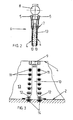
- Fig. 1 is a half section of a blisk drum 1 with blisk blades 2 shown.
- the blisk drum 1 is located in a container 3 filled with water, so that the blisk blades 2 are constantly surrounded by a water bath 13 during surface hardening.
- the device further comprises two parallel and spaced apart, closed at the distal end water jet pipes 4, the opposite open end is connected to a high-pressure water pipe 5 respectively.
- the two - a radiation unit 6 forming - water jet pipes 4 are connected via a holding device 7 fixed to a manipulating device 8, which movement of the irradiation unit 6 in the X-, Y- and Z-direction and their pivotal movement about a vertical and a horizontal axis according to the Arrows A and B allowed.
- nozzle openings 9 for generating a high-speed high-pressure water jet 10 emerging at a high speed are each formed in a row and at a uniform distance.
- the nozzle openings 9 in the two water jet pipes 4 are arranged so that the high-pressure water jets 10 exiting therefrom are directed toward one another precisely in order to exert a force on the blade surface on the pressure side and the suction side of the blisk blade at exactly opposite areas.
- the length of the water jet tubes 4 or of the irradiation unit 6 formed by them corresponds at least to the maximum height of the blisk blades 2 whose surface is to be solidified, so that with one or more movement paths of the irradiation unit the entire blade surface can be detected and uniformly irradiated.
- the respective Bliskschaufel 2 is located in the water bath 13 and between the two water jets 4, which over the high-pressure water lines 5 under high pressure of, for example, 350 bar standing water to produce the directed to the pressure side and the suction side of the Bliskschaufel 2, from the nozzle openings 9 exiting high-pressure water jets 10 is supplied.
- the diameter of the nozzle openings 9 and the high-pressure water jets 10 is according to the present embodiment, 1 mm. Due to the high-speed (v 1 ) enters the stationary water bath 13 (speed v 0 ) in the container 3, moving in the direction of the suction and pressure side of the Bliskschaufel 2 high-pressure water jets 10 are formed - as in Fig.
- the plastic deformation takes place in a single step over the entire blade height very evenly and very gently (without the formation of sharp edges on the edge of the recess and thus without significant increase in surface roughness), so that a subsequent polishing step and associated material removal can be omitted.
- the water jet pipes 4 may also have a rectangular cross-section and have two or more adjacent rows of nozzle openings 9.
Description
- Die Erfindung betrifft ein Verfahren zur Oberflächenverfestigung von Bliskschaufeln und eine Vorrichtung zur Durchführung des Verfahrens.
- Gasturbinenrotoren und insbesondere die Rotoren der Kompressoren von Gasturbinentriebwerken werden unter dem Aspekt der Zuverlässigkeit, Gewichtseinsparung, Leistungssteigerung und Lebensdauer mit einer am Außenumfang einer Rotorscheibe integral ausgebildeten Beschaufelung ausgeführt. Derartige Bauteile werden als Blisks bezeichnet, wobei der Begriff Blisk eine Kurzform des englischsprachigen Ausdrucks "blade integrated disk" ist. Die Herstellung von Blisks erfolgt bekanntermaßen durch Verschweißen, insbesondere Reibschweißen, separat gefertigter Schaufeln mit der Umfangsringfläche der vorzugsweise geschmiedeten Rotorscheibe oder durch einen von der Außenringfläche der Scheibe ausgehenden Materialabtrag mittels spangebender oder elektro-chemischer Verfahren. Nach dem Ausformen und einer Feinbearbeitung der Bliskschaufeln und nach einer Wärmebehandlung der gesamten Blisk bzw. einer aus mehreren miteinander verbundenen Blisks bestehenden Blisktrommel erfolgt durch Krafteinwirkung auf die Oberflächen der Bliskschaufeln eine plastische Verformung und damit eine Erzeugung von Druckeigenspannungen in der Schaufeloberfläche. Aufgrund der dadurch bewirkten Oberflächenverfestigung werden der Widerstand gegen schwingungsinduzierte Rissbildung und Rissausbreitung sowie die Verschleiß- und Korrosionsbeständigkeit und letztlich die Lebensdauer der Blisk bzw. Blisktrommel erhöht. Die Oberflächenbehandlung von Bliskschaufeln erfolgt bekanntermaßen durch eine Kugelstrahlverfestigung, bei der ein sphärisches Strahlmittel mit Hilfe von Druckluft mit hoher Geschwindigkeit gegen die Schaufeloberfläche geschleudert wird. Die hierzu eingesetzten Vorrichtungen sind jedoch insofern nachteilig, als mit dem aus einer Düsenöffnung austretenden Kugelstrahl, der entlang einer Vielzahl von Bahnen über die Schaufelfläche verfahrbar ist und dessen Austrittsgeschwindigkeit und - volumen schwanken kann, eine auf der gesamten Oberfläche gleichmäßige Verfestigung nicht gewährleistet ist. Zudem ist mit der beim Kugelstrahlen auftretenden plastischen Verformung der Schaufeloberfläche eine erhebliche Veränderung der Oberflächentopographie, das heißt, eine Erhöhung der Oberflächenrauheit, verbunden. Die erhöhte Oberflächenrauheit führt zu negativen aerodynamischen Effekten. Zwar kann die Rauheit durch einen zusätzlichen Polierschritt verringert werden, jedoch ist das Polieren aufgrund der komplexen Geometrie der Blisk nur mit erheblichem Aufwand realisierbar. Zudem wird dabei die Wirkung der vorhergehenden Kugelstrahlverfestigung abgeschwächt, da ein Teil der zuvor verfestigten Oberflächenschicht wieder abgetragen wird.
- Die
EP 2 093 021 A1 beschreibt die Kugelstrahlverfestigung von Bliskschaufeln, wobei mittels Druckluft oder Wasser Kugeln durch jeweils eine auf jeder Schaufelseite angeordnete Düse gleichzeitig auf beide Schaufelseiten geschleudert werden. - Die
US 5 778 713 A beschreibt die Strahl-Verfestigung einer Oberfläche eines Werkstücks mittels einer singulären Düse, durch welche ein Wasserstrahl mit sehr hohem Druck und sehr hoher Geschwindigkeit aufgebracht wird. - Der Erfindung liegt die Aufgabe zugrunde, ein Verfahren und eine Vorrichtung zur Oberflächenverfestigung von Bliskschaufeln anzugeben, die eine über die Schaufeloberfläche gleichmäßig verteilte Einbringung von Druckeigenspannungen und somit eine gleichmäßige Verfestigung gewährleistet und eine durch die Verfestigung bedingte Erhöhung der Oberflächenrauheit und die daraus resultierenden nachteiligen Wirkungen vermeidet.
- Erfindungsgemäß wird die Aufgabe mit einem Verfahren gemäß den Merkmalen des Anspruchs 1 und einer gemäß den Merkmalen des Patentanspruchs 2 ausgebildeten Vorrichtung gelöst. Vorteilhafte Weiterbildungen der Erfindung sind Gegenstand der Unteransprüche.
- Der Grundgedanke der Erfindung besteht darin, dass die zu behandelnde Bliskschaufel mindestens im Bearbeitungsbereich oder vollständig in ein Wasserbad eingebracht wird und in das Wasserbad eine Vielzahl von beidseitig und im Wesentlichen senkrecht und jeweils gegenüberliegend auf die beiden Schaufelflächen gerichteten Hochdruck-Wasserstrahlen injiziert werden. Am Umfang der Hochdruck-Wasserstrahlen werden in dem Wasserbad Kavitationsblasen generiert, die nahe der Schaufeloberfläche implodieren und dabei einen Druckimpuls auf die Schaufeloberfläche ausüben, der im Unterschied zu der Kugelschlagwirkung beim Kugelstrahlverfestigen eine plastisch eingeformte Vertiefung mit abgerundetem, das heißt ohne eine scharfe umlaufende Kante ausgebildetem Rand erzeugt. Gegenüber dem Kugelstrahlen wird bei deutlicher verringerter Oberflächenrauheit eine insbesondere auch im filigranen Kantenbereich der Bliskschaufeln schonende Oberflächenverfestigung erreicht. Es entfallen zusätzliche Polierschritte und die Oberflächenfestigkeit wird dahingehend verbessert, dass die verfestigte Oberfläche nicht durch Abtrag negativ in ihren Eigenschaften verändert wird. Zudem ist auch die Bearbeitung kleiner Kehlradien gewährleistet.
- Eine erfindungsgemäße Vorrichtung zur Durchführung des Verfahrens umfasst einen das Wasserbad ausbildenden Behälter zur Aufnahme einer Blisk oder Blisktrommel sowie eine aus im Abstand und parallel angeordneten, an eine Hochdruck-Wasserleitung angeschlossenen Wasserstrahlrohren gebildete Bestrahlungseinheit mit in Längserstreckung der Wasserstrahlrohre und in gleichmäßigem Abstand ausgebildeten Düsenöffnungen zur Erzeugung von das Wasserbad in Richtung der Schaufeloberfläche durchdringenden Hochdruck-Wasserstrahlen. Die Düsenöffnungen der gegenüberliegenden Wasserstrahlrohre sind jeweils aufeinander zu gerichtet und unmittelbar gegenüberliegend angeordnet.
- Der Hochdruck-Wasserstrahl tritt im Wesentlichen senkrecht aus den Düsenöffnungen in Richtung der Schaufelflächen aus. Es ist jedoch eine davon abweichende Austrittsrichtung denkbar. Die Bestrahlungseinheit ist mit einer Manipuliervorrichtung zur Bewegung der Wasserstrahlrohre in beidseitig gleichmäßigem und der Schaufelkrümmung folgendem Abstand von der Schaufeloberfläche verbunden.
- In Ausgestaltung der Erfindung umfasst die Bestrahlungseinheit auf beiden Seiten mindesten ein Wasserstrahlrohr mit jeweils einer Reihe Düsenöffnungen. Die beiderseitigen Wasserstrahlrohre können aber auch einen Rechteckquerschnitt haben und jeweils mindestens eine Reihe Düsenöffnungen aufweisen. Die Länge der Wasserstrahlrohre oder einer Reihe von Düsenöffnungen entspricht einem Teil oder mindestens der gesamten Länge der zu behandelnden Bliskschaufel Die Bestrahlungseinheit ist mit Hilfe der Manipuliervorrichtung in X-, Y- und Z-Richtung linear bewegbar sowie um eine horizontale und eine vertikale Achse schwenkbar.
- Mit der so ausgebildeten Vorrichtung können die Bliskschaufeln vollständig und gleichmäßig sowie mit identischen Bearbeitungsparametern verfestigt werden.
- Ein Ausführungsbeispiel der Erfindung wird anhand der Zeichnung, in der
- Fig. 1
- eine Vorderansicht einer Vorrichtung zur Oberflächenverfestigung einer von Wasser umgebenen Schaufel einer Blisk;
- Fig. 2
- eine Seitenansicht der Vorrichtung nach
Fig. 1 , jedoch ohne den die Blisk aufnehmenden Wasserbehälter; und - Fig. 3
- eine vergrößerte Darstellung eines auf die im Wasser angeordnete Schaufeloberfläche gerichteten Hochdruck-Wasserstrahls
- In
Fig. 1 ist ein Halbschnitt einer Blisktrommel 1 mit Bliskschaufeln 2 dargestellt. Die Blisktrommel 1 befindet sich in einem mit Wasser gefüllten Behälter 3, so dass die Bliskschaufeln 2 während der Oberflächenverfestigung ständig von einem Wasserbad 13 umgeben sind. Die Vorrichtung umfasst des Weiteren zwei parallel und im Abstand zueinander angeordnete, am distalen Ende geschlossene Wasserstrahlrohre 4, deren gegenüberliegendes offenes Ende jeweils an eine Hochdruck-Wasserleitung 5 angeschlossen ist. Die beiden - eine Bestrahlungseinheit 6 bildenden - Wasserstrahlrohre 4 sind über eine Haltevorrichtung 7 fest mit einer Manipuliervorrichtung 8 verbunden, die eine Bewegung der Bestrahlungseinheit 6 in X-, Y- und Z-Richtung sowie deren Schwenkbewegung um eine vertikale und eine horizontale Achse gemäß den Pfeilen A und B erlaubt. An den einander gegenüberliegenden Seiten der Wasserstrahlrohre 4 sind jeweils in einer Reihe und in gleichmäßigem Abstand Düsenöffnungen 9 zur Erzeugung eines mit hoher Geschwindigkeit austretenden Hochdruck-Wasserstrahls 10 ausgebildet. Die Düsenöffnungen 9 in den beiden Wasserstrahlrohren 4 sind so angeordnet, dass die aus diesen austretenden Hochdruck-Wasserstrahlen 10 genau aufeinander zu gerichtet sind, um auf der Druckseite und der Saugseite der Bliskschaufel an genau gegenüberliegenden Bereichen eine Krafteinwirkung auf die Schaufeloberfläche zu bewirken. Die Länge der Wasserstrahlrohre 4 bzw. der von diesen gebildeten Bestrahlungseinheit 6 entspricht mindestens der maximalen Höhe der Bliskschaufeln 2, deren Oberfläche verfestigt werden soll, so dass mit einer oder mehreren Bewegungsbahnen der Bestrahlungseinheit die gesamte Schaufelfläche erfasst und gleichmäßig bestrahlt werden kann. - Während der Verfestigungsbehandlung befindet sich die betreffende Bliskschaufel 2 in dem Wasserbad 13 und zwischen den beiden Wasserstrahlrohren 4, denen über die Hochdruck-Wasserleitungen 5 unter hohem Druck von beispielsweise 350 bar stehendes Wasser zur Erzeugung der auf die Druckseite und die Saugseite der Bliskschaufel 2 gerichteten, aus den Düsenöffnungen 9 austretenden Hochdruck-Wasserstrahlen 10 zugeführt wird. Der Durchmesser der Düsenöffnungen 9 bzw. der Hochdruck-Wasserstrahlen 10 beträgt gemäß dem vorliegenden Ausführungsbeispiel 1 mm. Aufgrund der mit hoher Geschwindigkeit (v1) in das ruhende Wasserbad 13 (Geschwindigkeit v0) im Behälter 3 eintretenden, sich in Richtung der Saug- und Druckseite der Bliskschaufel 2 bewegenden Hochdruck-Wasserstrahlen 10 bilden sich - wie in
Fig. 3 schematisch dargestellt - infolge des dabei unter den Verdampfungsdruck des Wassers sinkenden statischen Drucks Kavitationsblasen 11 (Dampf-oder Gasblasen, Unterdruckblasen) aus, die im Verlauf des Hochdruck-Wasserstrahls 10 mit sich änderndem Druck allmählich zusammenfallen und an oder nahe der Oberfläche der Bliskschaufel 2 implodieren und dabei einen auf die Schaufelfläche wirkenden Mikrostrahl 12 oder Druckimpuls erzeugen. Während der Bearbeitung ist die Bliskschaufel 2 mittig zwischen den beiden Wasserstrahlrohren 4 angeordnet. Die Bestrahlungseinheit 6 wird mit Hilfe der Manipuliervorrichtung 8 mindestens einmal zwischen der Vorderkante und der Hinterkante der Bliskschaufel 2 bewegt und folgt durch Verschwenken der Bestrahlungseinheit 6 mittels der Manipuliervorrichtung 8 dem gekrümmten Verlauf der Schaufelflächen. Während des Verfahrens der Bestrahlungseinheit 6 trifft eine Vielzahl von durch implodierende Kavitationsblasen 11 erzeugten Mikrostrahlen 12 gleichzeitig und gegenüberliegend auf die Druck- und die Saugseite der Bliskschaufel 2 auf, die dort winzige, plastisch eingeformte Vertiefungen 14- jedoch ohne umlaufende scharfe Kanten bzw. mit zur Schaufeloberfläche hin abgerundeten oder unscharfen Kanten - zur Oberflächenverfestigung erzeugen. Die plastische Verformung erfolgt in einem Arbeitsschritt über die gesamte Schaufelhöhe sehr gleichmäßig und dabei sehr schonend (ohne Ausbildung scharfer Kanten am Rand der Vertiefung und somit ohne wesentliche Erhöhung der Oberflächenrauheit), so dass ein nachfolgender Polierschritt und ein damit verbundener Materialabtrag entfallen kann. - Die Erfindung ist nicht auf das zuvor beschriebene Ausführungsbeispiel beschränkt. Beispielsweise können die Wasserstrahlrohre 4 auch einen rechteckigen Querschnitt haben und zwei oder mehr nebeneinander liegende Reihen von Düsenöffnungen 9 aufweisen.
-
- 1
- Blisktrommel
- 2
- Bliskschaufel
- 3
- Behälter
- 4
- Wasserstrahlrohre
- 5
- Hochdruck-Wasserleitung
- 6
- Bestrahlungseinheit
- 7
- Haltevorrichtung
- 8
- Manipuliervorrichtung
- 9
- Düsenöffnung
- 10
- Hochdruck-Wasserstrahl
- 11
- Kavitationsblasen
- 12
- Mikrostrahl (Druckimpuls)
- 13
- Wasserbad
- 14
- plastisch eingeformte Vertiefung
Claims (6)
- Verfahren zur Oberflächenverfestigung von Bliskschaufeln mittels einer Vorrichtung nach Anspruch 2, dadurch gekennzeichnet, dass die zu behandelnde Bliskschaufel vollständig oder mindestens im Bearbeitungsbereich in ein Wasserbad (13) eingebunden wird und in das Wasserbad eine Vielzahl von beidseitig und im Wesentlichen senkrecht und/oder schräg und jeweils gegenüberliegend auf die beiden Schaufelflächen gerichteten Hochdruck-Wasserstrahlen (10) zur Ausbildung von am Umfang der Hochdruck-Wasserstrahlen in dem Wasserbad generierten und nahe der Schaufeloberfläche implodierenden Kavitationsblasen (11) injiziert werden, wobei bei der Implosion erzeugte Mikrostrahlen (12) auf die Schaufeloberflächen wirken und in dieser nicht randscharf plastisch eingeformte Vertiefungen (14) erzeugen.
- Vorrichtung zur Durchführung des Verfahrens zur Oberflächenverfestigung von Bliskschaufeln nach Anspruch 1, mit einem das Wasserbad (13) ausbildenden Behälter (3) zur Aufnahme einer Blisk oder Blisktrommel (1) sowie einer aus im Abstand und parallel angeordneten, an eine HochdruckWasserleitung (5) angeschlossenen Wasserstrahlrohren (4) gebildeten Bestrahlungseinheit (6) mit in Längserstreckung der Wasserstrahlrohre (4) und in gleichmäßigem Abstand ausgebildeten Düsenöffnungen (9) zur Erzeugung von das Wasserbad (13) in Richtung der Schaufeloberfläche durchdringenden Hochdruck-Wasserstrahlen (10), wobei die Düsenöffnungen (9) der gegenüberliegenden Wasserstrahlrohre (4) jeweils aufeinander zu gerichtet und unmittelbar gegenüberliegend angeordnet sind und die Bestrahlungseinheit (6) mit einer Manipuliervorrichtung (8) zur Bewegung der Wasserstrahlrohre (4) in beidseitig gleichmäßigem Abstand von der Schaufeloberfläche verbunden ist.
- Vorrichtung nach Anspruch 2, dadurch gekennzeichnet, dass die Bestrahlungseinheit (6) auf beiden Seiten mindestens ein Wasserstrahlrohr (4) mit jeweils einer Reihe Düsenöffnungen (9) umfasst.
- Vorrichtung nach Anspruch 2, dadurch gekennzeichnet, dass die beiderseitigen Wasserstrahlrohre (4) einen Rechteckquerschnitt haben und jeweils mindestens eine Reihe Düsenöffnungen (9) aufweisen.
- Vorrichtung nach Anspruch 2, dadurch gekennzeichnet, dass die Länge der Wasserstrahlrohre (4) oder einer Reihe von Düsenöffnungen (9) einen Tell oder mindestens die ganze Länge der zu behandelnden Bliskschaufel (2) erfasst.
- Vorrichtung nach Anspruch 2, dadurch gekennzeichnet, dass die Bestrahlungseinheit (6) mit Hilfe der Manipuliervorrichtung (8) in X-, Y- und Z-Richtung linear bewegbar sowie um eine horizontale und eine vertikale Achse (A, B) schwenkbar ist.
Applications Claiming Priority (1)
| Application Number | Priority Date | Filing Date | Title |
|---|---|---|---|
| DE102010001287A DE102010001287A1 (de) | 2010-01-27 | 2010-01-27 | Verfahren und Vorrichtung zur Oberflächenverfestigung von Bliskschaufeln |
Publications (2)
| Publication Number | Publication Date |
|---|---|
| EP2353772A1 EP2353772A1 (de) | 2011-08-10 |
| EP2353772B1 true EP2353772B1 (de) | 2013-03-06 |
Family
ID=43838189
Family Applications (1)
| Application Number | Title | Priority Date | Filing Date |
|---|---|---|---|
| EP10008431A Not-in-force EP2353772B1 (de) | 2010-01-27 | 2010-08-12 | Verfahren und Vorrichtung zur Oberflächenverfestigung von Bliskschaufeln |
Country Status (4)
| Country | Link |
|---|---|
| US (1) | US8739589B2 (de) |
| EP (1) | EP2353772B1 (de) |
| JP (1) | JP4970587B2 (de) |
| DE (1) | DE102010001287A1 (de) |
Families Citing this family (12)
| Publication number | Priority date | Publication date | Assignee | Title |
|---|---|---|---|---|
| DE102011007224A1 (de) * | 2011-04-12 | 2012-10-18 | Rolls-Royce Deutschland Ltd & Co Kg | Verfahren und Herstellung eines einstückigen Rotorbereiches und einstückiger Rotorbereich |
| DE102012018605A1 (de) | 2012-09-20 | 2014-03-20 | Rolls-Royce Deutschland Ltd & Co Kg | Walzwerkzeugvorrichtung |
| DE102012018604A1 (de) | 2012-09-20 | 2014-03-20 | Rolls-Royce Deutschland Ltd & Co Kg | Walzwerkzeugvorrichtung |
| US10406583B2 (en) | 2015-12-10 | 2019-09-10 | The Boeing Company | Apparatus, system, and method for forming metal parts |
| JP6872929B2 (ja) | 2017-02-23 | 2021-05-19 | 株式会社スギノマシン | ウォータージェットピーニング方法 |
| DE202017102179U1 (de) * | 2017-04-11 | 2018-04-13 | Piller Entgrattechnik Gmbh | Vorrichtung zum Aufrauen von Zylinderlaufflächen |
| DE102018110632A1 (de) * | 2018-05-03 | 2019-11-07 | Rolls-Royce Deutschland Ltd & Co Kg | Verfahren zur Herstellung eines Bauteils |
| US11298799B2 (en) | 2018-05-03 | 2022-04-12 | General Electric Company | Dual sided shot peening of BLISK airfoils |
| CN111763809B (zh) * | 2020-06-10 | 2021-10-15 | 中国航发北京航空材料研究院 | 一种空心叶片内腔禁喷区的保护装置及装配方法 |
| CN111944972B (zh) * | 2020-07-31 | 2022-02-11 | 中国航发北京航空材料研究院 | 一种空心叶片的喷丸方法 |
| CN115056147B (zh) * | 2022-06-21 | 2023-11-14 | 华东理工大学 | 回转工件水射流表面强化抛光装置及其加工方法 |
| CN115179178B (zh) * | 2022-07-05 | 2023-11-14 | 华东理工大学 | 叶盘叶片水射流强化与抛光一体化系统与方法 |
Family Cites Families (60)
| Publication number | Priority date | Publication date | Assignee | Title |
|---|---|---|---|---|
| US2117648A (en) | 1935-11-22 | 1938-05-17 | Pangborn Corp | Method of and apparatus for cleaning tubular bodies |
| US2439032A (en) | 1945-11-01 | 1948-04-06 | Gen Motors Corp | Shot blasting nozzle |
| GB615462A (en) | 1946-03-26 | 1949-01-06 | Brush Electrical Eng | Improvements in nozzles for abrasive blasting |
| US3482423A (en) * | 1968-02-26 | 1969-12-09 | Metal Improvement Co | Blade peening masking apparatus |
| US4329862A (en) | 1980-01-21 | 1982-05-18 | The Boeing Company | Shot peen forming of compound contours |
| US4454740A (en) | 1981-09-10 | 1984-06-19 | United Technologies Corporation | Method for simultaneous peening and smoothing |
| US4426867A (en) | 1981-09-10 | 1984-01-24 | United Technologies Corporation | Method of peening airfoils and thin edged workpieces |
| US4616496A (en) | 1985-05-07 | 1986-10-14 | Westinghouse Electric Corp. | Rotopeening apparatus having a flexible spindle |
| US5125425A (en) | 1991-02-27 | 1992-06-30 | Folts Michael E | Cleaning and deburring nozzle |
| US5107631A (en) | 1991-05-23 | 1992-04-28 | Engineered Abrasives, Inc. | Abrasive blasting apparatus |
| US5596912A (en) | 1993-08-12 | 1997-01-28 | Formica Technology, Inc. | Press plate having textured surface formed by simultaneous shot peening |
| US5476363A (en) | 1993-10-15 | 1995-12-19 | Charles E. Sohl | Method and apparatus for reducing stress on the tips of turbine or compressor blades |
| US5664992A (en) | 1994-06-20 | 1997-09-09 | Abclean America, Inc. | Apparatus and method for cleaning tubular members |
| US5790620A (en) * | 1995-01-31 | 1998-08-04 | Kabushiki Kaisha Toshiba | Underwater laser processing method and apparatus |
| US6551064B1 (en) | 1996-07-24 | 2003-04-22 | General Electric Company | Laser shock peened gas turbine engine intermetallic parts |
| US5988188A (en) | 1996-12-31 | 1999-11-23 | Jir, Inc. | Method and apparatus to remove obstructions from sewers without cutters or chemicals |
| US5778713A (en) * | 1997-05-13 | 1998-07-14 | Waterjet Technology, Inc. | Method and apparatus for ultra high pressure water jet peening |
| US6037004A (en) | 1997-12-19 | 2000-03-14 | United Technologies Corporation | Shield and method for protecting an airfoil surface |
| US5998755A (en) | 1997-12-19 | 1999-12-07 | United Technologies Corporation | Tooling assembly for positioning airfoils of a rotary machine |
| JP2000087897A (ja) * | 1998-09-08 | 2000-03-28 | Hitachi Ltd | ガスタービンの圧縮機翼およびガスタービン |
| US5948293A (en) | 1998-12-03 | 1999-09-07 | General Electric Company | Laser shock peening quality assurance by volumetric analysis of laser shock peened dimple |
| JP2000263337A (ja) | 1999-01-13 | 2000-09-26 | Japan Science & Technology Corp | 金属部品等の表面改質および洗浄方法およびその装置 |
| JP4240972B2 (ja) * | 1999-01-13 | 2009-03-18 | 独立行政法人科学技術振興機構 | 金属部品等の表面改質および洗浄方法およびその装置 |
| JP3803734B2 (ja) * | 1999-01-26 | 2006-08-02 | 株式会社日立製作所 | ウオータージェットピーニング装置 |
| US6296448B1 (en) | 1999-09-30 | 2001-10-02 | General Electric Company | Simultaneous offset dual sided laser shock peening |
| DE10037029A1 (de) | 2000-07-27 | 2002-02-28 | Kugelstrahlzentrum Aachen Gmbh | Verfahren und Vorrichtung zum Umformen von Strukturbauteilen |
| CA2317845C (en) | 2000-09-08 | 2006-12-19 | Steven Kennerknecht | Shaped metal panels and forming same by shot peening |
| US7028378B2 (en) | 2000-10-12 | 2006-04-18 | Sonats-Societe Des Nouvelles Applications Des Techniques De Surfaces | Method of shot blasting and a machine for implementing such a method |
| FR2816636B1 (fr) | 2000-11-16 | 2003-07-18 | Snecma Moteurs | Grenaillage des sommets des aubes refroidies |
| US6541733B1 (en) | 2001-01-29 | 2003-04-01 | General Electric Company | Laser shock peening integrally bladed rotor blade edges |
| JP2002326161A (ja) | 2001-04-26 | 2002-11-12 | Sintokogio Ltd | ショットピーニング方法およびその装置 |
| JP2002346847A (ja) * | 2001-05-24 | 2002-12-04 | Babcock Hitachi Kk | ウォータージェット・レーザ併用ピーニング方法及び装置 |
| JP4655420B2 (ja) * | 2001-07-02 | 2011-03-23 | Jfeスチール株式会社 | プレス成形性に優れた溶融亜鉛めっき鋼帯の製造方法 |
| US6664506B2 (en) | 2001-08-01 | 2003-12-16 | Lsp Technologies, Inc. | Method using laser shock processing to provide improved residual stress profile characteristics |
| US6875953B2 (en) | 2002-07-29 | 2005-04-05 | Lsp Technologies, Inc. | Method using laser shock processing to provide improved residual stress profile characteristics |
| US7159425B2 (en) | 2003-03-14 | 2007-01-09 | Prevey Paul S | Method and apparatus for providing a layer of compressive residual stress in the surface of a part |
| US6993948B2 (en) * | 2003-06-13 | 2006-02-07 | General Electric Company | Methods for altering residual stresses using mechanically induced liquid cavitation |
| US6969821B2 (en) | 2003-06-30 | 2005-11-29 | General Electric Company | Airfoil qualification system and method |
| DE102004001394A1 (de) | 2004-01-09 | 2005-08-04 | Mtu Aero Engines Gmbh | Verfahren zur Herstellung bzw. Bearbeitung von Bauteilen |
| US20060021410A1 (en) | 2004-07-30 | 2006-02-02 | Sonats-Societe Des Nouvelles Applications Des Techniques De Surfaces | Shot, devices, and installations for ultrasonic peening, and parts treated thereby |
| DE102004037954A1 (de) | 2004-08-05 | 2006-03-16 | Mtu Aero Engines Gmbh | Vorrichtung zum Oberflächenstrahlen von Bauteilen |
| JP2006058145A (ja) * | 2004-08-20 | 2006-03-02 | Toshiba Corp | ウォータージェットピーニング施工装置、ホーンノズル及びその施工方法 |
| DE102004042878A1 (de) * | 2004-09-04 | 2006-03-09 | Mtu Aero Engines Gmbh | Verfahren zur Reparatur von Turbomaschinenschaufeln |
| US7125322B1 (en) | 2004-09-17 | 2006-10-24 | Electronics, Inc. | Media transport device providing stable flow of media |
| EP1645363A1 (de) * | 2004-10-05 | 2006-04-12 | Siemens Aktiengesellschaft | Verfahren und Vorrichtung zum Glätten der Oberfläche eines Bauteils |
| JP4336290B2 (ja) * | 2004-10-29 | 2009-09-30 | ツネイシホールディングス株式会社 | 液滴噴射ノズル |
| US7140216B2 (en) | 2004-11-18 | 2006-11-28 | General Electric Company | laser aligned shotpeen nozzle |
| ITMI20050064A1 (it) | 2005-01-20 | 2006-07-21 | Nuovo Pignone Spa | Metodo di lavorazione di un semilavorato per l'ottenimento di una girante dotata di una pluralita' di pale realizzate di pezzo con la stessa |
| JP4448789B2 (ja) * | 2005-04-25 | 2010-04-14 | 日立Geニュークリア・エナジー株式会社 | 材料表面の処理方法及びその装置 |
| US7217102B2 (en) | 2005-06-30 | 2007-05-15 | General Electric Campany | Countering laser shock peening induced airfoil twist using shot peening |
| FR2889669B1 (fr) | 2005-08-12 | 2007-11-02 | Snecma | Piece metallique traitee par mise en compression de sous couches. procede pour obtenir une telle piece. |
| WO2007055864A2 (en) | 2005-10-12 | 2007-05-18 | Surface Technology Holdings, Ltd | Improved integrally bladed rotating turbo machinery and method and apparatus for achieving the same |
| US9097496B2 (en) * | 2006-04-20 | 2015-08-04 | Sikorsky Aircraft Corporation | Lightweight projectile resistant armor system with surface enhancement |
| DE502007001920D1 (de) | 2006-05-26 | 2009-12-17 | Siemens Ag | Strahlvorrichtung |
| DE102006058675A1 (de) | 2006-12-13 | 2008-06-19 | Mtu Aero Engines Gmbh | Vorrichtung und Verfahren zum Oberflächenstrahlen eines Bauteils einer Gasturbine |
| DE102006058678A1 (de) | 2006-12-13 | 2008-07-03 | Mtu Aero Engines Gmbh | Verfahren und Vorrichtung zum Oberflächenstrahlen eines Teilelements eines Bauteils einer Gasturbine |
| US7716961B2 (en) * | 2007-08-29 | 2010-05-18 | Hitachi-Ge Nuclear Energy, Ltd. | Method for executing water jet peening |
| DE102008010847A1 (de) * | 2008-02-25 | 2009-08-27 | Rolls-Royce Deutschland Ltd & Co Kg | Verfahren und Vorrichtung zum Kugelstrahlverfestigen von Bliskschaufeln |
| DE102008014726A1 (de) * | 2008-03-18 | 2009-09-24 | Rolls-Royce Deutschland Ltd & Co Kg | Verfahren zur Kugelstrahlbehandlung von integral beschaufelten Rotoren |
| DE102009021582A1 (de) | 2009-05-15 | 2010-12-02 | Rolls-Royce Deutschland Ltd & Co Kg | Verfahren zur Oberflächenverfestigung und -glättung von metallischen Bauteilen |
-
2010
- 2010-01-27 DE DE102010001287A patent/DE102010001287A1/de not_active Withdrawn
- 2010-08-12 EP EP10008431A patent/EP2353772B1/de not_active Not-in-force
- 2010-12-02 JP JP2010269250A patent/JP4970587B2/ja active Active
-
2011
- 2011-01-14 US US13/007,143 patent/US8739589B2/en not_active Expired - Fee Related
Also Published As
| Publication number | Publication date |
|---|---|
| US20110179844A1 (en) | 2011-07-28 |
| JP4970587B2 (ja) | 2012-07-11 |
| US8739589B2 (en) | 2014-06-03 |
| JP2011153619A (ja) | 2011-08-11 |
| EP2353772A1 (de) | 2011-08-10 |
| DE102010001287A1 (de) | 2011-07-28 |
Similar Documents
| Publication | Publication Date | Title |
|---|---|---|
| EP2353772B1 (de) | Verfahren und Vorrichtung zur Oberflächenverfestigung von Bliskschaufeln | |
| EP2093021B1 (de) | Verfahren und Vorrichtung zum Kugelstrahlverfestigen von Bliskschaufeln | |
| EP1914323B1 (de) | Verfahren zum Einbringen von Druckeigenspannungen mittels Kugelstrahlen | |
| EP2723508B1 (de) | Vorrichtung zum behandeln von werkstücken | |
| EP1508395B1 (de) | Vorrichtung zum Elysiersenken | |
| DE102008014726A1 (de) | Verfahren zur Kugelstrahlbehandlung von integral beschaufelten Rotoren | |
| EP3914418B1 (de) | Prozess zur strahlbearbeitung eines platten- oder rohrförmigen werkstücks | |
| EP1986817B1 (de) | Strahlkammer zum oberflächenstrahlen, insbesondere zum ultraschall kugelstrahlen von gasturbinen-bauteilen | |
| DE102012109533B4 (de) | Vorrichtung zum Entgraten, Entspanen und Reinigen eines schlanken Bauteils, wie Bohrer, Fräser und dgl. | |
| EP1761361B1 (de) | Verfahren und vorrichtung zum oberflächenstrahlen von gasturbinenschaufeln im bereich ihrer schaufelfüsse | |
| EP2072176A1 (de) | Verfahren zur Herstellung einer Erosionsschutzschicht aus Stahl durch Laserauftragschweissen; Bauteil mit einer solchen Erosionsschutzschicht | |
| DE102014012480A1 (de) | Beschaufelung einer Strömungsmaschine, Herstellverfahren und Laufrad einer Strömungsmaschine | |
| EP2251140A1 (de) | Verfahren zur Oberflächenverfestigung und -glättung von metallischen Bauteilen | |
| DE4341869A1 (de) | Entfernung von harten Überzügen mit Ultrahochdruck-Flachstrahlen | |
| EP2885441B1 (de) | Verfahren zum beschichten durch thermisches spritzen mit geneigtem partikelstrahl | |
| ITMI932587A1 (it) | Ugello con getto a ventaglio a pressione ultra elevata. | |
| EP2099585B1 (de) | Vorrichtung und verfahren zum oberflächenstrahlen eines bauteils einer gasturbine | |
| DE10319020B4 (de) | Verfahren zum Verrunden von Kanten an Schaufeln von Turbomaschinen | |
| DE102009025621B4 (de) | Verfahren zum Herstellen eines metallischen Bauteils mit einer gehärteten Oberflächenschicht sowie danach hergestelltes Bauteil | |
| EP2164679B1 (de) | Verfahren und vorrichtung zum oberflächenstrahlen eines bauteils im bereich einer durchgangsöffnung | |
| DE102019201656A1 (de) | Verfahren zum glätten einer oberfläche eines bauteils | |
| DE102005054866A1 (de) | Verfahren zum Herstellen von metallischen Bauteilen, insbesondere für Turbomaschinen, mit kleinen Kantenradien | |
| WO2012059373A1 (de) | Verfahren, strahlmittel und vorrichtung zum behandeln eines bauelements | |
| DE10118723B4 (de) | Verfahren zur Oberflächenbearbeitung eines Werkstückes und Vorrichtung zur Durchführung des Verfahrens | |
| EP3530408A1 (de) | Vorrichtung zum hochdruckfluidstrahlschneiden |
Legal Events
| Date | Code | Title | Description |
|---|---|---|---|
| PUAI | Public reference made under article 153(3) epc to a published international application that has entered the european phase |
Free format text: ORIGINAL CODE: 0009012 |
|
| AK | Designated contracting states |
Kind code of ref document: A1 Designated state(s): AL AT BE BG CH CY CZ DE DK EE ES FI FR GB GR HR HU IE IS IT LI LT LU LV MC MK MT NL NO PL PT RO SE SI SK SM TR |
|
| AX | Request for extension of the european patent |
Extension state: BA ME RS |
|
| 17P | Request for examination filed |
Effective date: 20111205 |
|
| GRAP | Despatch of communication of intention to grant a patent |
Free format text: ORIGINAL CODE: EPIDOSNIGR1 |
|
| RIN1 | Information on inventor provided before grant (corrected) |
Inventor name: HENNIG, WOLFGANG Inventor name: FELDMANN, GOETZ G., DR. |
|
| GRAS | Grant fee paid |
Free format text: ORIGINAL CODE: EPIDOSNIGR3 |
|
| GRAA | (expected) grant |
Free format text: ORIGINAL CODE: 0009210 |
|
| AK | Designated contracting states |
Kind code of ref document: B1 Designated state(s): AL AT BE BG CH CY CZ DE DK EE ES FI FR GB GR HR HU IE IS IT LI LT LU LV MC MK MT NL NO PL PT RO SE SI SK SM TR |
|
| REG | Reference to a national code |
Ref country code: GB Ref legal event code: FG4D Free format text: NOT ENGLISH |
|
| REG | Reference to a national code |
Ref country code: AT Ref legal event code: REF Ref document number: 599316 Country of ref document: AT Kind code of ref document: T Effective date: 20130315 Ref country code: CH Ref legal event code: EP |
|
| REG | Reference to a national code |
Ref country code: IE Ref legal event code: FG4D Free format text: LANGUAGE OF EP DOCUMENT: GERMAN |
|
| REG | Reference to a national code |
Ref country code: DE Ref legal event code: R096 Ref document number: 502010002385 Country of ref document: DE Effective date: 20130502 |
|
| PG25 | Lapsed in a contracting state [announced via postgrant information from national office to epo] |
Ref country code: NO Free format text: LAPSE BECAUSE OF FAILURE TO SUBMIT A TRANSLATION OF THE DESCRIPTION OR TO PAY THE FEE WITHIN THE PRESCRIBED TIME-LIMIT Effective date: 20130606 Ref country code: SE Free format text: LAPSE BECAUSE OF FAILURE TO SUBMIT A TRANSLATION OF THE DESCRIPTION OR TO PAY THE FEE WITHIN THE PRESCRIBED TIME-LIMIT Effective date: 20130306 Ref country code: LT Free format text: LAPSE BECAUSE OF FAILURE TO SUBMIT A TRANSLATION OF THE DESCRIPTION OR TO PAY THE FEE WITHIN THE PRESCRIBED TIME-LIMIT Effective date: 20130306 Ref country code: ES Free format text: LAPSE BECAUSE OF FAILURE TO SUBMIT A TRANSLATION OF THE DESCRIPTION OR TO PAY THE FEE WITHIN THE PRESCRIBED TIME-LIMIT Effective date: 20130617 Ref country code: BG Free format text: LAPSE BECAUSE OF FAILURE TO SUBMIT A TRANSLATION OF THE DESCRIPTION OR TO PAY THE FEE WITHIN THE PRESCRIBED TIME-LIMIT Effective date: 20130606 |
|
| REG | Reference to a national code |
Ref country code: NL Ref legal event code: VDEP Effective date: 20130306 |
|
| REG | Reference to a national code |
Ref country code: LT Ref legal event code: MG4D |
|
| PG25 | Lapsed in a contracting state [announced via postgrant information from national office to epo] |
Ref country code: SI Free format text: LAPSE BECAUSE OF FAILURE TO SUBMIT A TRANSLATION OF THE DESCRIPTION OR TO PAY THE FEE WITHIN THE PRESCRIBED TIME-LIMIT Effective date: 20130306 Ref country code: GR Free format text: LAPSE BECAUSE OF FAILURE TO SUBMIT A TRANSLATION OF THE DESCRIPTION OR TO PAY THE FEE WITHIN THE PRESCRIBED TIME-LIMIT Effective date: 20130607 Ref country code: FI Free format text: LAPSE BECAUSE OF FAILURE TO SUBMIT A TRANSLATION OF THE DESCRIPTION OR TO PAY THE FEE WITHIN THE PRESCRIBED TIME-LIMIT Effective date: 20130306 Ref country code: LV Free format text: LAPSE BECAUSE OF FAILURE TO SUBMIT A TRANSLATION OF THE DESCRIPTION OR TO PAY THE FEE WITHIN THE PRESCRIBED TIME-LIMIT Effective date: 20130306 |
|
| PG25 | Lapsed in a contracting state [announced via postgrant information from national office to epo] |
Ref country code: HR Free format text: LAPSE BECAUSE OF FAILURE TO SUBMIT A TRANSLATION OF THE DESCRIPTION OR TO PAY THE FEE WITHIN THE PRESCRIBED TIME-LIMIT Effective date: 20130306 |
|
| PG25 | Lapsed in a contracting state [announced via postgrant information from national office to epo] |
Ref country code: NL Free format text: LAPSE BECAUSE OF FAILURE TO SUBMIT A TRANSLATION OF THE DESCRIPTION OR TO PAY THE FEE WITHIN THE PRESCRIBED TIME-LIMIT Effective date: 20130306 Ref country code: CZ Free format text: LAPSE BECAUSE OF FAILURE TO SUBMIT A TRANSLATION OF THE DESCRIPTION OR TO PAY THE FEE WITHIN THE PRESCRIBED TIME-LIMIT Effective date: 20130306 Ref country code: PT Free format text: LAPSE BECAUSE OF FAILURE TO SUBMIT A TRANSLATION OF THE DESCRIPTION OR TO PAY THE FEE WITHIN THE PRESCRIBED TIME-LIMIT Effective date: 20130708 Ref country code: RO Free format text: LAPSE BECAUSE OF FAILURE TO SUBMIT A TRANSLATION OF THE DESCRIPTION OR TO PAY THE FEE WITHIN THE PRESCRIBED TIME-LIMIT Effective date: 20130306 Ref country code: EE Free format text: LAPSE BECAUSE OF FAILURE TO SUBMIT A TRANSLATION OF THE DESCRIPTION OR TO PAY THE FEE WITHIN THE PRESCRIBED TIME-LIMIT Effective date: 20130306 Ref country code: IS Free format text: LAPSE BECAUSE OF FAILURE TO SUBMIT A TRANSLATION OF THE DESCRIPTION OR TO PAY THE FEE WITHIN THE PRESCRIBED TIME-LIMIT Effective date: 20130706 Ref country code: SK Free format text: LAPSE BECAUSE OF FAILURE TO SUBMIT A TRANSLATION OF THE DESCRIPTION OR TO PAY THE FEE WITHIN THE PRESCRIBED TIME-LIMIT Effective date: 20130306 |
|
| PG25 | Lapsed in a contracting state [announced via postgrant information from national office to epo] |
Ref country code: PL Free format text: LAPSE BECAUSE OF FAILURE TO SUBMIT A TRANSLATION OF THE DESCRIPTION OR TO PAY THE FEE WITHIN THE PRESCRIBED TIME-LIMIT Effective date: 20130306 |
|
| PLBE | No opposition filed within time limit |
Free format text: ORIGINAL CODE: 0009261 |
|
| STAA | Information on the status of an ep patent application or granted ep patent |
Free format text: STATUS: NO OPPOSITION FILED WITHIN TIME LIMIT |
|
| PG25 | Lapsed in a contracting state [announced via postgrant information from national office to epo] |
Ref country code: DK Free format text: LAPSE BECAUSE OF FAILURE TO SUBMIT A TRANSLATION OF THE DESCRIPTION OR TO PAY THE FEE WITHIN THE PRESCRIBED TIME-LIMIT Effective date: 20130306 |
|
| 26N | No opposition filed |
Effective date: 20131209 |
|
| BERE | Be: lapsed |
Owner name: ROLLS-ROYCE DEUTSCHLAND LTD & CO K.G. Effective date: 20130831 |
|
| PG25 | Lapsed in a contracting state [announced via postgrant information from national office to epo] |
Ref country code: IT Free format text: LAPSE BECAUSE OF FAILURE TO SUBMIT A TRANSLATION OF THE DESCRIPTION OR TO PAY THE FEE WITHIN THE PRESCRIBED TIME-LIMIT Effective date: 20130306 |
|
| REG | Reference to a national code |
Ref country code: DE Ref legal event code: R097 Ref document number: 502010002385 Country of ref document: DE Effective date: 20131209 |
|
| PG25 | Lapsed in a contracting state [announced via postgrant information from national office to epo] |
Ref country code: MC Free format text: LAPSE BECAUSE OF FAILURE TO SUBMIT A TRANSLATION OF THE DESCRIPTION OR TO PAY THE FEE WITHIN THE PRESCRIBED TIME-LIMIT Effective date: 20130306 |
|
| REG | Reference to a national code |
Ref country code: IE Ref legal event code: MM4A |
|
| PG25 | Lapsed in a contracting state [announced via postgrant information from national office to epo] |
Ref country code: BE Free format text: LAPSE BECAUSE OF NON-PAYMENT OF DUE FEES Effective date: 20130831 |
|
| PG25 | Lapsed in a contracting state [announced via postgrant information from national office to epo] |
Ref country code: IE Free format text: LAPSE BECAUSE OF NON-PAYMENT OF DUE FEES Effective date: 20130812 |
|
| REG | Reference to a national code |
Ref country code: CH Ref legal event code: PL |
|
| PG25 | Lapsed in a contracting state [announced via postgrant information from national office to epo] |
Ref country code: LI Free format text: LAPSE BECAUSE OF NON-PAYMENT OF DUE FEES Effective date: 20140831 Ref country code: CH Free format text: LAPSE BECAUSE OF NON-PAYMENT OF DUE FEES Effective date: 20140831 |
|
| PG25 | Lapsed in a contracting state [announced via postgrant information from national office to epo] |
Ref country code: SM Free format text: LAPSE BECAUSE OF FAILURE TO SUBMIT A TRANSLATION OF THE DESCRIPTION OR TO PAY THE FEE WITHIN THE PRESCRIBED TIME-LIMIT Effective date: 20130306 |
|
| PG25 | Lapsed in a contracting state [announced via postgrant information from national office to epo] |
Ref country code: CY Free format text: LAPSE BECAUSE OF FAILURE TO SUBMIT A TRANSLATION OF THE DESCRIPTION OR TO PAY THE FEE WITHIN THE PRESCRIBED TIME-LIMIT Effective date: 20130306 Ref country code: MT Free format text: LAPSE BECAUSE OF FAILURE TO SUBMIT A TRANSLATION OF THE DESCRIPTION OR TO PAY THE FEE WITHIN THE PRESCRIBED TIME-LIMIT Effective date: 20130306 Ref country code: TR Free format text: LAPSE BECAUSE OF FAILURE TO SUBMIT A TRANSLATION OF THE DESCRIPTION OR TO PAY THE FEE WITHIN THE PRESCRIBED TIME-LIMIT Effective date: 20130306 |
|
| PG25 | Lapsed in a contracting state [announced via postgrant information from national office to epo] |
Ref country code: HU Free format text: LAPSE BECAUSE OF FAILURE TO SUBMIT A TRANSLATION OF THE DESCRIPTION OR TO PAY THE FEE WITHIN THE PRESCRIBED TIME-LIMIT; INVALID AB INITIO Effective date: 20100812 Ref country code: LU Free format text: LAPSE BECAUSE OF NON-PAYMENT OF DUE FEES Effective date: 20130812 Ref country code: MK Free format text: LAPSE BECAUSE OF FAILURE TO SUBMIT A TRANSLATION OF THE DESCRIPTION OR TO PAY THE FEE WITHIN THE PRESCRIBED TIME-LIMIT Effective date: 20130306 |
|
| REG | Reference to a national code |
Ref country code: FR Ref legal event code: PLFP Year of fee payment: 7 |
|
| REG | Reference to a national code |
Ref country code: AT Ref legal event code: MM01 Ref document number: 599316 Country of ref document: AT Kind code of ref document: T Effective date: 20150812 |
|
| PG25 | Lapsed in a contracting state [announced via postgrant information from national office to epo] |
Ref country code: AT Free format text: LAPSE BECAUSE OF NON-PAYMENT OF DUE FEES Effective date: 20150812 |
|
| REG | Reference to a national code |
Ref country code: FR Ref legal event code: PLFP Year of fee payment: 8 |
|
| REG | Reference to a national code |
Ref country code: FR Ref legal event code: PLFP Year of fee payment: 9 |
|
| PG25 | Lapsed in a contracting state [announced via postgrant information from national office to epo] |
Ref country code: AL Free format text: LAPSE BECAUSE OF FAILURE TO SUBMIT A TRANSLATION OF THE DESCRIPTION OR TO PAY THE FEE WITHIN THE PRESCRIBED TIME-LIMIT Effective date: 20130306 |
|
| PGFP | Annual fee paid to national office [announced via postgrant information from national office to epo] |
Ref country code: FR Payment date: 20190826 Year of fee payment: 10 Ref country code: DE Payment date: 20190828 Year of fee payment: 10 |
|
| PGFP | Annual fee paid to national office [announced via postgrant information from national office to epo] |
Ref country code: GB Payment date: 20190827 Year of fee payment: 10 |
|
| REG | Reference to a national code |
Ref country code: DE Ref legal event code: R082 Ref document number: 502010002385 Country of ref document: DE |
|
| REG | Reference to a national code |
Ref country code: DE Ref legal event code: R119 Ref document number: 502010002385 Country of ref document: DE |
|
| GBPC | Gb: european patent ceased through non-payment of renewal fee |
Effective date: 20200812 |
|
| PG25 | Lapsed in a contracting state [announced via postgrant information from national office to epo] |
Ref country code: DE Free format text: LAPSE BECAUSE OF NON-PAYMENT OF DUE FEES Effective date: 20210302 Ref country code: FR Free format text: LAPSE BECAUSE OF NON-PAYMENT OF DUE FEES Effective date: 20200831 |
|
| PG25 | Lapsed in a contracting state [announced via postgrant information from national office to epo] |
Ref country code: GB Free format text: LAPSE BECAUSE OF NON-PAYMENT OF DUE FEES Effective date: 20200812 |