EP3733043B1 - Dispositif endoscopique - Google Patents
Dispositif endoscopique Download PDFInfo
- Publication number
- EP3733043B1 EP3733043B1 EP20171798.0A EP20171798A EP3733043B1 EP 3733043 B1 EP3733043 B1 EP 3733043B1 EP 20171798 A EP20171798 A EP 20171798A EP 3733043 B1 EP3733043 B1 EP 3733043B1
- Authority
- EP
- European Patent Office
- Prior art keywords
- base body
- fin
- endoscopic device
- main extension
- section
- Prior art date
- Legal status (The legal status is an assumption and is not a legal conclusion. Google has not performed a legal analysis and makes no representation as to the accuracy of the status listed.)
- Active
Links
- 239000000463 material Substances 0.000 claims description 12
- 229920002725 thermoplastic elastomer Polymers 0.000 claims description 7
- 230000007423 decrease Effects 0.000 claims description 6
- 230000001012 protector Effects 0.000 claims description 5
- 238000000034 method Methods 0.000 description 43
- 238000004519 manufacturing process Methods 0.000 description 7
- 239000004033 plastic Substances 0.000 description 5
- 239000013013 elastic material Substances 0.000 description 4
- 238000001746 injection moulding Methods 0.000 description 3
- 210000003437 trachea Anatomy 0.000 description 2
- 238000009423 ventilation Methods 0.000 description 2
- 239000000853 adhesive Substances 0.000 description 1
- 230000001070 adhesive effect Effects 0.000 description 1
- 230000009286 beneficial effect Effects 0.000 description 1
- 238000005266 casting Methods 0.000 description 1
- 230000003247 decreasing effect Effects 0.000 description 1
- 230000001419 dependent effect Effects 0.000 description 1
- 238000011161 development Methods 0.000 description 1
- 230000018109 developmental process Effects 0.000 description 1
- 230000000694 effects Effects 0.000 description 1
- 238000003780 insertion Methods 0.000 description 1
- 230000037431 insertion Effects 0.000 description 1
- 230000003068 static effect Effects 0.000 description 1
- 230000007704 transition Effects 0.000 description 1
- 238000009827 uniform distribution Methods 0.000 description 1
- 238000003466 welding Methods 0.000 description 1
Images


Classifications
-
- A—HUMAN NECESSITIES
- A61—MEDICAL OR VETERINARY SCIENCE; HYGIENE
- A61B—DIAGNOSIS; SURGERY; IDENTIFICATION
- A61B1/00—Instruments for performing medical examinations of the interior of cavities or tubes of the body by visual or photographical inspection, e.g. endoscopes; Illuminating arrangements therefor
- A61B1/00064—Constructional details of the endoscope body
- A61B1/00105—Constructional details of the endoscope body characterised by modular construction
-
- A—HUMAN NECESSITIES
- A61—MEDICAL OR VETERINARY SCIENCE; HYGIENE
- A61B—DIAGNOSIS; SURGERY; IDENTIFICATION
- A61B1/00—Instruments for performing medical examinations of the interior of cavities or tubes of the body by visual or photographical inspection, e.g. endoscopes; Illuminating arrangements therefor
- A61B1/00064—Constructional details of the endoscope body
- A61B1/00066—Proximal part of endoscope body, e.g. handles
-
- A—HUMAN NECESSITIES
- A61—MEDICAL OR VETERINARY SCIENCE; HYGIENE
- A61B—DIAGNOSIS; SURGERY; IDENTIFICATION
- A61B1/00—Instruments for performing medical examinations of the interior of cavities or tubes of the body by visual or photographical inspection, e.g. endoscopes; Illuminating arrangements therefor
- A61B1/005—Flexible endoscopes
- A61B1/0051—Flexible endoscopes with controlled bending of insertion part
- A61B1/0055—Constructional details of insertion parts, e.g. vertebral elements
-
- A—HUMAN NECESSITIES
- A61—MEDICAL OR VETERINARY SCIENCE; HYGIENE
- A61B—DIAGNOSIS; SURGERY; IDENTIFICATION
- A61B1/00—Instruments for performing medical examinations of the interior of cavities or tubes of the body by visual or photographical inspection, e.g. endoscopes; Illuminating arrangements therefor
- A61B1/00112—Connection or coupling means
- A61B1/00121—Connectors, fasteners and adapters, e.g. on the endoscope handle
- A61B1/00128—Connectors, fasteners and adapters, e.g. on the endoscope handle mechanical, e.g. for tubes or pipes
-
- A—HUMAN NECESSITIES
- A61—MEDICAL OR VETERINARY SCIENCE; HYGIENE
- A61B—DIAGNOSIS; SURGERY; IDENTIFICATION
- A61B1/00—Instruments for performing medical examinations of the interior of cavities or tubes of the body by visual or photographical inspection, e.g. endoscopes; Illuminating arrangements therefor
- A61B1/00131—Accessories for endoscopes
- A61B1/00135—Oversleeves mounted on the endoscope prior to insertion
-
- A—HUMAN NECESSITIES
- A61—MEDICAL OR VETERINARY SCIENCE; HYGIENE
- A61B—DIAGNOSIS; SURGERY; IDENTIFICATION
- A61B1/00—Instruments for performing medical examinations of the interior of cavities or tubes of the body by visual or photographical inspection, e.g. endoscopes; Illuminating arrangements therefor
- A61B1/00131—Accessories for endoscopes
- A61B1/0014—Fastening element for attaching accessories to the outside of an endoscope, e.g. clips, clamps or bands
-
- A—HUMAN NECESSITIES
- A61—MEDICAL OR VETERINARY SCIENCE; HYGIENE
- A61B—DIAGNOSIS; SURGERY; IDENTIFICATION
- A61B1/00—Instruments for performing medical examinations of the interior of cavities or tubes of the body by visual or photographical inspection, e.g. endoscopes; Illuminating arrangements therefor
- A61B1/005—Flexible endoscopes
-
- A—HUMAN NECESSITIES
- A61—MEDICAL OR VETERINARY SCIENCE; HYGIENE
- A61B—DIAGNOSIS; SURGERY; IDENTIFICATION
- A61B1/00—Instruments for performing medical examinations of the interior of cavities or tubes of the body by visual or photographical inspection, e.g. endoscopes; Illuminating arrangements therefor
- A61B1/267—Instruments for performing medical examinations of the interior of cavities or tubes of the body by visual or photographical inspection, e.g. endoscopes; Illuminating arrangements therefor for the respiratory tract, e.g. laryngoscopes, bronchoscopes
- A61B1/2676—Bronchoscopes
-
- A—HUMAN NECESSITIES
- A61—MEDICAL OR VETERINARY SCIENCE; HYGIENE
- A61M—DEVICES FOR INTRODUCING MEDIA INTO, OR ONTO, THE BODY; DEVICES FOR TRANSDUCING BODY MEDIA OR FOR TAKING MEDIA FROM THE BODY; DEVICES FOR PRODUCING OR ENDING SLEEP OR STUPOR
- A61M16/00—Devices for influencing the respiratory system of patients by gas treatment, e.g. mouth-to-mouth respiration; Tracheal tubes
- A61M16/04—Tracheal tubes
- A61M16/0463—Tracheal tubes combined with suction tubes, catheters or the like; Outside connections
-
- A—HUMAN NECESSITIES
- A61—MEDICAL OR VETERINARY SCIENCE; HYGIENE
- A61B—DIAGNOSIS; SURGERY; IDENTIFICATION
- A61B1/00—Instruments for performing medical examinations of the interior of cavities or tubes of the body by visual or photographical inspection, e.g. endoscopes; Illuminating arrangements therefor
- A61B1/267—Instruments for performing medical examinations of the interior of cavities or tubes of the body by visual or photographical inspection, e.g. endoscopes; Illuminating arrangements therefor for the respiratory tract, e.g. laryngoscopes, bronchoscopes
Definitions
- the invention relates to an endoscopic device according to the preamble of claim 1.
- the anti-kink device has a cylindrical base body and, for the optional connection of the anti-kink device to a tube, at least one quick connector, which has several annular ribs that are arranged concentrically and offset from one another along a cylinder axis of the base body and extend at least essentially perpendicularly from the base body.
- connection techniques for connecting tubes to a kink protection or the kink protection on an endoscope shaft from the U.S. 2003/0220545 , the DE 199 16 047 A1 , the EP 2 000 078 A1 , the DE 200 03 797 U1 as well as the JP 2002 172118 A known.
- the object of the invention consists in particular in providing a generic device with improved properties in terms of safety.
- the object is achieved according to the invention by the features of patent claim 1, while advantageous configurations and developments of the invention can be found in the dependent claims.
- the invention is based on an endoscopic device with at least one flexible endoscope shaft and with at least one endoscope shaft associated kink protection, which to an optional connection of the kink protection with a Tube is set up, and which comprises at least one, at least partially conical and/or cylindrical base body, which has a main extension direction and a main extension along the main extension direction, and the anti-kink device for connection to the tube at least one quick connector which has at least one fin which is at least substantially perpendicular to the base body.
- the fin has an extension which extends along the main extension direction of the base body over at least 50%, in particular over at least 60%, preferably over at least 70% and particularly preferably over at least 80% of the main extension of the base body.
- a hold of the tube on the anti-kink device can advantageously be improved, as a result of which accidental detachment can be avoided and safety can be increased. It is also advantageously possible to improve safety when removing the tube, since the anti-kink device does not suddenly lose its clamping force due to the present design, but can be released evenly and slowly.
- the quick connector also advantageously achieves a secure connection, even with tubes which have different inner diameters, for example due to manufacturing tolerances.
- an “endoscopic device” is to be understood in particular as a preferably functional component, in particular a subassembly and/or a structural and/or a functional component of an endoscope.
- the endoscopic device can preferably form the endoscope at least partially, preferably at least to a large extent and particularly preferably completely. Roughly speaking, the endoscopic device is set up to be inserted at least partially and preferably at least to a large extent into an in particular artificial and/or natural cavity, in particular a body cavity, specifically in particular in order to examine it.
- the endoscopic device can be a medical and/or industrial endoscopic device. “Established” should be understood to mean, in particular, specially programmed, trained, designed and/or equipped.
- a component is set up for a specific function is to be understood in particular to mean that the component fulfills and/or executes this specific function in at least one application and/or operating state.
- An "endoscope shaft” is to be understood in particular as an elongate part of an endoscope which is designed approximately to be inserted into an in particular artificial and/or natural cavity, in particular a body cavity.
- An "elongated part” is intended in particular to mean a component be understood, the main extent of which is at least a factor of five, preferably at least a factor of ten and particularly preferably at least a factor of twenty greater than a largest extent of the component perpendicular to its main extent, ie in particular a diameter of the component.
- a “main extension” of a component is to be understood in particular as its longest extension along its main extension direction.
- a “main direction of extent” of a component is to be understood in particular as a direction which runs parallel to a longest edge of the smallest imaginary cuboid which just completely encloses the component and which preferably runs through a geometric center point and/or through a center of mass of the component.
- the endoscope shaft has a distal end section and a proximal end section.
- An “end section” of a component is to be understood in particular as a section which, starting from one end of the component towards the center of the component, extends by no more than 10 cm, preferably by no more than 5 cm and particularly preferably by no more than 3 cm.
- a “distal end section” of a component is to be understood in particular as meaning an end section which, starting from a distal end of the component, extends in the proximal direction.
- a “proximal end section” of a component is to be understood in particular as an end section which, starting from a proximal end of the component, extends in the distal direction.
- “Distal” should be understood to mean facing a patient and/or facing away from an operator, in particular during operation. Specifically, proximal is the opposite of distal.
- Proximal is to be understood in particular as facing away from a patient during operation and/or facing towards an operator.
- the endoscopic device has in particular at least one handle.
- the handle is arranged approximately on the proximal end section of the endoscope shaft.
- the handle is designed in particular for manual operation of the endoscopic device.
- the handle comprises at least one handle and/or at least one operating element, such as a switch, button or the like, which is preferably arranged on the handle.
- a "kink guard” is to be understood in particular as a component which is set up to prevent the endoscope shaft from buckling, specifically in particular at the proximal end section of the endoscope shaft, preferably in the transition region of the endoscope shaft to the handle.
- the anti-kink device viewed as a whole, is free of a rotational symmetry.
- the anti-kink device preferably has mirror symmetry, with a mirror plane of mirror symmetry corresponding to at least one main extension plane of a fin.
- a "main extension plane" of a component is to be understood in particular as a plane which is parallel to a largest side surface of an imaginary cuboid which just completely encloses the component and in particular runs through the center point of the cuboid.
- the tube is in particular a ventilation tube or endotracheal tube, which is designed to be inserted into a trachea.
- the tube has a channel which is set up to accommodate the endoscope shaft.
- a “quick connector” is to be understood in particular as a component which is set up to connect at least two components to one another in a detachable manner and without the use of tools.
- the quick connector is preferably provided to form a non-positive and/or positive connection, such as a clamp connection.
- "At least essentially perpendicular” is to be understood in particular as an alignment of a direction relative to a reference direction, in particular in a plane, with the direction and the reference direction forming an angle of 90°, in particular taking into account a maximum deviation of less than 8°. advantageously of less than 5° and particularly advantageously of less than 2°.
- a main extension plane of the fin is aligned at least essentially parallel to the main extension direction of the base body.
- "At least essentially parallel” is to be understood in particular as an alignment of a direction relative to a reference direction, in particular in a plane, with the direction and the reference direction forming an angle of 0°, in particular taking into account a maximum deviation of less than 8°. advantageously of less than 5° and particularly advantageously of less than 2°.
- the fin has at least one outer edge facing away from the base body, with an angle of the outer edge decreasing relative to the main extension direction along the main extension of the base body, in particular in the proximal direction. It can be beneficial a security be further improved since a tube can be centered along the fin during an insertion process. It is also advantageously possible to achieve a smooth connection of a tube to the anti-kink device.
- the angle can decrease continuously and/or in steps.
- the fin has various sections in which the angle gradually decreases.
- the angle is at most 80° in a first section of the fin, at most 10° in at least a second section of the fin and/or at most 5° in at least a third section of the fin.
- the fin be set up to bend laterally when making contact, in particular with the tube. Safety can advantageously be further improved. In particular, an advantageous jamming of a tube on the anti-kink device can be achieved.
- the fact that the fin is set up to be hidden laterally is to be understood in particular as meaning that the fins are deformed convexly and/or concavely out of their main plane of extension when viewed relative to it.
- the fin has a maximum height relative to the base body which corresponds to at least twice the thickness of the fin.
- Safety can advantageously be further improved.
- a particularly easy deflection of the fin can be achieved.
- the thickness is measured in particular perpendicularly to the main plane of extension of the fin.
- the fin is at least partially, preferably at least to a large extent and particularly preferably completely, elastic. Safety can advantageously be further improved during assembly and/or disassembly of the tube.
- An "elastic component” is to be understood in particular as a component which, when deformed from a basic position, automatically tends to return to the basic position.
- the fin consists at least partially, preferably at least to a large extent and particularly preferably completely, of a material which has a Shore value of at least 40, in particular at least 50, preferably at least 60, and/or at most 90, in particular at most 80 , preferably at most 70.
- a material which has a Shore value of at least 40, in particular at least 50, preferably at least 60, and/or at most 90, in particular at most 80 , preferably at most 70 preferably at most 70.
- the expression "at least to a large extent” is to be understood in particular as at least 55%, more preferably at least 65%, preferably at least 75%, particularly preferably at least 85% and very particularly preferably at least 95%, as well as advantageously completely and in particular with reference to a volume and/or a mass of a component.
- the Shore value is particularly preferably at least essentially 65.
- “At least essentially” should be understood to mean in particular a maximum deviation of at most 10%, preferably at most 5% and particularly preferably at most 2%.
- the fin consists at least partially, preferably at least to a large extent and particularly preferably completely, of a material, in particular the aforementioned material, which is a thermoplastic elastomer.
- a material in particular the aforementioned material, which is a thermoplastic elastomer.
- security can be further improved.
- the thermoplastic elastomer is preferably the thermoplastic elastomer known by the trade name Mediprene.
- the base body has at least one conical section and at least one cylindrical section.
- safety can be further improved.
- a clamping effect of the fin between the tube and the base body can advantageously be improved.
- the base body can have at least two cylindrical sections which are preferably connected to one another by at least one conical section.
- the base body has at least one section, in particular a cylindrical section, in which the base body has at least an annular cross-section when cut perpendicularly to its main direction of extension.
- the base body cut perpendicularly to its main direction of extension, has at least partially a cross-section deviating from a circular shape.
- at least one conical section of the base body has at least one cross section that deviates from a circular ring shape when cut perpendicularly to its main extension direction.
- the Base body in the conical section cut perpendicular to its main direction of at least one oval ring-shaped cross-section.
- the base body is preferably free of rotational symmetry. It is conceivable that individual sections, such as a conical section and/or an annular section, have rotational symmetry, but these are offset from one another along their respective axes of rotational symmetry, so that the base body having the sections is free of rotational symmetry overall. Alternatively, the basic body could have a finite rotational symmetry.
- the base body preferably has an n-fold rotational symmetry, where n is an infinitely different number. n is particularly preferably an even number and is very particularly preferably two.
- the fin is designed in one piece with the base body.
- security can be further improved.
- the term "in one piece” should in particular be understood as being at least cohesively connected, for example by a welding process, an adhesive process, an injection molding process and/or another process that appears sensible to the person skilled in the art, and/or advantageously formed in one piece, such as by production from a casting and/or by manufacturing in a one-component or multi-component injection molding process and advantageously from a single blank.
- the quick connector has at least one additional fin, which is designed essentially identically to the fin.
- safety can advantageously be further improved.
- a clamping force can also advantageously be increased.
- the fin and the further fin are in particular arranged at a distance from one another in the circumferential direction around the base body.
- the value of the number m is particularly preferably three.
- the axis of rotational symmetry of the fins is different from a main direction of extension of the base body.
- safety can advantageously be further increased.
- An orientation of the anti-kink device relative to the tube can also advantageously be defined, as a result of which a poka-yoke-like association can be achieved.
- an axis of rotational symmetry about which the fins are arranged rotationally symmetrically is parallel to the main direction of extension of the base body.
- the axis of rotational symmetry about which the fins are arranged rotationally symmetrically is preferably arranged offset parallel to the main direction of extension of the base body.
- the endoscopic device includes the tube.
- the tube is designed to correspond to the endoscope shaft, the anti-kink device and/or the quick connector.
- an endoscope with at least the endoscopic device is claimed.
- an endoscope with improved properties in terms of safety can be provided.
- a safe endoscopic device can thereby be provided.
- individual components of the endoscopic device such as the fin of the anti-kink device, can come loose and jeopardize a secure connection.
- the endoscopic device and/or the method according to the invention should/should not be limited to the application and embodiment described above.
- the endoscopic device and/or the method according to the invention can have a number of individual elements, components and units as well as method steps that differs from the number specified herein in order to fulfill a function described herein.
- values lying within the specified limits should also be considered disclosed and can be used as desired.
- FIG. 1 shows a schematic representation of an endoscope 60 with an endoscopic device in a perspective view.
- the endoscopic device completely forms the endoscope 60 .
- the endoscopic device could also just be a component, an assembly of the endoscope 60 or the like.
- the endoscopic device has the endoscope shaft 10 .
- the endoscope shaft 10 is flexible. Furthermore, the endoscope shaft 10 can be deflected at least in sections. The endoscope shaft 10 can be deflected by means of the deflection mechanism. The endoscope shaft 10 is operatively connected to the operating element 68 via the deflection mechanism.
- the endoscopic device has a tube 20 .
- the tube 20 is a ventilation tube or an endotracheal tube.
- the tube 20 is designed to be inserted into a trachea.
- the tube 20 has a channel 70 which is set up to accommodate the endoscope shaft 10 .
- the endoscope shaft 10 can be inserted at least partially into the tube 20 .
- the tube 20 has a proximal end portion 92 .
- the proximal end section 92 is designed as a hollow cylinder.
- the proximal end section 92 of the tube 20 is designed to accommodate the anti-kink device 12 .
- the endoscopic device has at least one anti-kink device 12 .
- the anti-kink device 12 is assigned to the endoscope shaft 10 .
- the anti-kink device 12 is set up to prevent the endoscope shaft 10 from being buckled and in particular from being damaged as a result.
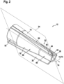
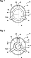
- figs 2 to 5 show a schematic representation of the anti-kink device 12 in different perspective views. Furthermore, the Figures 6 to 8 a schematic representation of the anti-kink device 12 in different sectional views.
- the anti-kink device 12 has a base body 14 .
- the base body 14 is free from rotational symmetry.
- the main body 14 has a main extension direction 16 .
- the base body 14 has a main extension 18 along the main extension direction 16 .
- the base body 14 also has a recess 74 .
- the recess 74 is designed to accommodate the endoscope shaft 10 .
- a smallest inner diameter of the recess 74 corresponds at least to a largest outer diameter of the endoscope shaft 10.
- the base body 14 has a jacket 76 .
- the shell 76 extends to the main extension 18 of the body 14.
- the shell 76 has an outer surface 78 on.
- the jacket 76 also has an inner surface 80 .
- the jacket 76 has a wall 82 .
- the wall 82 is delimited by the inner surface 80 and the outer surface 78 .
- the inner surface 80 delimits the recess 74.
- the wall 82 has a wall thickness.
- the wall thickness of the wall 80 is essentially constant along a main extension 18 of the base body 14 .
- the base body 14 is at least partially elastic. In the present case, the base body 14 is formed in one piece, at least to a large extent.
- the base body 14 has a shore value of at least 40. Furthermore, the base body 14 has a Shore value of at most 80. In the present case, the base body 14 has a Shore value of at least essentially 62.
- the base body 14 consists at least partially of a medical plastic.
- the base body consists at least to a large extent of a medical plastic.
- the medical grade plastic is designed to withstand autoclaving processes.
- the plastic is a thermoplastic elastomer.
- the thermoplastic elastomer is known under the brand name Mediprene.
- the base body 14 has at least one cylindrical section 48 (cf. 8 ). Cylindrical portion 48 is a distal portion of body 14. Recess 74 extends at least through cylindrical portion 48. Cylindrical portion 48 has an outer diameter. Furthermore, the cylindrical section 48 has an inner diameter. The inner diameter corresponds to an outer diameter of the endoscope shaft 10. The cylindrical section has an axis of rotational symmetry 72. The main extension direction 16 of the base body is offset at least parallel to the axis of rotational symmetry 72 .
- the base body 14 has at least one further cylindrical section 52 .
- the further cylindrical section 52 is a proximal section of the base body 14.
- the recess 74 extends through the further cylindrical section 52.
- the base body 14 has a circular cross section 54 (cf. 8 ).
- the further cylindrical section 52 has a further outer diameter.
- the further outer diameter of the cylindrical section 52 is larger than the outer diameter of the cylindrical section 48.
- the cylindrical section 52 has a further inner diameter.
- the other inner diameter corresponds at least essentially to an outer diameter of the handle 62.
- the other inner diameter of the other cylindrical section 52 is larger than the inner diameter of the cylindrical section 48.
- the other inner diameter of the other cylindrical section 52 is larger than the outer diameter of the cylindrical section 48.
- the base body 14 has an oval ring-shaped cross section 58 (cf. 6 ).
- the further cylindrical section 52 has an axis of rotational symmetry 73 .
- the main extension direction 16 of the base body is identical to the axis of rotational symmetry 73.
- the base body has at least one conical section 50 .
- the conical section 50 is a middle section of the base body 14.
- the recess 74 extends through the conical section 50.
- the conical section 50 is arranged between the cylindrical section 48 and the further cylindrical section 52.
- the conical section 50 connects the cylindrical section 48 and the further cylindrical section 52 to one another.
- the conical section 50 has an outer diameter.
- the outer diameter of the conical section increases along a main extension direction of the base body from the outer diameter of the cylindrical section 48 towards the further outer radius of the further cylindrical section 52.
- the conical section 50 has an inner radius.
- the inner radius of the conical section 50 increases from the inner radius of the cylindrical section 48 towards the further inner radius of the further cylindrical section 48. In the present case, the diameter increases continuously. Alternatively, the increase in diameter could be incremental.
- the base body 14 has an oval ring-shaped cross section 56 (cf. 6 ).
- the anti-kink device 12 has at least one connecting element 84 (cf. 4 ).
- the connecting element 84 is arranged on the base body 14 .
- Connector 84 is in section 52 arranged.
- the connecting element 84 is arranged on the inner surface 80 .
- the connecting element 84 is designed as an annular lip.
- the connecting element 84 is formed in one piece with the base body 14 . If the anti-kink device 12 is pushed onto the endoscope shaft 10 up to the handle 62 , the connecting element 84 connects the anti-kink device 12 to the handle 62 .
- the handle 62 has a connecting element 86 which corresponds to the connecting element 84 and which engages behind the connecting element 84 during a connection.
- the anti-kink device 12 has at least one locking element 88 (cf. 4 ).
- the anti-kink device has at least one further locking element 90 which is arranged at a distance from locking element 88 . Only one locking element 88 is described in more detail below. The description can be transferred to the further locking element 90 .
- the locking element 88 is arranged on the base body 14 .
- the locking element 88 is arranged in the section 48 .
- the locking element 88 is arranged on the inner surface 80 .
- the locking element 88 is designed as an annular lip.
- the locking element 88 is formed in one piece with the base body 14 . If the anti-kink device 12 is pushed onto the endoscope shaft 10, the locking element 88 jams with the endoscope shaft 10.
- the fin 26 has an extension 32 along the main extension direction 16 of the base body 14, which extends at least over 50% of the main extension 18 of the base body 14 (cf. 3 ). In the present case, the extent 18 of the fin 26 even extends over at least 80% of the main extent 18 of the base body 14.
- the fin 26 is formed at least partially from an elastic material.
- the elastic material has a shore value of at least 40. Furthermore, the elastic material has a Shore value of at most 80. In the present case, the elastic material has a Shore value of at least essentially 62.
- the material is a medical plastic.
- the material is a thermoplastic elastomer. In the present case, the material is known under the brand name Mediprene.
- the quick connector 22 has at least one additional fin 28 .
- the further fin 28 is designed at least essentially identically to the fin 26 .
- the quick connector 22 has at least one additional fin 30 .
- the additional fin 30 is designed at least essentially identically to the fin 26 . Accordingly, the quick connector 22 has a total of three fins 26, 28, 30.
- the quick connector 22 could include a different number of fins 26, 28, 30 than that shown here, for example to vary a clamping force.
- the fins 26, 28, 30 are arranged on the base body 14 in a rotationally symmetrical manner to one another.
- the fins 26, 28, 30 are arranged on the base body 14 in accordance with a triple rotational symmetry.
- the degree of rotational symmetry can be varied via the number of fins.
- a rotational symmetry axis 94 of the rotational symmetry of the fins 26, 28, 30 is different from the rotational symmetry axis 73.
- the rotational symmetry axis 94 is identical to the rotational symmetry axis 72.
- the rotational symmetry axis 94 of the fins 26, 28, 30 is parallel to the main extension direction 16 of the base body 14.
- the axis of rotational symmetry 94 of the fins 26, 28, 30 is offset parallel to the main direction of extension 16 of the base body 14.
- the method comprises at least one method step 120.
- method step 120 a mold is produced which corresponds to a negative of the desired anti-buckling device 12.
- the method includes at least one further method step 122.
- the material is liquefied.
- the material is put into the mold.
- the material is hardened in the mould.
- the kink protection 12 is formed.
- the method includes a further method step 124.
- the anti-buckling device 12 is removed from the mold.
- the anti-kink device 12 is then ready for use.
- the method comprises at least one method step 126.
- the endoscope shaft 10 is inserted into the recess 74 of the kink protector 12.
- the anti-kink device 12 is guided along the endoscope shaft 10 in the proximal direction.
- the anti-kink device 12 is guided along the endoscope shaft 10 until it reaches the handle 62 .
- the anti-kink device 12 is connected to the handle 62 .
- the method comprises at least one further method step 128.
- the tube 20 is guided onto the endoscope shaft 10.
- the tube 20 is guided onto the endoscope shaft 10 until the proximal end section of the tube 20 comes into contact with the anti-kink device 12 .
- the tube 22 can be dismantled by the tube 20 being subjected to a force in the distal direction which is greater than the clamping force acting on the fins 26 , 28 , 30 on the tube 20 .
- the tube 20 can be rotated relative to the kink protection 12 in order to overcome static friction of the fins 26, 28, 30 laterally in this way and thus reduce a clamping force acting on the inner wall of the tube.
Landscapes
- Health & Medical Sciences (AREA)
- Life Sciences & Earth Sciences (AREA)
- Surgery (AREA)
- Engineering & Computer Science (AREA)
- Biomedical Technology (AREA)
- Veterinary Medicine (AREA)
- Public Health (AREA)
- General Health & Medical Sciences (AREA)
- Animal Behavior & Ethology (AREA)
- Heart & Thoracic Surgery (AREA)
- Medical Informatics (AREA)
- Biophysics (AREA)
- Physics & Mathematics (AREA)
- Molecular Biology (AREA)
- Pathology (AREA)
- Optics & Photonics (AREA)
- Nuclear Medicine, Radiotherapy & Molecular Imaging (AREA)
- Radiology & Medical Imaging (AREA)
- Pulmonology (AREA)
- Mechanical Engineering (AREA)
- Emergency Medicine (AREA)
- Anesthesiology (AREA)
- Hematology (AREA)
- Otolaryngology (AREA)
- Physiology (AREA)
- Endoscopes (AREA)
Claims (17)
- Dispositif endoscopique ayant au moins une tige d'endoscope flexible (10) et ayant au moins une protection contre pliages (12) associée à la tige d'endoscope (10), qui comprend au moins un corps de base (14), qui est conçu de manière conique et/ou cylindrique au moins par sections et qui a une direction d'extension principale (16) et une extension principale (18) le long de la direction d'extension principale (16), et le protecteur contre pliages (12) comprend au moins un raccord rapide (22), qui est configuré pour se raccorder sélectivement à un tube (20) et qui a au moins une ailette (26, 28, 30) située au moins sensiblement perpendiculaire au corps de base (14), caractérisé en ce que l'ailette (26, 28, 30) a une extension (32), qui s'étend le long de la direction d'extension principale (16) du corps de base (14) au moins sur 50 % de l'extension principale (18) du corps de base (14).
- Dispositif endoscopique selon la revendication 1, caractérisé en ce qu'un plan d'extension principal (34) de l'ailette (26, 28, 30) est aligné au moins sensiblement parallèle à la direction d'extension principale (16) du corps de base (14).
- Dispositif endoscopique selon l'une des revendications précédentes, caractérisé en ce que l'ailette (26, 28, 30) a au moins un bord extérieur (36) orienté à l'opposé du corps de base (14), dans lequel au moins un angle (38, 40, 42) du bord extérieur (36) par rapport à la direction d'extension principale (16) du corps de base (14) diminue le long de son extension principale (18).
- Dispositif endoscopique selon l'une des revendications précédentes, caractérisé en ce que l'ailette (26, 28, 30) est configurée pour fléchir latéralement au contact, en particulier avec le tube (20).
- Dispositif endoscopique selon l'une des revendications précédentes, caractérisé en ce que l'ailette (26, 28, 30) est conçue pour être au moins partiellement élastique.
- Dispositif endoscopique selon l'une des revendications précédentes, caractérisé en ce que l'ailette (26, 28, 30) est constituée au moins partiellement d'un matériau qui a une valeur Shore d'au moins 40 et/ou d'au plus 80.
- Dispositif endoscopique selon l'une des revendications précédentes, caractérisé en ce que l'ailette (26, 28, 30) est constituée au moins partiellement d'un matériau qui est un élastomère thermoplastique.
- Dispositif endoscopique selon l'une des revendications précédentes, caractérisé en ce que l'ailette (26, 28, 30) a, par sections et mesurée au moins par rapport au corps de base (14), une hauteur (44) qui correspond au moins au double de l'épaisseur (46) de l'ailette (26, 28, 30).
- Dispositif endoscopique selon l'une des revendications précédentes, caractérisé en ce que le corps de base (14) a au moins une section conique (48, 52) et au moins une section cylindrique (50).
- Dispositif endoscopique selon l'une des revendications précédentes, caractérisé en ce que le corps de base (14) a, coupé perpendiculairement à sa direction principale d'extension (16), au moins par sections, une section transversale (54, 56) s'écartant d'une forme d'anneau circulaire.
- Dispositif endoscopique selon l'une des revendications précédentes, caractérisé en ce que l'ailette (26, 28, 30) est conçue d'un seul tenant avec le corps de base (14).
- Dispositif endoscopique selon l'une des revendications précédentes, caractérisé en ce que le raccord rapide (22) a au moins une ailette (26, 28, 30) supplémentaire, qui est conçue de manière sensiblement identique à l'ailette (26, 28, 30).
- Dispositif endoscopique selon la revendication 12, caractérisé en ce que l'ailette (26, 28, 30) et l'ailette (26, 28, 30) supplémentaire sont agencées sur le corps de base (14) de manière à être symétriques en rotation l'une par rapport à l'autre autour d'un axe de symétrie de rotation (72, 94).
- Dispositif endoscopique selon la revendication 13, caractérisé en ce que l'axe de symétrie de rotation (94) des ailettes (26, 28, 30) est différent de la direction d'extension principale (16) du corps de base (14).
- Dispositif endoscopique selon l'une des revendications précédentes, caractérisé par le tube (20).
- Endoscope (60) comprenant un dispositif endoscopique ayant au moins une tige d'endoscope flexible (10) et ayant au moins un protecteur contre pliages (12) associé à la tige d'endoscope (10), qui comprend au moins un corps de base (14), qui est conçu de manière conique et/ou cylindrique au moins par sections et qui a une direction d'extension principale (16) et une extension principale (18) le long de la direction d'extension principale (16), et le protecteur contre pliages (12) comprend au moins un raccord rapide (22), qui est configuré pour se raccorder sélectivement à un tube (20) et qui a au moins une ailette (26, 28, 30) située au moins sensiblement perpendiculaire au corps de base (14), caractérisé en ce que l'ailette (26, 28, 30) a une extension (32), qui s'étend le long de la direction d'extension principale (16) du corps de base (14) au moins sur 50 % de l'extension principale (18) du corps de base (14).
- Endoscope (60) selon la revendication 16, caractérisé en ce que le dispositif endoscopique comprend des caractéristiques supplémentaires selon l'une des revendications 2 à 15.
Applications Claiming Priority (1)
| Application Number | Priority Date | Filing Date | Title |
|---|---|---|---|
| DE102019111347.4A DE102019111347B4 (de) | 2019-05-02 | 2019-05-02 | Endoskopische Vorrichtung |
Publications (2)
| Publication Number | Publication Date |
|---|---|
| EP3733043A1 EP3733043A1 (fr) | 2020-11-04 |
| EP3733043B1 true EP3733043B1 (fr) | 2023-04-26 |
Family
ID=70476006
Family Applications (1)
| Application Number | Title | Priority Date | Filing Date |
|---|---|---|---|
| EP20171798.0A Active EP3733043B1 (fr) | 2019-05-02 | 2020-04-28 | Dispositif endoscopique |
Country Status (4)
| Country | Link |
|---|---|
| US (1) | US11678792B2 (fr) |
| EP (1) | EP3733043B1 (fr) |
| CN (1) | CN111870210A (fr) |
| DE (1) | DE102019111347B4 (fr) |
Families Citing this family (1)
| Publication number | Priority date | Publication date | Assignee | Title |
|---|---|---|---|---|
| DE102020130715A1 (de) | 2020-11-20 | 2022-05-25 | Karl Storz SE & Co. KG Intellectual Property | Endoskopische Vorrichtung |
Citations (1)
| Publication number | Priority date | Publication date | Assignee | Title |
|---|---|---|---|---|
| JP2002172118A (ja) * | 2000-12-08 | 2002-06-18 | Asahi Optical Co Ltd | 内視鏡用チューブ状処置具 |
Family Cites Families (13)
| Publication number | Priority date | Publication date | Assignee | Title |
|---|---|---|---|---|
| DE19636272A1 (de) * | 1996-09-06 | 1998-03-12 | Star Gmbh | Linearführungseinrichtung |
| US5906594A (en) * | 1997-01-08 | 1999-05-25 | Symbiosis Corporation | Endoscopic infusion needle having dual distal stops |
| JP3533081B2 (ja) * | 1998-04-10 | 2004-05-31 | ペンタックス株式会社 | 内視鏡用処置具の可撓性シースの連結構造 |
| US6464632B1 (en) * | 1999-02-13 | 2002-10-15 | James M. Taylor | Flexible inner liner for the working channel of an endoscope |
| DE20003797U1 (de) * | 1999-08-24 | 2000-06-29 | Storz Karl Gmbh & Co Kg | Flexibles Enkoskop mit Koppeleinrichtung für einen Tubus |
| US6454702B1 (en) * | 1999-10-14 | 2002-09-24 | Scimed Life Systems, Inc. | Endoscope and endoscopic instrument system having reduced backlash when moving the endoscopic instrument within a working channel of the endoscope |
| US6852078B2 (en) | 2002-05-22 | 2005-02-08 | Pentax Corporation | Outer sheathed endoscope |
| US7758497B2 (en) * | 2003-06-20 | 2010-07-20 | Contura A/S | Endoscopic attachment device |
| CN100435717C (zh) | 2003-06-20 | 2008-11-26 | 康图拉公司 | 内窥镜附属设备 |
| JP5121132B2 (ja) | 2005-11-02 | 2013-01-16 | オリンパスメディカルシステムズ株式会社 | 内視鏡システム、及び内視鏡用操作補助装置 |
| BRPI0922444A2 (pt) | 2008-12-10 | 2015-12-15 | Ambu As | mecanismo de controle da seção curvada do endoscópio |
| US20110230878A1 (en) * | 2010-03-16 | 2011-09-22 | Shawn Ryan | Ablation Handle Attachment |
| BR112015022230A2 (pt) * | 2013-03-11 | 2017-07-18 | Boston Scient Scimed Inc | manípulos de dispositivo médico e métodos de uso relacionados |
-
2019
- 2019-05-02 DE DE102019111347.4A patent/DE102019111347B4/de active Active
-
2020
- 2020-04-09 US US16/844,644 patent/US11678792B2/en active Active
- 2020-04-27 CN CN202010344035.2A patent/CN111870210A/zh active Pending
- 2020-04-28 EP EP20171798.0A patent/EP3733043B1/fr active Active
Patent Citations (1)
| Publication number | Priority date | Publication date | Assignee | Title |
|---|---|---|---|---|
| JP2002172118A (ja) * | 2000-12-08 | 2002-06-18 | Asahi Optical Co Ltd | 内視鏡用チューブ状処置具 |
Also Published As
| Publication number | Publication date |
|---|---|
| EP3733043A1 (fr) | 2020-11-04 |
| CN111870210A (zh) | 2020-11-03 |
| US20200345208A1 (en) | 2020-11-05 |
| DE102019111347B4 (de) | 2023-01-26 |
| US11678792B2 (en) | 2023-06-20 |
| DE102019111347A1 (de) | 2020-11-05 |
Similar Documents
| Publication | Publication Date | Title |
|---|---|---|
| DE60200308T2 (de) | Trocar mit verstärktem Obturator | |
| DE602005000994T2 (de) | Weibliches Steckverbindungselement | |
| EP2103265B1 (fr) | Joint pour un trocart | |
| WO2012116790A1 (fr) | Bouchon pour seringue et procédé de fabrication | |
| DE19911911A1 (de) | Verschlußelement für ein Endoskop | |
| EP0005865A2 (fr) | Système de liaison enfichable pour conduites sous pression, en particulier pour conduites de système de freinage | |
| EP0682921B1 (fr) | Pièce à main médicale ou dentaire | |
| EP3733043B1 (fr) | Dispositif endoscopique | |
| DE2822259C2 (de) | Schnellkupplung für rohrförmige Leitungen, insbesondere für Flüssigkeiten | |
| DE19619065C2 (de) | Trokarhülse mit einem Ventil | |
| EP1426669A2 (fr) | Tuyau ondulé et ensemble de raccordement pour celui-ci | |
| EP3586792B1 (fr) | Appareil dentaire destiné à examiner des espaces dentaires | |
| EP2392274B1 (fr) | Dispositif d'introduction d'un milieu ou d'un instrument dans le corps humain | |
| DE102020130715A1 (de) | Endoskopische Vorrichtung | |
| DE19543516A1 (de) | Transportelement für flächiges Gut | |
| DE2804618C2 (de) | Auf einer Gleitstange verschiebbarer Handbrausehalter | |
| EP1683543B1 (fr) | Système d'embase pour canule | |
| DE102017209389B4 (de) | Interdental-Reinigungsvorrichtung und Verfahren zur Herstellung einer Interdental-Reinigungsvorrichtung | |
| EP1303219B1 (fr) | Instrument medical, notamment resectoscope | |
| DE102020109867B4 (de) | Intraokularlinsen-Injektor mit spezifischer Einstechspitze einer Hohlnadel | |
| WO2005009517A1 (fr) | Seringue medicale pour injection | |
| DE3623367C2 (fr) | ||
| DE3503562A1 (de) | Quetschverbinder | |
| DE102009030313A1 (de) | Dilatationsvorrichtung zur perkutanen dilatativen Tracheostomie | |
| DE19730367B4 (de) | Elastomermanschette zur dichtenden Verbindung zweier Rohrenden |
Legal Events
| Date | Code | Title | Description |
|---|---|---|---|
| PUAI | Public reference made under article 153(3) epc to a published international application that has entered the european phase |
Free format text: ORIGINAL CODE: 0009012 |
|
| STAA | Information on the status of an ep patent application or granted ep patent |
Free format text: STATUS: THE APPLICATION HAS BEEN PUBLISHED |
|
| AK | Designated contracting states |
Kind code of ref document: A1 Designated state(s): AL AT BE BG CH CY CZ DE DK EE ES FI FR GB GR HR HU IE IS IT LI LT LU LV MC MK MT NL NO PL PT RO RS SE SI SK SM TR |
|
| AX | Request for extension of the european patent |
Extension state: BA ME |
|
| STAA | Information on the status of an ep patent application or granted ep patent |
Free format text: STATUS: REQUEST FOR EXAMINATION WAS MADE |
|
| 17P | Request for examination filed |
Effective date: 20210225 |
|
| RBV | Designated contracting states (corrected) |
Designated state(s): AL AT BE BG CH CY CZ DE DK EE ES FI FR GB GR HR HU IE IS IT LI LT LU LV MC MK MT NL NO PL PT RO RS SE SI SK SM TR |
|
| STAA | Information on the status of an ep patent application or granted ep patent |
Free format text: STATUS: EXAMINATION IS IN PROGRESS |
|
| 17Q | First examination report despatched |
Effective date: 20210520 |
|
| GRAP | Despatch of communication of intention to grant a patent |
Free format text: ORIGINAL CODE: EPIDOSNIGR1 |
|
| STAA | Information on the status of an ep patent application or granted ep patent |
Free format text: STATUS: GRANT OF PATENT IS INTENDED |
|
| RIC1 | Information provided on ipc code assigned before grant |
Ipc: A61B 1/267 20060101ALN20220420BHEP Ipc: A61B 1/00 20060101AFI20220420BHEP |
|
| INTG | Intention to grant announced |
Effective date: 20220510 |
|
| GRAJ | Information related to disapproval of communication of intention to grant by the applicant or resumption of examination proceedings by the epo deleted |
Free format text: ORIGINAL CODE: EPIDOSDIGR1 |
|
| STAA | Information on the status of an ep patent application or granted ep patent |
Free format text: STATUS: EXAMINATION IS IN PROGRESS |
|
| INTC | Intention to grant announced (deleted) | ||
| RIC1 | Information provided on ipc code assigned before grant |
Ipc: A61B 1/267 20060101ALN20220920BHEP Ipc: A61B 1/00 20060101AFI20220920BHEP |
|
| GRAP | Despatch of communication of intention to grant a patent |
Free format text: ORIGINAL CODE: EPIDOSNIGR1 |
|
| STAA | Information on the status of an ep patent application or granted ep patent |
Free format text: STATUS: GRANT OF PATENT IS INTENDED |
|
| RIC1 | Information provided on ipc code assigned before grant |
Ipc: A61B 1/267 20060101ALN20221024BHEP Ipc: A61B 1/00 20060101AFI20221024BHEP |
|
| INTG | Intention to grant announced |
Effective date: 20221115 |
|
| GRAS | Grant fee paid |
Free format text: ORIGINAL CODE: EPIDOSNIGR3 |
|
| GRAA | (expected) grant |
Free format text: ORIGINAL CODE: 0009210 |
|
| STAA | Information on the status of an ep patent application or granted ep patent |
Free format text: STATUS: THE PATENT HAS BEEN GRANTED |
|
| AK | Designated contracting states |
Kind code of ref document: B1 Designated state(s): AL AT BE BG CH CY CZ DE DK EE ES FI FR GB GR HR HU IE IS IT LI LT LU LV MC MK MT NL NO PL PT RO RS SE SI SK SM TR |
|
| REG | Reference to a national code |
Ref country code: GB Ref legal event code: FG4D Free format text: NOT ENGLISH |
|
| REG | Reference to a national code |
Ref country code: CH Ref legal event code: EP |
|
| REG | Reference to a national code |
Ref country code: DE Ref legal event code: R096 Ref document number: 502020003059 Country of ref document: DE |
|
| REG | Reference to a national code |
Ref country code: AT Ref legal event code: REF Ref document number: 1562253 Country of ref document: AT Kind code of ref document: T Effective date: 20230515 |
|
| REG | Reference to a national code |
Ref country code: IE Ref legal event code: FG4D Free format text: LANGUAGE OF EP DOCUMENT: GERMAN |
|
| P01 | Opt-out of the competence of the unified patent court (upc) registered |
Effective date: 20230527 |
|
| REG | Reference to a national code |
Ref country code: EE Ref legal event code: FG4A Ref document number: E023297 Country of ref document: EE Effective date: 20230531 |
|
| PGFP | Annual fee paid to national office [announced via postgrant information from national office to epo] |
Ref country code: IT Payment date: 20230501 Year of fee payment: 4 Ref country code: FR Payment date: 20230531 Year of fee payment: 4 Ref country code: EE Payment date: 20230601 Year of fee payment: 4 Ref country code: DE Payment date: 20230531 Year of fee payment: 4 Ref country code: CH Payment date: 20230605 Year of fee payment: 4 |
|
| REG | Reference to a national code |
Ref country code: LT Ref legal event code: MG9D |
|
| REG | Reference to a national code |
Ref country code: NL Ref legal event code: MP Effective date: 20230426 |
|
| PG25 | Lapsed in a contracting state [announced via postgrant information from national office to epo] |
Ref country code: NL Free format text: LAPSE BECAUSE OF FAILURE TO SUBMIT A TRANSLATION OF THE DESCRIPTION OR TO PAY THE FEE WITHIN THE PRESCRIBED TIME-LIMIT Effective date: 20230426 |
|
| PG25 | Lapsed in a contracting state [announced via postgrant information from national office to epo] |
Ref country code: SE Free format text: LAPSE BECAUSE OF FAILURE TO SUBMIT A TRANSLATION OF THE DESCRIPTION OR TO PAY THE FEE WITHIN THE PRESCRIBED TIME-LIMIT Effective date: 20230426 Ref country code: PT Free format text: LAPSE BECAUSE OF FAILURE TO SUBMIT A TRANSLATION OF THE DESCRIPTION OR TO PAY THE FEE WITHIN THE PRESCRIBED TIME-LIMIT Effective date: 20230828 Ref country code: NO Free format text: LAPSE BECAUSE OF FAILURE TO SUBMIT A TRANSLATION OF THE DESCRIPTION OR TO PAY THE FEE WITHIN THE PRESCRIBED TIME-LIMIT Effective date: 20230726 Ref country code: ES Free format text: LAPSE BECAUSE OF FAILURE TO SUBMIT A TRANSLATION OF THE DESCRIPTION OR TO PAY THE FEE WITHIN THE PRESCRIBED TIME-LIMIT Effective date: 20230426 |
|
| PG25 | Lapsed in a contracting state [announced via postgrant information from national office to epo] |
Ref country code: RS Free format text: LAPSE BECAUSE OF FAILURE TO SUBMIT A TRANSLATION OF THE DESCRIPTION OR TO PAY THE FEE WITHIN THE PRESCRIBED TIME-LIMIT Effective date: 20230426 Ref country code: PL Free format text: LAPSE BECAUSE OF FAILURE TO SUBMIT A TRANSLATION OF THE DESCRIPTION OR TO PAY THE FEE WITHIN THE PRESCRIBED TIME-LIMIT Effective date: 20230426 Ref country code: LV Free format text: LAPSE BECAUSE OF FAILURE TO SUBMIT A TRANSLATION OF THE DESCRIPTION OR TO PAY THE FEE WITHIN THE PRESCRIBED TIME-LIMIT Effective date: 20230426 Ref country code: LT Free format text: LAPSE BECAUSE OF FAILURE TO SUBMIT A TRANSLATION OF THE DESCRIPTION OR TO PAY THE FEE WITHIN THE PRESCRIBED TIME-LIMIT Effective date: 20230426 Ref country code: IS Free format text: LAPSE BECAUSE OF FAILURE TO SUBMIT A TRANSLATION OF THE DESCRIPTION OR TO PAY THE FEE WITHIN THE PRESCRIBED TIME-LIMIT Effective date: 20230826 Ref country code: HR Free format text: LAPSE BECAUSE OF FAILURE TO SUBMIT A TRANSLATION OF THE DESCRIPTION OR TO PAY THE FEE WITHIN THE PRESCRIBED TIME-LIMIT Effective date: 20230426 Ref country code: GR Free format text: LAPSE BECAUSE OF FAILURE TO SUBMIT A TRANSLATION OF THE DESCRIPTION OR TO PAY THE FEE WITHIN THE PRESCRIBED TIME-LIMIT Effective date: 20230727 |
|
| PG25 | Lapsed in a contracting state [announced via postgrant information from national office to epo] |
Ref country code: LU Free format text: LAPSE BECAUSE OF NON-PAYMENT OF DUE FEES Effective date: 20230428 Ref country code: FI Free format text: LAPSE BECAUSE OF FAILURE TO SUBMIT A TRANSLATION OF THE DESCRIPTION OR TO PAY THE FEE WITHIN THE PRESCRIBED TIME-LIMIT Effective date: 20230426 |
|
| REG | Reference to a national code |
Ref country code: BE Ref legal event code: MM Effective date: 20230430 |
|
| PG25 | Lapsed in a contracting state [announced via postgrant information from national office to epo] |
Ref country code: SK Free format text: LAPSE BECAUSE OF FAILURE TO SUBMIT A TRANSLATION OF THE DESCRIPTION OR TO PAY THE FEE WITHIN THE PRESCRIBED TIME-LIMIT Effective date: 20230426 |
|
| PG25 | Lapsed in a contracting state [announced via postgrant information from national office to epo] |
Ref country code: MC Free format text: LAPSE BECAUSE OF FAILURE TO SUBMIT A TRANSLATION OF THE DESCRIPTION OR TO PAY THE FEE WITHIN THE PRESCRIBED TIME-LIMIT Effective date: 20230426 |
|
| REG | Reference to a national code |
Ref country code: DE Ref legal event code: R097 Ref document number: 502020003059 Country of ref document: DE |
|
| PG25 | Lapsed in a contracting state [announced via postgrant information from national office to epo] |
Ref country code: SM Free format text: LAPSE BECAUSE OF FAILURE TO SUBMIT A TRANSLATION OF THE DESCRIPTION OR TO PAY THE FEE WITHIN THE PRESCRIBED TIME-LIMIT Effective date: 20230426 Ref country code: SK Free format text: LAPSE BECAUSE OF FAILURE TO SUBMIT A TRANSLATION OF THE DESCRIPTION OR TO PAY THE FEE WITHIN THE PRESCRIBED TIME-LIMIT Effective date: 20230426 Ref country code: RO Free format text: LAPSE BECAUSE OF FAILURE TO SUBMIT A TRANSLATION OF THE DESCRIPTION OR TO PAY THE FEE WITHIN THE PRESCRIBED TIME-LIMIT Effective date: 20230426 Ref country code: MC Free format text: LAPSE BECAUSE OF FAILURE TO SUBMIT A TRANSLATION OF THE DESCRIPTION OR TO PAY THE FEE WITHIN THE PRESCRIBED TIME-LIMIT Effective date: 20230426 Ref country code: DK Free format text: LAPSE BECAUSE OF FAILURE TO SUBMIT A TRANSLATION OF THE DESCRIPTION OR TO PAY THE FEE WITHIN THE PRESCRIBED TIME-LIMIT Effective date: 20230426 Ref country code: CZ Free format text: LAPSE BECAUSE OF FAILURE TO SUBMIT A TRANSLATION OF THE DESCRIPTION OR TO PAY THE FEE WITHIN THE PRESCRIBED TIME-LIMIT Effective date: 20230426 |
|
| REG | Reference to a national code |
Ref country code: IE Ref legal event code: MM4A |
|
| PG25 | Lapsed in a contracting state [announced via postgrant information from national office to epo] |
Ref country code: BE Free format text: LAPSE BECAUSE OF NON-PAYMENT OF DUE FEES Effective date: 20230430 |
|
| PLBE | No opposition filed within time limit |
Free format text: ORIGINAL CODE: 0009261 |
|
| STAA | Information on the status of an ep patent application or granted ep patent |
Free format text: STATUS: NO OPPOSITION FILED WITHIN TIME LIMIT |
|
| 26N | No opposition filed |
Effective date: 20240129 |
|
| PG25 | Lapsed in a contracting state [announced via postgrant information from national office to epo] |
Ref country code: IE Free format text: LAPSE BECAUSE OF NON-PAYMENT OF DUE FEES Effective date: 20230428 |
|
| PG25 | Lapsed in a contracting state [announced via postgrant information from national office to epo] |
Ref country code: IE Free format text: LAPSE BECAUSE OF NON-PAYMENT OF DUE FEES Effective date: 20230428 |
|
| PG25 | Lapsed in a contracting state [announced via postgrant information from national office to epo] |
Ref country code: SI Free format text: LAPSE BECAUSE OF FAILURE TO SUBMIT A TRANSLATION OF THE DESCRIPTION OR TO PAY THE FEE WITHIN THE PRESCRIBED TIME-LIMIT Effective date: 20230426 |