EP3732330B1 - Véhicule de transport des traverses de chemin de fer - Google Patents
Véhicule de transport des traverses de chemin de fer Download PDFInfo
- Publication number
- EP3732330B1 EP3732330B1 EP18833231.6A EP18833231A EP3732330B1 EP 3732330 B1 EP3732330 B1 EP 3732330B1 EP 18833231 A EP18833231 A EP 18833231A EP 3732330 B1 EP3732330 B1 EP 3732330B1
- Authority
- EP
- European Patent Office
- Prior art keywords
- transport vehicle
- loading
- sleeper
- pallets
- sleeper transport
- Prior art date
- Legal status (The legal status is an assumption and is not a legal conclusion. Google has not performed a legal analysis and makes no representation as to the accuracy of the status listed.)
- Active
Links
- 241001669679 Eleotris Species 0.000 title claims description 64
- 230000008878 coupling Effects 0.000 claims description 12
- 238000010168 coupling process Methods 0.000 claims description 12
- 238000005859 coupling reaction Methods 0.000 claims description 12
- 238000000034 method Methods 0.000 claims description 12
- 239000013590 bulk material Substances 0.000 claims description 3
- 238000010276 construction Methods 0.000 description 4
- 238000003860 storage Methods 0.000 description 4
- 238000005253 cladding Methods 0.000 description 2
- 230000002349 favourable effect Effects 0.000 description 2
- 230000005540 biological transmission Effects 0.000 description 1
- 238000002485 combustion reaction Methods 0.000 description 1
- 230000001419 dependent effect Effects 0.000 description 1
- 238000000151 deposition Methods 0.000 description 1
- 238000006073 displacement reaction Methods 0.000 description 1
- 230000000694 effects Effects 0.000 description 1
- 238000005516 engineering process Methods 0.000 description 1
- 239000000463 material Substances 0.000 description 1
- 230000000284 resting effect Effects 0.000 description 1
- 238000005096 rolling process Methods 0.000 description 1
Images

Classifications
-
- E—FIXED CONSTRUCTIONS
- E01—CONSTRUCTION OF ROADS, RAILWAYS, OR BRIDGES
- E01B—PERMANENT WAY; PERMANENT-WAY TOOLS; MACHINES FOR MAKING RAILWAYS OF ALL KINDS
- E01B29/00—Laying, rebuilding, or taking-up tracks; Tools or machines therefor
- E01B29/06—Transporting, laying, removing or renewing sleepers
-
- B—PERFORMING OPERATIONS; TRANSPORTING
- B61—RAILWAYS
- B61D—BODY DETAILS OR KINDS OF RAILWAY VEHICLES
- B61D3/00—Wagons or vans
- B61D3/02—Wagons or vans with multiple deck arrangements
-
- B—PERFORMING OPERATIONS; TRANSPORTING
- B61—RAILWAYS
- B61D—BODY DETAILS OR KINDS OF RAILWAY VEHICLES
- B61D3/00—Wagons or vans
- B61D3/10—Articulated vehicles
-
- B—PERFORMING OPERATIONS; TRANSPORTING
- B61—RAILWAYS
- B61D—BODY DETAILS OR KINDS OF RAILWAY VEHICLES
- B61D3/00—Wagons or vans
- B61D3/10—Articulated vehicles
- B61D3/14—Articulated vehicles comprising running gear interconnected by load supports facilitating low-level load transport
-
- B—PERFORMING OPERATIONS; TRANSPORTING
- B61—RAILWAYS
- B61D—BODY DETAILS OR KINDS OF RAILWAY VEHICLES
- B61D3/00—Wagons or vans
- B61D3/16—Wagons or vans adapted for carrying special loads
-
- B—PERFORMING OPERATIONS; TRANSPORTING
- B61—RAILWAYS
- B61D—BODY DETAILS OR KINDS OF RAILWAY VEHICLES
- B61D47/00—Loading or unloading devices combined with vehicles, e.g. loading platforms, doors convertible into loading and unloading ramps
-
- B—PERFORMING OPERATIONS; TRANSPORTING
- B61—RAILWAYS
- B61D—BODY DETAILS OR KINDS OF RAILWAY VEHICLES
- B61D49/00—Other details
-
- B—PERFORMING OPERATIONS; TRANSPORTING
- B65—CONVEYING; PACKING; STORING; HANDLING THIN OR FILAMENTARY MATERIAL
- B65G—TRANSPORT OR STORAGE DEVICES, e.g. CONVEYORS FOR LOADING OR TIPPING, SHOP CONVEYOR SYSTEMS OR PNEUMATIC TUBE CONVEYORS
- B65G67/00—Loading or unloading vehicles
- B65G67/02—Loading or unloading land vehicles
- B65G67/04—Loading land vehicles
- B65G67/10—Loading land vehicles using conveyors covering the whole length of vehicle trains
-
- B—PERFORMING OPERATIONS; TRANSPORTING
- B61—RAILWAYS
- B61F—RAIL VEHICLE SUSPENSIONS, e.g. UNDERFRAMES, BOGIES OR ARRANGEMENTS OF WHEEL AXLES; RAIL VEHICLES FOR USE ON TRACKS OF DIFFERENT WIDTH; PREVENTING DERAILING OF RAIL VEHICLES; WHEEL GUARDS, OBSTRUCTION REMOVERS OR THE LIKE FOR RAIL VEHICLES
- B61F3/00—Types of bogies
- B61F3/02—Types of bogies with more than one axle
- B61F3/04—Types of bogies with more than one axle with driven axles or wheels
-
- B—PERFORMING OPERATIONS; TRANSPORTING
- B65—CONVEYING; PACKING; STORING; HANDLING THIN OR FILAMENTARY MATERIAL
- B65G—TRANSPORT OR STORAGE DEVICES, e.g. CONVEYORS FOR LOADING OR TIPPING, SHOP CONVEYOR SYSTEMS OR PNEUMATIC TUBE CONVEYORS
- B65G2814/00—Indexing codes relating to loading or unloading articles or bulk materials
- B65G2814/03—Loading or unloading means
- B65G2814/0301—General arrangements
- B65G2814/0311—Other article loading or unloading devices
- B65G2814/0313—Other article loading or unloading devices with vertically reciprocating platforms
-
- B—PERFORMING OPERATIONS; TRANSPORTING
- B65—CONVEYING; PACKING; STORING; HANDLING THIN OR FILAMENTARY MATERIAL
- B65G—TRANSPORT OR STORAGE DEVICES, e.g. CONVEYORS FOR LOADING OR TIPPING, SHOP CONVEYOR SYSTEMS OR PNEUMATIC TUBE CONVEYORS
- B65G2814/00—Indexing codes relating to loading or unloading articles or bulk materials
- B65G2814/03—Loading or unloading means
- B65G2814/0347—Loading or unloading means for cars or linked car-trains with individual load-carriers
-
- B—PERFORMING OPERATIONS; TRANSPORTING
- B65—CONVEYING; PACKING; STORING; HANDLING THIN OR FILAMENTARY MATERIAL
- B65G—TRANSPORT OR STORAGE DEVICES, e.g. CONVEYORS FOR LOADING OR TIPPING, SHOP CONVEYOR SYSTEMS OR PNEUMATIC TUBE CONVEYORS
- B65G67/00—Loading or unloading vehicles
- B65G67/02—Loading or unloading land vehicles
- B65G67/04—Loading land vehicles
- B65G67/22—Loading moving vehicles
Definitions
- the invention relates to a sleeper transport vehicle, comprising a loading area which has a lower load-bearing loading level and an upper load-bearing loading level, with a guide being arranged in each loading level, in which pallets are guided in the longitudinal direction of the sleeper transport vehicle, with a transfer area being arranged on a front side, into which the guides protrude in order to pass on pallets with new sleepers in one loading level to another sleeper transport vehicle or loading/unloading vehicle arranged at the front and to record pallets with old sleepers in the other loading level.
- the invention also relates to a method for providing new clamps or for picking up old sleepers by means of a sleeper transport vehicle.
- a sleeper transport vehicle which has two loading levels and a lifting device at the end.
- pallets are loaded with new sleepers, which are discharged at an unloading point via a discharge device controlled by an operator tilted and thereby thrown next to a track. Due to the unloading next to the track, this solution is not suitable for an assembly line laying train.
- the WO 2012/156408 A1 shows a system for rail-bound transport of objects such as sleepers.
- This system includes rail-bound transport vehicles on which the objects to be transported are stored in containers on two levels. Several of these transport vehicles form a train, with transfer areas being present at the respective ends of the vehicle.
- the invention is based on the object of specifying an improvement over the prior art for a sleeper transport vehicle of the type mentioned at the outset.
- the invention relates to a method for operating a sleeper transport vehicle.
- the stated object is achieved according to the invention by the combination of features according to claim 1 .
- the object directed to a method is achieved according to the invention by the combination of features according to claim 12 .
- Dependent claims specify advantageous refinements of the invention.
- the invention provides that a sliding device for sliding the pallets along the guides is arranged in each loading level.
- the respective sliding device is designed as at least one circulating chain that projects into the transfer area, with coupling elements being arranged on the pallets for temporary coupling to the chain.
- the circulating chain represents a reliable solution for shifting the pallets on one of the loading levels.
- the coupling elements are simply positioned on the chain at a required distance.
- the respective guide is designed as a longitudinal profile and guide rollers are arranged on the pallets for guiding along the longitudinal profile. Low-friction pallet guidance is ensured by rolling the pallets over the guide rollers in the longitudinal profiles.
- each pallet has longitudinal supports on its underside for resting on a roller conveyor.
- the pallets are very robust and simply constructed. In addition, they are maintenance-free because all moving parts (bearings, rollers) are located on the vehicle.
- each pallet is assigned a locking device for temporary fixation during transport. This keeps the pallets and sleepers securely in place when driving to and from a construction site.
- the transport vehicle comprises a wagon frame which is supported on bogies, with at least one bogie being designed as a powered bogie.
- the transport vehicle moves independently, which has an advantageous effect on the automation of the work assignment.
- the transport vehicle has cladding elements on both longitudinal sides. If the sleepers slip sideways within the pallet, they are still held securely within the sleeper transport vehicle and thus within the clearance profile.
- the transport vehicle has a supporting conveyor level above the upper loading level, in which at least one longitudinal conveyor belt for transport of bulk material is arranged. This means that bulk material can also be fed in or removed when the sleeper is replaced.
- a lifting/lowering device for lifting or lowering a pallet from one loading level to the other loading level is arranged on the end face opposite the transfer area. This enables the pallets to be transported further across both loading levels when unloading new sleepers or loading old sleepers. In this way, both loading levels can be used for the delivery of new sleepers or the removal of old sleepers.
- a further increase in the loading capacity is advantageously achieved in that the transport vehicle comprises at least two wagon frames which are articulated to one another, that each wagon frame is assigned its own loading area and that the loading areas are coupled to a transfer area, in which the respective guides and the respective Sliding devices protrude to move the pallets lengthwise across both loading areas.
- the loading capacity can be flexibly adjusted by such an articulated arrangement of several wagon frames.
- the maximum length of the wagon frame is specified by a minimum track radius that can be driven through and a clearance profile that must be observed.
- the method according to the invention for providing new clamps or for picking up old sleepers by means of a sleeper transport vehicle provides that in the transfer area the pallets with new sleepers that have been pushed further in one loading level are transferred from the sleeper transport vehicle to the loading/unloading vehicle and that in the other loading level pallets with old sleepers are transferred from the loading/unloading vehicle to the sleeper transport vehicle. In this way, an assembly line supply of new sleepers and a similar removal of old sleepers takes place.
- pallets are raised or lowered from one loading level to the other loading level by means of a lifting/lowering device arranged on the end face opposite the transfer area. This turns both loading levels into one rotational supply of new sleepers and inclusion of old sleepers included. The pallets move in opposite directions on the loading level, with the lifting/lowering device being used to transfer them between the loading levels.
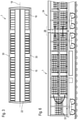
- FIGS 1-3 show different views of a sleeper transport vehicle 1, which can be moved on a track 2.
- the sleeper transport vehicle 1 comprises a wagon frame 4 supported on bogies 3, on which lateral uprights 5 and transverse and longitudinal beams 6 connected to them are arranged.
- a lower supporting loading level 7 and an upper supporting loading level 8 are formed.
- pallets are 9 in Displaceable in the longitudinal direction of the sleeper transport vehicle 1 along a guide 10 by means of a sliding device 11 .
- Each pallet 9 comprises a carrier frame 12 which is supported on longitudinal supports 13.
- the longitudinal supports 13 are advantageously designed like runners and lie on roller conveyors 14 of the respective loading level 7.8.
- the support frame 12 is designed to accommodate sleepers 15, 16 in several layers arranged one above the other. 1 shows a sleeper transport vehicle 1 on which seven pallets with new sleepers 15 and already one pallet with old sleepers 16 are loaded. In this exemplary loading condition, a pallet 9 with new sleepers 15 has already been passed on and the pallet 9 with old sleepers 16 has been added.
- each pallet 9 has limits 17 at the front and rear, which extend to the top layer of the sleepers 15, 16.
- the respective pallet 9 is guided in the guide 10 designed as a longitudinal profile by means of two guide rollers 18 .
- a groove is arranged in a longitudinal axis of symmetry 19 of the sleeper transport vehicle 1 in each loading plane 7 , 8 .
- cladding elements 30 are arranged on both longitudinal sides of the sleeper transport vehicle. These are in 1 and 6 not shown to show internal structure.
- each loading level 7 , 8 two chains with coupling elements 20 circulating in a horizontal plane are provided as a pushing device 11 for pushing the pallets 9 along the guide 10 .
- the chains are arranged on both sides of the axis of symmetry 19 and have opposite directions of rotation during operation.
- the respective outer chain strand is temporarily coupled to the pallets 9 located on the corresponding loading level 7, 8 and pushes them forward.
- each pallet 9 is equipped with a locking device 21 that can be released by remote control and is designed to fix the pallets 9 during transport.
- This can be designed, for example, as a locking bolt that secures the pallet 9 in question fixed.
- the two circulating chains are blocked in the longitudinal direction in order to fix all the pallets 9 in their position by means of the coupling elements 20 .
- ballast can be brought in and old ballast removed at the same time.
- the old ballast is dropped, for example, into a container wagon adjacent to the vehicle combination.
- a supply unit 23 is positioned below the carriage frame 4. This serves both to supply energy to various drives 24 for the circulating chains, the longitudinal conveyor belts 22 and, if necessary, for a bogie 3 designed as a motor bogie.
- the drives 24 are designed, for example, as hydraulic drives, with the supply unit 23 comprising a motor and hydraulic pumps.
- electric drives 24 are provided.
- the supply unit 23 comprises an internal combustion engine/generator unit and optionally an accumulator for temporarily storing electrical energy.
- a central control device 35 is provided in order to coordinate the individual movement sequences.
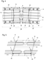
- In 4 are two loading areas 25 which are coupled to a transfer area 26 .
- the pallets 9 are transferred from one loading area 25 to the next.
- the two loading areas 25 are located on two carriage frames 4 which are articulated to one another.
- a corresponding transfer area 26 to a loading/unloading vehicle 34 is also provided at the end of the sleeper transport vehicle 1 .
- a problem-free pallet transfer is also possible during cornering if the two loading areas 25 are not aligned.
- the respective pallet 9 is continuously guided in a guide 10 with at least one guide roller 18 because the guide 10 of the respective loading area 25 protrudes into the transfer area 26 .
- the respective loading area 25 is to be regarded as the zone in which during transport to or from the construction site Pallets 9 are stored.
- the respective transfer area 26 overlaps with the end zones of the coupled loading areas 25 and is shorter in its longitudinal extent than the length of a pallet.
- the respective sliding device 11 also protrudes into the transfer area 26, so that the respective pallet 9 is continuously coupled to at least one sliding device 11 during a transfer.
- the sliding devices 11 embodied as chains
- the chain strand that is moved in a conveying direction 27 is coupled to the pallets 9 .
- the distance between the individual coupling elements 20 of the respective chain is selected in such a way that the pallets 9 are pushed on uniformly in the transfer area 26 .
- the coupling elements 20 are designed, for example, as chain link extensions which act only in the conveying direction 27 at entrainment points of the pallets 9 .
- the respective pallet 9 is first pushed from the delivering loading area 25 into the transfer area 26 by means of coupling elements 20 acting on the rear end 28 of the pallet.
- Buffer elements 31 are also usefully arranged on each pallet 9, by means of which a pallet 9 is pushed further in the conveying direction 27 by a pallet 9 that follows.
- the transport capacity of the sleeper transport vehicle 1 can be adapted to a given construction site situation by the articulated connection of several wagon frames 4 by means of a respective connecting joint 32 .
- the sleeper transport vehicle 1 can be integrated into a vehicle combination in order to cover different usage variants.
- a lifting/lowering device 33 is arranged on a rear end face of the sleeper transport vehicle 1 .
- This can be designed as a simple lifting platform.
- a loading/unloading vehicle 34 is coupled to the front end. This also includes loading levels 7, 8, via which sleepers 15, 16 are conveyed to a sleeper storage device (not shown) or from a sleeper receiving device.
- a crane-like loading/unloading device can remove new sleepers 15 from a lower pallet 9 directly in the transfer area, then place old sleepers 16 on the pallet 9 and lift the pallet 9 onto the upper loading level 8 .
- both loading levels 7, 8 of the sleeper transport vehicle 1 are loaded with new sleepers 15.
- the loading/unloading vehicle 34 removes a pallet 9 with new sleepers 15 from the lower loading level 7 . This frees up a pallet space at the rear end. A pallet 9 is lowered onto this from the upper loading level 8 by means of a lifting and lowering device 33 .
- pallets 9 are pushed backwards on the upper loading level 8 and in the transfer area 26 a pallet 9 equipped with old sleepers 16 is transferred from the loading/unloading vehicle 34 to the sleeper transport vehicle 1.
- the work cycle is repeated until both loading levels 7, 8 are fully loaded with old sleepers 16. If necessary, the conveying direction 27 can also be reversed, so that new sleepers 15 are transferred from the upper loading level 8 to the loading/unloading vehicle 34 .
- Movements of the pallets 9 are recorded by sensors and are fed to the central control device 35 .
- the control device 35 is set up for automated coordination of the individual movement sequences. During a work assignment, a continuous forward drive takes place, which is coordinated with the working speed of the sleeper depositing device or the sleeper receiving device. In this way, I move the sleeper transport vehicle 1 in association with a laying train along the track 2.
- the sleeper transport vehicle 1 Before starting work, the sleeper transport vehicle 1 is loaded at a storage location with pallets 9 that are fitted with new sleepers 15 . This process is also carried out according to the rotation principle described, using a lifting and lowering device 33 at the front. An unloading process takes place in a corresponding manner after the old sleepers 15 have been transported away. A sleeper transport vehicle 1 combined unloading of old sleepers 15 and loading of new sleepers 16 can also be useful at the storage location if several work assignments take place in a row.
- the sleeper transport vehicle 1 does not include a lifting and lowering device 33. Then only one loading level 7, 8 is loaded with pallets 9, which are equipped with new sleepers 15, before work begins. In the course of the assembly line unloading of the new sleepers 15 on the construction site, the other loading level 8, 7 is loaded with old sleepers 16. This is followed by transport to a storage location where the old sleepers 16 are unloaded.
- the sleeper transport vehicle 1 can be composed of several vehicle units, each with its own traction drive 24 .
- a connecting link 32 for the transmission of tractive forces can be omitted between such vehicle units.
- This increases flexibility in material logistics. Only during a pallet transport in the loading levels 7, 8 are the vehicle units lined up and drive together in the working direction. The vehicle units are coordinated with one another via radio links. Otherwise, the vehicle units can be moved separately. move at the same speed. As soon as a sleeper transport vehicle 1 is fully loaded with old sleepers 16, this could automatically be removed from the vehicle network and exchanged for a sleeper transport vehicle 1 loaded with new sleepers 15. In the case of automation, this would result in greater flexibility and coupling would only be necessary for a transfer journey or transport journey.
Claims (14)
- Véhicule de transport de traverses (1), comprenant une région de chargement (25) qui présente un plan de chargement porteur inférieur (7) et un plan de chargement porteur supérieur (8), dans lequel un guide (10) dans lequel des palettes (9) sont guidées dans la direction longitudinale du véhicule de transport de traverses (1) est disposé dans chaque plan de chargement (7, 8), dans lequel une région de transfert (26) dans laquelle les guides (10) avancent est disposée sur un côté frontal pour transmettre lors d'un déploiement des palettes (9) avec de nouvelles traverses (15) dans un plan de chargement (7, 8) à un autre véhicule de transport de traverses (1) ou un véhicule de chargement/déchargement (34) disposé côté frontal ainsi que recevoir des palettes avec d'anciennes traverses (16) dans l'autre plan de chargement (7, 8), caractérisé en ce qu'un dispositif de coulissement (11) pour le coulissement des palettes (9) le long du guide (10) est réalisé dans chaque plan de chargement (7, 8) en tant qu'au moins une chaîne circulante, avançant dans la région de transfert, et que des éléments de couplage (20) sont disposés sur les palettes (9) pour le couplage transitoire à la chaîne.
- Véhicule de transport de traverses (1) selon la revendication 1, caractérisé en ce qu'une chaîne circulante est à chaque fois disposée dans chaque plan de chargement (7, 8) des deux côtés d'un axe de symétrie longitudinal (19).
- Véhicule de transport de traverses (1) selon la revendication 1 ou 2, caractérisé en ce que le guide respectif (10) est réalisé en tant que profilé longitudinal et que des rouleaux de guidage (18) pour le guidage le long du profilé longitudinal sont disposés sur la palette (9).
- Véhicule de transport de traverses (1) selon une des revendications 1 à 3, caractérisé en ce que chaque palette (9) comprend sur son côté inférieur des appuis longitudinaux (13) pour l'appui sur un transporteur à rouleaux (14).
- Véhicule de transport de traverses (1) selon la revendication 4, caractérisé en ce qu'un guide s'étendant au milieu (10) est disposé dans chaque plan de chargement (7, 8) et un transporteur à rouleaux (14) est à chaque fois disposé des deux côtés de ce guide (10).
- Véhicule de transport de traverses (1) selon une des revendications 1 à 5, caractérisé en ce qu'un dispositif de verrouillage (21) pour la fixation transitoire pendant un trajet de transport est associé à chaque palette (9).
- Véhicule de transport de traverses (1) selon une des revendications 1 à 6, caractérisé en ce que le véhicule de transport (1) comprend un châssis de wagon (4) qui est appuyé sur des bogies (3) et qu'au moins un bogie (3) est réalisé en tant que bogie moteur.
- Véhicule de transport de traverses (1) selon une des revendications 1 à 7, caractérisé en ce que le véhicule de transport (1) présente des éléments de panneautage (30) sur les deux côtés longitudinaux.
- Véhicule de transport de traverses (1) selon une des revendications 1 à 8, caractérisé en ce que le véhicule de transport (1) présente au-dessus du plan de chargement supérieur (8) un plan de transport porteur dans lequel au moins une bande transporteuse longitudinale (22) est disposée pour le transport de marchandise en vrac.
- Véhicule de transport de traverses (1) selon une des revendications 1 à 9, caractérisé en ce qu'un dispositif de levage/abaissement (33) pour le levage ou l'abaissement d'une palette (9) d'un plan de chargement (7, 8) dans l'autre plan de chargement (7, 8) est disposé sur le côté frontal opposé à la région de transfert (26).
- Véhicule de transport de traverses (1) selon une des revendications 1 à 10, caractérisé en ce que le véhicule de transport (1) comprend au moins deux châssis de wagon (4) qui sont connectés l'un à l'autre de manière articulée, qu'une région de chargement propre (25) est associée à chaque châssis de wagon (4) et que les régions de chargement (25) sont couplées à une région de transfert (26) dans laquelle les guides respectifs (10) et les dispositifs de coulissement respectifs (11) avancent pour faire coulisser plus loin en direction longitudinale les palettes (9) par-dessus les deux régions de chargement (25).
- Procédé de mise à disposition de nouvelles traverses (15) ou de réception d'anciennes traverses (16) au moyen d'un véhicule de transport de traverses (1) selon une des revendications 1 à 11, caractérisé en ce que les palettes (9) coulissées plus loin dans un des plans de chargement (7, 8) avec de nouvelles traverses (15) sont transférées du véhicule de transport de traverses (1) au véhicule de chargement/déchargement dans la région de transfert (26) et que des palettes (9) avec d'anciennes traverses (16) sont transférées du véhicule de chargement/déchargement (34) au véhicule de transport de traverses (1) dans l'autre plan de chargement (7, 8).
- Procédé selon la revendication 12, caractérisé en ce que des palettes (9) sont levées ou abaissées d'un plan de chargement (7, 8) dans l'autre plan de chargement (7, 8) au moyen d'un dispositif de levage/abaissement disposé sur le côté frontal opposé à la région de transfert (26).
- Procédé selon la revendication 12 ou 13, caractérisé en ce que le véhicule de transport de traverses (1) est déplacé pendant un transfert de palettes conjointement au véhicule de chargement/déchargement (34) avec une vitesse de travail prédéfinie le long d'une voie ferrée (2) dont les traverses (15, 16) sont échangées au moyen d'un dispositif d'échange de traverses.
Applications Claiming Priority (2)
| Application Number | Priority Date | Filing Date | Title |
|---|---|---|---|
| AT5012017 | 2017-12-28 | ||
| PCT/EP2018/086467 WO2019129678A1 (fr) | 2017-12-28 | 2018-12-21 | Véhicule de transport des traverses de chemin de fer |
Publications (2)
| Publication Number | Publication Date |
|---|---|
| EP3732330A1 EP3732330A1 (fr) | 2020-11-04 |
| EP3732330B1 true EP3732330B1 (fr) | 2022-01-26 |
Family
ID=65011985
Family Applications (1)
| Application Number | Title | Priority Date | Filing Date |
|---|---|---|---|
| EP18833231.6A Active EP3732330B1 (fr) | 2017-12-28 | 2018-12-21 | Véhicule de transport des traverses de chemin de fer |
Country Status (4)
| Country | Link |
|---|---|
| US (1) | US11541916B2 (fr) |
| EP (1) | EP3732330B1 (fr) |
| CN (1) | CN111492109A (fr) |
| WO (1) | WO2019129678A1 (fr) |
Families Citing this family (5)
| Publication number | Priority date | Publication date | Assignee | Title |
|---|---|---|---|---|
| IT201900008283A1 (it) | 2019-06-06 | 2020-12-06 | Srt Soc A Responsabilita Limitata Con Unico Socio | Carro ferroviario per la movimentazione di traversine, veicolo ferroviario comprendente detto carro |
| US11225758B1 (en) * | 2019-06-26 | 2022-01-18 | Union Pacific Railroad Company | Automated railroad tie unloading |
| FR3109129B1 (fr) | 2020-04-11 | 2022-08-12 | Matisa Materiel Ind Sa | mécanisme de déplacement en va-et-vient de piles de traverses et véhicule ferroviaire comprenant un tel mécanisme |
| FR3109128B1 (fr) | 2020-04-11 | 2022-08-12 | Matisa Materiel Ind Sa | Wagon de transfert de traverses et véhicule ferroviaire associé |
| DE102022128184A1 (de) | 2022-10-25 | 2024-04-25 | K & K Maschinenentwicklungs Gmbh & Co. Kg | System zum gleisgebundenen Transport von Gegenständen |
Family Cites Families (14)
| Publication number | Priority date | Publication date | Assignee | Title |
|---|---|---|---|---|
| IT219394Z2 (it) * | 1990-03-13 | 1993-02-26 | Carrello motorizzato a ruote indipendenti per veicoli a pianale ribassato | |
| US5549050A (en) * | 1995-06-08 | 1996-08-27 | Rhodes; Arthur B. | Load carrying unit for a conveyor system |
| US6250457B1 (en) * | 1999-12-09 | 2001-06-26 | Webster Industries, Inc. | Engineering class steel conveyor chain |
| US20030228208A1 (en) * | 2000-05-25 | 2003-12-11 | Grond Johann W. | Vertical conveyor and vertical conveyor system |
| EP1211174B1 (fr) * | 2000-06-06 | 2008-03-05 | Mitsubishi Heavy Industries, Ltd. | Aeronef comportant plusieurs cabines superieures et inferieures faisant office de compartiment a marchandises ou de cabines a passagers, et procede de chargement de marchandises sur un aeronef |
| JP3854853B2 (ja) * | 2001-11-14 | 2006-12-06 | 東海旅客鉄道株式会社 | 枕木運搬車 |
| US7559738B2 (en) * | 2004-02-09 | 2009-07-14 | Winkler + Dünnebier Aktiengesellschaft | Device and a method for switching pallets |
| EP2050645A4 (fr) * | 2006-11-16 | 2011-12-07 | Mitsubishi Heavy Ind Ltd | Structure de vehicule de type sur rail |
| RU2377355C1 (ru) * | 2008-05-21 | 2009-12-27 | Федеральное государственное унитарное предприятие Научно-внедренческий центр "Путевые машины" Федерального агентства железнодорожного транспорта | Передвижное устройство для одиночной смены железобетонных шпал на стенде при ремонте звеньев железнодорожного пути |
| FR2931777B1 (fr) * | 2008-05-30 | 2014-03-21 | Europ De Travaux Ferroviaires Etf | Rame de wagons de transport de palettes de traverses a pont coulissant |
| DE102010032268A1 (de) * | 2010-07-26 | 2012-01-26 | Eiffage Rail Gmbh | Transportplattform |
| CN102002896B (zh) * | 2010-12-14 | 2012-11-21 | 无锡盾建重工制造有限公司 | Crtsⅲ型无砟轨道板铺设精调车 |
| PL2709893T3 (pl) | 2011-05-16 | 2020-11-02 | K&K Maschinenentwicklungs GmbH & Co. KG | Układ, sposób i wagon do transportu szynowego przedmiotów |
| AT518477B1 (de) * | 2016-04-05 | 2018-10-15 | Plasser & Theurer Export Von Bahnbaumaschinen Gmbh | Verfahren und Transportfahrzeug zum Be- und Entladen |
-
2018
- 2018-12-21 US US16/771,871 patent/US11541916B2/en active Active
- 2018-12-21 EP EP18833231.6A patent/EP3732330B1/fr active Active
- 2018-12-21 WO PCT/EP2018/086467 patent/WO2019129678A1/fr unknown
- 2018-12-21 CN CN201880081869.XA patent/CN111492109A/zh active Pending
Also Published As
| Publication number | Publication date |
|---|---|
| EP3732330A1 (fr) | 2020-11-04 |
| WO2019129678A1 (fr) | 2019-07-04 |
| US20210179150A1 (en) | 2021-06-17 |
| CN111492109A (zh) | 2020-08-04 |
| US11541916B2 (en) | 2023-01-03 |
Similar Documents
| Publication | Publication Date | Title |
|---|---|---|
| EP3732330B1 (fr) | Véhicule de transport des traverses de chemin de fer | |
| EP0776291B1 (fr) | Procede et dispositif de transbordement de charge | |
| DE102015114370B4 (de) | Fahrerloses Transportsystem in einer Lager- und Kommissionieranlage | |
| DE102009032406A1 (de) | Regallagersystem und Verfahren zum Betreiben eines Regallagersystems | |
| DE102013017062A1 (de) | Fördereinheit und Fördersystem zum Fördern von Ladungsträgern | |
| AT501062A1 (de) | Verfahren zum fördern von gütern und anlage zur verwirklichung des verfahrens | |
| EP3036179A1 (fr) | Procédé et installation permettant de transporter des supports de charge | |
| DE2113202B2 (de) | Warenlager | |
| DE2713634C2 (fr) | ||
| EP2602215B1 (fr) | Système logistique pour le transport combiné de marchandises, ainsi que véhicule sur rail et station de transmission pour celui-ci | |
| EP1422169B1 (fr) | Magasin avec chariots sur rails pour le stockage et déstockage d'articles | |
| EP1241118B1 (fr) | Procédé et dispositif de chargement et déchargement de marchandises volumineuses palettisées des véhicules routiers aux rames ferroviaires et inversement | |
| EP1619146A1 (fr) | Dispositif pour distribuer des porte-charges pour marchandises | |
| DE102018117844A1 (de) | Übergabestation für eine Transportvorrichtung | |
| EP1040027B1 (fr) | Systeme de chargement et de dechargement pour camions, leurs remorques, conteneurs de transports et similaires | |
| DE202020102392U1 (de) | Schienengebundener Plattformwagen mit Förderband und Ladefläche | |
| DE2839496C2 (de) | Verfahren und Vorrichtung zum Übergeben von Fördergut von einem schienengebundenen angetriebenen Rollenförderer auf einen als Lagerplatz ausgebildeten, antreibbaren Rollenförderer mit Reibschluß | |
| DE2739130A1 (de) | Vorrichtung zum anheben, absetzen und foerdern von langgut oder in der art von langgut hintereinander gereihten einzellasten | |
| EP0599841B1 (fr) | Procede et dispositif pour le transbordement de conteneurs | |
| DE69530937T3 (de) | Verfahren und vorrichtung zum handhaben von blattstapeln | |
| DE2417733C3 (de) | Anlage zum Umsetzen von Lasten in einer Ebene zwischen mehreren Stationen | |
| DE102010040152A1 (de) | Vorrichtung zum Umsetzen von Ladungsträgern und Beladestation | |
| DE1908525A1 (de) | System bzw.Einrichtung zum Vorraetighalten,Handhaben,Entnehmen und Verteilen von insbesondere auf Paletten befindlichen Warenstuecken | |
| EP0844158B1 (fr) | Installation pour le chargement et le déchargement des rames. | |
| EP3475486B1 (fr) | Rame de chariots de transport de matériaux et procédé de chargement de la rame de chariots de transport de matériaux |
Legal Events
| Date | Code | Title | Description |
|---|---|---|---|
| STAA | Information on the status of an ep patent application or granted ep patent |
Free format text: STATUS: UNKNOWN |
|
| STAA | Information on the status of an ep patent application or granted ep patent |
Free format text: STATUS: THE INTERNATIONAL PUBLICATION HAS BEEN MADE |
|
| PUAI | Public reference made under article 153(3) epc to a published international application that has entered the european phase |
Free format text: ORIGINAL CODE: 0009012 |
|
| STAA | Information on the status of an ep patent application or granted ep patent |
Free format text: STATUS: REQUEST FOR EXAMINATION WAS MADE |
|
| 17P | Request for examination filed |
Effective date: 20200728 |
|
| AK | Designated contracting states |
Kind code of ref document: A1 Designated state(s): AL AT BE BG CH CY CZ DE DK EE ES FI FR GB GR HR HU IE IS IT LI LT LU LV MC MK MT NL NO PL PT RO RS SE SI SK SM TR |
|
| AX | Request for extension of the european patent |
Extension state: BA ME |
|
| DAV | Request for validation of the european patent (deleted) | ||
| DAX | Request for extension of the european patent (deleted) | ||
| RIC1 | Information provided on ipc code assigned before grant |
Ipc: E01B 29/05 20060101AFI20210708BHEP Ipc: E01B 29/06 20060101ALI20210708BHEP Ipc: B61D 15/00 20060101ALI20210708BHEP Ipc: B61D 47/00 20060101ALI20210708BHEP Ipc: B65F 1/00 20060101ALI20210708BHEP Ipc: B65G 7/12 20060101ALI20210708BHEP Ipc: B61D 3/02 20060101ALI20210708BHEP Ipc: B61D 3/10 20060101ALI20210708BHEP Ipc: B61D 3/16 20060101ALI20210708BHEP Ipc: B65G 67/22 20060101ALN20210708BHEP |
|
| REG | Reference to a national code |
Ref country code: DE Ref legal event code: R079 Ref document number: 502018008687 Country of ref document: DE Free format text: PREVIOUS MAIN CLASS: E01B0029060000 Ipc: E01B0029050000 |
|
| GRAP | Despatch of communication of intention to grant a patent |
Free format text: ORIGINAL CODE: EPIDOSNIGR1 |
|
| STAA | Information on the status of an ep patent application or granted ep patent |
Free format text: STATUS: GRANT OF PATENT IS INTENDED |
|
| INTG | Intention to grant announced |
Effective date: 20210910 |
|
| RIC1 | Information provided on ipc code assigned before grant |
Ipc: B65G 67/22 20060101ALN20210827BHEP Ipc: B61D 3/16 20060101ALI20210827BHEP Ipc: B61D 3/10 20060101ALI20210827BHEP Ipc: B61D 3/02 20060101ALI20210827BHEP Ipc: B65G 7/12 20060101ALI20210827BHEP Ipc: B65F 1/00 20060101ALI20210827BHEP Ipc: B61D 47/00 20060101ALI20210827BHEP Ipc: B61D 15/00 20060101ALI20210827BHEP Ipc: E01B 29/06 20060101ALI20210827BHEP Ipc: E01B 29/05 20060101AFI20210827BHEP |
|
| GRAS | Grant fee paid |
Free format text: ORIGINAL CODE: EPIDOSNIGR3 |
|
| GRAA | (expected) grant |
Free format text: ORIGINAL CODE: 0009210 |
|
| STAA | Information on the status of an ep patent application or granted ep patent |
Free format text: STATUS: THE PATENT HAS BEEN GRANTED |
|
| AK | Designated contracting states |
Kind code of ref document: B1 Designated state(s): AL AT BE BG CH CY CZ DE DK EE ES FI FR GB GR HR HU IE IS IT LI LT LU LV MC MK MT NL NO PL PT RO RS SE SI SK SM TR |
|
| REG | Reference to a national code |
Ref country code: GB Ref legal event code: FG4D Free format text: NOT ENGLISH |
|
| REG | Reference to a national code |
Ref country code: CH Ref legal event code: EP |
|
| REG | Reference to a national code |
Ref country code: AT Ref legal event code: REF Ref document number: 1465394 Country of ref document: AT Kind code of ref document: T Effective date: 20220215 |
|
| REG | Reference to a national code |
Ref country code: IE Ref legal event code: FG4D Free format text: LANGUAGE OF EP DOCUMENT: GERMAN |
|
| REG | Reference to a national code |
Ref country code: DE Ref legal event code: R096 Ref document number: 502018008687 Country of ref document: DE |
|
| REG | Reference to a national code |
Ref country code: LT Ref legal event code: MG9D |
|
| REG | Reference to a national code |
Ref country code: NL Ref legal event code: MP Effective date: 20220126 |
|
| PG25 | Lapsed in a contracting state [announced via postgrant information from national office to epo] |
Ref country code: NL Free format text: LAPSE BECAUSE OF FAILURE TO SUBMIT A TRANSLATION OF THE DESCRIPTION OR TO PAY THE FEE WITHIN THE PRESCRIBED TIME-LIMIT Effective date: 20220126 |
|
| PG25 | Lapsed in a contracting state [announced via postgrant information from national office to epo] |
Ref country code: SE Free format text: LAPSE BECAUSE OF FAILURE TO SUBMIT A TRANSLATION OF THE DESCRIPTION OR TO PAY THE FEE WITHIN THE PRESCRIBED TIME-LIMIT Effective date: 20220126 Ref country code: RS Free format text: LAPSE BECAUSE OF FAILURE TO SUBMIT A TRANSLATION OF THE DESCRIPTION OR TO PAY THE FEE WITHIN THE PRESCRIBED TIME-LIMIT Effective date: 20220126 Ref country code: PT Free format text: LAPSE BECAUSE OF FAILURE TO SUBMIT A TRANSLATION OF THE DESCRIPTION OR TO PAY THE FEE WITHIN THE PRESCRIBED TIME-LIMIT Effective date: 20220526 Ref country code: NO Free format text: LAPSE BECAUSE OF FAILURE TO SUBMIT A TRANSLATION OF THE DESCRIPTION OR TO PAY THE FEE WITHIN THE PRESCRIBED TIME-LIMIT Effective date: 20220426 Ref country code: LT Free format text: LAPSE BECAUSE OF FAILURE TO SUBMIT A TRANSLATION OF THE DESCRIPTION OR TO PAY THE FEE WITHIN THE PRESCRIBED TIME-LIMIT Effective date: 20220126 Ref country code: HR Free format text: LAPSE BECAUSE OF FAILURE TO SUBMIT A TRANSLATION OF THE DESCRIPTION OR TO PAY THE FEE WITHIN THE PRESCRIBED TIME-LIMIT Effective date: 20220126 Ref country code: ES Free format text: LAPSE BECAUSE OF FAILURE TO SUBMIT A TRANSLATION OF THE DESCRIPTION OR TO PAY THE FEE WITHIN THE PRESCRIBED TIME-LIMIT Effective date: 20220126 Ref country code: BG Free format text: LAPSE BECAUSE OF FAILURE TO SUBMIT A TRANSLATION OF THE DESCRIPTION OR TO PAY THE FEE WITHIN THE PRESCRIBED TIME-LIMIT Effective date: 20220426 |
|
| PG25 | Lapsed in a contracting state [announced via postgrant information from national office to epo] |
Ref country code: PL Free format text: LAPSE BECAUSE OF FAILURE TO SUBMIT A TRANSLATION OF THE DESCRIPTION OR TO PAY THE FEE WITHIN THE PRESCRIBED TIME-LIMIT Effective date: 20220126 Ref country code: LV Free format text: LAPSE BECAUSE OF FAILURE TO SUBMIT A TRANSLATION OF THE DESCRIPTION OR TO PAY THE FEE WITHIN THE PRESCRIBED TIME-LIMIT Effective date: 20220126 Ref country code: GR Free format text: LAPSE BECAUSE OF FAILURE TO SUBMIT A TRANSLATION OF THE DESCRIPTION OR TO PAY THE FEE WITHIN THE PRESCRIBED TIME-LIMIT Effective date: 20220427 Ref country code: FI Free format text: LAPSE BECAUSE OF FAILURE TO SUBMIT A TRANSLATION OF THE DESCRIPTION OR TO PAY THE FEE WITHIN THE PRESCRIBED TIME-LIMIT Effective date: 20220126 |
|
| PG25 | Lapsed in a contracting state [announced via postgrant information from national office to epo] |
Ref country code: IS Free format text: LAPSE BECAUSE OF FAILURE TO SUBMIT A TRANSLATION OF THE DESCRIPTION OR TO PAY THE FEE WITHIN THE PRESCRIBED TIME-LIMIT Effective date: 20220526 |
|
| REG | Reference to a national code |
Ref country code: DE Ref legal event code: R097 Ref document number: 502018008687 Country of ref document: DE |
|
| PG25 | Lapsed in a contracting state [announced via postgrant information from national office to epo] |
Ref country code: SM Free format text: LAPSE BECAUSE OF FAILURE TO SUBMIT A TRANSLATION OF THE DESCRIPTION OR TO PAY THE FEE WITHIN THE PRESCRIBED TIME-LIMIT Effective date: 20220126 Ref country code: SK Free format text: LAPSE BECAUSE OF FAILURE TO SUBMIT A TRANSLATION OF THE DESCRIPTION OR TO PAY THE FEE WITHIN THE PRESCRIBED TIME-LIMIT Effective date: 20220126 Ref country code: RO Free format text: LAPSE BECAUSE OF FAILURE TO SUBMIT A TRANSLATION OF THE DESCRIPTION OR TO PAY THE FEE WITHIN THE PRESCRIBED TIME-LIMIT Effective date: 20220126 Ref country code: EE Free format text: LAPSE BECAUSE OF FAILURE TO SUBMIT A TRANSLATION OF THE DESCRIPTION OR TO PAY THE FEE WITHIN THE PRESCRIBED TIME-LIMIT Effective date: 20220126 Ref country code: DK Free format text: LAPSE BECAUSE OF FAILURE TO SUBMIT A TRANSLATION OF THE DESCRIPTION OR TO PAY THE FEE WITHIN THE PRESCRIBED TIME-LIMIT Effective date: 20220126 Ref country code: CZ Free format text: LAPSE BECAUSE OF FAILURE TO SUBMIT A TRANSLATION OF THE DESCRIPTION OR TO PAY THE FEE WITHIN THE PRESCRIBED TIME-LIMIT Effective date: 20220126 |
|
| PG25 | Lapsed in a contracting state [announced via postgrant information from national office to epo] |
Ref country code: AL Free format text: LAPSE BECAUSE OF FAILURE TO SUBMIT A TRANSLATION OF THE DESCRIPTION OR TO PAY THE FEE WITHIN THE PRESCRIBED TIME-LIMIT Effective date: 20220126 |
|
| PLBE | No opposition filed within time limit |
Free format text: ORIGINAL CODE: 0009261 |
|
| STAA | Information on the status of an ep patent application or granted ep patent |
Free format text: STATUS: NO OPPOSITION FILED WITHIN TIME LIMIT |
|
| 26N | No opposition filed |
Effective date: 20221027 |
|
| PG25 | Lapsed in a contracting state [announced via postgrant information from national office to epo] |
Ref country code: SI Free format text: LAPSE BECAUSE OF FAILURE TO SUBMIT A TRANSLATION OF THE DESCRIPTION OR TO PAY THE FEE WITHIN THE PRESCRIBED TIME-LIMIT Effective date: 20220126 |
|
| PGFP | Annual fee paid to national office [announced via postgrant information from national office to epo] |
Ref country code: BE Payment date: 20221114 Year of fee payment: 5 |
|
| PGFP | Annual fee paid to national office [announced via postgrant information from national office to epo] |
Ref country code: CH Payment date: 20230101 Year of fee payment: 5 |
|
| PGFP | Annual fee paid to national office [announced via postgrant information from national office to epo] |
Ref country code: DE Payment date: 20230223 Year of fee payment: 5 |
|
| P01 | Opt-out of the competence of the unified patent court (upc) registered |
Effective date: 20230528 |
|
| PG25 | Lapsed in a contracting state [announced via postgrant information from national office to epo] |
Ref country code: IT Free format text: LAPSE BECAUSE OF FAILURE TO SUBMIT A TRANSLATION OF THE DESCRIPTION OR TO PAY THE FEE WITHIN THE PRESCRIBED TIME-LIMIT Effective date: 20220126 |
|
| PG25 | Lapsed in a contracting state [announced via postgrant information from national office to epo] |
Ref country code: LU Free format text: LAPSE BECAUSE OF NON-PAYMENT OF DUE FEES Effective date: 20221221 |
|
| PG25 | Lapsed in a contracting state [announced via postgrant information from national office to epo] |
Ref country code: IE Free format text: LAPSE BECAUSE OF NON-PAYMENT OF DUE FEES Effective date: 20221221 |
|
| PGFP | Annual fee paid to national office [announced via postgrant information from national office to epo] |
Ref country code: GB Payment date: 20231012 Year of fee payment: 6 |
|
| PGFP | Annual fee paid to national office [announced via postgrant information from national office to epo] |
Ref country code: FR Payment date: 20231220 Year of fee payment: 6 Ref country code: AT Payment date: 20231117 Year of fee payment: 6 |
|
| PGFP | Annual fee paid to national office [announced via postgrant information from national office to epo] |
Ref country code: BE Payment date: 20231114 Year of fee payment: 6 |