EP3732330B1 - Sleeper transport vehicle - Google Patents
Sleeper transport vehicle Download PDFInfo
- Publication number
- EP3732330B1 EP3732330B1 EP18833231.6A EP18833231A EP3732330B1 EP 3732330 B1 EP3732330 B1 EP 3732330B1 EP 18833231 A EP18833231 A EP 18833231A EP 3732330 B1 EP3732330 B1 EP 3732330B1
- Authority
- EP
- European Patent Office
- Prior art keywords
- transport vehicle
- loading
- sleeper
- pallets
- sleeper transport
- Prior art date
- Legal status (The legal status is an assumption and is not a legal conclusion. Google has not performed a legal analysis and makes no representation as to the accuracy of the status listed.)
- Active
Links
- 241001669679 Eleotris Species 0.000 title claims description 64
- 230000008878 coupling Effects 0.000 claims description 12
- 238000010168 coupling process Methods 0.000 claims description 12
- 238000005859 coupling reaction Methods 0.000 claims description 12
- 238000000034 method Methods 0.000 claims description 12
- 239000013590 bulk material Substances 0.000 claims description 3
- 238000010276 construction Methods 0.000 description 4
- 238000003860 storage Methods 0.000 description 4
- 238000005253 cladding Methods 0.000 description 2
- 230000002349 favourable effect Effects 0.000 description 2
- 230000005540 biological transmission Effects 0.000 description 1
- 238000002485 combustion reaction Methods 0.000 description 1
- 230000001419 dependent effect Effects 0.000 description 1
- 238000000151 deposition Methods 0.000 description 1
- 238000006073 displacement reaction Methods 0.000 description 1
- 230000000694 effects Effects 0.000 description 1
- 238000005516 engineering process Methods 0.000 description 1
- 239000000463 material Substances 0.000 description 1
- 230000000284 resting effect Effects 0.000 description 1
- 238000005096 rolling process Methods 0.000 description 1
Images

Classifications
-
- E—FIXED CONSTRUCTIONS
- E01—CONSTRUCTION OF ROADS, RAILWAYS, OR BRIDGES
- E01B—PERMANENT WAY; PERMANENT-WAY TOOLS; MACHINES FOR MAKING RAILWAYS OF ALL KINDS
- E01B29/00—Laying, rebuilding, or taking-up tracks; Tools or machines therefor
- E01B29/06—Transporting, laying, removing or renewing sleepers
-
- B—PERFORMING OPERATIONS; TRANSPORTING
- B61—RAILWAYS
- B61D—BODY DETAILS OR KINDS OF RAILWAY VEHICLES
- B61D3/00—Wagons or vans
- B61D3/02—Wagons or vans with multiple deck arrangements
-
- B—PERFORMING OPERATIONS; TRANSPORTING
- B61—RAILWAYS
- B61D—BODY DETAILS OR KINDS OF RAILWAY VEHICLES
- B61D3/00—Wagons or vans
- B61D3/10—Articulated vehicles
-
- B—PERFORMING OPERATIONS; TRANSPORTING
- B61—RAILWAYS
- B61D—BODY DETAILS OR KINDS OF RAILWAY VEHICLES
- B61D3/00—Wagons or vans
- B61D3/10—Articulated vehicles
- B61D3/14—Articulated vehicles comprising running gear interconnected by load supports facilitating low-level load transport
-
- B—PERFORMING OPERATIONS; TRANSPORTING
- B61—RAILWAYS
- B61D—BODY DETAILS OR KINDS OF RAILWAY VEHICLES
- B61D3/00—Wagons or vans
- B61D3/16—Wagons or vans adapted for carrying special loads
-
- B—PERFORMING OPERATIONS; TRANSPORTING
- B61—RAILWAYS
- B61D—BODY DETAILS OR KINDS OF RAILWAY VEHICLES
- B61D47/00—Loading or unloading devices combined with vehicles, e.g. loading platforms, doors convertible into loading and unloading ramps
-
- B—PERFORMING OPERATIONS; TRANSPORTING
- B61—RAILWAYS
- B61D—BODY DETAILS OR KINDS OF RAILWAY VEHICLES
- B61D49/00—Other details
-
- B—PERFORMING OPERATIONS; TRANSPORTING
- B65—CONVEYING; PACKING; STORING; HANDLING THIN OR FILAMENTARY MATERIAL
- B65G—TRANSPORT OR STORAGE DEVICES, e.g. CONVEYORS FOR LOADING OR TIPPING, SHOP CONVEYOR SYSTEMS OR PNEUMATIC TUBE CONVEYORS
- B65G67/00—Loading or unloading vehicles
- B65G67/02—Loading or unloading land vehicles
- B65G67/04—Loading land vehicles
- B65G67/10—Loading land vehicles using conveyors covering the whole length of vehicle trains
-
- B—PERFORMING OPERATIONS; TRANSPORTING
- B61—RAILWAYS
- B61F—RAIL VEHICLE SUSPENSIONS, e.g. UNDERFRAMES, BOGIES OR ARRANGEMENTS OF WHEEL AXLES; RAIL VEHICLES FOR USE ON TRACKS OF DIFFERENT WIDTH; PREVENTING DERAILING OF RAIL VEHICLES; WHEEL GUARDS, OBSTRUCTION REMOVERS OR THE LIKE FOR RAIL VEHICLES
- B61F3/00—Types of bogies
- B61F3/02—Types of bogies with more than one axle
- B61F3/04—Types of bogies with more than one axle with driven axles or wheels
-
- B—PERFORMING OPERATIONS; TRANSPORTING
- B65—CONVEYING; PACKING; STORING; HANDLING THIN OR FILAMENTARY MATERIAL
- B65G—TRANSPORT OR STORAGE DEVICES, e.g. CONVEYORS FOR LOADING OR TIPPING, SHOP CONVEYOR SYSTEMS OR PNEUMATIC TUBE CONVEYORS
- B65G2814/00—Indexing codes relating to loading or unloading articles or bulk materials
- B65G2814/03—Loading or unloading means
- B65G2814/0301—General arrangements
- B65G2814/0311—Other article loading or unloading devices
- B65G2814/0313—Other article loading or unloading devices with vertically reciprocating platforms
-
- B—PERFORMING OPERATIONS; TRANSPORTING
- B65—CONVEYING; PACKING; STORING; HANDLING THIN OR FILAMENTARY MATERIAL
- B65G—TRANSPORT OR STORAGE DEVICES, e.g. CONVEYORS FOR LOADING OR TIPPING, SHOP CONVEYOR SYSTEMS OR PNEUMATIC TUBE CONVEYORS
- B65G2814/00—Indexing codes relating to loading or unloading articles or bulk materials
- B65G2814/03—Loading or unloading means
- B65G2814/0347—Loading or unloading means for cars or linked car-trains with individual load-carriers
-
- B—PERFORMING OPERATIONS; TRANSPORTING
- B65—CONVEYING; PACKING; STORING; HANDLING THIN OR FILAMENTARY MATERIAL
- B65G—TRANSPORT OR STORAGE DEVICES, e.g. CONVEYORS FOR LOADING OR TIPPING, SHOP CONVEYOR SYSTEMS OR PNEUMATIC TUBE CONVEYORS
- B65G67/00—Loading or unloading vehicles
- B65G67/02—Loading or unloading land vehicles
- B65G67/04—Loading land vehicles
- B65G67/22—Loading moving vehicles
Definitions
- the invention relates to a sleeper transport vehicle, comprising a loading area which has a lower load-bearing loading level and an upper load-bearing loading level, with a guide being arranged in each loading level, in which pallets are guided in the longitudinal direction of the sleeper transport vehicle, with a transfer area being arranged on a front side, into which the guides protrude in order to pass on pallets with new sleepers in one loading level to another sleeper transport vehicle or loading/unloading vehicle arranged at the front and to record pallets with old sleepers in the other loading level.
- the invention also relates to a method for providing new clamps or for picking up old sleepers by means of a sleeper transport vehicle.
- a sleeper transport vehicle which has two loading levels and a lifting device at the end.
- pallets are loaded with new sleepers, which are discharged at an unloading point via a discharge device controlled by an operator tilted and thereby thrown next to a track. Due to the unloading next to the track, this solution is not suitable for an assembly line laying train.
- the WO 2012/156408 A1 shows a system for rail-bound transport of objects such as sleepers.
- This system includes rail-bound transport vehicles on which the objects to be transported are stored in containers on two levels. Several of these transport vehicles form a train, with transfer areas being present at the respective ends of the vehicle.
- the invention is based on the object of specifying an improvement over the prior art for a sleeper transport vehicle of the type mentioned at the outset.
- the invention relates to a method for operating a sleeper transport vehicle.
- the stated object is achieved according to the invention by the combination of features according to claim 1 .
- the object directed to a method is achieved according to the invention by the combination of features according to claim 12 .
- Dependent claims specify advantageous refinements of the invention.
- the invention provides that a sliding device for sliding the pallets along the guides is arranged in each loading level.
- the respective sliding device is designed as at least one circulating chain that projects into the transfer area, with coupling elements being arranged on the pallets for temporary coupling to the chain.
- the circulating chain represents a reliable solution for shifting the pallets on one of the loading levels.
- the coupling elements are simply positioned on the chain at a required distance.
- the respective guide is designed as a longitudinal profile and guide rollers are arranged on the pallets for guiding along the longitudinal profile. Low-friction pallet guidance is ensured by rolling the pallets over the guide rollers in the longitudinal profiles.
- each pallet has longitudinal supports on its underside for resting on a roller conveyor.
- the pallets are very robust and simply constructed. In addition, they are maintenance-free because all moving parts (bearings, rollers) are located on the vehicle.
- each pallet is assigned a locking device for temporary fixation during transport. This keeps the pallets and sleepers securely in place when driving to and from a construction site.
- the transport vehicle comprises a wagon frame which is supported on bogies, with at least one bogie being designed as a powered bogie.
- the transport vehicle moves independently, which has an advantageous effect on the automation of the work assignment.
- the transport vehicle has cladding elements on both longitudinal sides. If the sleepers slip sideways within the pallet, they are still held securely within the sleeper transport vehicle and thus within the clearance profile.
- the transport vehicle has a supporting conveyor level above the upper loading level, in which at least one longitudinal conveyor belt for transport of bulk material is arranged. This means that bulk material can also be fed in or removed when the sleeper is replaced.
- a lifting/lowering device for lifting or lowering a pallet from one loading level to the other loading level is arranged on the end face opposite the transfer area. This enables the pallets to be transported further across both loading levels when unloading new sleepers or loading old sleepers. In this way, both loading levels can be used for the delivery of new sleepers or the removal of old sleepers.
- a further increase in the loading capacity is advantageously achieved in that the transport vehicle comprises at least two wagon frames which are articulated to one another, that each wagon frame is assigned its own loading area and that the loading areas are coupled to a transfer area, in which the respective guides and the respective Sliding devices protrude to move the pallets lengthwise across both loading areas.
- the loading capacity can be flexibly adjusted by such an articulated arrangement of several wagon frames.
- the maximum length of the wagon frame is specified by a minimum track radius that can be driven through and a clearance profile that must be observed.
- the method according to the invention for providing new clamps or for picking up old sleepers by means of a sleeper transport vehicle provides that in the transfer area the pallets with new sleepers that have been pushed further in one loading level are transferred from the sleeper transport vehicle to the loading/unloading vehicle and that in the other loading level pallets with old sleepers are transferred from the loading/unloading vehicle to the sleeper transport vehicle. In this way, an assembly line supply of new sleepers and a similar removal of old sleepers takes place.
- pallets are raised or lowered from one loading level to the other loading level by means of a lifting/lowering device arranged on the end face opposite the transfer area. This turns both loading levels into one rotational supply of new sleepers and inclusion of old sleepers included. The pallets move in opposite directions on the loading level, with the lifting/lowering device being used to transfer them between the loading levels.
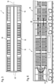
- FIGS 1-3 show different views of a sleeper transport vehicle 1, which can be moved on a track 2.
- the sleeper transport vehicle 1 comprises a wagon frame 4 supported on bogies 3, on which lateral uprights 5 and transverse and longitudinal beams 6 connected to them are arranged.
- a lower supporting loading level 7 and an upper supporting loading level 8 are formed.
- pallets are 9 in Displaceable in the longitudinal direction of the sleeper transport vehicle 1 along a guide 10 by means of a sliding device 11 .
- Each pallet 9 comprises a carrier frame 12 which is supported on longitudinal supports 13.
- the longitudinal supports 13 are advantageously designed like runners and lie on roller conveyors 14 of the respective loading level 7.8.
- the support frame 12 is designed to accommodate sleepers 15, 16 in several layers arranged one above the other. 1 shows a sleeper transport vehicle 1 on which seven pallets with new sleepers 15 and already one pallet with old sleepers 16 are loaded. In this exemplary loading condition, a pallet 9 with new sleepers 15 has already been passed on and the pallet 9 with old sleepers 16 has been added.
- each pallet 9 has limits 17 at the front and rear, which extend to the top layer of the sleepers 15, 16.
- the respective pallet 9 is guided in the guide 10 designed as a longitudinal profile by means of two guide rollers 18 .
- a groove is arranged in a longitudinal axis of symmetry 19 of the sleeper transport vehicle 1 in each loading plane 7 , 8 .
- cladding elements 30 are arranged on both longitudinal sides of the sleeper transport vehicle. These are in 1 and 6 not shown to show internal structure.
- each loading level 7 , 8 two chains with coupling elements 20 circulating in a horizontal plane are provided as a pushing device 11 for pushing the pallets 9 along the guide 10 .
- the chains are arranged on both sides of the axis of symmetry 19 and have opposite directions of rotation during operation.
- the respective outer chain strand is temporarily coupled to the pallets 9 located on the corresponding loading level 7, 8 and pushes them forward.
- each pallet 9 is equipped with a locking device 21 that can be released by remote control and is designed to fix the pallets 9 during transport.
- This can be designed, for example, as a locking bolt that secures the pallet 9 in question fixed.
- the two circulating chains are blocked in the longitudinal direction in order to fix all the pallets 9 in their position by means of the coupling elements 20 .
- ballast can be brought in and old ballast removed at the same time.
- the old ballast is dropped, for example, into a container wagon adjacent to the vehicle combination.
- a supply unit 23 is positioned below the carriage frame 4. This serves both to supply energy to various drives 24 for the circulating chains, the longitudinal conveyor belts 22 and, if necessary, for a bogie 3 designed as a motor bogie.
- the drives 24 are designed, for example, as hydraulic drives, with the supply unit 23 comprising a motor and hydraulic pumps.
- electric drives 24 are provided.
- the supply unit 23 comprises an internal combustion engine/generator unit and optionally an accumulator for temporarily storing electrical energy.
- a central control device 35 is provided in order to coordinate the individual movement sequences.
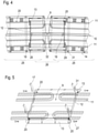
- In 4 are two loading areas 25 which are coupled to a transfer area 26 .
- the pallets 9 are transferred from one loading area 25 to the next.
- the two loading areas 25 are located on two carriage frames 4 which are articulated to one another.
- a corresponding transfer area 26 to a loading/unloading vehicle 34 is also provided at the end of the sleeper transport vehicle 1 .
- a problem-free pallet transfer is also possible during cornering if the two loading areas 25 are not aligned.
- the respective pallet 9 is continuously guided in a guide 10 with at least one guide roller 18 because the guide 10 of the respective loading area 25 protrudes into the transfer area 26 .
- the respective loading area 25 is to be regarded as the zone in which during transport to or from the construction site Pallets 9 are stored.
- the respective transfer area 26 overlaps with the end zones of the coupled loading areas 25 and is shorter in its longitudinal extent than the length of a pallet.
- the respective sliding device 11 also protrudes into the transfer area 26, so that the respective pallet 9 is continuously coupled to at least one sliding device 11 during a transfer.
- the sliding devices 11 embodied as chains
- the chain strand that is moved in a conveying direction 27 is coupled to the pallets 9 .
- the distance between the individual coupling elements 20 of the respective chain is selected in such a way that the pallets 9 are pushed on uniformly in the transfer area 26 .
- the coupling elements 20 are designed, for example, as chain link extensions which act only in the conveying direction 27 at entrainment points of the pallets 9 .
- the respective pallet 9 is first pushed from the delivering loading area 25 into the transfer area 26 by means of coupling elements 20 acting on the rear end 28 of the pallet.
- Buffer elements 31 are also usefully arranged on each pallet 9, by means of which a pallet 9 is pushed further in the conveying direction 27 by a pallet 9 that follows.
- the transport capacity of the sleeper transport vehicle 1 can be adapted to a given construction site situation by the articulated connection of several wagon frames 4 by means of a respective connecting joint 32 .
- the sleeper transport vehicle 1 can be integrated into a vehicle combination in order to cover different usage variants.
- a lifting/lowering device 33 is arranged on a rear end face of the sleeper transport vehicle 1 .
- This can be designed as a simple lifting platform.
- a loading/unloading vehicle 34 is coupled to the front end. This also includes loading levels 7, 8, via which sleepers 15, 16 are conveyed to a sleeper storage device (not shown) or from a sleeper receiving device.
- a crane-like loading/unloading device can remove new sleepers 15 from a lower pallet 9 directly in the transfer area, then place old sleepers 16 on the pallet 9 and lift the pallet 9 onto the upper loading level 8 .
- both loading levels 7, 8 of the sleeper transport vehicle 1 are loaded with new sleepers 15.
- the loading/unloading vehicle 34 removes a pallet 9 with new sleepers 15 from the lower loading level 7 . This frees up a pallet space at the rear end. A pallet 9 is lowered onto this from the upper loading level 8 by means of a lifting and lowering device 33 .
- pallets 9 are pushed backwards on the upper loading level 8 and in the transfer area 26 a pallet 9 equipped with old sleepers 16 is transferred from the loading/unloading vehicle 34 to the sleeper transport vehicle 1.
- the work cycle is repeated until both loading levels 7, 8 are fully loaded with old sleepers 16. If necessary, the conveying direction 27 can also be reversed, so that new sleepers 15 are transferred from the upper loading level 8 to the loading/unloading vehicle 34 .
- Movements of the pallets 9 are recorded by sensors and are fed to the central control device 35 .
- the control device 35 is set up for automated coordination of the individual movement sequences. During a work assignment, a continuous forward drive takes place, which is coordinated with the working speed of the sleeper depositing device or the sleeper receiving device. In this way, I move the sleeper transport vehicle 1 in association with a laying train along the track 2.
- the sleeper transport vehicle 1 Before starting work, the sleeper transport vehicle 1 is loaded at a storage location with pallets 9 that are fitted with new sleepers 15 . This process is also carried out according to the rotation principle described, using a lifting and lowering device 33 at the front. An unloading process takes place in a corresponding manner after the old sleepers 15 have been transported away. A sleeper transport vehicle 1 combined unloading of old sleepers 15 and loading of new sleepers 16 can also be useful at the storage location if several work assignments take place in a row.
- the sleeper transport vehicle 1 does not include a lifting and lowering device 33. Then only one loading level 7, 8 is loaded with pallets 9, which are equipped with new sleepers 15, before work begins. In the course of the assembly line unloading of the new sleepers 15 on the construction site, the other loading level 8, 7 is loaded with old sleepers 16. This is followed by transport to a storage location where the old sleepers 16 are unloaded.
- the sleeper transport vehicle 1 can be composed of several vehicle units, each with its own traction drive 24 .
- a connecting link 32 for the transmission of tractive forces can be omitted between such vehicle units.
- This increases flexibility in material logistics. Only during a pallet transport in the loading levels 7, 8 are the vehicle units lined up and drive together in the working direction. The vehicle units are coordinated with one another via radio links. Otherwise, the vehicle units can be moved separately. move at the same speed. As soon as a sleeper transport vehicle 1 is fully loaded with old sleepers 16, this could automatically be removed from the vehicle network and exchanged for a sleeper transport vehicle 1 loaded with new sleepers 15. In the case of automation, this would result in greater flexibility and coupling would only be necessary for a transfer journey or transport journey.
Description
Die Erfindung betrifft ein Schwellentransportfahrzeug, umfassend einen Ladebereich, der eine untere tragende Ladeebene und eine obere tragende Ladeebene aufweist, wobei in jeder Ladeebene eine Führung angeordnet ist, in der Paletten in Längsrichtung des Schwellentransportfahrzeugs geführt sind, wobei an einer Stirnseite ein Übergabebereich angeordnet ist, in welchen die Führungen hineinragen, um in einem Arbeitseinsatz Paletten mit neuen Schwellen in einer Ladeebene an ein stirnseitig angeordnetes weiteres Schwellentransportfahrzeug oder Belade-/Entladefahrzeug weiterzugeben sowie Paletten mit alten Schwellen in der anderen Ladeebene aufzunehmen. Außerdem betrifft die Erfindung ein Verfahren zur Bereitstellung neuer Schellen bzw. zur Aufnahme alter Schwellen mittels eines Schwellentransportfahrzeugs.The invention relates to a sleeper transport vehicle, comprising a loading area which has a lower load-bearing loading level and an upper load-bearing loading level, with a guide being arranged in each loading level, in which pallets are guided in the longitudinal direction of the sleeper transport vehicle, with a transfer area being arranged on a front side, into which the guides protrude in order to pass on pallets with new sleepers in one loading level to another sleeper transport vehicle or loading/unloading vehicle arranged at the front and to record pallets with old sleepers in the other loading level. The invention also relates to a method for providing new clamps or for picking up old sleepers by means of a sleeper transport vehicle.
Aktuell werden Verlegezüge für einen Schwellenaustausch über Schwellenwagons mit Neuschwellen versorgt. Seitlich sind an den Schwellenwagons Kranschienen angeordnet, auf denen ein Portalkran verfährt. Zwischen den Schwellenwagons werden Verbindungsstücke benötigt, um ein Verfahren von einem Wagon auf den nächsten zu ermöglichen. Durch die Verbindungsstücke wird nicht nur die Bewegungsfreiheit in einer Kurve stark eingeschränkt, auch ein Bediener für den Portalkran wird benötigt. Eine Automatisierung ist hier nur schwer realisierbar. Außerdem entsteht bei einem Einsatz mehrerer Portalkräne ein hohes Kollisionsrisiko welchem entgegen gewirkt werden muss.Laying trains for a sleeper replacement are currently being supplied with new sleepers via sleeper wagons. Crane rails on which a gantry crane moves are arranged on the sides of the sleeper wagons. Connectors are required between the sleeper wagons to enable movement from one wagon to the next. The connecting pieces not only severely restrict the freedom of movement in a curve, they also require an operator for the gantry crane. Automation is difficult to implement here. In addition, when several gantry cranes are used, there is a high risk of collision, which must be counteracted.
Aus der
Die
Der Erfindung liegt die Aufgabe zugrunde, für ein Schwellentransportfahrzeug der eingangs genannten Art eine Verbesserung gegenüber dem Stand der Technik anzugeben. Zudem betrifft die Erfindung ein Verfahren zum Betreiben eines Schwellentransportfahrzeugs.The invention is based on the object of specifying an improvement over the prior art for a sleeper transport vehicle of the type mentioned at the outset. In addition, the invention relates to a method for operating a sleeper transport vehicle.
Bezüglich der Vorrichtung wird die gestellte Aufgabe erfindungsgemäß durch die Merkmalskombination gemäß Anspruch 1 gelöst. Die auf ein Verfahren gerichtete Aufgabe wird erfindungsgemäß durch die Merkmalskombination gemäß Anspruch 12 gelöst. Abhängige Ansprüche geben vorteilhafte Ausgestaltungen der Erfindung an.With regard to the device, the stated object is achieved according to the invention by the combination of features according to claim 1 . The object directed to a method is achieved according to the invention by the combination of features according to
Die Erfindung sieht vor, dass in jeder Ladeebene eine Schiebeeinrichtung zum Schieben der Paletten entlang der Führungen angeordnet ist. Die jeweilige Schiebeeinrichtung ist als zumindest eine in den Übergabebereich hineinragende, umlaufende Kette ausgebildet, wobei an den Paletten Koppelelemente zur vorübergehenden Kopplung mit der Kette angeordnet sind. Die umlaufende Kette stellt eine zuverlässige Lösung für ein Verschieben der Paletten auf einer der Ladeebene dar. Die Koppelelemente werden einfach in einem benötigten Abstand an der Kette positioniert.The invention provides that a sliding device for sliding the pallets along the guides is arranged in each loading level. The respective sliding device is designed as at least one circulating chain that projects into the transfer area, with coupling elements being arranged on the pallets for temporary coupling to the chain. The circulating chain represents a reliable solution for shifting the pallets on one of the loading levels. The coupling elements are simply positioned on the chain at a required distance.
Zudem ist es sinnvoll, wenn in jeder Ladeebene beidseits einer längsverlaufenden Symmetrieachse jeweils eine umlaufende Kette angeordnet ist. Durch einen Einsatz von zwei umlaufenden Ketten pro Ladeebene wird eine auf die Paletten wirkende Verschiebekraft gleichmäßig aufgeteilt. Durch ein beidseitiges Verschieben wird einem Verkeilen der Paletten in den Führungen entgegen gewirkt.In addition, it makes sense if a revolving chain is arranged in each loading plane on both sides of a longitudinal axis of symmetry. By using two circulating chains per loading level, a shifting force acting on the pallets becomes even divided up. Moving on both sides counteracts the pallets becoming wedged in the guides.
In einer vorteilhaften Ausprägung ist die jeweilige Führung als Längsprofil ausgebildet und an den Paletten sind Führungsrollen zur Führung entlang des Längsprofils angeordnet. Durch ein Abrollen der Paletten über die Führungsrollen in den Längsprofilen ist eine reibungsarme Führung der Palette gewährleistet.In an advantageous embodiment, the respective guide is designed as a longitudinal profile and guide rollers are arranged on the pallets for guiding along the longitudinal profile. Low-friction pallet guidance is ensured by rolling the pallets over the guide rollers in the longitudinal profiles.
Für ein reibungsarmes Verschieben der Paletten ist es vorteilhaft, wenn jede Palette an ihrer Unterseite Längsauflagen zum Aufliegen auf einem Rollengang umfasst. Dabei sind die Paletten sehr robust und einfach aufgebaut. Zudem sind sie wartungsfrei, weil alle beweglichen Teile (Lager, Rollen) am Fahrzeug angeordnet sind.For low-friction shifting of the pallets, it is advantageous if each pallet has longitudinal supports on its underside for resting on a roller conveyor. The pallets are very robust and simply constructed. In addition, they are maintenance-free because all moving parts (bearings, rollers) are located on the vehicle.
Dabei ist es günstig, wenn in jeder Ladeebene eine mittig verlaufende Führung und beidseits dieser Führung jeweils ein Rollengang angeordnet sind. Durch die mittig verlaufende Führung wird die jeweilige Palette präzise auf der Symmetrieachse der Ladeebene geführt und die Gewichtsbelastung teilt sich gleichmäßig auf beide Rollengänge auf.It is favorable if a centrally running guide and a roller conveyor are arranged on each side of this guide in each loading plane. Due to the centrally running guide, the respective pallet is guided precisely on the symmetry axis of the loading level and the weight load is shared equally between the two roller conveyors.
Vorteilhafterweise ist jeder Palette eine Verriegelungseinrichtung zur vorübergehenden Fixierung während einer Transportfahrt zugeordnet. Dadurch werden die Paletten samt den Schwellen bei Fahrten zu bzw. von einer Baustelle sicher in Position gehalten.Advantageously, each pallet is assigned a locking device for temporary fixation during transport. This keeps the pallets and sleepers securely in place when driving to and from a construction site.
Bei einer weiteren günstigen Ausgestaltung der Erfindung umfasst das Transportfahrzeug einen Wagenrahmen, der auf Drehgestellen abgestützt ist, wobei zumindest ein Drehgestell als Triebdrehgestell ausgebildet ist. Dadurch wird ein selbständiges Verfahren des Transportfahrzeuges erreicht was sich vorteilhaft auf eine Automatisierung des Arbeitseinsatzes auswirkt.In a further advantageous embodiment of the invention, the transport vehicle comprises a wagon frame which is supported on bogies, with at least one bogie being designed as a powered bogie. As a result, the transport vehicle moves independently, which has an advantageous effect on the automation of the work assignment.
Zudem ist es sinnvoll, wenn das Transportfahrzeug an beiden Längsseiten Verkleidungselemente aufweist. Sollten die Schwellen innerhalb der Palette seitlich verrutschen werden diese trotzdem sicher innerhalb des Schwellentransportfahrzeuges und somit im Lichtraumprofil gehalten.In addition, it makes sense if the transport vehicle has cladding elements on both longitudinal sides. If the sleepers slip sideways within the pallet, they are still held securely within the sleeper transport vehicle and thus within the clearance profile.
Eine vorteilhafte Weiterbildung der Erfindung sieht vor, dass das Transportfahrzeug oberhalb der oberen Ladeebene eine tragende Förderebene aufweist, in der zumindest ein Längsförderband zum Transport von Schüttgut angeordnet ist. Dadurch kann zusätzlich bei einem Schwellenaustausch auch Schüttgut zu- bzw. abgeführt werden.An advantageous development of the invention provides that the transport vehicle has a supporting conveyor level above the upper loading level, in which at least one longitudinal conveyor belt for transport of bulk material is arranged. This means that bulk material can also be fed in or removed when the sleeper is replaced.
In einer vorteilhaften Ausprägung ist an der dem Übergabebereich gegenüberliegenden Stirnseite eine Hebe-/Senkvorrichtung zum Heben bzw. Senken einer Palette von einer Ladeebene in die andere Ladeebene angeordnet. Dadurch wird beim Entladen von Neuschwellen bzw. beim Beladen mit Altschwellen ein Weitertransport der Paletten über beide Ladeebenen hinweg ermöglicht. Auf diese Weise sind beide Ladeebenen für eine Neuschwellenanlieferung bzw. einen Altschwellenabtransport nutzbar.In an advantageous embodiment, a lifting/lowering device for lifting or lowering a pallet from one loading level to the other loading level is arranged on the end face opposite the transfer area. This enables the pallets to be transported further across both loading levels when unloading new sleepers or loading old sleepers. In this way, both loading levels can be used for the delivery of new sleepers or the removal of old sleepers.
Eine weitere Steigerung der Ladekapazität wird vorteilhafterweise dadurch erreicht, dass das Transportfahrzeug wenigstens zwei Wagenrahmen umfasst, die gelenkig miteinander verbunden sind, dass jedem Wagenrahmen ein eigener Ladebereich zugeordnet ist und dass die Ladebereiche mit einem Übergabebereich gekoppelt sind, in welchen die jeweiligen Führungen und die jeweiligen Schiebeeinrichtungen hineinragen, um die Paletten über beide Ladebereiche hinweg in Längsrichtung weiterzuschieben. Durch eine solche gelenkige Aneinanderreihung mehrerer Wagenrahmen kann die Ladekapazität flexibel angepasst werden. Die maximale Länge der Wagenrahmen ist dabei durch einen durchfahrbaren Mindestgleisradius und ein einzuhaltendes Lichtraumprofil vorgegebenen.A further increase in the loading capacity is advantageously achieved in that the transport vehicle comprises at least two wagon frames which are articulated to one another, that each wagon frame is assigned its own loading area and that the loading areas are coupled to a transfer area, in which the respective guides and the respective Sliding devices protrude to move the pallets lengthwise across both loading areas. The loading capacity can be flexibly adjusted by such an articulated arrangement of several wagon frames. The maximum length of the wagon frame is specified by a minimum track radius that can be driven through and a clearance profile that must be observed.
Das erfindungsgemäße Verfahren zur Bereitstellung neuer Schellen bzw. zur Aufnahme alter Schwellen mittels eines Schwellentransportfahrzeugs sieht vor, dass im Übergabebereich die in der einen Ladeebene weitergeschobenen Paletten mit neuen Schwellen vom Schwellentransportfahrzeug an das Belade-/Entladefahrzeug übergeben werden und dass in der anderen Ladeebene Paletten mit alten Schwellen vom Belade-/Entladefahrzeug an das Schwellentransportfahrzeug übergeben werden. Auf diese Weise erfolgt eine fließbandmäßige Versorgung mit Neuschwellen bzw. ein ebensolcher Abtransport von Altschwellen.The method according to the invention for providing new clamps or for picking up old sleepers by means of a sleeper transport vehicle provides that in the transfer area the pallets with new sleepers that have been pushed further in one loading level are transferred from the sleeper transport vehicle to the loading/unloading vehicle and that in the other loading level pallets with old sleepers are transferred from the loading/unloading vehicle to the sleeper transport vehicle. In this way, an assembly line supply of new sleepers and a similar removal of old sleepers takes place.
In einer günstigen Weiterbildung des Verfahrens werden mittels einer an der dem Übergabebereich gegenüberliegenden Stirnseite angeordneten Hebe-/Senkvorrichtung Paletten von einer Ladeebene in die andere Ladeebene gehoben bzw. abgesenkt. Damit werden beide Ladeebenen in eine rotationsmäßige Versorgung mit Neuschwellen bzw. Aufnahme von Altschwellen einbezogen. Die Paletten bewegen sich dabei auf den Ladeebene in entgegengesetzten Richtungen, wobei mittels der Hebe-/Senkvorrichtung eine Weitergabe zwischen den Ladeebenen erfolgt.In a favorable further development of the method, pallets are raised or lowered from one loading level to the other loading level by means of a lifting/lowering device arranged on the end face opposite the transfer area. This turns both loading levels into one rotational supply of new sleepers and inclusion of old sleepers included. The pallets move in opposite directions on the loading level, with the lifting/lowering device being used to transfer them between the loading levels.
Dabei ist es sinnvoll wenn das Schwellentransportfahrzeug während einer Palettenübergabe gemeinsam mit dem Belade-/Entladefahrzeug mit einer vorgegebenen Arbeitsgeschwindigkeit entlang eines Gleises bewegt wird, dessen Schwellen mittels einer Schellentauschvorrichtung getauscht werden. Auf diese Weise erfolgt ein kontinuierlicher Schwellenaustausch, bei dem ein Verlegezug mit gleichmäßiger Geschwindigkeit vorwärts fährt. Ein derartiger Schwellentausch im kontinuierlichen Fließbandverfahren ist besonders effektiv und kostensparend.It makes sense if the sleeper transport vehicle is moved during a pallet transfer together with the loading/unloading vehicle at a predetermined working speed along a track whose sleepers are exchanged by means of a clamp exchange device. In this way, a continuous exchange of sleepers takes place, with a laying train driving forward at a constant speed. Such a sleeper replacement in a continuous assembly line process is particularly effective and cost-saving.
Die Erfindung wird nachfolgend in beispielhafter Weise unter Bezugnahme auf die beigefügten Figuren erläutert. Es zeigen in schematischer Darstellung:
- Fig. 1
- Seitenansicht eines Schwellentransportfahrzeugs
- Fig. 2
- Vorderansicht eines Schwellentransportfahrzeug
- Fig. 3
- Draufsicht eines Schwellentransportfahrzeug
- Fig. 4
- Draufsicht auf einen Übergabebereich
- Fig. 5
- Vereinfachte Schrägansicht eines Übergabebereichs
- Fig. 6
- Schwellentransportfahrzeug mit Hebe-/Senkvorrichtung
- 1
- Side view of a sleeper transport vehicle
- 2
- Front view of a sleeper transport vehicle
- 3
- Top view of a sleeper transport vehicle
- 4
- Top view of a transfer area
- figure 5
- Simplified oblique view of a transfer area
- 6
- Sleeper transport vehicle with lifting/lowering device
Die
Jede Palette 9 umfasst einen Trägerrahmen 12, welcher auf Längsauflagen 13 abgestützt ist. Die Längsauflagen 13 sind vorteilhafterweise kufenartig ausgebildet und liegen auf Rollengängen 14 der jeweiligen Ladeebene 7,8 auf. Der Trägerrahmen 12 ist zur Aufnahme von Schwellen 15,16 in mehreren übereinander angeordneten Lagen ausgebildet.
Um ein Verrutschen der Schwellen 15, 16 in Fahrtrichtung zu verhindern, umfasst jede Palette 9 vorne und hinten Begrenzungen 17, die bis zur obersten Lage der Schwellen 15, 16 reichen. Mittels zweier Führungsrollen 18 ist die jeweiligen Palette 9 in der als Längsprofil ausgebildeten Führung 10 geführt. Konkret ist in jeder Ladeebene 7, 8 eine Nut in einer längsverlaufenden Symmetrieachse 19 des Schwellentransportfahrzeugs 1 angeordnet. Um ein seitliches Verschieben von Schwellen 15, 16 zu verhindern, sind an beiden Längsseiten des Schwellentransportfahrzeugs 1 Verkleidungselemente 30 angeordnet. Diese sind in
In jeder Ladeebene 7, 8 sind als Schiebeeinrichtung 11 zum Schieben der Paletten 9 entlang der Führung 10 zwei in einer horizontalen Ebene umlaufende Ketten mit Koppelelementen 20 vorgesehen. Die Ketten sind beidseits der Symmetrieachse 19 angeordnet und weisen im Betrieb eine gegengleiche Umlaufrichtung auf. Der jeweils äußere Kettenstrang ist dabei vorübergehend mit den auf der entsprechenden Ladeebene 7, 8 befindlichen Paletten 9 gekoppelt und schiebt diese vorwärts.In each
Zusätzlich ist jede Palette 9 mit einer ferngesteuert lösbaren Verriegelungsvorrichtung 21 ausgestattet, welche zur Fixierung der Paletten 9 während einer Transportfahrt ausgelegt ist. Diese kann beispielhaft als Verriegelungsbolzen ausgebildet sein, der die jeweilige Palette 9 sicher fixiert. In einer anderen Variante werden die zwei umlaufenden Ketten in Längsrichtung blockiert, um alle Paletten 9 mittels der Koppelelemente 20 in ihrer Position zu fixieren.In addition, each
Oberhalb der oberen Ladeebene 8 befinden sich zusätzlich zwei Längsförderbänder 22 zum Transport von Schüttgut. Somit können ein gleichzeitiges Zubringen von Neuschotter und ein Abtransport von Altschotter erfolgen. Der Altschotter wird beispielsweise in einen an den Fahrzeugverbund angrenzenden Containerwagen abgeworfen.Above the
Unterhalb des Wagenrahmens 4 ist eine Versorgungseinheit 23 positioniert. Diese dient sowohl zur Energieversorgung diverser Antriebe 24 für die umlaufenden Ketten, die Längsförderbänder 22 und gegebenenfalls für ein als Triebdrehgestell ausgebildetes Drehgestell 3. Die Antriebe 24 sind zum Beispiel als Hydraulikantriebe ausgebildet, wobei die Versorgungseinheit 23 einen Motor und Hydraulikpumpen umfasst. Alternativ dazu sind elektrische Antriebe 24 vorgesehen. Die Versorgungseinheit 23 umfasst dabei eine Verbrennungsmotor-Generator-Einheit und gegebenenfalls einen Akkumulator zur Zwischenspeicherung elektrischer Energie. Zudem ist eine zentrale Steuerungseinrichtung 35 vorgesehen, um die einzelnen Bewegungsabläufe zu koordinieren.Below the
In
Die jeweilige Palette 9 wird während der Übergabe durchgehend mit zumindest einer Führungsrolle 18 in einer Führung 10 geführt, weil die Führung 10 des jeweiligen Ladebereichs 25 in den Übergabebereich 26 hineinragen. Der jeweilige Ladebereich 25 ist dabei als jene Zone anzusehen, in der während eines Transports zur oder von der Baustelle Paletten 9 gelagert sind. Der jeweilige Übergabebereich 26 überschneidet sich mit Endzonen der gekoppelten Ladebereiche 25 und ist in seiner Längsausdehnung kürzer als eine Palettenlänge.During the transfer, the
Auch die jeweilige Schiebeeinrichtung 11 ragt in den Übergabebereich 26, sodass die jeweilige Palette 9 während einer Übergabe durchgehend mit zumindest einer Schiebeeinrichtung 11 gekoppelt ist. Konkret ist bei den beispielhaft als Ketten ausgebildeten Schiebeeinrichtungen 11 der jeweils in einer Förderrichtung 27 bewegte Kettenstrang mit den Paletten 9 gekoppelt. Dabei ist der Abstand zwischen den einzelnen Koppelelementen 20 der jeweiligen Kette so gewählt, dass im Übergabebereich 26 ein gleichmäßiges Weiterschieben der Paletten 9 erfolgt. Ausgebildet sind die Koppelelemente 20 beispielsweise als Kettengliedfortsätze, die lediglich in Förderrichtung 27 an Mitnahmestellen der Paletten 9 angreifen. Dabei wird die jeweilige Palette 9 zunächst vom abgebenden Ladebereich 25 mittels am hinteren Palettenende 28 angreifenden Koppelelementen 20 in den Übergabebereich 26 geschoben. In weiterer Folge wird die Palette 9 mit am vorderen Palettenende angreifenden Koppelelementen 20 in den aufnehmenden Ladebereich 25 gezogen. Sinnvollerweise sind zusätzlich an jeder Palette 9 Pufferelemente 31 angeordnet, mittels derer eine Palette 9 von einer nachgereihten Palette 9 in Förderrichtung 27 weitergeschoben wird.The respective sliding
Durch die gelenkige Verbindung mehrerer Wagenrahmen 4 mittels eines jeweiligen Verbindungsgelenks 32 ist die Transportkapazität des Schwellentransportfahrzeugs 1 an eine vorliegende Baustellensituation anpassbar. Dabei ist das Schwellentransportfahrzeug 1 in einen Fahrzeugverbund integrierbar, um unterschiedliche Nutzungsvarianten abzudecken.The transport capacity of the sleeper transport vehicle 1 can be adapted to a given construction site situation by the articulated connection of
Ein vorteilhaftes Verfahren wird mit Bezug auf
Zu Arbeitsbeginn sind beide Ladeebenen 7, 8 des Schwellentransportfahrzeugs 1 mit Neuschwellen 15 beladen. Das Belade-/Entladefahrzeug 34 entnimmt eine Palette 9 mit Neuschwellen 15 aus der unteren Ladeebene 7. Dabei schiebt die Schiebeeinrichtung 11 der unteren Ladeebene 7 Paletten 9 in Förderrichtung 27 nach. An der hinteren Stirnseite wird dadurch ein Palettenplatz frei. Auf diesen wird aus der oberen Ladeebene 8 eine Palette 9 mittels Hebe- und Senkvorrichtung 33 abgesenkt.At the start of work, both
Im selben Arbeitszyklus werden Paletten 9 in der oberen Ladeebene 8 nach hinten geschoben und im Übergabebereich 26 erfolgt eine Übergabe einer mit Altschwellen 16 bestückten Palette 9 vom Belade-/Entladefahrzeug 34 auf das Schwellentransportfahrzeug 1. Der Arbeitszyklus wird wiederholt, bis beide Ladeebenen 7, 8 vollständig mit Altschwellen 16 beladen sind. Dabei kann bei Bedarf die Förderrichtung 27 auch umgekehrt sein, sodass Neuschwellen 15 von der oberen Ladeebene 8 auf das Belade-/Entladefahrzeug 34 übergeben werden.In the same work cycle,
Über Sensoren werden Bewegungen der Paletten 9 erfasst und an der zentralen Steuerungseinrichtung 35 zugeführt. Die Steuerungseinrichtung 35 ist dabei zur automatisierten Koordination der einzelnen Bewegungsabläufe eingerichtet. Während eines Arbeitseinsatzes erfolgt eine kontinuierliche Vorwärtsfahrt, die auf die Arbeitsgeschwindigkeit der Schwellenablagevorrichtung bzw. der Schwellenaufnahmevorrichtung abgestimmt ist. Auf diese Weise bewegt ich das Schwellentransportfahrzeug 1 im Verband mit einem Verlegezug entlang des Gleises 2.Movements of the
Vor einem Arbeitseinsatz wird das Schwellentransportfahrzeug 1 an einem Lagerort mit Paletten 9 beladen, die mit neuen Schwellen 15 bestückt sind. Auch dieser Vorgang erfolgt sinnvollerweise nach dem beschriebenen Rotationsprinzip unter Verwendung einer stirnseitigen Hebe- und Senkvorrichtung 33. In entsprechender Weise erfolgt ein Entladevorgang nach einem Abtransport der alten Schwellen 15. Auch am Lagerort kann eine Schwellentransportfahrzeug 1 kombinierte Entladung von Altschwellen 15 und Beladung von Neuschwellen 16 sinnvoll sein, wenn mehrere Arbeitseinsätze hintereinander erfolgen.Before starting work, the sleeper transport vehicle 1 is loaded at a storage location with
In einer einfachen Variante umfasst das Schwellentransportfahrzeug 1 keine Hebe- und Senkvorrichtung 33. Dann ist vor einem Arbeitseinsatz nur eine Ladeebene 7, 8 mit Paletten 9 beladen, die mit Neuschwellen 15 bestückt sind. Im Zuge des fließbandmäßigen Entladens der Neuschwellen 15 auf der Baustelle wird die andere Ladeebene 8, 7 mit Altschwellen 16 beladen. Anschließend erfolgt ein Transport zu einem Lagerort, wo die Altschwellen 16 abgeladen werden.In a simple variant, the sleeper transport vehicle 1 does not include a lifting and lowering
In einer weiteren Variante kann das Schwellentransportfahrzeug 1 aus mehreren Fahrzeugeinheiten mit jeweils eigenem Fahrantrieb 24 zusammengesetzt sein. Zwischen solchen Fahrzeugeinheit kann ein Verbindungsgelenkt 32 zur Übertragung von Zugkräften entfallen. Das erhöht die Flexibilität bei der Materiallogistik. Lediglich während einer Palettenbeförderung in den Ladeebenen 7, 8 sind die Fahrzeugeinheiten aneinandergereiht und fahren gemeinsam in Arbeitsrichtung. Dabei sind die Fahrzeugeinheiten über Funkverbindungen aufeinander abgestimmt. Ansonsten sind die Fahrzeugeinheiten separat verfahrbar. in gleicher Geschwindigkeit verfahren lassen. Sobald ein Schwellentransportfahrzeug 1 mit Altschwellen 16 voll beladen ist, könnte dies sich automatisch aus dem Fahrzeugverbund entfernen und gegen ein mit Neuschwellen 15 beladenes Schwellentransportfahrzeug 1 ausgetauscht werden. Dies hätte bei einer Automatisierung eine größere Flexibilität zur Folge und ein Kuppeln wäre nur bei einer Überstellfahrt bzw. Transportfahrt notwendig.In a further variant, the sleeper transport vehicle 1 can be composed of several vehicle units, each with its
Claims (14)
- A sleeper transport vehicle (1) having a loading area (25) which includes a lower supporting loading plane (7) and an upper supporting loading plane (8), wherein in each loading plane (7,8) a guide (10) is arranged in which pallets (9) are guided in the longitudinal direction of the sleeper transport vehicle (1), wherein, at a front side, a transfer area (26) is arranged into which the guides (10) protrude in order to pass along during a working operation pallets (9) with new sleepers (15) in one loading plane (7,8) to a further sleeper transport vehicle (1) or loading/unloading vehicle (34) arranged at the front side, and to receive pallets with old sleepers (16) in the other loading plane (7,8), characterized in that in each loading plane (7,8) a pushing device (11) for pushing the pallets (9) along the guide (10) is designed as at least one circulating chain protruding into the transfer area, and that coupling elements (20) are arranged on the pallets (9) for temporary coupling to the chain.
- A sleeper transport vehicle (1) according to claim 1, characterized in that in each loading plane (7,8) a respective circulating chain is arranged at both sides of a longitudinally extending axis of symmetry (19).
- A sleeper transport vehicle (1) according to claim 1 or 2, characterized in that the respective guide (10) is designed as a longitudinal profile, and that guide rollers (18) for guiding along the longitudinal profile are arranged on the pallets (9).
- A sleeper transport vehicle (1) according to one of claims 1 to 3, characterized in that each pallet (9) has at its underside longitudinal supports (13) for placement on a rollerway (14).
- A sleeper transport vehicle (1) according to claim 4, characterized in that a centrally extending guide (10) and, at either side of said guide (10), a respective rollerway (14) are arranged in each loading plane (7,8).
- A sleeper transport vehicle (1) according to one of claims 1 to 5, characterized in that a locking device (21) for temporary fixation during transport travel is associated with each pallet (9).
- A sleeper transport vehicle (1) according to one of claims 1 to 6, characterized in that the transport vehicle (1) comprises a wagon frame (4) which is supported on bogies (3), and that at least one bogie (3) is configured as a motor bogie.
- A sleeper transport vehicle (1) according to one of claims 1 to 7, characterized in that the transport vehicle (1) has panelling elements (30) at both longitudinal sides.
- A sleeper transport vehicle (1) according to one of claims 1 to 8, characterized in that, above the upper loading plane (8), the transport vehicle (1) has a supporting conveying plane in which at least one longitudinal conveyor belt (22) for transport of bulk material is arranged.
- A sleeper transport vehicle (1) according to one of claims 1 to 9, characterized in that a lifting/lowering device (33) for lifting or lowering a pallet (9) from one loading plane (7,8) to the other loading plane (7,8) is arranged at the front side lying opposite to the transfer area (26).
- A sleeper transport vehicle (1) according to one of claims 1 to 10, characterized in that the transport vehicle (1) comprises at least two wagon frames (4) which are articulatedly connected to one another, that a separate loading area (25) is associated with each wagon frame (4), and that the loading areas (25) are coupled to a transfer area (26) into which the respective guides (10) and the respective pushing devices (11) protrude in order to push the pallets (9) onward in the longitudinal direction across both loading areas (25).
- A method for supplying new sleepers (15) or for taking up old sleepers (16) by means of a sleeper transport vehicle (1) according to one of claims 1 to 11, characterized in that the pallets (9) with new sleepers (15), which have been pushed onward in the one loading area (7,8), are passed from the sleeper transport vehicle (1) to the loading/unloading vehicle in the transfer area (26), and that in the other loading plane (7,8) pallets (9) with old sleepers (16) are passed from the loading/unloading vehicle (34) to the sleeper transport vehicle (1).
- A method according to claim 12, characterized in that pallets (9) are lifted or lowered from one loading plane (7,8) to the other loading plane (7,8) by means of a lifting/lowering device arranged at the front side lying opposite the transfer area (26).
- A method according to claim 12 or 13, characterized in that, during a pallet transfer, the sleeper transport vehicle (1) is moved together with the loading/unloading vehicle (34) with a pre-set working speed along a track (2), the sleepers (15,16) of which are exchanged by means of a sleeper changing device.
Applications Claiming Priority (2)
| Application Number | Priority Date | Filing Date | Title |
|---|---|---|---|
| AT5012017 | 2017-12-28 | ||
| PCT/EP2018/086467 WO2019129678A1 (en) | 2017-12-28 | 2018-12-21 | Sleeper transport vehicle |
Publications (2)
| Publication Number | Publication Date |
|---|---|
| EP3732330A1 EP3732330A1 (en) | 2020-11-04 |
| EP3732330B1 true EP3732330B1 (en) | 2022-01-26 |
Family
ID=65011985
Family Applications (1)
| Application Number | Title | Priority Date | Filing Date |
|---|---|---|---|
| EP18833231.6A Active EP3732330B1 (en) | 2017-12-28 | 2018-12-21 | Sleeper transport vehicle |
Country Status (4)
| Country | Link |
|---|---|
| US (1) | US11541916B2 (en) |
| EP (1) | EP3732330B1 (en) |
| CN (1) | CN111492109A (en) |
| WO (1) | WO2019129678A1 (en) |
Families Citing this family (4)
| Publication number | Priority date | Publication date | Assignee | Title |
|---|---|---|---|---|
| IT201900008283A1 (en) * | 2019-06-06 | 2020-12-06 | Srt Soc A Responsabilita Limitata Con Unico Socio | RAILWAY WAGON FOR HANDLING SLEEPERS, RAILWAY VEHICLE INCLUDING SAID WAGON |
| US11225758B1 (en) * | 2019-06-26 | 2022-01-18 | Union Pacific Railroad Company | Automated railroad tie unloading |
| FR3109129B1 (en) | 2020-04-11 | 2022-08-12 | Matisa Materiel Ind Sa | mechanism for moving back and forth stacks of sleepers and railway vehicle comprising such a mechanism |
| FR3109128B1 (en) | 2020-04-11 | 2022-08-12 | Matisa Materiel Ind Sa | Sleeper transfer wagon and associated rail vehicle |
Family Cites Families (14)
| Publication number | Priority date | Publication date | Assignee | Title |
|---|---|---|---|---|
| IT219394Z2 (en) * | 1990-03-13 | 1993-02-26 | INDEPENDENT WHEEL MOTORIZED TROLLEY FOR LOWERED VEHICLES | |
| US5549050A (en) * | 1995-06-08 | 1996-08-27 | Rhodes; Arthur B. | Load carrying unit for a conveyor system |
| US6250457B1 (en) * | 1999-12-09 | 2001-06-26 | Webster Industries, Inc. | Engineering class steel conveyor chain |
| US20030228208A1 (en) * | 2000-05-25 | 2003-12-11 | Grond Johann W. | Vertical conveyor and vertical conveyor system |
| DE60133078T2 (en) * | 2000-06-06 | 2009-02-26 | Mitsubishi Heavy Industries, Ltd. | PLANE WITH A MULTIPLE OF UPPER AND LOWER CABINS OPERATING AS PASSENGER CABINS OR FREIGHT DEPARTMENTS AND METHOD FOR LOADING FREIGHT TO A PLANE |
| JP3854853B2 (en) * | 2001-11-14 | 2006-12-06 | 東海旅客鉄道株式会社 | Sleeper carrier |
| US7559738B2 (en) * | 2004-02-09 | 2009-07-14 | Winkler + Dünnebier Aktiengesellschaft | Device and a method for switching pallets |
| KR101127002B1 (en) * | 2006-11-16 | 2012-06-14 | 미츠비시 쥬고교 가부시키가이샤 | Truck structure of track-type vehicle |
| RU2377355C1 (en) * | 2008-05-21 | 2009-12-27 | Федеральное государственное унитарное предприятие Научно-внедренческий центр "Путевые машины" Федерального агентства железнодорожного транспорта | Mobile device for single replacement of ties on stand in repair of rail lengths |
| FR2931777B1 (en) * | 2008-05-30 | 2014-03-21 | Europ De Travaux Ferroviaires Etf | TRAILER RAIL OF TRAILERS WITH SLIDING DECK |
| DE102010032268A1 (en) * | 2010-07-26 | 2012-01-26 | Eiffage Rail Gmbh | transport platform |
| CN102002896B (en) * | 2010-12-14 | 2012-11-21 | 无锡盾建重工制造有限公司 | CRTS III ballastless track slab layering fine tuning vehicle |
| DK2709893T3 (en) * | 2011-05-16 | 2020-07-13 | K&K Maschinenentwicklungs Gmbh & Co Kg | SYSTEM, PROCEDURE AND RAILWAY TROLLEYS FOR RAILWAY TRANSPORT OF ITEMS |
| AT518477B1 (en) * | 2016-04-05 | 2018-10-15 | Plasser & Theurer Export Von Bahnbaumaschinen Gmbh | Method and transport vehicle for loading and unloading |
-
2018
- 2018-12-21 EP EP18833231.6A patent/EP3732330B1/en active Active
- 2018-12-21 CN CN201880081869.XA patent/CN111492109A/en active Pending
- 2018-12-21 WO PCT/EP2018/086467 patent/WO2019129678A1/en unknown
- 2018-12-21 US US16/771,871 patent/US11541916B2/en active Active
Also Published As
| Publication number | Publication date |
|---|---|
| WO2019129678A1 (en) | 2019-07-04 |
| US11541916B2 (en) | 2023-01-03 |
| US20210179150A1 (en) | 2021-06-17 |
| CN111492109A (en) | 2020-08-04 |
| EP3732330A1 (en) | 2020-11-04 |
Similar Documents
| Publication | Publication Date | Title |
|---|---|---|
| EP3732330B1 (en) | Sleeper transport vehicle | |
| EP0776291B1 (en) | Process and device for transferring freight | |
| DE102015114370B4 (en) | Driverless transport system in a storage and picking system | |
| DE102009032406A1 (en) | Rack storage system has storage rack with multiple adjacent shelves between which rack crankshaft gap extends from rack storage side to another rack storage side | |
| DE102013017062A1 (en) | Feed unit and conveyor system for conveying load carriers | |
| AT501062A1 (en) | METHOD FOR PROMOTING GOODS AND PLANT FOR IMPLEMENTING THE PROCESS | |
| WO2015024624A1 (en) | Method and unit for conveying load carriers | |
| DE2113202B2 (en) | Goods stores with vertically movable transfer equipment - has self-propelling transport units on rails of individual floors of vertical shelf rows | |
| DE2713634C2 (en) | ||
| EP2602215B1 (en) | Logistics system for combined movement of goods, and railway vehicle and transfer station for the same | |
| EP1422169B1 (en) | Warehouse with rail trolleys for storing and retrieving goods | |
| EP1619146A1 (en) | Device for distributing load carriers for piece goods | |
| DE102018117844A1 (en) | Transfer station for a transport device | |
| EP1241118B1 (en) | Method and device for loading and unloading palletized bulk goods from road vehicles onto railway trains and vice versa | |
| EP1040027B1 (en) | Loading and unloading system for cargo trucks, their trailers, transport containers and the like | |
| DE202020102392U1 (en) | Rail-bound platform wagon with conveyor belt and loading area | |
| DE2839496C2 (en) | Method and device for transferring material to be conveyed from a rail-mounted driven roller conveyor to a drivable roller conveyor with frictional engagement designed as a storage area | |
| EP0599841B1 (en) | Method and device for transshipping containers | |
| DE69530937T3 (en) | METHOD AND DEVICE FOR HANDLING LEAVES | |
| DE2417733C3 (en) | System for moving loads on one level between several stations | |
| DE102010040152A1 (en) | Transferring device for conveying charge carrier from conveying belt onto trolley, has drive unit with stroke motor, that is located on the lifting unit so that lowering and lifting of the lifting elements are possible | |
| DE4213925A1 (en) | Goods waggon train for bulk goods transportation - consists of transship wagons with cantilever conveyor and movable base, and goods wagons with movable base | |
| DE2931241C2 (en) | Device for transporting loading units | |
| DE1908525A1 (en) | System or device for holding, handling, removing and distributing items of goods, in particular on pallets | |
| EP0844158B1 (en) | Installation for loading and unloading of trains |
Legal Events
| Date | Code | Title | Description |
|---|---|---|---|
| STAA | Information on the status of an ep patent application or granted ep patent |
Free format text: STATUS: UNKNOWN |
|
| STAA | Information on the status of an ep patent application or granted ep patent |
Free format text: STATUS: THE INTERNATIONAL PUBLICATION HAS BEEN MADE |
|
| PUAI | Public reference made under article 153(3) epc to a published international application that has entered the european phase |
Free format text: ORIGINAL CODE: 0009012 |
|
| STAA | Information on the status of an ep patent application or granted ep patent |
Free format text: STATUS: REQUEST FOR EXAMINATION WAS MADE |
|
| 17P | Request for examination filed |
Effective date: 20200728 |
|
| AK | Designated contracting states |
Kind code of ref document: A1 Designated state(s): AL AT BE BG CH CY CZ DE DK EE ES FI FR GB GR HR HU IE IS IT LI LT LU LV MC MK MT NL NO PL PT RO RS SE SI SK SM TR |
|
| AX | Request for extension of the european patent |
Extension state: BA ME |
|
| DAV | Request for validation of the european patent (deleted) | ||
| DAX | Request for extension of the european patent (deleted) | ||
| RIC1 | Information provided on ipc code assigned before grant |
Ipc: E01B 29/05 20060101AFI20210708BHEP Ipc: E01B 29/06 20060101ALI20210708BHEP Ipc: B61D 15/00 20060101ALI20210708BHEP Ipc: B61D 47/00 20060101ALI20210708BHEP Ipc: B65F 1/00 20060101ALI20210708BHEP Ipc: B65G 7/12 20060101ALI20210708BHEP Ipc: B61D 3/02 20060101ALI20210708BHEP Ipc: B61D 3/10 20060101ALI20210708BHEP Ipc: B61D 3/16 20060101ALI20210708BHEP Ipc: B65G 67/22 20060101ALN20210708BHEP |
|
| REG | Reference to a national code |
Ref country code: DE Ref legal event code: R079 Ref document number: 502018008687 Country of ref document: DE Free format text: PREVIOUS MAIN CLASS: E01B0029060000 Ipc: E01B0029050000 |
|
| GRAP | Despatch of communication of intention to grant a patent |
Free format text: ORIGINAL CODE: EPIDOSNIGR1 |
|
| STAA | Information on the status of an ep patent application or granted ep patent |
Free format text: STATUS: GRANT OF PATENT IS INTENDED |
|
| INTG | Intention to grant announced |
Effective date: 20210910 |
|
| RIC1 | Information provided on ipc code assigned before grant |
Ipc: B65G 67/22 20060101ALN20210827BHEP Ipc: B61D 3/16 20060101ALI20210827BHEP Ipc: B61D 3/10 20060101ALI20210827BHEP Ipc: B61D 3/02 20060101ALI20210827BHEP Ipc: B65G 7/12 20060101ALI20210827BHEP Ipc: B65F 1/00 20060101ALI20210827BHEP Ipc: B61D 47/00 20060101ALI20210827BHEP Ipc: B61D 15/00 20060101ALI20210827BHEP Ipc: E01B 29/06 20060101ALI20210827BHEP Ipc: E01B 29/05 20060101AFI20210827BHEP |
|
| GRAS | Grant fee paid |
Free format text: ORIGINAL CODE: EPIDOSNIGR3 |
|
| GRAA | (expected) grant |
Free format text: ORIGINAL CODE: 0009210 |
|
| STAA | Information on the status of an ep patent application or granted ep patent |
Free format text: STATUS: THE PATENT HAS BEEN GRANTED |
|
| AK | Designated contracting states |
Kind code of ref document: B1 Designated state(s): AL AT BE BG CH CY CZ DE DK EE ES FI FR GB GR HR HU IE IS IT LI LT LU LV MC MK MT NL NO PL PT RO RS SE SI SK SM TR |
|
| REG | Reference to a national code |
Ref country code: GB Ref legal event code: FG4D Free format text: NOT ENGLISH |
|
| REG | Reference to a national code |
Ref country code: CH Ref legal event code: EP |
|
| REG | Reference to a national code |
Ref country code: AT Ref legal event code: REF Ref document number: 1465394 Country of ref document: AT Kind code of ref document: T Effective date: 20220215 |
|
| REG | Reference to a national code |
Ref country code: IE Ref legal event code: FG4D Free format text: LANGUAGE OF EP DOCUMENT: GERMAN |
|
| REG | Reference to a national code |
Ref country code: DE Ref legal event code: R096 Ref document number: 502018008687 Country of ref document: DE |
|
| REG | Reference to a national code |
Ref country code: LT Ref legal event code: MG9D |
|
| REG | Reference to a national code |
Ref country code: NL Ref legal event code: MP Effective date: 20220126 |
|
| PG25 | Lapsed in a contracting state [announced via postgrant information from national office to epo] |
Ref country code: NL Free format text: LAPSE BECAUSE OF FAILURE TO SUBMIT A TRANSLATION OF THE DESCRIPTION OR TO PAY THE FEE WITHIN THE PRESCRIBED TIME-LIMIT Effective date: 20220126 |
|
| PG25 | Lapsed in a contracting state [announced via postgrant information from national office to epo] |
Ref country code: SE Free format text: LAPSE BECAUSE OF FAILURE TO SUBMIT A TRANSLATION OF THE DESCRIPTION OR TO PAY THE FEE WITHIN THE PRESCRIBED TIME-LIMIT Effective date: 20220126 Ref country code: RS Free format text: LAPSE BECAUSE OF FAILURE TO SUBMIT A TRANSLATION OF THE DESCRIPTION OR TO PAY THE FEE WITHIN THE PRESCRIBED TIME-LIMIT Effective date: 20220126 Ref country code: PT Free format text: LAPSE BECAUSE OF FAILURE TO SUBMIT A TRANSLATION OF THE DESCRIPTION OR TO PAY THE FEE WITHIN THE PRESCRIBED TIME-LIMIT Effective date: 20220526 Ref country code: NO Free format text: LAPSE BECAUSE OF FAILURE TO SUBMIT A TRANSLATION OF THE DESCRIPTION OR TO PAY THE FEE WITHIN THE PRESCRIBED TIME-LIMIT Effective date: 20220426 Ref country code: LT Free format text: LAPSE BECAUSE OF FAILURE TO SUBMIT A TRANSLATION OF THE DESCRIPTION OR TO PAY THE FEE WITHIN THE PRESCRIBED TIME-LIMIT Effective date: 20220126 Ref country code: HR Free format text: LAPSE BECAUSE OF FAILURE TO SUBMIT A TRANSLATION OF THE DESCRIPTION OR TO PAY THE FEE WITHIN THE PRESCRIBED TIME-LIMIT Effective date: 20220126 Ref country code: ES Free format text: LAPSE BECAUSE OF FAILURE TO SUBMIT A TRANSLATION OF THE DESCRIPTION OR TO PAY THE FEE WITHIN THE PRESCRIBED TIME-LIMIT Effective date: 20220126 Ref country code: BG Free format text: LAPSE BECAUSE OF FAILURE TO SUBMIT A TRANSLATION OF THE DESCRIPTION OR TO PAY THE FEE WITHIN THE PRESCRIBED TIME-LIMIT Effective date: 20220426 |
|
| PG25 | Lapsed in a contracting state [announced via postgrant information from national office to epo] |
Ref country code: PL Free format text: LAPSE BECAUSE OF FAILURE TO SUBMIT A TRANSLATION OF THE DESCRIPTION OR TO PAY THE FEE WITHIN THE PRESCRIBED TIME-LIMIT Effective date: 20220126 Ref country code: LV Free format text: LAPSE BECAUSE OF FAILURE TO SUBMIT A TRANSLATION OF THE DESCRIPTION OR TO PAY THE FEE WITHIN THE PRESCRIBED TIME-LIMIT Effective date: 20220126 Ref country code: GR Free format text: LAPSE BECAUSE OF FAILURE TO SUBMIT A TRANSLATION OF THE DESCRIPTION OR TO PAY THE FEE WITHIN THE PRESCRIBED TIME-LIMIT Effective date: 20220427 Ref country code: FI Free format text: LAPSE BECAUSE OF FAILURE TO SUBMIT A TRANSLATION OF THE DESCRIPTION OR TO PAY THE FEE WITHIN THE PRESCRIBED TIME-LIMIT Effective date: 20220126 |
|
| PG25 | Lapsed in a contracting state [announced via postgrant information from national office to epo] |
Ref country code: IS Free format text: LAPSE BECAUSE OF FAILURE TO SUBMIT A TRANSLATION OF THE DESCRIPTION OR TO PAY THE FEE WITHIN THE PRESCRIBED TIME-LIMIT Effective date: 20220526 |
|
| REG | Reference to a national code |
Ref country code: DE Ref legal event code: R097 Ref document number: 502018008687 Country of ref document: DE |
|
| PG25 | Lapsed in a contracting state [announced via postgrant information from national office to epo] |
Ref country code: SM Free format text: LAPSE BECAUSE OF FAILURE TO SUBMIT A TRANSLATION OF THE DESCRIPTION OR TO PAY THE FEE WITHIN THE PRESCRIBED TIME-LIMIT Effective date: 20220126 Ref country code: SK Free format text: LAPSE BECAUSE OF FAILURE TO SUBMIT A TRANSLATION OF THE DESCRIPTION OR TO PAY THE FEE WITHIN THE PRESCRIBED TIME-LIMIT Effective date: 20220126 Ref country code: RO Free format text: LAPSE BECAUSE OF FAILURE TO SUBMIT A TRANSLATION OF THE DESCRIPTION OR TO PAY THE FEE WITHIN THE PRESCRIBED TIME-LIMIT Effective date: 20220126 Ref country code: EE Free format text: LAPSE BECAUSE OF FAILURE TO SUBMIT A TRANSLATION OF THE DESCRIPTION OR TO PAY THE FEE WITHIN THE PRESCRIBED TIME-LIMIT Effective date: 20220126 Ref country code: DK Free format text: LAPSE BECAUSE OF FAILURE TO SUBMIT A TRANSLATION OF THE DESCRIPTION OR TO PAY THE FEE WITHIN THE PRESCRIBED TIME-LIMIT Effective date: 20220126 Ref country code: CZ Free format text: LAPSE BECAUSE OF FAILURE TO SUBMIT A TRANSLATION OF THE DESCRIPTION OR TO PAY THE FEE WITHIN THE PRESCRIBED TIME-LIMIT Effective date: 20220126 |
|
| PG25 | Lapsed in a contracting state [announced via postgrant information from national office to epo] |
Ref country code: AL Free format text: LAPSE BECAUSE OF FAILURE TO SUBMIT A TRANSLATION OF THE DESCRIPTION OR TO PAY THE FEE WITHIN THE PRESCRIBED TIME-LIMIT Effective date: 20220126 |
|
| PLBE | No opposition filed within time limit |
Free format text: ORIGINAL CODE: 0009261 |
|
| STAA | Information on the status of an ep patent application or granted ep patent |
Free format text: STATUS: NO OPPOSITION FILED WITHIN TIME LIMIT |
|
| 26N | No opposition filed |
Effective date: 20221027 |
|
| PG25 | Lapsed in a contracting state [announced via postgrant information from national office to epo] |
Ref country code: SI Free format text: LAPSE BECAUSE OF FAILURE TO SUBMIT A TRANSLATION OF THE DESCRIPTION OR TO PAY THE FEE WITHIN THE PRESCRIBED TIME-LIMIT Effective date: 20220126 |
|
| PGFP | Annual fee paid to national office [announced via postgrant information from national office to epo] |
Ref country code: BE Payment date: 20221114 Year of fee payment: 5 |
|
| PGFP | Annual fee paid to national office [announced via postgrant information from national office to epo] |
Ref country code: CH Payment date: 20230101 Year of fee payment: 5 |
|
| PGFP | Annual fee paid to national office [announced via postgrant information from national office to epo] |
Ref country code: DE Payment date: 20230223 Year of fee payment: 5 |
|
| P01 | Opt-out of the competence of the unified patent court (upc) registered |
Effective date: 20230528 |
|
| PG25 | Lapsed in a contracting state [announced via postgrant information from national office to epo] |
Ref country code: IT Free format text: LAPSE BECAUSE OF FAILURE TO SUBMIT A TRANSLATION OF THE DESCRIPTION OR TO PAY THE FEE WITHIN THE PRESCRIBED TIME-LIMIT Effective date: 20220126 |
|
| PG25 | Lapsed in a contracting state [announced via postgrant information from national office to epo] |
Ref country code: LU Free format text: LAPSE BECAUSE OF NON-PAYMENT OF DUE FEES Effective date: 20221221 |
|
| PG25 | Lapsed in a contracting state [announced via postgrant information from national office to epo] |
Ref country code: IE Free format text: LAPSE BECAUSE OF NON-PAYMENT OF DUE FEES Effective date: 20221221 |
|
| PGFP | Annual fee paid to national office [announced via postgrant information from national office to epo] |
Ref country code: GB Payment date: 20231012 Year of fee payment: 6 |
|
| PGFP | Annual fee paid to national office [announced via postgrant information from national office to epo] |
Ref country code: FR Payment date: 20231220 Year of fee payment: 6 Ref country code: AT Payment date: 20231117 Year of fee payment: 6 |
|
| PGFP | Annual fee paid to national office [announced via postgrant information from national office to epo] |
Ref country code: BE Payment date: 20231114 Year of fee payment: 6 |