EP3732092B1 - Applique à surface aérodynamique déployable - Google Patents
Applique à surface aérodynamique déployable Download PDFInfo
- Publication number
- EP3732092B1 EP3732092B1 EP18894342.7A EP18894342A EP3732092B1 EP 3732092 B1 EP3732092 B1 EP 3732092B1 EP 18894342 A EP18894342 A EP 18894342A EP 3732092 B1 EP3732092 B1 EP 3732092B1
- Authority
- EP
- European Patent Office
- Prior art keywords
- panel
- deployable
- applique assembly
- link
- housing
- Prior art date
- Legal status (The legal status is an assumption and is not a legal conclusion. Google has not performed a legal analysis and makes no representation as to the accuracy of the status listed.)
- Active
Links
- 239000003381 stabilizer Substances 0.000 claims description 9
- 238000004891 communication Methods 0.000 claims description 4
- 239000000446 fuel Substances 0.000 description 7
- 230000001965 increasing effect Effects 0.000 description 7
- 230000008878 coupling Effects 0.000 description 2
- 238000010168 coupling process Methods 0.000 description 2
- 238000005859 coupling reaction Methods 0.000 description 2
- 238000000034 method Methods 0.000 description 2
- 230000000712 assembly Effects 0.000 description 1
- 238000000429 assembly Methods 0.000 description 1
- 230000004888 barrier function Effects 0.000 description 1
- 238000001514 detection method Methods 0.000 description 1
- 238000005516 engineering process Methods 0.000 description 1
- 230000002708 enhancing effect Effects 0.000 description 1
- 238000010348 incorporation Methods 0.000 description 1
- 238000012986 modification Methods 0.000 description 1
- 230000004048 modification Effects 0.000 description 1
- 238000000926 separation method Methods 0.000 description 1
- XLYOFNOQVPJJNP-UHFFFAOYSA-N water Substances O XLYOFNOQVPJJNP-UHFFFAOYSA-N 0.000 description 1
Images


Classifications
-
- B—PERFORMING OPERATIONS; TRANSPORTING
- B62—LAND VEHICLES FOR TRAVELLING OTHERWISE THAN ON RAILS
- B62D—MOTOR VEHICLES; TRAILERS
- B62D35/00—Vehicle bodies characterised by streamlining
- B62D35/007—Rear spoilers
-
- B—PERFORMING OPERATIONS; TRANSPORTING
- B62—LAND VEHICLES FOR TRAVELLING OTHERWISE THAN ON RAILS
- B62D—MOTOR VEHICLES; TRAILERS
- B62D35/00—Vehicle bodies characterised by streamlining
- B62D35/008—Side spoilers
-
- B—PERFORMING OPERATIONS; TRANSPORTING
- B62—LAND VEHICLES FOR TRAVELLING OTHERWISE THAN ON RAILS
- B62D—MOTOR VEHICLES; TRAILERS
- B62D37/00—Stabilising vehicle bodies without controlling suspension arrangements
- B62D37/02—Stabilising vehicle bodies without controlling suspension arrangements by aerodynamic means
-
- Y—GENERAL TAGGING OF NEW TECHNOLOGICAL DEVELOPMENTS; GENERAL TAGGING OF CROSS-SECTIONAL TECHNOLOGIES SPANNING OVER SEVERAL SECTIONS OF THE IPC; TECHNICAL SUBJECTS COVERED BY FORMER USPC CROSS-REFERENCE ART COLLECTIONS [XRACs] AND DIGESTS
- Y02—TECHNOLOGIES OR APPLICATIONS FOR MITIGATION OR ADAPTATION AGAINST CLIMATE CHANGE
- Y02T—CLIMATE CHANGE MITIGATION TECHNOLOGIES RELATED TO TRANSPORTATION
- Y02T10/00—Road transport of goods or passengers
- Y02T10/80—Technologies aiming to reduce greenhouse gasses emissions common to all road transportation technologies
- Y02T10/82—Elements for improving aerodynamics
Definitions
- the present disclosure relates generally to aerodynamic devices for vehicles, and more particularly, to aerodynamic devices for vehicles that are moveable between stowed and deployed positions.
- Vehicles are continually being designed to attain improved fuel economy, particularly in view of ever increasing fuel prices and emissions standards.
- shape of a vehicle is generally taken into consideration to improve its aerodynamics, particularly at highway speeds.
- aerodynamics of vehicle play an important role in increasing fuel economy, and as such, vehicle panels are often contoured to minimize drag.
- larger vehicles such as vans, sport utility vehicles, and the like, providing aerodynamic contours and features can prove difficult.
- base drag the drag created at the rear of vehicles
- FR 2 892 994 A1 describes an aerodynamic system for a motor vehicle, characterized in that it is formed by an independent assembly comprising a plate intended to be fixed on a bodywork element and provided with a housing containing a deflector movable substantially normal to said plate.
- WO 2004/078564 A1 describes an aerodynamic spoiler for a motor vehicle, that can be extended by means of a drive.
- FR 2 892 993 A1 describes an aerodynamic device for a motor vehicle, characterized in that it is formed by an independent assembly comprising a plate intended to be fixed to a bodywork element and bearing a deflector movable by tilting.
- a deployable applique assembly for a motor vehicle.
- the assembly includes a housing having a wall with an external surface and an opposite internal surface with at least one through opening extending through said wall and a panel having an outer surface and an inner surface, wherein the inner surface is configured to overlie at least a portion of the external surface of the wall when in a stowed position and the outer surface is configured to face outwardly from a body panel of the motor vehicle for viewing.
- the assembly further includes a drive link extending through the at least one through opening and having a first end operatively coupled to the inner surface of the panel and a second end pivotally coupled to a flange on the inner surface of the wall.
- An actuator has a drive member operably coupled with the second end of the drive link, wherein the actuator is operable to selectively pivot the drive link within the through opening to move the panel between the stowed position and a deployed position spaced from the stowed position.
- example embodiments of an assembly 10 which is an actively deployable vehicle applique assembly having a deployable aerodynamic panel, also referred to as surface, constructed in accordance with the teachings of the present disclosure will now be disclosed.
- the example embodiments are provided so that this disclosure will be thorough, and will fully convey the scope to those who are skilled in the art. Numerous specific details are set forth such as examples of specific components, devices, and methods, to provide a thorough understanding of embodiments of the present disclosure. It will be apparent to those skilled in the art that specific details need not be employed, that example embodiments may be embodied in many different forms and that neither should be construed to limit the scope of the disclosure. In some example embodiments, well-known processes, well-known device structures, and well-known technologies are described in detail.
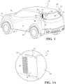
- an example vehicle 12 is shown to have a vehicle body 14 with opposite side panels 16 (sides) extending between a front end 18 (front) and rear end 20 (rear), wherein the applique assembly, referred to hereafter as assembly 10, is shown disposed, in a deployed position, on the opposite side panels 16 immediately adjacent the rear end 20, such as on a D-pillar of the vehicle.
- the assembly 10 includes a housing 22 having a sides 23, 24, 25.
- the housing also include a connecting flange 21 that is used for securing the bottom edge of the housing 22 to the vehicle 12.
- the housing 22 also has an external surface 26 and an opposite internal surface 28 with at least one through opening, and shown, by way of example and without limitation in FIGS.
- the assembly 10 further incudes a deployable panel 32 having an aerodynamic outer surface 34 (facing outwardly as a viewable surface of the vehicle) and an opposite inner surface 36.
- the inner surface 36 is configured to overlie at least a portion of the external surface 26 of the wall 24 when in a stowed position and the outer surface 34 is configured to face outwardly from a body panel of the vehicle 12 for viewing, shown as the side panels 16, by way of example and without limitation.
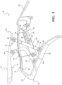
- the assembly 10 further includes at least one drive link 38 extending through at least one of the through openings 30, wherein the drive link 38 has a first end 40 pivotally coupled to a flange 41 of the inner surface 36 of the panel 32 and a second end 42 to a flange 43 on an inner surface of the wall 24.
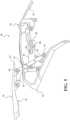
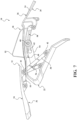
- the assembly 10 further includes an actuator 44 operably coupled with the second end 42 of the drive link 38, wherein the actuator 44 selectively drives (pivots) the drive link 38, within the through opening 30, to deploy the panel 32 from the stowed position ( FIGS. 2-2C ) to a fully deployed position ( FIGS. 7-7D ) spaced from the stowed position. It is within the scope of this invention that the actuator 44 is operable to maintain or continually move the panel 32 over an infinite number of select positions between the stowed position and the fully deployed position, depending on the conditions.
- the assembly 10 is further shown in a non-limiting embodiment as including a vortex member 46 has a body 47 with an inner face 48 and an outer face 50 with at least one protrusion, also referred to as a plurality of fins 52 that extend outwardly from the outer face 50.
- the vortex member 46 is moveable from a retracted, stowed position such that the vortex member 46 is concealed beneath the panel 32 beneath the wall of the housing 22 as shown in Figs. 2-2C .
- the plurality of fins 52 are moveable outwardly to a visibly deployed, active position, so the plurality of fins 52 pass through the respective openings 30 and extend above the external surface 26 of the wall 24 of the housing 22. When the vortex member46 are in the deployed position they act to form the desired flow of air there over to promote laminar air flow.
- Movement of the vortex member 46 occurs concurrently and conjointly with the movement of the panel from 32 from its stowed position to its deployed position, via the actuator 44 selectively pivoting the drive link 38.
- the concurrent movement results due to the incorporation of a driven link 54 that is operably coupled to the vortex member 46 and operably driven via selective movements of the drive link 38.
- the driven link 54 extends between a first end 56 and a second end 58, and is shown, in a non-limiting embodiment, as being operably coupled to one of a plurality of stabilizer links 55 for pivotal movement relative thereto at the first end 56 and is operably coupled to the vortex member 46, via a pin 60, which is shown, by way of example and without limitation, as being fixed to the vortex member 46.
- the pin 60 extends from fixed attachment to the vortex member 46 for sliding receipt within a slot 62 formed between the ends 56, 58 of the driven link 54.
- the body 47 of the vortex member is pivotally connected to a plurality of arms 67, 67', 67" that are formed as part of the housing 22, and extend from the internal surface 28.
- a pin 69, 69', 69" extends through each of the plurality of arms 67, 67', 67" and an aperture (not shown) in the body 47 to create an axis about which the body 47 of the vortex member 46 pivots.
- the fins 52 are moved upwardly into the passing air to establish the desired air flow, wherein it is to be recognized the fins 52 can be shaped as desired to establish the desired vortex air flow thereover to generate a turbulent boundary layer and to promote attachment of the airflow to the outer surface 34 downstream from fins 52.
- the fins 52 move from being concealed beneath the internal surface 28 of the wall 24 upwardly through the through openings 30, wherein each fin 52 is shown as extending through a separate through opening 30, by way of example and without limitation. Accordingly the through openings 30 can be formed to allow a close, slight clearance fit with the fins 52, thereby acting to prevent the ingress of air flow and debris therethrough.
- seal members such as annular seal lips (not shown) could be provided about the periphery of the through openings 30 to facilitate forming a barrier to the ingress of air flow and debris.
- a four-bar linkage is provided to facilitate deployment and retraction of the panel 32 and vortex member 46.
- the four-bar linkage is provided via a pair of the drive links 38, 38'.
- One of the drive link 38 is directly coupled to the actuator 44.
- Each of the drive links 38, 38' is paired with a respective one of a pair of the stabilizer links 55, 55' to form opposite side links 57, 57' of the four-bar linkage.
- the panel 32 is connected at each side link 57, 57' forming a "coupler link" of the four bar linkage.
- the wall 24, being operably coupled to an opposite respective end 65, 65', 66, 66' of each of the drive and stabilizer links 38, 38', 55, 55' forms a "frame link".
- the drive links 38, 38' are shown as being generally or substantially straight (meaning they can be truly straight or slightly less that truly straight), while the stabilizer links 55, 55' are shown as being generally or substantially L-shaped (meaning they can be truly L-shaped or slightly less that truly L-shaped), by way of example and without limitation.
- the L-shape of the stabilizer links 55 allows the through openings 30 to be reduced in length, thereby minimizing the possibility of water or debris from entering the housing 22.
- the stabilizer links 55, 55' could be straight, though it would require lengthening the corresponding through openings 30. Accordingly, it is to be recognized that the elongate shape of the respective links can be other that shown.
- the external surface 26 of the housing 22 can be formed having a recessed surface, also referred to as pocket 68, configured for receipt of the panel 32 therein.
- the shape of an outer periphery 70 and depth (D) of the pocket 68 can be formed such that when the panel 32 is retracted to its fully stowed position, a smooth, generally seamless outwardly facing surface of the vehicle body, shown as the side panels 16, is formed.
- depth (D) can vary as desired to accommodate a varying thickness of the panel 32, and the outer surface 34 of the panel 32 can be formed having any desired aesthetic appearance and contour, as desired.
- the actuator 44 can be provided as any desired actuator capable of selectively deploying and retracting the panel 32 between the stowed and deployed positions, and in accordance with one aspect, is provided as an electric motor 72 operably connected, such as via an intermediate gear train 74, to a drive member, shown as a flexible drive shaft 76.
- a drive member shown as a flexible drive shaft 76.
- any suitable coupling between the drive shaft 76 and the drive link 38 can be implemented to cause conjoint pivoting, oscillating movement of the drive link 38 depending on the direction of rotation of the drive shaft 76. Accordingly, rotation of the drive shaft 76 in one direction causes corresponding pivoting movement of the drive link 38 in the same direction, and rotation of the drive shaft 76 in an opposite direction causes corresponding pivoting movement of the drive link 38 in the same direction.
- the panel 32 and vortex member 46 are selectively deployable and retractable as needed to establish the desired laminar airflow about the rear end 20 of the vehicle 12.
- the assembly 10 can be configured in operable, electrical communication via an electrical connection 77 with an electronic control unit (ECU) 78 or body control unit (BCM), which in turn can be configured in electrical communication via an electrical connection 77 with a sensor 80, such as anemometer, to other speed sensor, such as a speedometer or connection to the ECU/BCM (having data about the vehicle speed acquired from various sensor(s)), by way of example and without limitation, wherein the assembly 10 can be further configured to deploy above or retract below a predetermined speed threshold.
- ECU electronice control unit
- BCM body control unit
- the electronic control unit 78 can be configured to receive information, such a wind speed, wind direction, type of airflow (laminar or turbulent) from the sensor 80, and in turn, can selectively actuate the electric motor 72 to drive the panel 32 between the desired stowed and deployed positions, wherein the panel 32 can be deployed to an infinite number of positions between the stowed and fully deployed positions to establish an optimal airflow about the rear end 20 of the vehicle to minimize the base drag (low pressure) behind the vehicle 12, thereby enhancing the fuel economy of the vehicle.
- information such as a wind speed, wind direction, type of airflow (laminar or turbulent) from the sensor 80
- the electric motor 72 to drive the panel 32 between the desired stowed and deployed positions
- the panel 32 can be deployed to an infinite number of positions between the stowed and fully deployed positions to establish an optimal airflow about the rear end 20 of the vehicle to minimize the base drag (low pressure) behind the vehicle 12, thereby enhancing the fuel economy of the vehicle.
- the panels 32 can remain in their stowed positions, thereby remaining flush with the side panels 16 and with the rear end 20. Accordingly, with the assembly 10 in the non-deployed state, and the panels 32 and vortex members 46 are in their stowed positions, the vehicle 12 takes on a "normal" appearance.
- the panels 32 and vortex members 46 can be conjointly deployed, as commanded by the electronic control unit 78 via signals from the sensor(s) 80, via selective actuation of the motor 72 and drive shaft 76.
- the four-bar linkage keeps the panels 32 in relatively close relation to the side panels 16, thereby minimizing a head-on drag forces from wind flowing about the panels 32.
- the driven links 54 are simultaneously moved to move the vortex members 46 to their deployed positions, with the fins 52 be driven outwardly through their respective through openings 30.
- the outer surfaces 34 and outer faces 50 thereof are brought into flush or substantially flush relation with the vehicle side panels 16, thus preventing head-on drag.
- the panels 32 are extended rearwardly of the rear end 20 to prevent or inhibit the separation of the airflow from the vehicle rear end 20.
- the panels 32 can be shaped to form a tear drop configuration rearwardly from the rear end 20, if desired, or they could be shaped otherwise, including having flat or substantially flat outer surfaces 34 oriented to extend inwardly in converging relation with one another, if desired.
- the assembly 10 can be actuated directly by the user, such as via a switch or button with a cabin of the vehicle, as desired.
- assembly including the panel 32 and vortex member 46, can be configured, shaped and contoured as desired, and that the foregoing description of the embodiments has been provided for purposes of illustration and description. It is not intended to be exhaustive or to limit the disclosure. Individual elements, assemblies/subassemblies, or features of a particular embodiment are generally not limited to that particular embodiment, but, where applicable, are interchangeable and can be used in a selected embodiment, even if not specifically shown or described. The same may also be varied in many ways. Such variations are not to be regarded as a departure from the disclosure, and all such modifications are intended to be included within the scope of the disclosure.
Landscapes
- Engineering & Computer Science (AREA)
- Chemical & Material Sciences (AREA)
- Combustion & Propulsion (AREA)
- Transportation (AREA)
- Mechanical Engineering (AREA)
- Physics & Mathematics (AREA)
- Fluid Mechanics (AREA)
- Fittings On The Vehicle Exterior For Carrying Loads, And Devices For Holding Or Mounting Articles (AREA)
- Body Structure For Vehicles (AREA)
Claims (15)
- Assemblage d'applique déployable (10) pour un véhicule à moteur (12), comprenant :un boîtier (12) ayant une paroi (24) avec une surface externe (26) et au moins une ouverture traversante (30) qui s'étend à travers la paroi (24) ;un panneau (32) configuré pour recouvrir au moins une portion de la surface externe (26) de la paroi (24) quand il est dans une position escamotée ;une liaison d'entraînement (38) qui s'étend à travers ladite au moins une ouverture traversante (30) et qui a une première extrémité (40) couplée de manière fonctionnelle à la surface intérieure (36) du panneau (32) et une seconde extrémité (42) couplée de manière pivotante à une bride (43) sur une surface intérieure de la paroi (24) ; etun actionneur (44) à l'intérieur du boîtier (22) et connecté à la seconde extrémité (42) de la liaison d'entraînement (38), l'actionneur (44) déplaçant sélectivement la liaison d'entraînement (38) à l'intérieur de l'ouverture traversante (30) pour déplacer le panneau (32) entre la position escamotée et une position déployée espacée de la position escamotée.
- Assemblage d'applique déployable (10) selon la revendication 1, comprenant en outre :le boîtier (22) qui a une surface interne opposée (28) ; etle panneau (32) qui a une surface extérieure (34) et une surface intérieure (36), la surface intérieure (36) étant configurée pour recouvrir au moins une portion de la surface externe (26) de la paroi (24) quand il est dans une position escamotée, et la surface extérieure (34) étant configurée pour être tournée vers l'extérieur par rapport à panneau de carrosserie (32) du véhicule à moteur (12) pour être vue.
- Assemblage d'applique déployable (10) selon la revendication 1 ou 2, incluant en outre un élément tourbillonnaire (46) ayant une face intérieure (48) et une face extérieure (50) avec au moins une ailette (52) s'étendant vers l'extérieur par rapport à la face extérieure (50), l'élément tourbillonnaire (46) pouvant être déplacé depuis une position escamotée rétractée en dessous du panneau (32) jusqu'à une position déployée extérieurement visible en même temps que le déplacement du panneau (32) depuis sa position escamotée jusqu'à sa position déployée via l'actionneur (44) qui pivote sélectivement la liaison d'entraînement (38).
- Assemblage d'applique déployable (10) selon la revendication 3, dans lequel l'élément tourbillonnaire (46) inclut une pluralité desdites au moins une ailette (52).
- Assemblage d'applique déployable (10) selon la revendication 4, dans lequel le boîtier (22) a une pluralité desdites au moins une ouverture traversante (30), dans lequel chacune des ailettes (52) s'étend à travers une ouverture séparée des ouvertures traversantes (30).
- Assemblage d'applique déployable (10) selon la revendication 5, dans lequel la liaison d'entraînement (38) s'étend à travers une ouverture séparée des ouvertures traversantes (30) depuis les ailettes (52).
- Assemblage d'applique déployable (10) selon la revendication 3, incluant en outre une liaison d'entraînement (54) connectée à l'élément tourbillonnaire (46), dans lequel la liaison d'entraînement (54) est entraînée par un déplacement de la liaison d'entraînement (38).
- Assemblage d'applique déployable (10) selon la revendication 7, dans lequel la liaison d'entraînement (54) a une fente allongée (62), et incluant en outre une broche (60) s'étendant en relation fixe depuis l'élément tourbillonnaire (46) jusque dans un logement coulissant à l'intérieur de la fente (62).
- Assemblage d'applique déployable (10) selon la revendication 1 ou 2, dans lequel la seconde extrémité (42) de la liaison d'entraînement (38) est couplée de manière fonctionnelle au boîtier (22), et incluant en outre une liaison de stabilisation (55) qui a une première extrémité couplée de manière fonctionnelle à la surface intérieure (36) du panneau (32) et une seconde extrémité couplée de manière fonctionnelle au boîtier (22), la liaison d'entraînement (38) et la liaison de stabilisation (55) formant une liaison à quatre barres avec le panneau (32) et le boîtier (22).
- Assemblage d'applique déployable (10) selon la revendication 9, dans lequel la liaison d'entraînement (38) est sensiblement rectiligne et la liaison de stabilisation (55) est généralement en forme de L.
- Assemblage d'applique déployable (10) selon la revendication 1 ou 2, dans lequel la surface externe (26) du boîtier (22) a une poche évidée (68) jointoyée par une périphérie extérieure (70), le panneau (32) étant configuré pour être reçu dans la poche évidée, la surface extérieure (34) du panneau (32) étant généralement en affleurement avec la périphérie extérieure (70) tandis que le panneau (32) est dans la position escamotée.
- Assemblage d'applique déployable (10) selon la revendication 1 ou 2, dans lequel l'actionneur (44) inclut un moteur électrique (72) couplé de manière fonctionnelle à la seconde extrémité (42) de la liaison d'entraînement (38) via un élément d'entraînement flexible.
- Assemblage d'applique déployable (10) selon la revendication 12 , dans lequel le moteur électrique (72) est configuré en communication fonctionnelle avec une unité de commande électronique (78), l'unité de commande électronique (78) étant configurée pour indiquer quand il faut actionner sélectivement le moteur électrique (72) pour entraîner le panneau (32) entre les positions escamotée et déployée.
- Assemblage d'applique déployable (10) selon la revendication 13, dans lequel l'unité de commande électronique (78) est en communication (fonctionnelle) avec un capteur (80), le capteur (80) étant configuré pour indiquer à l'unité de commande électronique (78) quand il faut actionner le moteur électrique (72).
- Assemblage d'applique déployable (10) selon la revendication 1 ou 2, dans lequel le panneau (32) est configuré pour être généralement en affleurement avec le panneau de carrosserie (32) du véhicule (12) et avec une surface arrière (20) du véhicule à moteur (12) quand il est dans sa position escamotée, et pour s'étendre vers l'arrière de la surface arrière (20) quand il est dans sa position déployée ;
dans lequel le panneau (32) est de préférence configuré pour être généralement en affleurement avec le panneau de carrosserie (32) du véhicule (12) quand il est dans sa position déployée.
Applications Claiming Priority (2)
| Application Number | Priority Date | Filing Date | Title |
|---|---|---|---|
| US201762610600P | 2017-12-27 | 2017-12-27 | |
| PCT/IB2018/060621 WO2019130218A1 (fr) | 2017-12-27 | 2018-12-26 | Applique à surface aérodynamique déployable |
Publications (3)
| Publication Number | Publication Date |
|---|---|
| EP3732092A1 EP3732092A1 (fr) | 2020-11-04 |
| EP3732092A4 EP3732092A4 (fr) | 2021-05-12 |
| EP3732092B1 true EP3732092B1 (fr) | 2023-09-06 |
Family
ID=67066730
Family Applications (1)
| Application Number | Title | Priority Date | Filing Date |
|---|---|---|---|
| EP18894342.7A Active EP3732092B1 (fr) | 2017-12-27 | 2018-12-26 | Applique à surface aérodynamique déployable |
Country Status (5)
| Country | Link |
|---|---|
| US (1) | US11338867B2 (fr) |
| EP (1) | EP3732092B1 (fr) |
| CN (1) | CN111511632B (fr) |
| CA (1) | CA3084033C (fr) |
| WO (1) | WO2019130218A1 (fr) |
Families Citing this family (10)
| Publication number | Priority date | Publication date | Assignee | Title |
|---|---|---|---|---|
| WO2018163528A1 (fr) * | 2017-03-06 | 2018-09-13 | 株式会社ホンダアクセス | Élément aérodynamique pour automobiles |
| US10569786B2 (en) * | 2017-04-13 | 2020-02-25 | Blackberry Limited | Parameters sets for vehicles based on sensor data |
| GB2577313B (en) * | 2018-09-21 | 2022-07-13 | Mclaren Automotive Ltd | Variable aerodynamic device |
| DE102022202731A1 (de) * | 2021-05-18 | 2022-11-24 | Magna Car Top Systems Gmbh | Strömungsleitvorrichtung für ein Kraftfahrzeug |
| DE102021117255A1 (de) * | 2021-07-05 | 2023-01-05 | Dr. Ing. H.C. F. Porsche Aktiengesellschaft | Kraftfahrzeug-Seitenspoileranordnung |
| DE102021117866A1 (de) * | 2021-07-12 | 2023-01-12 | Dr. Ing. H.C. F. Porsche Aktiengesellschaft | Luftleitvorrichtung eines Kraftfahrzeugs |
| DE102021117867B4 (de) * | 2021-07-12 | 2024-08-01 | Dr. Ing. H.C. F. Porsche Aktiengesellschaft | Kraftfahrzeug mit einer Luftleitvorrichtung |
| US11866032B2 (en) * | 2021-08-06 | 2024-01-09 | GM Global Technology Operations LLC | System and method for controlling electronic limited slip differential and active aerodynamic actuator on vehicle |
| US11891127B2 (en) | 2021-09-01 | 2024-02-06 | Honda Motor Co., Ltd. | Drag reduction spoiler |
| US11939005B2 (en) | 2021-11-23 | 2024-03-26 | Honda Motor Co., Ltd. | Deployable active D-pillar spoiler for vehicles |
Family Cites Families (19)
| Publication number | Priority date | Publication date | Assignee | Title |
|---|---|---|---|---|
| US6666498B1 (en) | 2001-10-04 | 2003-12-23 | W. David Whitten | Deployable airfoil for trucks and trailers |
| DE10309369A1 (de) | 2003-03-03 | 2004-09-23 | Wilhelm Karmann Gmbh | Kraftfahrzeug |
| FR2869584B1 (fr) | 2004-04-28 | 2006-08-25 | Peugeot Citroen Automobiles Sa | Dispositif aerodynamique pour un vehicule automobile et vehicule automobile equipe d'un tel dispositif aerodynamique |
| DE102005021832A1 (de) * | 2005-05-11 | 2006-11-23 | Webasto Ag | Luftleitvorrichtung eines Fahrzeugs |
| FR2892993B1 (fr) | 2005-11-10 | 2009-04-17 | Peugeot Citroen Automobiles Sa | Dispositif aerodynamique pour un vehicule automobile et vehicule automobile comportant au moins un tel dispositif aerodynamique. |
| FR2892994B1 (fr) | 2005-11-10 | 2008-02-15 | Peugeot Citroen Automobiles Sa | Systeme aerodynamique pour un vehicule automobile et vehicule automobile comportant au moins un tel systeme. |
| DE202009002622U1 (de) * | 2009-02-25 | 2010-07-22 | Brose Fahrzeugteile Gmbh & Co. Kommanditgesellschaft, Hallstadt | Antriebsanordnung zur Betätigung einer Klappe eines Kraftfahrzeugs |
| DE102010008332A1 (de) * | 2010-02-17 | 2011-08-18 | GM Global Technology Operations LLC, ( n. d. Ges. d. Staates Delaware ), Mich. | Fahrzeug mit zumindest einem Strömungsbeeinflussungselement mit einer Abrisskante und Verfahren zur Beeinflussung eines Luftwiderstandes eines Fahrzeugs |
| JP5303598B2 (ja) * | 2011-03-30 | 2013-10-02 | 本田技研工業株式会社 | 車体側部構造 |
| WO2013043890A1 (fr) | 2011-09-20 | 2013-03-28 | Advanced Transit Dynamics, Inc. | Structure aérodynamique rétractable à montage arrière pour corps de chargement |
| DE102012102671A1 (de) | 2012-03-28 | 2013-10-02 | Scambia Holdings Cyprus Ltd. | Windabweiser |
| KR101543123B1 (ko) * | 2013-12-20 | 2015-08-07 | 현대자동차주식회사 | 차량용 가변 리어 스포일러의 링크장치 |
| CN106536334B (zh) * | 2014-06-11 | 2019-08-16 | 麦格纳外饰公司 | 主动式前导流器 |
| GB2528929B (en) | 2014-08-05 | 2018-10-31 | Jaguar Land Rover Ltd | Vehicle aerodynamic apparatus |
| GB2546850B (en) | 2014-08-05 | 2018-06-06 | Jaguar Land Rover Ltd | Vehicle aerodynamic apparatus |
| GB2545401B (en) | 2015-12-09 | 2020-01-08 | Jaguar Land Rover Ltd | Motor vehicle active wing apparatus and method |
| DE102016105081A1 (de) * | 2016-03-18 | 2017-09-21 | Dr. Ing. H.C. F. Porsche Aktiengesellschaft | Luftleitvorrichtung und Verfahren zum Betrieb einer Luftleitvorrichtung sowie Kraftfahrzeugkarosserie |
| FR3059964B1 (fr) | 2016-12-14 | 2020-01-17 | Compagnie Plastic Omnium | Becquet pour vehicule automobile comprenant des ecopes mobiles |
| DE102017004964B4 (de) | 2017-05-24 | 2021-04-08 | Daimler Ag | Karosserieteil für ein Fahrzeug und Fahrzeug mit einem solchen Karosserieteil |
-
2018
- 2018-12-26 EP EP18894342.7A patent/EP3732092B1/fr active Active
- 2018-12-26 CN CN201880083449.5A patent/CN111511632B/zh active Active
- 2018-12-26 WO PCT/IB2018/060621 patent/WO2019130218A1/fr unknown
- 2018-12-26 US US16/766,861 patent/US11338867B2/en active Active
- 2018-12-26 CA CA3084033A patent/CA3084033C/fr active Active
Also Published As
| Publication number | Publication date |
|---|---|
| CN111511632B (zh) | 2022-11-15 |
| CN111511632A (zh) | 2020-08-07 |
| US11338867B2 (en) | 2022-05-24 |
| CA3084033A1 (fr) | 2019-07-04 |
| EP3732092A4 (fr) | 2021-05-12 |
| WO2019130218A1 (fr) | 2019-07-04 |
| EP3732092A1 (fr) | 2020-11-04 |
| CA3084033C (fr) | 2022-10-18 |
| US20200369331A1 (en) | 2020-11-26 |
Similar Documents
| Publication | Publication Date | Title |
|---|---|---|
| EP3732092B1 (fr) | Applique à surface aérodynamique déployable | |
| EP3177508B1 (fr) | Modification des performances aérodynamiques d'un véhicule | |
| EP3177513B1 (fr) | Appareil aérodynamique de véhicule | |
| US10040491B2 (en) | Vehicle airflow control apparatus | |
| US7862102B1 (en) | Apparatus for reducing drag on vehicles | |
| US11383772B2 (en) | Rear air guide device for a vehicle | |
| GB2539975A (en) | Deployable pedestrian safety device for vehicles | |
| US20170240225A1 (en) | Modifying aerodynamic performance of a vehicle | |
| EP2456655B1 (fr) | Structure de régulation d'écoulement d'air de couche limite de véhicule | |
| CN111086466A (zh) | 车辆车窗装饰板总成以及车辆后视镜总成 | |
| EP2456656B1 (fr) | Structure de régulation d écoulement d'air de couche limite de véhicule | |
| US20230057190A1 (en) | Air guide device for a motor vehicle | |
| US11858563B2 (en) | Aerodynamic rear fences for vehicles | |
| US20230159114A1 (en) | Deployable Active D-Pillar Spoiler for Vehicles | |
| EP2607172B1 (fr) | Ensemble rétroviseur latéral de vue arrière | |
| CA2245308C (fr) | Retroviseur a profil aerodynamique | |
| CN114056443A (zh) | 机动车辆的后扰流件 | |
| CN112706844A (zh) | 可收起到可动扰流件中的倒车摄像头 | |
| WO2015191484A1 (fr) | Extensions de déflecteur d'air de toit ouvrant de véhicule | |
| JP2827519B2 (ja) | エアスポイラ装置 | |
| Sinha et al. | A high performance airfoil-profile deflector for open sunroof wind noise | |
| US11891126B2 (en) | Active rear diffuser for vehicle | |
| MXPA98006802A (en) | Outer mirror helmet aerodinam |
Legal Events
| Date | Code | Title | Description |
|---|---|---|---|
| STAA | Information on the status of an ep patent application or granted ep patent |
Free format text: STATUS: THE INTERNATIONAL PUBLICATION HAS BEEN MADE |
|
| PUAI | Public reference made under article 153(3) epc to a published international application that has entered the european phase |
Free format text: ORIGINAL CODE: 0009012 |
|
| STAA | Information on the status of an ep patent application or granted ep patent |
Free format text: STATUS: REQUEST FOR EXAMINATION WAS MADE |
|
| 17P | Request for examination filed |
Effective date: 20200723 |
|
| AK | Designated contracting states |
Kind code of ref document: A1 Designated state(s): AL AT BE BG CH CY CZ DE DK EE ES FI FR GB GR HR HU IE IS IT LI LT LU LV MC MK MT NL NO PL PT RO RS SE SI SK SM TR |
|
| AX | Request for extension of the european patent |
Extension state: BA ME |
|
| DAV | Request for validation of the european patent (deleted) | ||
| DAX | Request for extension of the european patent (deleted) | ||
| A4 | Supplementary search report drawn up and despatched |
Effective date: 20210413 |
|
| RIC1 | Information provided on ipc code assigned before grant |
Ipc: B62D 35/00 20060101AFI20210407BHEP Ipc: F15D 1/12 20060101ALI20210407BHEP Ipc: B62D 37/02 20060101ALI20210407BHEP |
|
| GRAP | Despatch of communication of intention to grant a patent |
Free format text: ORIGINAL CODE: EPIDOSNIGR1 |
|
| STAA | Information on the status of an ep patent application or granted ep patent |
Free format text: STATUS: GRANT OF PATENT IS INTENDED |
|
| INTG | Intention to grant announced |
Effective date: 20230404 |
|
| P01 | Opt-out of the competence of the unified patent court (upc) registered |
Effective date: 20230517 |
|
| GRAS | Grant fee paid |
Free format text: ORIGINAL CODE: EPIDOSNIGR3 |
|
| GRAA | (expected) grant |
Free format text: ORIGINAL CODE: 0009210 |
|
| STAA | Information on the status of an ep patent application or granted ep patent |
Free format text: STATUS: THE PATENT HAS BEEN GRANTED |
|
| AK | Designated contracting states |
Kind code of ref document: B1 Designated state(s): AL AT BE BG CH CY CZ DE DK EE ES FI FR GB GR HR HU IE IS IT LI LT LU LV MC MK MT NL NO PL PT RO RS SE SI SK SM TR |
|
| REG | Reference to a national code |
Ref country code: GB Ref legal event code: FG4D |
|
| REG | Reference to a national code |
Ref country code: CH Ref legal event code: EP |
|
| REG | Reference to a national code |
Ref country code: IE Ref legal event code: FG4D |
|
| REG | Reference to a national code |
Ref country code: DE Ref legal event code: R096 Ref document number: 602018057265 Country of ref document: DE |
|
| REG | Reference to a national code |
Ref country code: LT Ref legal event code: MG9D |
|
| REG | Reference to a national code |
Ref country code: NL Ref legal event code: MP Effective date: 20230906 |
|
| PG25 | Lapsed in a contracting state [announced via postgrant information from national office to epo] |
Ref country code: GR Free format text: LAPSE BECAUSE OF FAILURE TO SUBMIT A TRANSLATION OF THE DESCRIPTION OR TO PAY THE FEE WITHIN THE PRESCRIBED TIME-LIMIT Effective date: 20231207 |
|
| PGFP | Annual fee paid to national office [announced via postgrant information from national office to epo] |
Ref country code: GB Payment date: 20231102 Year of fee payment: 6 |
|
| PG25 | Lapsed in a contracting state [announced via postgrant information from national office to epo] |
Ref country code: SE Free format text: LAPSE BECAUSE OF FAILURE TO SUBMIT A TRANSLATION OF THE DESCRIPTION OR TO PAY THE FEE WITHIN THE PRESCRIBED TIME-LIMIT Effective date: 20230906 Ref country code: RS Free format text: LAPSE BECAUSE OF FAILURE TO SUBMIT A TRANSLATION OF THE DESCRIPTION OR TO PAY THE FEE WITHIN THE PRESCRIBED TIME-LIMIT Effective date: 20230906 Ref country code: NO Free format text: LAPSE BECAUSE OF FAILURE TO SUBMIT A TRANSLATION OF THE DESCRIPTION OR TO PAY THE FEE WITHIN THE PRESCRIBED TIME-LIMIT Effective date: 20231206 Ref country code: LV Free format text: LAPSE BECAUSE OF FAILURE TO SUBMIT A TRANSLATION OF THE DESCRIPTION OR TO PAY THE FEE WITHIN THE PRESCRIBED TIME-LIMIT Effective date: 20230906 Ref country code: LT Free format text: LAPSE BECAUSE OF FAILURE TO SUBMIT A TRANSLATION OF THE DESCRIPTION OR TO PAY THE FEE WITHIN THE PRESCRIBED TIME-LIMIT Effective date: 20230906 Ref country code: HR Free format text: LAPSE BECAUSE OF FAILURE TO SUBMIT A TRANSLATION OF THE DESCRIPTION OR TO PAY THE FEE WITHIN THE PRESCRIBED TIME-LIMIT Effective date: 20230906 Ref country code: GR Free format text: LAPSE BECAUSE OF FAILURE TO SUBMIT A TRANSLATION OF THE DESCRIPTION OR TO PAY THE FEE WITHIN THE PRESCRIBED TIME-LIMIT Effective date: 20231207 Ref country code: FI Free format text: LAPSE BECAUSE OF FAILURE TO SUBMIT A TRANSLATION OF THE DESCRIPTION OR TO PAY THE FEE WITHIN THE PRESCRIBED TIME-LIMIT Effective date: 20230906 |
|
| PGFP | Annual fee paid to national office [announced via postgrant information from national office to epo] |
Ref country code: FR Payment date: 20231108 Year of fee payment: 6 Ref country code: DE Payment date: 20231031 Year of fee payment: 6 |
|
| REG | Reference to a national code |
Ref country code: AT Ref legal event code: MK05 Ref document number: 1608200 Country of ref document: AT Kind code of ref document: T Effective date: 20230906 |
|
| PG25 | Lapsed in a contracting state [announced via postgrant information from national office to epo] |
Ref country code: NL Free format text: LAPSE BECAUSE OF FAILURE TO SUBMIT A TRANSLATION OF THE DESCRIPTION OR TO PAY THE FEE WITHIN THE PRESCRIBED TIME-LIMIT Effective date: 20230906 |
|
| PG25 | Lapsed in a contracting state [announced via postgrant information from national office to epo] |
Ref country code: IS Free format text: LAPSE BECAUSE OF FAILURE TO SUBMIT A TRANSLATION OF THE DESCRIPTION OR TO PAY THE FEE WITHIN THE PRESCRIBED TIME-LIMIT Effective date: 20240106 |
|
| PG25 | Lapsed in a contracting state [announced via postgrant information from national office to epo] |
Ref country code: AT Free format text: LAPSE BECAUSE OF FAILURE TO SUBMIT A TRANSLATION OF THE DESCRIPTION OR TO PAY THE FEE WITHIN THE PRESCRIBED TIME-LIMIT Effective date: 20230906 |
|
| PG25 | Lapsed in a contracting state [announced via postgrant information from national office to epo] |
Ref country code: ES Free format text: LAPSE BECAUSE OF FAILURE TO SUBMIT A TRANSLATION OF THE DESCRIPTION OR TO PAY THE FEE WITHIN THE PRESCRIBED TIME-LIMIT Effective date: 20230906 |
|
| PG25 | Lapsed in a contracting state [announced via postgrant information from national office to epo] |
Ref country code: SM Free format text: LAPSE BECAUSE OF FAILURE TO SUBMIT A TRANSLATION OF THE DESCRIPTION OR TO PAY THE FEE WITHIN THE PRESCRIBED TIME-LIMIT Effective date: 20230906 Ref country code: RO Free format text: LAPSE BECAUSE OF FAILURE TO SUBMIT A TRANSLATION OF THE DESCRIPTION OR TO PAY THE FEE WITHIN THE PRESCRIBED TIME-LIMIT Effective date: 20230906 Ref country code: IS Free format text: LAPSE BECAUSE OF FAILURE TO SUBMIT A TRANSLATION OF THE DESCRIPTION OR TO PAY THE FEE WITHIN THE PRESCRIBED TIME-LIMIT Effective date: 20240106 Ref country code: ES Free format text: LAPSE BECAUSE OF FAILURE TO SUBMIT A TRANSLATION OF THE DESCRIPTION OR TO PAY THE FEE WITHIN THE PRESCRIBED TIME-LIMIT Effective date: 20230906 Ref country code: EE Free format text: LAPSE BECAUSE OF FAILURE TO SUBMIT A TRANSLATION OF THE DESCRIPTION OR TO PAY THE FEE WITHIN THE PRESCRIBED TIME-LIMIT Effective date: 20230906 Ref country code: CZ Free format text: LAPSE BECAUSE OF FAILURE TO SUBMIT A TRANSLATION OF THE DESCRIPTION OR TO PAY THE FEE WITHIN THE PRESCRIBED TIME-LIMIT Effective date: 20230906 Ref country code: AT Free format text: LAPSE BECAUSE OF FAILURE TO SUBMIT A TRANSLATION OF THE DESCRIPTION OR TO PAY THE FEE WITHIN THE PRESCRIBED TIME-LIMIT Effective date: 20230906 Ref country code: PT Free format text: LAPSE BECAUSE OF FAILURE TO SUBMIT A TRANSLATION OF THE DESCRIPTION OR TO PAY THE FEE WITHIN THE PRESCRIBED TIME-LIMIT Effective date: 20240108 Ref country code: SK Free format text: LAPSE BECAUSE OF FAILURE TO SUBMIT A TRANSLATION OF THE DESCRIPTION OR TO PAY THE FEE WITHIN THE PRESCRIBED TIME-LIMIT Effective date: 20230906 |
|
| PG25 | Lapsed in a contracting state [announced via postgrant information from national office to epo] |
Ref country code: PL Free format text: LAPSE BECAUSE OF FAILURE TO SUBMIT A TRANSLATION OF THE DESCRIPTION OR TO PAY THE FEE WITHIN THE PRESCRIBED TIME-LIMIT Effective date: 20230906 Ref country code: IT Free format text: LAPSE BECAUSE OF FAILURE TO SUBMIT A TRANSLATION OF THE DESCRIPTION OR TO PAY THE FEE WITHIN THE PRESCRIBED TIME-LIMIT Effective date: 20230906 |
|
| REG | Reference to a national code |
Ref country code: DE Ref legal event code: R097 Ref document number: 602018057265 Country of ref document: DE |
|
| PG25 | Lapsed in a contracting state [announced via postgrant information from national office to epo] |
Ref country code: DK Free format text: LAPSE BECAUSE OF FAILURE TO SUBMIT A TRANSLATION OF THE DESCRIPTION OR TO PAY THE FEE WITHIN THE PRESCRIBED TIME-LIMIT Effective date: 20230906 |
|
| PLBE | No opposition filed within time limit |
Free format text: ORIGINAL CODE: 0009261 |
|
| STAA | Information on the status of an ep patent application or granted ep patent |
Free format text: STATUS: NO OPPOSITION FILED WITHIN TIME LIMIT |
|
| PG25 | Lapsed in a contracting state [announced via postgrant information from national office to epo] |
Ref country code: DK Free format text: LAPSE BECAUSE OF FAILURE TO SUBMIT A TRANSLATION OF THE DESCRIPTION OR TO PAY THE FEE WITHIN THE PRESCRIBED TIME-LIMIT Effective date: 20230906 Ref country code: SI Free format text: LAPSE BECAUSE OF FAILURE TO SUBMIT A TRANSLATION OF THE DESCRIPTION OR TO PAY THE FEE WITHIN THE PRESCRIBED TIME-LIMIT Effective date: 20230906 |
|
| REG | Reference to a national code |
Ref country code: CH Ref legal event code: PL |
|
| 26N | No opposition filed |
Effective date: 20240607 |
|
| PG25 | Lapsed in a contracting state [announced via postgrant information from national office to epo] |
Ref country code: LU Free format text: LAPSE BECAUSE OF NON-PAYMENT OF DUE FEES Effective date: 20231226 |
|
| PG25 | Lapsed in a contracting state [announced via postgrant information from national office to epo] |
Ref country code: MC Free format text: LAPSE BECAUSE OF FAILURE TO SUBMIT A TRANSLATION OF THE DESCRIPTION OR TO PAY THE FEE WITHIN THE PRESCRIBED TIME-LIMIT Effective date: 20230906 |
|
| REG | Reference to a national code |
Ref country code: BE Ref legal event code: MM Effective date: 20231231 |
|
| PG25 | Lapsed in a contracting state [announced via postgrant information from national office to epo] |
Ref country code: MC Free format text: LAPSE BECAUSE OF FAILURE TO SUBMIT A TRANSLATION OF THE DESCRIPTION OR TO PAY THE FEE WITHIN THE PRESCRIBED TIME-LIMIT Effective date: 20230906 Ref country code: LU Free format text: LAPSE BECAUSE OF NON-PAYMENT OF DUE FEES Effective date: 20231226 |