EP3730016A2 - Profilsystem - Google Patents
Profilsystem Download PDFInfo
- Publication number
- EP3730016A2 EP3730016A2 EP20171017.5A EP20171017A EP3730016A2 EP 3730016 A2 EP3730016 A2 EP 3730016A2 EP 20171017 A EP20171017 A EP 20171017A EP 3730016 A2 EP3730016 A2 EP 3730016A2
- Authority
- EP
- European Patent Office
- Prior art keywords
- section
- profile
- profile system
- plug
- longitudinal direction
- Prior art date
- Legal status (The legal status is an assumption and is not a legal conclusion. Google has not performed a legal analysis and makes no representation as to the accuracy of the status listed.)
- Granted
Links
Images







Classifications
-
- A—HUMAN NECESSITIES
- A47—FURNITURE; DOMESTIC ARTICLES OR APPLIANCES; COFFEE MILLS; SPICE MILLS; SUCTION CLEANERS IN GENERAL
- A47K—SANITARY EQUIPMENT; ACCESSORIES THEREFOR, e.g. TOILET ACCESSORIES
- A47K17/00—Other sanitary equipment not covered by the other groups of this subclass ; Holders for toilet brushes
- A47K17/02—Body supports, other than seats, for closets, e.g. handles, back-rests, foot-rests; Accessories for closets, e.g. reading tables
- A47K17/022—Wall mounted grab bars or handles, with or without support on the floor
-
- E—FIXED CONSTRUCTIONS
- E04—BUILDING
- E04B—GENERAL BUILDING CONSTRUCTIONS; WALLS, e.g. PARTITIONS; ROOFS; FLOORS; CEILINGS; INSULATION OR OTHER PROTECTION OF BUILDINGS
- E04B1/00—Constructions in general; Structures which are not restricted either to walls, e.g. partitions, or floors or ceilings or roofs
- E04B1/38—Connections for building structures in general
- E04B1/58—Connections for building structures in general of bar-shaped building elements
-
- A—HUMAN NECESSITIES
- A47—FURNITURE; DOMESTIC ARTICLES OR APPLIANCES; COFFEE MILLS; SPICE MILLS; SUCTION CLEANERS IN GENERAL
- A47K—SANITARY EQUIPMENT; ACCESSORIES THEREFOR, e.g. TOILET ACCESSORIES
- A47K10/00—Body-drying implements; Toilet paper; Holders therefor
- A47K10/04—Towel racks; Towel rails; Towel rods; Towel rolls, e.g. rotatable
- A47K10/10—Towel racks; Towel rails; Towel rods; Towel rolls, e.g. rotatable characterised by being mounted on cabinets, walls, doors, or the like
-
- A—HUMAN NECESSITIES
- A47—FURNITURE; DOMESTIC ARTICLES OR APPLIANCES; COFFEE MILLS; SPICE MILLS; SUCTION CLEANERS IN GENERAL
- A47K—SANITARY EQUIPMENT; ACCESSORIES THEREFOR, e.g. TOILET ACCESSORIES
- A47K3/00—Baths; Showers; Appurtenances therefor
- A47K3/28—Showers or bathing douches
- A47K3/281—Accessories for showers or bathing douches, e.g. cleaning devices for walls or floors of showers
-
- A—HUMAN NECESSITIES
- A47—FURNITURE; DOMESTIC ARTICLES OR APPLIANCES; COFFEE MILLS; SPICE MILLS; SUCTION CLEANERS IN GENERAL
- A47K—SANITARY EQUIPMENT; ACCESSORIES THEREFOR, e.g. TOILET ACCESSORIES
- A47K3/00—Baths; Showers; Appurtenances therefor
- A47K3/28—Showers or bathing douches
- A47K3/281—Accessories for showers or bathing douches, e.g. cleaning devices for walls or floors of showers
- A47K3/282—Seats specially adapted for showers
-
- E—FIXED CONSTRUCTIONS
- E04—BUILDING
- E04F—FINISHING WORK ON BUILDINGS, e.g. STAIRS, FLOORS
- E04F19/00—Other details of constructional parts for finishing work on buildings
- E04F19/02—Borders; Finishing strips, e.g. beadings; Light coves
- E04F19/06—Borders; Finishing strips, e.g. beadings; Light coves specially designed for securing panels or masking the edges of wall- or floor-covering elements
- E04F19/062—Borders; Finishing strips, e.g. beadings; Light coves specially designed for securing panels or masking the edges of wall- or floor-covering elements used between similar elements
-
- A—HUMAN NECESSITIES
- A47—FURNITURE; DOMESTIC ARTICLES OR APPLIANCES; COFFEE MILLS; SPICE MILLS; SUCTION CLEANERS IN GENERAL
- A47K—SANITARY EQUIPMENT; ACCESSORIES THEREFOR, e.g. TOILET ACCESSORIES
- A47K2201/00—Details of connections of bathroom accessories, e.g. fixing soap or towel holder to a wall
- A47K2201/02—Connections to a wall mounted support
-
- E—FIXED CONSTRUCTIONS
- E04—BUILDING
- E04B—GENERAL BUILDING CONSTRUCTIONS; WALLS, e.g. PARTITIONS; ROOFS; FLOORS; CEILINGS; INSULATION OR OTHER PROTECTION OF BUILDINGS
- E04B1/00—Constructions in general; Structures which are not restricted either to walls, e.g. partitions, or floors or ceilings or roofs
- E04B1/38—Connections for building structures in general
- E04B1/58—Connections for building structures in general of bar-shaped building elements
- E04B2001/5881—Connections for building structures in general of bar-shaped building elements using an undercut groove, e.g. dovetail groove
-
- E—FIXED CONSTRUCTIONS
- E04—BUILDING
- E04F—FINISHING WORK ON BUILDINGS, e.g. STAIRS, FLOORS
- E04F13/00—Coverings or linings, e.g. for walls or ceilings
- E04F13/07—Coverings or linings, e.g. for walls or ceilings composed of covering or lining elements; Sub-structures therefor; Fastening means therefor
- E04F13/08—Coverings or linings, e.g. for walls or ceilings composed of covering or lining elements; Sub-structures therefor; Fastening means therefor composed of a plurality of similar covering or lining elements
- E04F13/0801—Separate fastening elements
- E04F13/0803—Separate fastening elements with load-supporting elongated furring elements between wall and covering elements
- E04F13/081—Separate fastening elements with load-supporting elongated furring elements between wall and covering elements with additional fastening elements between furring elements and covering elements
- E04F13/083—Hooking means on the back side of the covering elements
-
- E—FIXED CONSTRUCTIONS
- E04—BUILDING
- E04F—FINISHING WORK ON BUILDINGS, e.g. STAIRS, FLOORS
- E04F19/00—Other details of constructional parts for finishing work on buildings
- E04F19/02—Borders; Finishing strips, e.g. beadings; Light coves
- E04F19/06—Borders; Finishing strips, e.g. beadings; Light coves specially designed for securing panels or masking the edges of wall- or floor-covering elements
- E04F19/065—Finishing profiles with a T-shaped cross-section or the like
-
- F—MECHANICAL ENGINEERING; LIGHTING; HEATING; WEAPONS; BLASTING
- F16—ENGINEERING ELEMENTS AND UNITS; GENERAL MEASURES FOR PRODUCING AND MAINTAINING EFFECTIVE FUNCTIONING OF MACHINES OR INSTALLATIONS; THERMAL INSULATION IN GENERAL
- F16B—DEVICES FOR FASTENING OR SECURING CONSTRUCTIONAL ELEMENTS OR MACHINE PARTS TOGETHER, e.g. NAILS, BOLTS, CIRCLIPS, CLAMPS, CLIPS OR WEDGES; JOINTS OR JOINTING
- F16B7/00—Connections of rods or tubes, e.g. of non-circular section, mutually, including resilient connections
- F16B7/04—Clamping or clipping connections
- F16B7/044—Clamping or clipping connections for rods or tubes being in angled relationship
- F16B7/0446—Clamping or clipping connections for rods or tubes being in angled relationship for tubes using the innerside thereof
- F16B7/0453—Clamping or clipping connections for rods or tubes being in angled relationship for tubes using the innerside thereof the tubes being drawn towards each other
- F16B7/0466—Clamping or clipping connections for rods or tubes being in angled relationship for tubes using the innerside thereof the tubes being drawn towards each other by a screw-threaded stud with a conical tip acting on an inclined surface
Definitions
- the present invention relates to a profile system for fastening objects to a room wall provided with panel cladding, comprising at least one elongated rail profile that extends in a longitudinal direction, has a constant cross section and at least one plug-in element that is designed to be directly and detachably attached to the rail profile to be fixed positively.
- Profile systems of the type mentioned are known in the prior art in a wide variety of configurations.
- the rail profile is mounted on a wall, whereupon the at least one plug-in element can be releasably attached to the rail profile with the creation of a form fit.
- a wide variety of objects can be mounted or attached to the plug-in element or elements, such as shelves, tool holders or the like, to name just a few examples.
- a problem with known profile systems is often that the rail profile has to be fastened to the wall by means of screws, which requires holes to be drilled. This is particularly undesirable if the wall is provided with panel cladding, for example in the form of tiles, since the holes can only be filled with difficulty in such a way that they are no longer visible in the event of dismantling.
- the wall is a tiled shower wall, in which a surface seal is arranged between the wall and the tiles, the installation of the rail profile without damaging the surface seal is not possible.
- Another disadvantage is that in many profile systems the plug-in elements in the assembled state, apart from the form-fitting engagement, are usually only supported punctually or linearly on the rail profile or on the wall. Accordingly, forces acting on these are only very local in the Wall initiated. This means that the load that can be absorbed by the profile system is comparatively low. Accordingly, such profile systems can only be used to a limited extent.
- the present invention creates a profile system of the type mentioned at the outset, in which the rail profile, viewed in cross section, has a substantially rectangular base section, the depth of which is adapted to the thickness of the panel cladding and which has a longitudinally extending receiving groove on its front side an externally accessible groove opening is provided, and has at least one first fastening leg, which is essentially flush with the back of the base section and protrudes outward from the base section, the plug element has a particularly plate-shaped holding section and an elongated and attached to it having connecting section extending in the longitudinal direction, the connecting section comprising at least one web extending outwardly from the holding section and a head section which is arranged at the free end of the web and which is designed in this way forms is that it can be inserted in a first pivot position of the plug-in element with respect to a pivot axis extending in the longitudinal direction through the groove opening into the receiving groove of the rail profile and can be locked in a second pivot position within the receiving groove by pivoting the
- the formation of the rail profile is advantageous in that it can be integrated into the tile covering when tiling a wall by embedding the at least one fastening leg in the tile adhesive or thin-bed mortar used to lay the tile cladding. Accordingly, no screws are required to fasten the rail profile, which is why its installation does not impair an existing surface seal.
- the upper side of the at least one fastening leg is covered by tile adhesive and the surface covering, as a result of which a very stable arrangement is realized. In addition, a very neat appearance is achieved.
- a load-bearing element that can be pushed or slipped onto the holding section of the plug-in element is advantageous in that the plug-in element is fixed in its second position by the load-bearing element held on it, so that it cannot be accidentally released.
- the load is transferred very well into the wall via the load-bearing element lying flat against the wall. Accordingly, very high loads can be absorbed by the profile system according to the invention.
- the receiving groove When viewed in cross section, the receiving groove preferably describes an arc of circle with a first radius R1 extending over at least 200 °, the groove opening having a predetermined groove width, and the head section having a substantially cylindrical lateral surface which, viewed in cross section, is an arc of circle with the radius R2 describes, which is equal to the radius R1 or slightly smaller than this, the maximum distance between one of the circular arc delimiting the lateral surface Chord and the lateral surface is slightly smaller than the groove width (B). Thanks to such a configuration, the plug-in element can be easily inserted into the receiving groove of the rail profile and fastened to it in a form-fitting manner as part of a pivoting movement.
- Undercut recesses are advantageously provided on the rear side and / or on the upper side and / or on the underside of the base section of the rail profile.
- An adhesive or mortar with which the rail profile is attached to a wall can claw into such recesses.
- a recess is provided in the corner area between the bottom and the front of the base section and / or in the corner area between the front and the top of the base section and / or in the corner area between the top and the back of the base section, which a grout chamber defined for the absorption of grout.
- the recess is advantageously provided with an undercut, which is positioned and designed in such a way that a joint mortar introduced into the recess can dig into it.
- the fastening leg can be provided with a multiplicity of through openings which are preferably evenly spaced from one another in the longitudinal direction.
- An adhesive or mortar, with which the rail profile is fastened to a wall, can pass through such through openings, thereby ensuring a secure hold.
- the rail profile and the at least one plug-in element are preferably made of metal, in particular of aluminum or stainless steel, as a result of which very good strength and corrosion resistance are achieved.
- the holding section of the plug element is advantageously designed in the form of a plate. Many different objects can be attached to such a plate-shaped holding section, so that the plug-in element can be used flexibly.
- the web of the connecting section preferably projects at an angle in the range between 100 ° and 110 °, in particular upwards from the holding section. Such an inclined connecting section facilitates the insertion of the head section into the receiving groove.
- the head section is provided with a receiving recess which extends in the longitudinal direction and in which a rubber lip serving to compensate for tolerances is inserted.
- a rubber lip can compensate for deviations between the radii R1 and R2 in order to ensure a good fit of the head section in the receiving groove.
- the at least one load-bearing element is preferably made of metal or plastic.
- the bathroom utensil can be highly stressed utensils, such as, for example, a holding rod as it is arranged as a person support in the area of showers, bathtubs and toilets, or a shower seat. It can of course also be a matter of less stressed utensils, such as a shower shelf, a towel holder or the like.
- the Figures 1 to 16 show a profile system 1 according to a first embodiment of the present invention, which has as main components a rail profile 2, a plug-in element 3, a load-bearing element 4 and a bathroom utensil 5 in the form of a holding rod.
- the rail profile 2 is an elongated rail profile that extends in a longitudinal direction L and has a constant cross section, which in the present case is made of stainless steel. Alternatively, the rail profile 2 can also consist of aluminum or another material, such as plastic.
- the length of the rail profile 2 is normally 1000 to 3000 mm in the delivery condition and can then be shortened to any length before assembly.
- the rail profile 2, viewed in cross section, comprises an essentially rectangular base section 6 which is provided on its front side with a receiving groove 7 extending in the longitudinal direction L.
- the receiving groove 7 describes a circular arc 8 extending over an angle of at least 200 °, in the present case approximately 270 °, with a first radius R1, and is accessible via a groove opening 9 with a predetermined groove width B.
- Undercut recesses 10, 11 are provided on the back, top and bottom of the base section 6.
- the two recesses 10 provided on the rear side have the shape of a partial circle when viewed in cross section.
- the recesses 11 on the upper side and on the lower side of the base section 6 have a dovetail shape.
- recesses 12, which are provided with an undercut are also provided, which define a grout chamber.
- the rail profile 2 further comprises two fastening legs 13, which are essentially flush with the rear side of the base section 6 and protrude in opposite directions outward from the base section 6 upwards and downwards.
- Each of the fastening legs 13 is provided with a multiplicity of through openings 14, which are spaced apart from one another essentially equally in the longitudinal direction L, the uniform spacing not being mandatory.
- Figure 3 shows the rail profile 2 in the state mounted on a wall 15.
- the rail profile 2 is installed during the laying of tiles 16 on a wall 15 in a horizontal joint between two rows of tiles arranged one above the other in such a way that the fastening legs 13 are embedded in the tile adhesive 17 and the base section 6 is positioned in the joint in such a way that that the side edges of the tiles 16 rest against the bottom and the top of the base section 6.
- the tile adhesive 17 penetrates the through openings 14 of the upper fastening leg 13 and is anchored in the recesses 10 and 11, whereby a good fastening of the rail profile 2 on the wall 15 is achieved.
- joint mortar 18 is applied and clamped in the recesses 12 of the base section 6 of the rail profile 2.
- the plug element 3 which is in the Figures 4 and 5 is shown in more detail, is presently also made of stainless steel. As with the rail profile 2, other materials can also be used.
- the plug element 3 comprises a plate-shaped holding section 19 in the present case and an elongated connecting section 20 which is fastened to it and which extends in the longitudinal direction L.
- the connecting section 20 has a web 21 extending outwards from the holding section 19 and a web 21 arranged at the free end of the web 21 , cylinder-like head portion 22, the lateral surface of which, viewed in cross section, describes an arc of a circle with the radius R2, which is equal to the radius R1 or slightly or a few tenths of a millimeter smaller than this.
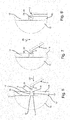
- a max between a chord 23 delimiting the circular arc which is based on Figure 4 In the present case, it extends at an angle ⁇ to the holding section 19, which is preferably in the range from 35 ° to 60 °, and the outer surface is slightly smaller than the groove width B, so that the head section 22, as shown in FIG Figure 6 is shown in a certain pivot position of the holding element 3 with respect to a pivot axis 24 extending in the longitudinal direction L through the groove opening 9 into the receiving groove 7 of the rail profile 2 in the direction of the arrow 25 and within the framework of a pivoting movement about the pivot axis 24 in the direction of the arrow 26 within the receiving groove 7 can be locked, see the Figures 7 and 8 .
- the web 21 of the connecting section 20 protrudes from the holding section 19 at an angle ⁇ of 100 ° to 110 °.
- the head section 22 is provided in the region of the circular chord 23 with a receiving recess 27 which extends in the longitudinal direction L and into which an elongated rubber lip 28 is inserted. This rubber lip 28 prevents the head section 22 from moving too easily within the receiving groove 7.
- Figure 9 shows the plug element 3 in the state in which it is attached to the rail profile 2 of FIG Figure 3 shown arrangement is attached.
- the Figures 10 and 11 show the load-bearing element 4.
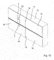
- it is plate-like and is provided on its essentially flat rear side 29 with a groove 31 which is open at the bottom and closed at the top and has undercuts 30 at the side, the dimensions of which are adapted to the holding section 19 of the plug element 3, that the load bearing element 4 starting from the in Figure 12
- the state shown can be pushed from above in the direction of arrow 32 in a form-fitting manner onto the locked holding section 19, as shown in FIG Figures 13 and 14 is shown, and in this pushed-on state lies flat against the tiles 16.
- FIGS. 15 and 16 show an arrangement in which a bathroom utensil 5 in the form of a holding rod using two plug-in elements and two load-bearing elements 4 are attached to a wall 15, the bathroom utensil 5 being firmly connected to the two load-bearing elements 4.
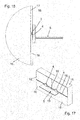
- the Figures 17 and 18 show a variant in which the bathroom utensil 5 is formed by a shower shelf.
- the variant shown is the bathroom utensil 5 is a shower seat.
- the shower seat comprises a seat part 33 which is attached to a load-bearing element 4 so as to be pivotable about a pivot axis 34, so that the seat part 34 from the in the Figures 19 and 20 horizontal position shown in Figure 21
- the vertical position shown can be swiveled when not in use.
- the load-bearing element 4 has two grooves 31, even if this is not shown here, and is pushed from above onto the holding sections 19 of two plug-in elements 3 fastened to the rail profile 2.
Landscapes
- Public Health (AREA)
- Health & Medical Sciences (AREA)
- Architecture (AREA)
- Engineering & Computer Science (AREA)
- General Health & Medical Sciences (AREA)
- Epidemiology (AREA)
- Civil Engineering (AREA)
- Structural Engineering (AREA)
- Physics & Mathematics (AREA)
- Electromagnetism (AREA)
- Finishing Walls (AREA)
- Residential Or Office Buildings (AREA)
- Joining Of Building Structures In Genera (AREA)
Abstract
Description
- Die vorliegende Erfindung betrifft ein Profilsystem zum Befestigen von Gegenständen an einer mit einer Plattenbekleidung versehenen Raumwand, umfassend zumindest ein längliches, sich in einer Längsrichtung erstreckendes, einen konstanten Querschnitt aufweisendes Schienenprofil und zumindest ein Stecktelement, das dazu ausgelegt ist, unmittelbar und lösbar an dem Schienenprofil formschlüssig befestigt zu werden.
- Profilsysteme der eingangs genannten Art sind im Stand der Technik in unterschiedlichsten Ausgestaltungen bekannt. Das Schienenprofil wird an einer Wand montiert, woraufhin das zumindest eine Steckelement lösbar an dem Schienenprofil unter Erzeugung eines Formschlusses befestigt werden kann. An dem oder den Steckelementen können unterschiedlichste Gegenstände montiert sein oder befestigt werden, wie Regalböden, Werkzeughalter oder dergleichen, um nur einige Beispiele zu nennen. Ein Problem bei bekannten Profilsystemen besteht häufig darin, dass das Schienenprofil mittels Schrauben an der Wand zu befestigen ist, was das Bohren von Löchern voraussetzt. Dies ist insbesondere dann nicht wünschenswert, wenn die Wand mit einer Plattenbekleidung versehen ist, beispielsweise in Form von Fliesen, da die Löcher im Falle einer Demontage nur schwer so verfüllt werden können, dass diese nicht mehr sichtbar sind. Handelt es sich bei der Wand um eine geflieste Duschwand, bei der zwischen Wand und Fliesen eine Flächenabdichtung angeordnet ist, so ist die Montage des Schienenprofils ohne Beschädigung der Flächenabdichtung gar nicht möglich. Ein weiterer Nachteil besteht darin, dass sich bei vielen Profilsystemen die Steckelemente im montierten Zustand abgesehen vom formschlüssigen Eingriff selbst meist nur punktuell oder linienförmig an dem Schienenprofil oder an der Wand abstützen. Entsprechend werden auf diese einwirkende Kräfte nur sehr lokal in die Wand eingeleitet. Dies führt dazu, dass die Traglast, die von dem Profilsystem aufgenommen werden kann, vergleichsweise gering ist. Entsprechend sind solche Profilsysteme nur beschränkt einsetzbar.
- Ausgehend von diesem Stand der Technik ist es eine Aufgabe der vorliegenden Erfindung, ein Profilsystem der eingangs genannten Art mit verbessertem Aufbau zu schaffen.
- Zur Lösung dieser Aufgabe schafft die vorliegende Erfindung ein Profilsystem der eingangs genannten Art, bei dem das Schienenprofil im Querschnitt betrachtet einen im Wesentlichen rechteckigen Basisabschnitt, dessen Tiefe an die Stärke der Plattenbekleidung angepasst ist und der an seiner Vorderseite mit einer sich in Längsrichtung erstreckenden Aufnahmenut mit einer von außen zugänglichen Nutöffnung versehen ist, sowie zumindest einen ersten Befestigungsschenkel aufweist, der sich im Wesentlichen bündig an die Rückseite des Basisabschnitts anschließt und auswärts von dem Basisabschnitt vorsteht, das Steckelement einen insbesondere plattenförmig ausgebildeten Halteabschnitt und einen an diesem befestigten, länglich ausgebildeten und sich in Längsrichtung erstreckenden Verbindungsabschnitt aufweist, wobei der Verbindungsabschnitt zumindest einen sich auswärts von dem Halteabschnitt erstreckenden Steg und einen am freien Ende des Stegs angeordneten Kopfabschnitt umfasst, der derart ausgebildet ist, dass er sich in einer ersten Schwenkposition des Steckelementes bezüglich einer sich in Längsrichtung erstreckenden Schwenkachse durch die Nutöffnung in die Aufnahmenut des Schienenprofils einstecken und durch Schwenken des Steckelementes um die Schwenkachse in eine zweite Schwenkstellung innerhalb der Aufnahmenut arretieren lässt, und das Profilsystem zumindest ein Lastaufnahmeelement aufweist, das an seiner im Wesentlichen eben ausgebildeten Rückseite mit einer nach unten offenen und nach oben geschlossenen, seitlich Hinterschneidungen aufweisenden Nut versehen, deren Abmessungen derart an den Halteabschnitt des Steckelementes angepasst sind, dass das Lastaufnahmeelement von oben formschlüssig auf den arretierten Halteabschnitt aufschiebbar ist und in diesem Zustand flächig an der Plattenbekleidung anliegt, und an dessen Vorderseite ein Badutensil befestigt ist. Die Ausbildung des Schienenprofils ist dahingehend von Vorteil, dass sich dieses beim Fliesen einer Wand in den Fliesenbelag integrieren lässt, indem der zumindest eine Befestigungsschenkel in den zum Verlegen der Plattenbekleidung verwendeten Fliesenkleber bzw. Dünnbettmörtel eingebettet wird. Entsprechend sind zum Befestigen des Schienenprofils keine Schrauben erforderlich, weshalb dessen Montage eine vorhandene Flächenabdichtung nicht beeinträchtigt. Zudem wird auch die Oberseite des zumindest einen Befestigungsschenkels von Fliesenkleber und der Flächenbekleidung bedeckt, wodurch eine sehr stabile Anordnung realisiert wird. Im Übrigen wird ein sehr ordentliches Erscheinungsbild erzielt. Das Vorsehen eines auf den Halteabschnitt des Steckelementes aufschiebbaren oder aufsteckbaren Lastaufnahmeelements ist zum einen dahingehend vorteilhaft, dass das Steckelement durch das an diesem gehaltene Lastaufnahmeelement in seiner zweiten Stellung fixiert wird, so dass es sich nicht versehentlich lösen kann. Zum anderen wird die Last über das flächig an der Wand anliegende Lastaufnahmeelement sehr gut in die Wand eingeleitet. Entsprechend können von dem erfindungsgemäßen Profilsystem sehr hohe Lasten aufgenommen werden.
- Bevorzugt beschreibt die Aufnahmenut im Querschnitt betrachtet einen sich über zumindest 200° erstreckenden Kreisbogen mit einem ersten Radius R1, wobei die Nutöffnung eine vorbestimmten Nutbreite besitzt, und wobei der Kopfabschnitt eine im Wesentlichen zylindrische Mantelfläche aufweist, die im Querschnitt betrachtet einen Kreisbogen mit dem Radius R2 beschreibt, der gleich dem Radius R1 oder geringfügig kleiner als dieser ist, wobei der maximale Abstand zwischen einer den Kreisbogen der Mantelfläche begrenzenden Kreissehne und der Mantelfläche geringfügig kleiner als die Nutbreite (B) ist. Dank einer solchen Ausgestaltung lässt sich das Steckelement einfach in die Aufnahmenut des Schienenprofil einführen und im Rahmen einer Schwenkbewegung an diesem formschlüssig befestigen.
- Vorteilhaft sind an der Rückseite und/oder an der Oberseite und/oder an der Unterseite des Basisabschnitts des Schienenprofils hinterschnittene Aussparungen vorgesehen. In solchen Aussparungen kann sich ein Kleber oder Mörtel verkrallen, mit dem das Schienenprofil an einer Wand befestigt wird.
- Gemäß einer Ausgestaltung der vorliegenden Erfindung ist im Eckbereich zwischen der Unterseite und der Vorderseite des Basisabschnitts und/oder im Eckbereich zwischen der Vorderseite und der Oberseite des Basisabschnitts und/oder im Eckbereich zwischen der Oberseite und der Rückseite des Basisabschnitts eine Ausnehmung vorgesehen, die eine Fugenmörtelkammer zur Aufnahme von Fugenmörtel definiert. Vorteilhaft ist die Ausnehmung mit einem Hinterschnitt versehen, der derart positioniert und ausgebildet ist, dass sich ein in die Ausnehmung eingebrachter Fugenmörtel darin verkrallen kann.
- Der Befestigungsschenkel kann erfindungsgemäß mit einer Vielzahl von Durchgangsöffnungen versehen ist, die in Längsrichtung bevorzugt gleichmäßig voneinander beabstandet sind. Durch solche Durchgangsöffnungen kann ein Kleber oder Mörtel hindurchtreten, mit dem das Schienenprofil an einer Wand befestigt wird, wodurch ein sicherer Halt gewährleistet wird.
- Bevorzugt sind das Schienenprofil und das zumindest eine Steckelement aus Metall hergestellt sind, insbesondere aus Aluminium oder Edelstahl, wodurch eine sehr gute Festigkeit und Korrosionsbeständigkeit erzielt werden.
- Der Halteabschnitt des Steckelementes ist vorteilhaft plattenförmig ausgebildet. An einem solchen plattenförmigen Halteabschnitt lassen sich viele verschiedene Gegenstände befestigen, so dass das Steckelement flexibel einsetzbar ist.
- Der Steg des Verbindungsabschnitts steht bevorzugt in einem Winkel im Bereich zwischen 100° und 110° insbesondere aufwärts von dem Halteabschnitt vor. Ein derart geneigter Verbindungsabschnitt erleichtert das Einsetzen des Kopfabschnittes in die Aufnahmenut.
- Gemäß einer Ausgestaltung der vorliegenden Erfindung ist der Kopfabschnitt mit einer sich in Längsrichtung erstreckenden Aufnahmevertiefung versehen, in welcher eine dem Toleranzausgleich dienende Gummilippe eingesetzt ist. Mit einer solchen Gummilippe können Abweichungen zwischen den Radien R1 und R2 ausgeglichen werden, um einen guten Sitz des Kopfabschnittes in der Aufnahmenut sicherzustellen.
- Bevorzugt ist das zumindest eine Lastaufnahmeelement aus Metall oder Kunststoff hergestellt.
- Bei dem Badutensil kann es sich erfindungsgemäß um hoch beanspruchte Utensilien handeln, wie beispielsweise um eine Haltestange, wie sie im Bereich von Duschen, Badewannen und Toiletten als Personenstütze angeordnet wird, oder um einen Duschsitz. Ebenso kann es sich aber natürlich auch um weniger beanspruchte Utensilien handeln, wie beispielsweise um eine Duschablage, einen Handtuchhalter oder dergleichen.
- Weitere Merkmale und Vorteile der vorliegenden Erfindung werden anhand der nachfolgenden Beschreibung unter Bezugnahme auf die beiliegende Zeichnung deutlich. Darin ist/sind
-
Figur 1 eine perspektivische Ansicht eines Schienenprofils eines Profilsystems gemäß einer Ausführungsform der vorliegenden Erfindung; -
Figur 2 eine vergrößerte Ansicht des Ausschnitts II inFigur 1 ; -
Figur 3 eine perspektivische Ansicht des an einer Wand montierten Schienenprofils; -
Figur 4 eine perspektivische Ansicht eines Steckelementes des Profilsystems; -
Figur 5 eine vergrößerte Ansicht des Ausschnitts IV inFigur 4 ; -
Figuren 6-8 vergrößerte Schnittansichten, die zeigen, wie das Steckelement an dem Schienenprofil der inFigur 3 dargestellten Anordnung befestigt wird; -
Figur 9 eine perspektivische Ansicht analog zuFigur 3 mit an dem Schienenprofil befestigtem Steckelement; -
Figur 10 eine perspektivische Vorderansicht eines Lastaufnahmeelements des Profilsystems; -
Figur 11 eine perspektivische Rückansicht des Lastaufnahmeelements; -
Figuren 12-14 perspektivische Ansichten analog zuFigur 11 , die zeigen, wie ein Lastaufnahmeelement an dem Steckelement befestigt wird; -
Figur 15 eine perspektivische Ansicht eines an einer Wand befestigten Badutensils in Form einer Haltestange; -
Figur 16 eine teilweise geschnittene vergößerte Seitenansicht der inFigur 15 dargestellten Anordnung; -
Figur 17 eine perspektivische Ansicht eines an einer Wand befestigten Badutensils in Form einer Duschablage; -
Figur 18 eine teilweise geschnittene vergößerte Seitenansicht der inFigur 17 dargestellten Anordnung; -
Figur 19 eine perspektivische Ansicht eines an einer Wand befestigten Badutensils in Form eines Duschsitzes im aufgeklappten Zustand; -
Figur 20 eine teilweise geschnittene vergößerte Seitenansicht der inFigur 19 dargestellten Anordnung; und -
Figur 21 eine perspektivische Ansicht des inFigur 19 daregstellten Duschsitzes im eingeklappten Zustand. - Gleiche Bezugsziffern bezeichnen nachfolgend gleichartig ausgebildete Bauteile bzw. Bauteilbereiche.
- Die
Figuren 1 bis 16 zeigen ein Profilsystem 1 gemäß einer ersten Ausführungsform der vorliegenden Erfindung, das als Hauptkomponenten ein Schienenprofil 2, ein Steckelement 3, ein Lastaufnahmeelement 4 und ein Badutensil 5 in Form einer Haltestange aufweist. - Bei dem Schienenprofil 2 handelt es sich um ein längliches, sich in einer Längsrichtung L erstreckendes und einen konstanten Querschnitt aufweisendes Schienenprofil, das vorliegend aus Edelstahl hergestellt ist. Alternativ kann das Schienenprofil 2 aber auch aus Aluminium oder einem anderen Werkstoff bestehen, wie beispielsweise Kunststoff. Die Länge des Schienenprofils 2 beträgt im Auslieferungszustand normalerweise 1000 bis 3000 mm und kann dann vor der Montage auf eine beliebige Länge gekürzt werden. Das Schienenprofil 2 umfasst im Querschnitt betrachtet einen im Wesentlichen rechteckigen Basisabschnitt 6, der an seiner Vorderseite mit einer sich in Längsrichtung L erstreckenden Aufnahmenut 7 versehen ist. Die Aufnahmenut 7 beschreibt einen sich über einen Winkel von zumindest 200°, vorliegend etwa 270° erstreckenden Kreisbogen 8 mit einem ersten Radius R1 und ist über eine Nutöffnung 9 mit einer vorbestimmten Nutbreite B zugänglich. An der Rückseite, Oberseite und Unterseite des Basisabschnitts 6 sind hinterschnittene Aussparungen 10, 11 vorgesehen. Die an der Rückseite vorgesehenen beiden Aussparungen 10 weisen im Querschnitt betrachtet die Form eines Teilkreises auf. Die Aussparungen 11 an der Oberseite und an der Unterseite des Basisabschnitts 6 weisen eine Schwalbenschwanzform auf. In den Eckbereichen zwischen der Unterseite und der Vorderseite sowie zwischen der Vorderseite und der Oberseite des Basisabschnitts 6 sind ebenfalls mit einem Hinterschnitt versehene Ausnehmungen 12 vorgesehen, die eine Fugenmörtelkammer definieren. Das Schienenprofil 2 umfasst ferner zwei Befestigungsschenkel 13, die sich im Wesentlichen bündig an die Rückseite des Basisabschnitts 6 anschließen und in entgegengesetzten Richtungen auswärts von dem Basisabschnitt 6 nach oben und unten vorstehen. Jeder der Befestigungsschenkel 13 ist mit einer Vielzahl von Durchgangsöffnungen 14 versehen, die in Längsrichtung L im Wesentlichen gleichmäßig voneinander beabstandet sind, wobei der gleichmäßige Abstand nicht obligatorisch ist.
-
Figur 3 zeigt das Schienenprofil 2 im an einer Wand 15 montierten Zustand. Zur Herstellung dieses Zustands wird das Schienenprofil 2 während des Verlegens von Fliesen 16 an einer Wand 15 in eine horizontalen Fuge zwischen zwei übereinander angeordneten Fliesenreihen derart eingebaut, dass die Befestigungsschenkel 13 im Fliesenkleber 17 eingebettet werden und der Basisabschnitt 6 in der Fuge derart positioniert wird, dass die Seitenkanten der Fliesen 16 an der Unterseite und der Oberseite des Basisabschnitts 6 anliegen. Der Fliesenkleber 17 durchdringt dabei die Durchgangsöffnungen 14 des oberen Befestigungsschenkels 13 und verankert sich in den Aussparungen 10 und 11, wodurch eine gute Befestigung des Schienenprofils 2 an der Wand 15 erzielt wird. In einem weiteren Schritt wird Fugenmörtel 18 aufgetragen und verklammert sich in den Ausnehmungen 12 des Basisabschnitts 6 des Schienenprofils 2. - Das Steckelement 3, das in den
Figuren 4 und 5 detaillierter dargestellt ist, ist vorliegend ebenfalls aus Edelstahl hergestellt. Ebenso wie beim Schienenprofil 2 können aber auch andere Materialien eingesetzt werden. Das Steckelement 3 umfasst einen vorliegend plattenförmig ausgebildeten Halteabschnitt 19 und einen an diesem befestigten, länglich ausgebildeten und sich in Längsrichtung L erstreckenden Verbindungsabschnitt 20. Der Verbindungsabschnitt 20 weist einen sich auswärts von dem Halteabschnitt 19 erstreckenden Steg 21 und einen am freien Ende des Stegs 21 angeordneten, zylinderartig ausgebildeten Kopfabschnitt 22 auf, dessen Mantelfläche im Querschnitt betrachtet einen Kreisbogen mit dem Radius R2 beschreibt, der gleich dem Radius R1 oder geringfügig bzw. wenige Zehntel Millimeter kleiner als dieser ist. Der maximale Abstand amax zwischen einer den Kreisbogen begrenzenden Kreissehne 23, die sich bezogen aufFigur 4 vorliegend in einem Winkel γ zum Halteabschnitt 19 erstreckt, der bevorzugt im Bereich von 35° bis 60° liegt, und der Mantelfläche ist geringfügig kleiner als die Nutbreite B, so dass sich der Kopfabschnitt 22, wie es inFigur 6 gezeigt ist, in einer bestimmten Schwenkposition des Haltelementes 3 bezüglich einer sich in Längsrichtung L erstreckenden Schwenkachse 24 durch die Nutöffnung 9 in die Aufnahmenut 7 des Schienenprofils 2 in Richtung des Pfeils 25 einführen und im Rahmen einer Schwenkbewegung um die Schwenkachse 24 in Richtung des Pfeils 26 innerhalb der Aufnahmenut 7 arretieren lässt, siehe hierzu dieFiguren 7 und 8 . Zur Erleichterung des Einführens des Kopfabschnitts 22 in die Aufnahmenut 7 steht der Steg 21 des Verbindungsabschnitts 20 in einem Winkel β von 100° bis 110° von dem Halteabschnitt 19 vor. Zur Erzielung eines Toleranzausgleiches im inFigur 8 dargestellten Zustand ist der Kopfabschnitt 22 im Bereich der Kreissehne 23 mit einer sich in Längsrichtung L erstreckenden Aufnahmevertiefung 27 versehen, in die eine längliche Gummilippe 28 eingesetzt ist. Diese Gummilippe 28 verhindert, dass sich der Kopfabschnitt 22 innerhalb der Aufnahmenut 7 zu leicht bewegen lässt.Figur 9 zeigt das Steckelement 3 in demjenigen Zustand, in dem es an dem Schienenprofil 2 der inFigur 3 dargestellten Anordnung befestigt ist. - Die
Figuren 10 und 11 zeigen das Lastaufnahmeelement 4. Dieses ist vorliegend plattenartig ausgebildet und an seiner im Wesentlichen eben ausgebildeten Rückseite 29 mit einer nach unten offenen und nach oben geschlossenen, seitlich Hinterschneidungen 30 aufweisenden Nut 31 versehen, deren Abmessungen derart an den Halteabschnitt 19 des Steckelementes 3 angepasst sind, dass das Lastaufnahmeelement 4 ausgehend von dem inFigur 12 dargestellten Zustand von oben in Richtung des Pfeils 32 formschlüssig auf den arretierten Halteabschnitt 19 aufschiebbar ist, wie es in denFiguren 13 und 14 gezeigt ist, und in diesem aufgeschobenen Zustand flächig an den Fliesen 16 anliegt. - Die
Figuren 15 und 16 zeigen eine Anordnung, bei der ein Badutensil 5 in Form einer Haltestange unter Verwendung von zwei Steckelementen und zwei Lastaufnahmeelementen 4 an einer Wand 15 befestigt ist, wobei das Badutensil 5 fest mit den beiden Lastaufnahmeelementen 4 verbunden ist. - Die
Figuren 17 und 18 zeigen eine Variante, bei der das Badutensil 5 durch eine Duschablage gebildet ist. - Bei der in den
Figuren 19 bis 21 dargestellten Variante handelt es sich bei dem Badutensil 5 um einen Duschsitz. Der Duschsitz umfasst ein Sitzteil 33, das an einem Lastaufnahmeelement 4 schwenkbar um eine Schwenkachse 34 befestigt ist, so dass das Sitzteil 34 aus der in denFiguren 19 und 20 gezeigten horizontalen Position aufwärts in die inFigur 21 gezeigte vertikale Position geschwenkt werden kann, wenn es nicht gebraucht wird. Das Lastaufnahmeelement 4 weist bei dieser Ausführungsform, auch wenn dies vorliegend nicht dargestellt ist, zwei Nuten 31 auf und ist von oben auf die Halteabschnitte 19 zweier an dem Schienenprofil 2 befestigter Steckelemente 3 aufgeschoben. - Es sollte klar sein, dass die zuvor beschriebenen Ausführungsformen lediglich als Beispiel und in keiner Weise als einschränkend aufgefasst werden sollten. Vielmehr sind bezogen auf die Ausführungsformen Änderungen und Modifikationen möglich, ohne den durch die beiliegenden Ansprüche definierten Schutzbereich zu verlassen.
-
- 1
- Profilsystem
- 2
- Schienenprofil
- 3
- Steckelement
- 4
- Lastaufnahmeelement
- 5
- Badutensil
- 6
- Basisabschnitt
- 7
- Aufnahmenut
- 8
- Kreisbogen
- 9
- Nutöffnung
- 10
- Aussparung
- 11
- Aussparung
- 12
- Ausnehmung
- 13
- Befestigungsschenkel
- 14
- Durchgangsöffnung
- 15
- Wand
- 16
- Fliese
- 17
- Fliesenkleber
- 18
- Fugenmörtel
- 19
- Halteabschnitt
- 20
- Verbindungsabschnitt
- 21
- Steg
- 22
- Kopfabschnitt
- 23
- Kreissehne
- 24
- Schwenkachse
- 25
- Pfeil
- 26
- Pfeil
- 27
- Aufnahmevertiefung
- 28
- Gummilippe
- 29
- Rückseite
- 30
- Hinterschneidung
- 31
- Nut
- 32
- Pfeil
- 33
- Sitzteil
- 34
- Schwenkachse
- 35
- L
- Längsrichtung
- B
- Nutbreite
- b
- Breite
- amax
- maximaler Abstand
- α , β , γ
- Winkel
Claims (11)
- Profilsystem (1) zum Befestigen von Gegenständen an einer mit einer Plattenbekleidung versehenen Raumwand, umfassend zumindest ein längliches, sich in einer Längsrichtung (L) erstreckendes, einen konstanten Querschnitt aufweisendes Schienenprofil (2) und zumindest ein Steckelement (3), das dazu ausgelegt ist, unmittelbar und lösbar an dem Schienenprofil (2) Steckend befestigt zu werden, wobei
das Schienenprofil (2) im Querschnitt betrachtet einen im Wesentlichen rechteckigen Basisabschnitt (6), dessen Tiefe (T) an die Stärke der Plattenbekleidung angepasst ist und der an seiner Vorderseite mit einer sich in Längsrichtung (L) erstreckenden Aufnahmenut (7) mit einer von außen zugänglichen Nutöffnung (9) versehen ist, sowie zumindest einen ersten Befestigungsschenkel (13) aufweist, der sich im Wesentlichen bündig an die Rückseite des Basisabschnitts (6) anschließt und auswärts von dem Basisabschnitt (6) vorsteht, und wobei
das Steckelement (3) einen insbesondere plattenförmig ausgebildeten Halteabschnitt (19) und einen an diesem befestigten, länglich ausgebildeten und sich in Längsrichtung (L) erstreckenden Verbindungsabschnitt (20) aufweist, wobei der Verbindungsabschnitt (20) zumindest einen sich auswärts von dem Halteabschnitt (19) erstreckenden Steg (21) und einen am freien Ende des Stegs (21) angeordneten Kopfabschnitt (22) umfasst, der derart ausgebildet ist, dass er sich in einer ersten Schwenkposition des Steckelementes (3) bezüglich einer sich in Längsrichtung (L) erstreckenden Schwenkachse (24) durch die Nutöffnung (9) in die Aufnahmenut (7) des Schienenprofils (2) einstecken und durch Schwenken des Steckelementes um die Schwenkachse (24) in eine zweite Schwenkstellung innerhalb der Aufnahmenut (7) arretieren lässt,
dadurch gekennzeichnet, dass das Profilsystem (1) zumindest ein Lastaufnahmeelement (4) aufweist, das an seiner im Wesentlichen eben ausgebildeten Rückseite (29) mit einer nach unten offenen und nach oben geschlossenen, seitlich Hinterschneidungen (30) aufweisenden Nut (31) versehen, deren Abmessungen derart an den Halteabschnitt (19) des Steckelementes (3) angepasst sind, dass das Lastaufnahmeelement (4) von oben formschlüssig auf den arretierten Halteabschnitt (19) aufschiebbar ist und in diesem Zustand flächig an der Plattenbekleidung anliegt, und an dessen Vorderseite ein Badutensil (5) befestigt ist. - Profilsystem (1) nach Anspruch 1, dadurch gekennzeichnet, dass die Aufnahmenut (7) im Querschnitt betrachtet einen sich über zumindest 200° erstreckenden Kreisbogen (8) mit einem ersten Radius R1 beschreibt, dass die Nutöffnung (9) eine vorbestimmten Nutbreite (B) besitzt, und dass der Kopfabschnitt (22) eine im Wesentlichen zylindrische Mantelfläche aufweist, die im Querschnitt betrachtet einen Kreisbogen mit dem Radius R2 beschreibt, der gleich dem Radius R1 oder geringfügig kleiner als dieser ist, wobei der maximale Abstand (amax) zwischen einer den Kreisbogen der Mantelfläche begrenzenden Kreissehne (23) und der Mantelfläche geringfügig kleiner als die Nutbreite (B) ist.
- Profilsystem (1) nach Anspruch 1 oder 2, dadurch gekennzeichnet, dass an der Rückseite und/oder an der Oberseite und/oder an der Unterseite des Basisabschnitts (6) des Schienenprofils (2) hinterschnittene Aussparungen (10, 11) vorgesehen sind.
- Profilsystem (1) nach einem der vorhergehenden Ansprüche, dadurch gekennzeichnet, dass im Eckbereich zwischen der Unterseite und der Vorderseite des Basisabschnitts (6) und/oder im Eckbereich zwischen der Vorderseite und der Oberseite des Basisabschnitts (6) und/oder im Eckbereich zwischen der Oberseite und der Rückseite des Basisabschnitts (6) eine bevorzugt mit einem Hinterschnitt versehene Ausnehmung (12) vorgesehen ist, die eine Fugenmörtelkammer definiert.
- Profilsystem (1) nach einem der vorhergehenden Ansprüche, dadurch gekennzeichnet, dass der Befestigungsschenkel (13) mit einer Vielzahl von Durchgangsöffnungen (14) versehen ist, die in Längsrichtung (L) bevorzugt gleichmäßig voneinander beabstandet sind.
- Profilsystem (1) nach einem der vorhergehenden Ansprüche, dadurch gekennzeichnet, dass das zumindest eine Schienenprofil (2) und das zumindest eine Steckelement (3) aus Metall hergestellt sind, insbesondere aus Aluminium oder Edelstahl.
- Profilsystem (1) nach einem der vorhergehenden Ansprüche, dadurch gekennzeichnet, dass der Halteabschnitt (19) plattenförmig ausgebildet ist.
- Profilsystem (1) nach einem der vorhergehenden Ansprüche, dadurch gekennzeichnet, dass der Steg (21) des Verbindungsabschnitts (20) in einem Winkel (β) im Bereich zwischen 100° und 110° von dem Halteabschnitt (19) vorsteht.
- Profilsystem (1) nach einem der vorhergehenden Ansprüche, dadurch gekennzeichnet, dass der Kopfabschnitt (22) mit einer sich in Längsrichtung (L) erstreckenden Aufnahmevertiefung (27) versehen ist, in welcher eine dem Toleranzausgleich dienende Gummilippe (28) eingesetzt ist.
- Profilsystem (1) nach einem der vorhergehenden Ansprüche, dadurch gekennzeichnet, dass das zumindest eine Lastaufnahmeelement (4) aus Metall oder Kunststoff hergestellt ist.
- Profilsystem (1) nach einem der vorhergehenden Ansprüche, dadurch gekennzeichnet, dass es sich bei dem Badutensil (5) um eine Haltestange, einen Duschsitz, einen Handtuchhalter oder um eine Duschablage handelt.
Applications Claiming Priority (2)
| Application Number | Priority Date | Filing Date | Title |
|---|---|---|---|
| DE202019102305 | 2019-04-24 | ||
| DE202019102754.1U DE202019102754U1 (de) | 2019-04-24 | 2019-05-16 | Profilsystem |
Publications (4)
| Publication Number | Publication Date |
|---|---|
| EP3730016A2 true EP3730016A2 (de) | 2020-10-28 |
| EP3730016A3 EP3730016A3 (de) | 2020-12-02 |
| EP3730016C0 EP3730016C0 (de) | 2023-10-04 |
| EP3730016B1 EP3730016B1 (de) | 2023-10-04 |
Family
ID=72046420
Family Applications (1)
| Application Number | Title | Priority Date | Filing Date |
|---|---|---|---|
| EP20171017.5A Active EP3730016B1 (de) | 2019-04-24 | 2020-04-23 | Profilsystem |
Country Status (6)
| Country | Link |
|---|---|
| US (1) | US11479964B2 (de) |
| EP (1) | EP3730016B1 (de) |
| CA (1) | CA3061999A1 (de) |
| DE (1) | DE202019102754U1 (de) |
| ES (1) | ES2963116T3 (de) |
| PL (1) | PL3730016T3 (de) |
Families Citing this family (3)
| Publication number | Priority date | Publication date | Assignee | Title |
|---|---|---|---|---|
| DE202018106711U1 (de) * | 2018-11-26 | 2020-02-27 | Schlüter-Systems Kg | Profilsystem |
| DE202019102754U1 (de) * | 2019-04-24 | 2020-07-27 | Schlüter-Systems Kg | Profilsystem |
| US20240359357A1 (en) * | 2024-06-03 | 2024-10-31 | Robert James Suhling | Mounting position assembly apparatus for cutting tools |
Family Cites Families (18)
| Publication number | Priority date | Publication date | Assignee | Title |
|---|---|---|---|---|
| US1794700A (en) * | 1929-01-19 | 1931-03-03 | George G Mccaskey | Receptacle and holder |
| US2353365A (en) * | 1942-07-27 | 1944-07-11 | Autoyre Co Inc | Fixture and hinge bracket therefor |
| US2893676A (en) * | 1956-07-06 | 1959-07-07 | Charles Parker Company | Wall fixture support |
| US2928512A (en) * | 1956-11-14 | 1960-03-15 | Proctor & Schwartz Inc | Structural assemblies |
| DE1246962B (de) * | 1963-01-05 | 1967-08-10 | Erwin Mueller Fa | Halterung einer sanitaeren Armatur |
| US4040228A (en) * | 1976-02-12 | 1977-08-09 | The Paltior Corporation | Mounting means |
| US4948313A (en) * | 1988-11-23 | 1990-08-14 | Wesanco, Inc. | Nut platform for framing channels |
| NZ232469A (en) | 1989-02-16 | 1992-09-25 | Caroma Ind Ltd | Snap on bathroom fitting |
| US20040231270A1 (en) * | 2003-05-22 | 2004-11-25 | Collins P. Michael | Masonry tie for cavity wall construction |
| CA2578422A1 (en) * | 2006-05-02 | 2007-11-02 | Gotohti.Com Inc. | Wall plate system with releasable lock |
| US8104726B2 (en) * | 2009-07-30 | 2012-01-31 | Masco Bath Corporation | Bath fixture mounting system |
| DE102009054861A1 (de) * | 2009-12-17 | 2011-06-22 | Hilti Aktiengesellschaft | Befestigungsvorrichtung für Anbauteile an Montageschienen |
| US8251329B2 (en) * | 2009-12-30 | 2012-08-28 | Rose Displaya Ltd | Cam holder system |
| DE102010027904A1 (de) * | 2010-04-19 | 2011-10-20 | Hilti Aktiengesellschaft | Befestigungsvorrichtung für Anbauteile an Montageschienen |
| US8387938B2 (en) * | 2011-04-29 | 2013-03-05 | Jow Tong Technology Co., Ltd. | Electronic device holder |
| DE202012005714U1 (de) * | 2012-06-13 | 2013-09-16 | Schletter Gmbh | Halter für eine Profilschiene |
| DE202018106711U1 (de) * | 2018-11-26 | 2020-02-27 | Schlüter-Systems Kg | Profilsystem |
| DE202019102754U1 (de) * | 2019-04-24 | 2020-07-27 | Schlüter-Systems Kg | Profilsystem |
-
2019
- 2019-05-16 DE DE202019102754.1U patent/DE202019102754U1/de active Active
- 2019-11-13 US US16/682,750 patent/US11479964B2/en active Active
- 2019-11-18 CA CA3061999A patent/CA3061999A1/en active Pending
-
2020
- 2020-04-23 EP EP20171017.5A patent/EP3730016B1/de active Active
- 2020-04-23 ES ES20171017T patent/ES2963116T3/es active Active
- 2020-04-23 PL PL20171017.5T patent/PL3730016T3/pl unknown
Also Published As
| Publication number | Publication date |
|---|---|
| ES2963116T3 (es) | 2024-03-25 |
| EP3730016C0 (de) | 2023-10-04 |
| US11479964B2 (en) | 2022-10-25 |
| CA3061999A1 (en) | 2020-10-24 |
| DE202019102754U1 (de) | 2020-07-27 |
| EP3730016B1 (de) | 2023-10-04 |
| US20200340236A1 (en) | 2020-10-29 |
| EP3730016A3 (de) | 2020-12-02 |
| PL3730016T3 (pl) | 2024-03-25 |
Similar Documents
| Publication | Publication Date | Title |
|---|---|---|
| DE69514041T2 (de) | Vorrichtung zur Anbringung von Tafeln ohne sichtbare Befestigung, insbesondere zur Wandverkleidung und/oder zum Installieren von Regalen oder hängenden Einrichtungen und Werkzeug zum Anbringen einer solchen Vorrichtung | |
| EP3727092B1 (de) | Relingstrebe für eine schublade | |
| EP3496572B1 (de) | Vorrichtung zur befestigung eines vorzugsweise flächigen gegenstandes an einem bauwerk | |
| EP3730016B1 (de) | Profilsystem | |
| DE202010000626U1 (de) | Kantenabschlussprofil | |
| DE102019124381B4 (de) | Profilsystem | |
| EP2381815B1 (de) | Befestigungsanordnung zur montage eines wandboards | |
| DE20309990U1 (de) | Fußbodenleiste | |
| EP3263792A1 (de) | Klammersystem für paneele | |
| DE3527224A1 (de) | Befestigungsvorrichtung fuer eine fassadenverkleidung | |
| WO2012075996A1 (de) | U-profil für die eingespannte lagerung einer geländerscheibe | |
| DE4440179C2 (de) | Universell verwendbares Strangpreßprofil | |
| EP0528255A1 (de) | Bausatz für Skelett-Bau mit Hohlprofilen und Winkel-Verbindern | |
| EP0596512B1 (de) | Schnellbau-Trennwandsystem | |
| DE102016124988A1 (de) | Beschlag für das Verlegen von Terrassendielen | |
| AT394303B (de) | Schublade | |
| CH682341A5 (en) | Connector for joining two corner profile rails - involves insertion of connector in hollow space of rails which aligns two ends exactly with each other | |
| DE102006031423B4 (de) | Beschlagsystem zum Verbinden von Möbelteilen | |
| DE29508225U1 (de) | Fenster oder Tür mit Schließstücken | |
| DE10135112B4 (de) | Konstruktionssystem zur Herstellung von Baugruppen, wie Wand-,Boden-oder Deckenkonstruktionen | |
| DE2811971A1 (de) | Verfahren zum anbringen von befestigungselementen an duennen halteplatten o.dgl. und befestigungselement dafuer | |
| DE9420155U1 (de) | FAssadenbekleidung mit horizontalen Halteprofilen | |
| EP2205127A1 (de) | Bausatz für eine tisch- oder arbeitsplatte | |
| DE29806157U1 (de) | Bauelement zur Erstellung von Wänden und/oder Decken, insbesondere auf Schiffen | |
| DE29908332U1 (de) | Aufhängevorrichtung für eine Schiebetür |
Legal Events
| Date | Code | Title | Description |
|---|---|---|---|
| PUAI | Public reference made under article 153(3) epc to a published international application that has entered the european phase |
Free format text: ORIGINAL CODE: 0009012 |
|
| STAA | Information on the status of an ep patent application or granted ep patent |
Free format text: STATUS: THE APPLICATION HAS BEEN PUBLISHED |
|
| AK | Designated contracting states |
Kind code of ref document: A2 Designated state(s): AL AT BE BG CH CY CZ DE DK EE ES FI FR GB GR HR HU IE IS IT LI LT LU LV MC MK MT NL NO PL PT RO RS SE SI SK SM TR |
|
| AX | Request for extension of the european patent |
Extension state: BA ME |
|
| PUAL | Search report despatched |
Free format text: ORIGINAL CODE: 0009013 |
|
| AK | Designated contracting states |
Kind code of ref document: A3 Designated state(s): AL AT BE BG CH CY CZ DE DK EE ES FI FR GB GR HR HU IE IS IT LI LT LU LV MC MK MT NL NO PL PT RO RS SE SI SK SM TR |
|
| AX | Request for extension of the european patent |
Extension state: BA ME |
|
| RIC1 | Information provided on ipc code assigned before grant |
Ipc: A47K 17/02 20060101ALI20201026BHEP Ipc: F16B 7/04 20060101ALN20201026BHEP Ipc: A47K 3/28 20060101AFI20201026BHEP Ipc: A47K 10/10 20060101ALI20201026BHEP |
|
| STAA | Information on the status of an ep patent application or granted ep patent |
Free format text: STATUS: REQUEST FOR EXAMINATION WAS MADE |
|
| 17P | Request for examination filed |
Effective date: 20210415 |
|
| RBV | Designated contracting states (corrected) |
Designated state(s): AL AT BE BG CH CY CZ DE DK EE ES FI FR GB GR HR HU IE IS IT LI LT LU LV MC MK MT NL NO PL PT RO RS SE SI SK SM TR |
|
| STAA | Information on the status of an ep patent application or granted ep patent |
Free format text: STATUS: EXAMINATION IS IN PROGRESS |
|
| 17Q | First examination report despatched |
Effective date: 20210819 |
|
| RIC1 | Information provided on ipc code assigned before grant |
Ipc: F16B 7/04 20060101ALN20230322BHEP Ipc: A47K 17/02 20060101ALI20230322BHEP Ipc: A47K 10/10 20060101ALI20230322BHEP Ipc: A47K 3/28 20060101AFI20230322BHEP |
|
| GRAP | Despatch of communication of intention to grant a patent |
Free format text: ORIGINAL CODE: EPIDOSNIGR1 |
|
| STAA | Information on the status of an ep patent application or granted ep patent |
Free format text: STATUS: GRANT OF PATENT IS INTENDED |
|
| INTG | Intention to grant announced |
Effective date: 20230503 |
|
| GRAS | Grant fee paid |
Free format text: ORIGINAL CODE: EPIDOSNIGR3 |
|
| GRAA | (expected) grant |
Free format text: ORIGINAL CODE: 0009210 |
|
| STAA | Information on the status of an ep patent application or granted ep patent |
Free format text: STATUS: THE PATENT HAS BEEN GRANTED |
|
| AK | Designated contracting states |
Kind code of ref document: B1 Designated state(s): AL AT BE BG CH CY CZ DE DK EE ES FI FR GB GR HR HU IE IS IT LI LT LU LV MC MK MT NL NO PL PT RO RS SE SI SK SM TR |
|
| REG | Reference to a national code |
Ref country code: GB Ref legal event code: FG4D Free format text: NOT ENGLISH |
|
| REG | Reference to a national code |
Ref country code: CH Ref legal event code: EP |
|
| REG | Reference to a national code |
Ref country code: IE Ref legal event code: FG4D Free format text: LANGUAGE OF EP DOCUMENT: GERMAN |
|
| REG | Reference to a national code |
Ref country code: DE Ref legal event code: R096 Ref document number: 502020005473 Country of ref document: DE |
|
| U01 | Request for unitary effect filed |
Effective date: 20231004 |
|
| U07 | Unitary effect registered |
Designated state(s): AT BE BG DE DK EE FI FR IT LT LU LV MT NL PT SE SI Effective date: 20231016 |
|
| REG | Reference to a national code |
Ref country code: GR Ref legal event code: EP Ref document number: 20230401961 Country of ref document: GR Effective date: 20231211 |
|
| REG | Reference to a national code |
Ref country code: ES Ref legal event code: FG2A Ref document number: 2963116 Country of ref document: ES Kind code of ref document: T3 Effective date: 20240325 |
|
| PG25 | Lapsed in a contracting state [announced via postgrant information from national office to epo] |
Ref country code: IS Free format text: LAPSE BECAUSE OF FAILURE TO SUBMIT A TRANSLATION OF THE DESCRIPTION OR TO PAY THE FEE WITHIN THE PRESCRIBED TIME-LIMIT Effective date: 20240204 |
|
| U20 | Renewal fee for the european patent with unitary effect paid |
Year of fee payment: 5 Effective date: 20240306 |
|
| PG25 | Lapsed in a contracting state [announced via postgrant information from national office to epo] |
Ref country code: IS Free format text: LAPSE BECAUSE OF FAILURE TO SUBMIT A TRANSLATION OF THE DESCRIPTION OR TO PAY THE FEE WITHIN THE PRESCRIBED TIME-LIMIT Effective date: 20240204 |
|
| PG25 | Lapsed in a contracting state [announced via postgrant information from national office to epo] |
Ref country code: RS Free format text: LAPSE BECAUSE OF FAILURE TO SUBMIT A TRANSLATION OF THE DESCRIPTION OR TO PAY THE FEE WITHIN THE PRESCRIBED TIME-LIMIT Effective date: 20231004 Ref country code: NO Free format text: LAPSE BECAUSE OF FAILURE TO SUBMIT A TRANSLATION OF THE DESCRIPTION OR TO PAY THE FEE WITHIN THE PRESCRIBED TIME-LIMIT Effective date: 20240104 Ref country code: HR Free format text: LAPSE BECAUSE OF FAILURE TO SUBMIT A TRANSLATION OF THE DESCRIPTION OR TO PAY THE FEE WITHIN THE PRESCRIBED TIME-LIMIT Effective date: 20231004 |
|
| REG | Reference to a national code |
Ref country code: DE Ref legal event code: R097 Ref document number: 502020005473 Country of ref document: DE |
|
| PGFP | Annual fee paid to national office [announced via postgrant information from national office to epo] |
Ref country code: GB Payment date: 20240423 Year of fee payment: 5 |
|
| PGFP | Annual fee paid to national office [announced via postgrant information from national office to epo] |
Ref country code: GR Payment date: 20240417 Year of fee payment: 5 |
|
| PGFP | Annual fee paid to national office [announced via postgrant information from national office to epo] |
Ref country code: CH Payment date: 20240501 Year of fee payment: 5 |
|
| PGFP | Annual fee paid to national office [announced via postgrant information from national office to epo] |
Ref country code: ES Payment date: 20240517 Year of fee payment: 5 |
|
| PG25 | Lapsed in a contracting state [announced via postgrant information from national office to epo] |
Ref country code: CZ Free format text: LAPSE BECAUSE OF FAILURE TO SUBMIT A TRANSLATION OF THE DESCRIPTION OR TO PAY THE FEE WITHIN THE PRESCRIBED TIME-LIMIT Effective date: 20231004 |
|
| PG25 | Lapsed in a contracting state [announced via postgrant information from national office to epo] |
Ref country code: SK Free format text: LAPSE BECAUSE OF FAILURE TO SUBMIT A TRANSLATION OF THE DESCRIPTION OR TO PAY THE FEE WITHIN THE PRESCRIBED TIME-LIMIT Effective date: 20231004 |
|
| PG25 | Lapsed in a contracting state [announced via postgrant information from national office to epo] |
Ref country code: SM Free format text: LAPSE BECAUSE OF FAILURE TO SUBMIT A TRANSLATION OF THE DESCRIPTION OR TO PAY THE FEE WITHIN THE PRESCRIBED TIME-LIMIT Effective date: 20231004 Ref country code: SK Free format text: LAPSE BECAUSE OF FAILURE TO SUBMIT A TRANSLATION OF THE DESCRIPTION OR TO PAY THE FEE WITHIN THE PRESCRIBED TIME-LIMIT Effective date: 20231004 Ref country code: RO Free format text: LAPSE BECAUSE OF FAILURE TO SUBMIT A TRANSLATION OF THE DESCRIPTION OR TO PAY THE FEE WITHIN THE PRESCRIBED TIME-LIMIT Effective date: 20231004 Ref country code: CZ Free format text: LAPSE BECAUSE OF FAILURE TO SUBMIT A TRANSLATION OF THE DESCRIPTION OR TO PAY THE FEE WITHIN THE PRESCRIBED TIME-LIMIT Effective date: 20231004 |
|
| PGFP | Annual fee paid to national office [announced via postgrant information from national office to epo] |
Ref country code: PL Payment date: 20240411 Year of fee payment: 5 |
|
| PLBE | No opposition filed within time limit |
Free format text: ORIGINAL CODE: 0009261 |
|
| STAA | Information on the status of an ep patent application or granted ep patent |
Free format text: STATUS: NO OPPOSITION FILED WITHIN TIME LIMIT |
|
| 26N | No opposition filed |
Effective date: 20240705 |
|
| PG25 | Lapsed in a contracting state [announced via postgrant information from national office to epo] |
Ref country code: MC Free format text: LAPSE BECAUSE OF FAILURE TO SUBMIT A TRANSLATION OF THE DESCRIPTION OR TO PAY THE FEE WITHIN THE PRESCRIBED TIME-LIMIT Effective date: 20231004 |
|
| PG25 | Lapsed in a contracting state [announced via postgrant information from national office to epo] |
Ref country code: MC Free format text: LAPSE BECAUSE OF FAILURE TO SUBMIT A TRANSLATION OF THE DESCRIPTION OR TO PAY THE FEE WITHIN THE PRESCRIBED TIME-LIMIT Effective date: 20231004 |
|
| PG25 | Lapsed in a contracting state [announced via postgrant information from national office to epo] |
Ref country code: IE Free format text: LAPSE BECAUSE OF NON-PAYMENT OF DUE FEES Effective date: 20240423 |
|
| U20 | Renewal fee for the european patent with unitary effect paid |
Year of fee payment: 6 Effective date: 20250410 |
|
| PG25 | Lapsed in a contracting state [announced via postgrant information from national office to epo] |
Ref country code: CY Free format text: LAPSE BECAUSE OF FAILURE TO SUBMIT A TRANSLATION OF THE DESCRIPTION OR TO PAY THE FEE WITHIN THE PRESCRIBED TIME-LIMIT; INVALID AB INITIO Effective date: 20200423 |
|
| PG25 | Lapsed in a contracting state [announced via postgrant information from national office to epo] |
Ref country code: HU Free format text: LAPSE BECAUSE OF FAILURE TO SUBMIT A TRANSLATION OF THE DESCRIPTION OR TO PAY THE FEE WITHIN THE PRESCRIBED TIME-LIMIT; INVALID AB INITIO Effective date: 20200423 |
|
| REG | Reference to a national code |
Ref country code: CH Ref legal event code: H13 Free format text: ST27 STATUS EVENT CODE: U-0-0-H10-H13 (AS PROVIDED BY THE NATIONAL OFFICE) Effective date: 20251125 |
|
| GBPC | Gb: european patent ceased through non-payment of renewal fee |
Effective date: 20250423 |
|
| PG25 | Lapsed in a contracting state [announced via postgrant information from national office to epo] |
Ref country code: GB Free format text: LAPSE BECAUSE OF NON-PAYMENT OF DUE FEES Effective date: 20250423 |
|
| PG25 | Lapsed in a contracting state [announced via postgrant information from national office to epo] |
Ref country code: GR Free format text: LAPSE BECAUSE OF NON-PAYMENT OF DUE FEES Effective date: 20251110 |
|
| PG25 | Lapsed in a contracting state [announced via postgrant information from national office to epo] |
Ref country code: CH Free format text: LAPSE BECAUSE OF NON-PAYMENT OF DUE FEES Effective date: 20250430 |
|
| U20 | Renewal fee for the european patent with unitary effect paid |
Year of fee payment: 7 Effective date: 20260225 |
|
| PG25 | Lapsed in a contracting state [announced via postgrant information from national office to epo] |
Ref country code: PL Free format text: LAPSE BECAUSE OF NON-PAYMENT OF DUE FEES Effective date: 20250423 |
|
| REG | Reference to a national code |
Ref country code: ES Ref legal event code: FD2A Effective date: 20260529 |
|
| PG25 | Lapsed in a contracting state [announced via postgrant information from national office to epo] |
Ref country code: TR Free format text: LAPSE BECAUSE OF FAILURE TO SUBMIT A TRANSLATION OF THE DESCRIPTION OR TO PAY THE FEE WITHIN THE PRESCRIBED TIME-LIMIT Effective date: 20231004 |
|
| PG25 | Lapsed in a contracting state [announced via postgrant information from national office to epo] |
Ref country code: ES Free format text: LAPSE BECAUSE OF NON-PAYMENT OF DUE FEES Effective date: 20250424 |