EP3728828B1 - Startverfahren einer brennkraftmaschine - Google Patents
Startverfahren einer brennkraftmaschine Download PDFInfo
- Publication number
- EP3728828B1 EP3728828B1 EP18815993.3A EP18815993A EP3728828B1 EP 3728828 B1 EP3728828 B1 EP 3728828B1 EP 18815993 A EP18815993 A EP 18815993A EP 3728828 B1 EP3728828 B1 EP 3728828B1
- Authority
- EP
- European Patent Office
- Prior art keywords
- winding
- pull
- drive
- thrust
- holding
- Prior art date
- Legal status (The legal status is an assumption and is not a legal conclusion. Google has not performed a legal analysis and makes no representation as to the accuracy of the status listed.)
- Active
Links
Images

Classifications
-
- F—MECHANICAL ENGINEERING; LIGHTING; HEATING; WEAPONS; BLASTING
- F02—COMBUSTION ENGINES; HOT-GAS OR COMBUSTION-PRODUCT ENGINE PLANTS
- F02N—STARTING OF COMBUSTION ENGINES; STARTING AIDS FOR SUCH ENGINES, NOT OTHERWISE PROVIDED FOR
- F02N11/00—Starting of engines by means of electric motors
- F02N11/08—Circuits specially adapted for starting of engines
- F02N11/0851—Circuits specially adapted for starting of engines characterised by means for controlling the engagement or disengagement between engine and starter, e.g. meshing of pinion and engine gear
-
- F—MECHANICAL ENGINEERING; LIGHTING; HEATING; WEAPONS; BLASTING
- F02—COMBUSTION ENGINES; HOT-GAS OR COMBUSTION-PRODUCT ENGINE PLANTS
- F02N—STARTING OF COMBUSTION ENGINES; STARTING AIDS FOR SUCH ENGINES, NOT OTHERWISE PROVIDED FOR
- F02N11/00—Starting of engines by means of electric motors
- F02N11/08—Circuits specially adapted for starting of engines
- F02N11/0862—Circuits specially adapted for starting of engines characterised by the electrical power supply means, e.g. battery
-
- F—MECHANICAL ENGINEERING; LIGHTING; HEATING; WEAPONS; BLASTING
- F02—COMBUSTION ENGINES; HOT-GAS OR COMBUSTION-PRODUCT ENGINE PLANTS
- F02N—STARTING OF COMBUSTION ENGINES; STARTING AIDS FOR SUCH ENGINES, NOT OTHERWISE PROVIDED FOR
- F02N11/00—Starting of engines by means of electric motors
- F02N11/08—Circuits specially adapted for starting of engines
- F02N11/087—Details of the switching means in starting circuits, e.g. relays or electronic switches
-
- F—MECHANICAL ENGINEERING; LIGHTING; HEATING; WEAPONS; BLASTING
- F02—COMBUSTION ENGINES; HOT-GAS OR COMBUSTION-PRODUCT ENGINE PLANTS
- F02N—STARTING OF COMBUSTION ENGINES; STARTING AIDS FOR SUCH ENGINES, NOT OTHERWISE PROVIDED FOR
- F02N15/00—Other power-operated starting apparatus; Component parts, details, or accessories, not provided for in, or of interest apart from groups F02N5/00 - F02N13/00
- F02N15/02—Gearing between starting-engines and started engines; Engagement or disengagement thereof
- F02N15/04—Gearing between starting-engines and started engines; Engagement or disengagement thereof the gearing including disengaging toothed gears
- F02N15/06—Gearing between starting-engines and started engines; Engagement or disengagement thereof the gearing including disengaging toothed gears the toothed gears being moved by axial displacement
- F02N15/067—Gearing between starting-engines and started engines; Engagement or disengagement thereof the gearing including disengaging toothed gears the toothed gears being moved by axial displacement the starter comprising an electro-magnetically actuated lever
-
- F—MECHANICAL ENGINEERING; LIGHTING; HEATING; WEAPONS; BLASTING
- F16—ENGINEERING ELEMENTS AND UNITS; GENERAL MEASURES FOR PRODUCING AND MAINTAINING EFFECTIVE FUNCTIONING OF MACHINES OR INSTALLATIONS; THERMAL INSULATION IN GENERAL
- F16H—GEARING
- F16H1/00—Toothed gearings for conveying rotary motion
- F16H1/02—Toothed gearings for conveying rotary motion without gears having orbital motion
- F16H1/04—Toothed gearings for conveying rotary motion without gears having orbital motion involving only two intermeshing members
- F16H1/06—Toothed gearings for conveying rotary motion without gears having orbital motion involving only two intermeshing members with parallel axes
-
- H—ELECTRICITY
- H01—ELECTRIC ELEMENTS
- H01H—ELECTRIC SWITCHES; RELAYS; SELECTORS; EMERGENCY PROTECTIVE DEVICES
- H01H51/00—Electromagnetic relays
- H01H51/02—Non-polarised relays
- H01H51/04—Non-polarised relays with single armature; with single set of ganged armatures
- H01H51/06—Armature is movable between two limit positions of rest and is moved in one direction due to energisation of an electromagnet and after the electromagnet is de-energised is returned by energy stored during the movement in the first direction, e.g. by using a spring, by using a permanent magnet, by gravity
- H01H51/065—Relays having a pair of normally open contacts rigidly fixed to a magnetic core movable along the axis of a solenoid, e.g. relays for starting automobiles
-
- H—ELECTRICITY
- H02—GENERATION; CONVERSION OR DISTRIBUTION OF ELECTRIC POWER
- H02K—DYNAMO-ELECTRIC MACHINES
- H02K7/00—Arrangements for handling mechanical energy structurally associated with dynamo-electric machines, e.g. structural association with mechanical driving motors or auxiliary dynamo-electric machines
- H02K7/006—Structural association of a motor or generator with the drive train of a motor vehicle
-
- F—MECHANICAL ENGINEERING; LIGHTING; HEATING; WEAPONS; BLASTING
- F02—COMBUSTION ENGINES; HOT-GAS OR COMBUSTION-PRODUCT ENGINE PLANTS
- F02N—STARTING OF COMBUSTION ENGINES; STARTING AIDS FOR SUCH ENGINES, NOT OTHERWISE PROVIDED FOR
- F02N11/00—Starting of engines by means of electric motors
-
- F—MECHANICAL ENGINEERING; LIGHTING; HEATING; WEAPONS; BLASTING
- F02—COMBUSTION ENGINES; HOT-GAS OR COMBUSTION-PRODUCT ENGINE PLANTS
- F02N—STARTING OF COMBUSTION ENGINES; STARTING AIDS FOR SUCH ENGINES, NOT OTHERWISE PROVIDED FOR
- F02N15/00—Other power-operated starting apparatus; Component parts, details, or accessories, not provided for in, or of interest apart from groups F02N5/00 - F02N13/00
- F02N15/02—Gearing between starting-engines and started engines; Engagement or disengagement thereof
- F02N15/022—Gearing between starting-engines and started engines; Engagement or disengagement thereof the starter comprising an intermediate clutch
- F02N15/023—Gearing between starting-engines and started engines; Engagement or disengagement thereof the starter comprising an intermediate clutch of the overrunning type
-
- F—MECHANICAL ENGINEERING; LIGHTING; HEATING; WEAPONS; BLASTING
- F02—COMBUSTION ENGINES; HOT-GAS OR COMBUSTION-PRODUCT ENGINE PLANTS
- F02N—STARTING OF COMBUSTION ENGINES; STARTING AIDS FOR SUCH ENGINES, NOT OTHERWISE PROVIDED FOR
- F02N15/00—Other power-operated starting apparatus; Component parts, details, or accessories, not provided for in, or of interest apart from groups F02N5/00 - F02N13/00
- F02N15/02—Gearing between starting-engines and started engines; Engagement or disengagement thereof
- F02N15/04—Gearing between starting-engines and started engines; Engagement or disengagement thereof the gearing including disengaging toothed gears
- F02N15/043—Gearing between starting-engines and started engines; Engagement or disengagement thereof the gearing including disengaging toothed gears the gearing including a speed reducer
- F02N15/046—Gearing between starting-engines and started engines; Engagement or disengagement thereof the gearing including disengaging toothed gears the gearing including a speed reducer of the planetary type
-
- F—MECHANICAL ENGINEERING; LIGHTING; HEATING; WEAPONS; BLASTING
- F02—COMBUSTION ENGINES; HOT-GAS OR COMBUSTION-PRODUCT ENGINE PLANTS
- F02N—STARTING OF COMBUSTION ENGINES; STARTING AIDS FOR SUCH ENGINES, NOT OTHERWISE PROVIDED FOR
- F02N11/00—Starting of engines by means of electric motors
- F02N11/08—Circuits specially adapted for starting of engines
- F02N2011/0881—Components of the circuit not provided for by previous groups
- F02N2011/0892—Two coils being used in the starting circuit, e.g. in two windings in the starting relay or two field windings in the starter
Definitions
- Starters that have a relatively high output are used in commercial vehicles. There are high demands on the service life of such starters. This means in particular that wear on the pinion or engagement pinion of the starter and on the ring gear of the internal combustion engine should or must be kept to a minimum. To achieve this, electrical two-stage single-track systems are usually used.
- a pull-in winding is energized at the beginning of the starting process and conducts the so-called twisting current during the engagement process (first stage) to the starter motor, which is then set in rotation slightly.
- This pull-in winding is switched off by means of a so-called break contact when the so-called main current switch - sometimes also referred to as the contact plate - is lifted off the break contact by the advance of the magnet armature in the engagement relay.
- the two-chamber winding also has a holding winding, which applies the actual magnetic pull-in forces, but also holds the magnet armature securely in the working position after the pull-in winding is switched off.
- the majority of the magnetic pull-in forces are generated by the holding winding (approx. 6,000 ampere turns), the magnetic force of the pull-in winding is comparatively low at approx. 1,000 ampere turns.
- the magnetic tensile forces are limited due to the design. It is a compromise solution between maximum magnetic tensile force and thermal stability of the winding, so that the maximum permissible duty cycle is limited. Further optimization of the achievable dynamic meshing depth or the temperature function limit would be accompanied by a reduction in the thermal stability of the winding system.
- the dynamic meshing depth is the depth that the pinion or engagement pinion reaches in the toothing of the gear ring until the main current switch closes.
- the possible duty cycle of the electric motor is extended by 50% to 80% compared to less powerful motors, for example; however, the temperature load capacity of different internal combustion engines is different and therefore some combinations reach their limits or the winding arrangement in the contactor relay represents the limiting element, so that their maximum permissible operating temperature is reached.
- a starting device which has an engagement relay for a pinion to be engaged with a gear ring.
- This engagement relay has three windings for this purpose.
- a winding referred to as a coil section which is arranged in series with a diode, only experiences a changed applied voltage again when a main current contact closes after being energized by an auxiliary switch. All three windings thus energize the electric motor, which rotates until this event occurs.
- a starting device with an embodiment which has a lifting magnet which serves to mesh a pinion with a gear ring.
- a contact plate is contacted to an intermediate connection by a rotation with an axis perpendicular to the lifting axis of the other lifting magnet by another lifting magnet, and an amount is thereby supplied for energizing the motor to drive the gear ring.
- EP 2 795 650 B1 describes another starting device for an internal combustion engine.
- One aspect of the invention is therefore an optimization of the parameters that are related to the magnetic tensile forces in the engagement relay and the maximum possible duty cycle. It must be taken into account that the starting behavior of the electric motor or starter motor, i.e. its characteristic curve when towing the internal combustion engine via the ring gear, is as sensible as possible. In addition, the use of materials should be optimized so that the expenditure on copper wire for the winding arrangement, for example, is optimized as much as possible.
- the starting device provided for the method is designed with a drive pinion for meshing with a ring gear of an internal combustion engine in such a way that it can be rotated by an electric rotary drive and axially displaced by an electric thrust drive.
- the electric thrust drive has a lifting magnet that has a thrust armature that can be moved by a combination of different windings within these windings.
- pull-in windings are installed that are only energized during the pull-in process.
- the thrust drive has a holding winding by means of which the thrust armature can be held in a retracted state.
- the thrust drive also serves to actuate a switching device by means of which the electric rotary drive can be switched on. It is provided that in addition to the one, the first pull-in winding, there is a second pull-in winding that is connected in parallel to the first pull-in winding.
- this first pull-in winding in the thrust drive has a relatively low magnetic effect, it can be connected in a coupled or negative manner to the holding winding and the other, the second pull-in winding, in order to influence the dynamics of the thrust drive and thus the movement of the thrust armature in the thrust drive and to optimize it depending on the design.
- an NC switch is actuated, i.e. opened so that a torsional current is or can be switched off after a first time period of, for example, approx. 50 milliseconds to 70 milliseconds and so a magnetic pulling force on the thrust armature is or can be generated only by the second pull-in winding and the holding winding.
- the arrangement After a subsequent second period of time, the arrangement enables the second pull-in winding to be switched off electrically.
- This second period of time lasts for example and typically around 10 milliseconds to 20 milliseconds.
- Switching off the second pull-in winding is in fact a short circuit of the second pull-in winding, since closing the main current contacts means that the beginning of the second pull-in winding and the end of the second pull-in winding are at almost the same electrical potential and so although a minimal current flows through the second pull-in winding, this actually has no practical use.
- the second pull-in winding is therefore almost no longer magnetically effective.
- the holding force for the thrust armature is therefore practically only generated by the holding winding.
- One of the design conditions for switching off the linear drive is that the number of turns of the holding winding is approximately equal to the number of turns of the second pull-in winding. Otherwise, such a linear drive can be switched on but cannot be switched off.
- a winding system By optimizing the various parameters of the windings, a winding system can be created that has the following properties: Compared to known systems with a two-chamber winding, such an optimized thrust drive results in an increased temperature limit at which the overall function is reliably achieved. The temperature limit can be increased by approx. 10% with such an optimized system.
- the duty cycle can be significantly extended, as the power loss of the holding winding is reduced compared to previous systems with two-chamber windings.
- the possible extended duty cycle is up to approx. 60% longer than so far.
- the previous characteristics of the torsional current ie for example the current level and the duty cycle during the first stage, can be retained. If such thrust drives are used with previously known starting devices, e.g. in combination with the already known HEF109-M or HEF109-L starting devices, the so-called starting behavior and thus the service life of the starter or starting devices are not negatively affected.
- the copper insert weight corresponds to the sum of the copper mass in the holding winding and the second pull-in winding.
- the first pull-in winding for example, is made of a special resistance alloy and is therefore not taken into account in the copper insert weight.
- the rotation of the drive pinion is not too strong during this phase, so that while the holding winding and the second pull-in winding are being supplied with current at the same time, the thrust drive simultaneously pushes the drive pinion towards the ring gear of the internal combustion engine and, in the interaction of the translational and rotary movement of the drive pinion, a position relative to the ring gear is most likely achieved such that a tooth of the drive pinion's teeth penetrates a gap in the toothing of the ring gear.
- the holding winding is wound in the same direction as the second pull-in winding and the first pull-in winding is also wound in the same direction, i.e. all three windings are wound in the same winding direction.
- the first pull-in winding is wound in a different direction to the second pull-in winding and also in a different direction to the holding winding.
- the distribution is such that the holding winding has approx. 2,800 ampere turns and thus provides approx. 45% of the pull-in force and 100% of the holding force.
- the first pull-in winding has approx. 1,000 ampere turns and slows down the pull-in function of the second pull-in winding and the holding winding by 1,000 ampere turns in the first approx. 70 ms and supplies the twisting current.
- the second pull-in winding has approx. 3,300 ampere turns and provides approx. 55% of the pull-in force.
- the second pull-in winding can be designed with a reduced copper mass, since it is only energized briefly during the pull-in process.
- the linear drive has a coil carrier, the first pull-in winding being arranged in a first annular cross section of a winding volume of the coil carrier and the second pull-in winding being arranged in a second annular cross section of a winding volume of the coil carrier and preferably surrounding the first pull-in winding with part of the annular cross section, the holding winding being arranged in a third annular cross section of the winding volume of the coil carrier and surrounding both the first pull-in winding and the second pull-in winding.
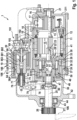
- a starting device 1 is shown in longitudinal section.
- This starting device 1 has a rotary drive 10 with a pole housing 11.
- An excitation winding 12 is arranged in the pole housing 11.
- the rotary drive 10 uses its armature 15 to drive an armature shaft 13 which carries a collector 16.
- Sliding contacts 17, which are often also referred to as carbon brushes, are located on the collector 16.
- the sliding contacts 17 are supplied via a power supply 18 or are supplied during operation.
- the armature shaft 13 is mounted with its commutator or collector-side end in a commutator bearing 21 of a commutator bearing cover 211.
- the armature shaft 13 has a structure which engages as a sun gear in the planetary gear with roller freewheel 50.
- a separate pinion can also be connected to the drive shaft 25 via a longitudinal toothing. This can be brought into engagement with the ring gear 27 of the internal combustion engine to be started by appropriately moving the output shaft 25.
- armature shaft 13 At an open end 29 of the armature shaft 13, there is a longitudinal toothing 30 on its outside, which forms a sun gear of a countershaft gear 28 designed as a planetary gear.
- This sun gear can also be designed separately and attached to a straight toothing of the armature shaft 13.
- Planetary gears 32 mesh with the sun gear, which in turn mesh with a fixed ring gear 33.
- An elongated drive bearing 36 is connected to the pole housing 11 in the axial direction and rests against an end surface 38 of the pole housing 11 with a collar 37.
- a sealing plate 39 is arranged between the drive bearing 36 and the pole housing 11.
- the drive bearing 36, the pole housing 11 and the collector bearing 21 are held together by tie rods 41.
- a roller bearing 44 for the output shaft 25 is arranged in a bore 43 in a bearing plate 42 of the drive bearing 36.
- the drive pinion 6 is located outside the bearing plate 42 in this embodiment.
- an intermediate bearing 46 which accommodates a roller bearing 47 in a central bore in which one part of a bush-shaped inner ring 48 of a freewheel 50 is mounted.
- an internal steep thread 51 into which a matching external steep thread 52 engages at an inner end of the output shaft 25.
- the external steep thread 52 is relatively long so that even with a large displacement of the output shaft 25 the internal steep thread 51 and the external steep thread 52 always remain in engagement with one another.
- a driver 54 of the freewheel 50 and the inner ring 48 there are cylindrical rollers 55 in the usual way, which run as clamping bodies on a wedge track of the inner ring 48.
- the driver 54 has several blind holes 57 on its end face facing the rotary drive 10, into which bolts 58 are pressed, which carry the planetary gears 32 of the planetary gear.
- a bearing 60 which can be designed as a roller bearing or plain bearing.
- the planetary gears 32 are also mounted by means of roller bearings, not further designated.
- the engagement relay 20 has a housing 62 which is open towards the drive bearing 36. It has a flat front surface 63 there, which in this case lies in the plane of the end surface 38 of the pole housing 11 and the annular collar 37 of the drive bearing 36.
- the drive bearing 36 has a flange-like housing extension 36A in the area of the engagement relay 20, through which several screws 64 penetrate and firmly connect the housing 62 of the engagement relay 20 to the drive bearing 36.
- the sealing plate 39 extends to the housing 62, rests against the flat front surface 63 of the housing 62 and extends to the outside of the extension 36A of the drive bearing 36.
- the following section deals with the engagement relay 20. It has a coil arrangement 66, which has a pull-in winding, the first pull-in winding 661, a second pull-in winding 662 and a so-called holding winding 663.
- a thrust armature 67 is guided within this coil arrangement 66.
- This thrust armature 67 or magnet armature has a central bore 68 in which a switching bolt 69 is mounted on the one hand, which is connected to a magnetic return protruding end carries a contact plate of the switching device 191.
- Two contacts are mounted in a relay housing cover 70, which are electrically connected to one another by the contact plate 192. One contact is a positive-side contact 193 and the other contact is a drive-side contact 194.
- a pressure bolt 71 is fixedly arranged in the bore 68 of the thrust armature 67, coaxial with the switching bolt 69. This projects into a displaceable plastic sleeve 73 provided with a longitudinal slot.
- a metal sleeve 75 is fastened to the outer end of the thrust armature 67, in which a meshing spring 76 is arranged.
- the pressure bolt 71 acts on an engagement lever 78, which is rotatably mounted in a bearing 79 fixed to the housing. At its other end, this engagement lever 78 is articulated to the output shaft 25 by means of a device 80. By moving the thrust armature 67, the engagement lever 78 is pivoted and thus the output shaft 25 is moved, whereby the drive pinion 26 is brought into engagement with the ring gear 27.
- the starting device 1 has an electric thrust drive 19.
- This thrust drive 19 has, as a previously unmentioned sub-unit, a so-called lifting magnet, which has the thrust armature 67 and whose position in the lifting magnet 100 is influenced by the coil arrangement 66 and in particular by the first pull-in winding 661, by the second pull-in winding 662 and by the holding winding 663 in its movement dynamics and its rest position.
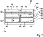
- Figure 2 shows schematically and by way of example a part of a longitudinal section of the coil arrangement 66.
- the linear drive 106 carries in its housing 62 a coil carrier 130, around which, ie around its tubular section 133, the three windings first pull-in winding 661, second pull-in winding 662 and holding winding 663 are arranged.
- the coil carrier 130 has a generally annular cross-section radially outside the tubular section 133 and between a flange 136 of the coil carrier at one end of the tubular section 133 and another flange 139 of the coil carrier 130, which represents a so-called winding volume 142 (total winding volume).
- the first pull-in winding 661 is arranged in a first annular volume of the winding volume 142.
- This first annular volume is represented in Figure 2 a cross-section 145.
- This Cross section 145 is a cross section through this first annular volume.
- the second pull-in winding 662 is arranged in a second annular volume, a winding volume, which is represented by the annular cross section 148 and which is part of the total winding volume of the coil carrier 130.
- This second annular volume of the second pull-in winding 662 preferably surrounds the first pull-in winding 661 with a part of this annular volume.
- This case is in Figure 2
- the annular volume of the second pull-in winding 662 preferably has a pot-shaped shape. This pot-shaped shape accordingly has a space in which no conductor of the second pull-in winding 662 is arranged.
- the first pull-in winding 661 is thus arranged immersed in this space.
- the second pull-in winding 662 thus surrounds the first pull-in winding 661 with a part of the annular volume.
- the holding winding 663 is arranged in a third annular volume of the winding volume 142 of the coil carrier 130.
- the holding winding 663 surrounds both the first pull-in winding 661 and the second pull-in winding 662.
- the cross section 151 represents this third annular volume mentioned.
- the winding volume 142 of the coil carrier 130 is thus made up of the winding volumes of the first pull-in winding 661, the second pull-in winding 662 and the holding winding 663.
- the coil carrier 130 particularly preferably has an annular wall 153 between the first pull-in winding 661 and the second pull-in winding 662.
- connections 154, 155 of the first pull-in winding 661 are led through one flange 139. It is also provided that the connections 156, 157 of the second pull-in winding 662 are also led through the flange 139. For the holding winding 663, it is also provided that connections 158, 159 are led through the flange 139. It is therefore particularly preferred that all connections 154 to 159 pass through one flange 139. By “passing through” the flange 139 is meant that, for example, one or more slots are made in the flange 139 through which all connections 154 to 159 pass.
- an insulating layer 162 is particularly preferably arranged between the pull-in winding 661 and the pull-in winding 662.
- a plastic clip is particularly preferably applied or an adhesive tape is wound onto the first insulating layer 661.
- an insulating layer 163 is particularly preferably arranged between the second pull-in winding and the holding winding 663, ie preferably glued or inserted onto the pull-in winding 662.
- FIG 3 is a circuit diagram of the above-mentioned starting device 1 in a first embodiment.
- the circuit is described in more detail below.
- the rotary drive 10 with its excitation winding 12 is connected to a negative connection 103.
- the rotary drive 10 can be electrically supplied with a positive pole + a starter battery 107 via a positive connection 106 and the switching device 191.
- the contact plate 192 of the switching device 191 is brought into contact with the contacts 193 (positive-side contact), 194 (drive-side contact), and the electrical contact is closed.
- This current supply via the contact plate 192 only takes place with the so-called second stage of current supply to the rotary drive 10.
- the structure described below and the method described are provided for switching the contact plate 192, which is part of the engagement relay 20.
- the structure is as follows:
- the engagement relay 20 has the coil arrangement 66 already mentioned with a first pull-in winding 661, a second pull-in winding 662 and a holding winding 663. In this first embodiment, all three windings have the same winding direction.
- the engagement relay 20 is switched on by a series relay 108.
- a linear drive 109 receives an inrush current via a control connection 110, which leads to a relay coil (not shown here) of the series relay 108 being energized. This energization of the relay coil of the series relay 108 leads to a series contact 112 being closed.
- This closing of the series contact 112 results in an electrical connection being made between the positive pole + of the starter battery 107 and a coil connection 114 of the coil arrangement 66.
- both the holding winding 663 and the second pull-in winding 662 and the first pull-in winding 661 are energized.
- the holding winding 663 is energized directly from the coil connection 114.
- the holding winding 663 is connected to the ground connection 103 via a ground connection 116.
- the second pull-in winding 662 is energized from the coil connection 114.
- the second pull-in winding 662 is electrically connected to the positive connection 106 of the rotary drive 10, so that on the negative side the current flowing through the pull-in winding 662 is led via the rotary drive 10 and the excitation winding 12 to the ground connection 103.
- An electrical connection also goes from the coil connection 114 to the first pull-in winding 661.
- this electrical connection initially runs via a Normally closed switch 120, which is closed, among other things, at the moment the engagement relay 20 is switched on by the series contact 112 or the series relay 108.
- the current flowing through the first pull-in winding 661 is also discharged in the direction of the positive connection 106.
- the first pull-in winding 661 is energized via the break switch 120 for a first period of time
- the second pull-in winding 662 is also energized during this first period of time
- the holding winding 663 is also energized during this first period of time.
- a magnetic field is thus built up in the coil arrangement 66, which causes the thrust armature 67 of the thrust drive 19 to begin to be drawn into the coil arrangement 66. This actuates the switching bolt 69, i.e.
- the switching bolt 69 is partially pushed out of the coil arrangement 66 by the thrust armature 67.
- the break switch 120 is still closed until the end of this first period of time.
- the rotary drive 10 is energized to a significant extent, primarily by the first pull-in winding 661, so that during this first period, the rotary drive 10 begins to rotate at a low power and thus sets the drive pinion 26 in rotation. Since the drive pinion 26 is already pushed towards the ring gear 27 of the internal combustion engine via the engagement lever 78, the drive pinion 26 thus moves at a very low speed, rotating in front of the teeth of the ring gear 27. At the end of the first period, the break switch 120 is opened.
- a rear side of the contact plate 192 keeps the break switch 120 closed during the first period.
- the electrically conductive rear side and thus the contact plate 192 can simultaneously be a break contact 122.
- This first period can last, for example, between 30 and 50 milliseconds from the start of the energization of the coil connection 114. In this example, it then takes a further 10 to 20 milliseconds in particular until the contact plate 192 forms a closed electrical contact with the positive-side contact 193 and the drive-side contact 194.
- the magnetic field of the pull-in winding 661 is reduced.
- This magnetic field of the first pull-in winding 661 accounts for approximately 15% of the total flux of the coil arrangement 66 during the first time period.
- Switching off the first pull-in winding results in mutual induction in the other two coils through which current flows, the second pull-in winding 662 and the holding winding 663. This leads to the current through the two coils, the second pull-in winding 662 and the holding winding 663, being increased slightly for a short time.
- the second time period is followed by a third time period, which begins at the moment in which the electrical contact is closed by means of the contact plate 192.
- the second pull-in winding 662 is practically short-circuited. This is because there is practically no voltage difference between the positive pole + of the starter battery 107 and the positive connection 106, and thus the second pull-in winding 662 has almost the same voltage on the positive side and the second pull-in winding 662 has almost the same voltage on the negative side. Even if the voltage should have a minimal difference, this means that the actual electromagnetic flux through the second pull-in winding 662 is no longer significant and therefore has no contribution to the further movement of the thrust armature 67. From the closing of the switching device 191, only the magnetic flux or the magnetic field of the holding winding 663 is essential for the further pull-in force of the thrust armature 67 into the coil arrangement 66.
- a starting device 1 for an internal combustion engine is thus disclosed, with a drive pinion 26 for meshing with a ring gear 27 of the internal combustion engine, with an electric rotary drive 10 and an electric thrust drive 19, wherein the rotary drive 10 serves to rotate the drive pinion 26 and the thrust drive 19 serves to push the drive pinion 26, and the electric thrust drive 19 has a lifting magnet 100 which has a thrust armature 67 which can be moved by a pull-in winding 661 within the pull-in winding 661 along a thrust armature axis 125.
- the lifting magnet 100 also has a holding winding 663 by which the thrust armature 67 can be held in the retracted state, wherein the thrust drive 19 also serves to actuate a switching device 191 by means of which the electric rotary drive 10 can be switched to a second drive stage.
- the second drive stage of the rotary drive 10 begins when the contact plate 192 makes electrical contact with the plus-side contact 193 and the drive-side contact 194 has closed.
- there is a second pull-in winding 662 which is connected in parallel to the first pull-in winding 661.
- the first pull-in winding 661 can be switched off by an NC switch 120, while a current path through the second pull-in winding 662 is closed.
- the switching device 191 in a switched-on position of the electric linear drive 19, the switching device 191 is closed and the break switch 120 of the switching device 191 is open. This is the case during the second time period. Accordingly, when the break switch 120 of the switching device 191 is open, a current path to the first pull-in winding 661 is open. It is provided that when the break switch is open, a current path through the second pull-in winding 662 is closed.
- the holding winding 663 is wound in the same direction as the second pull-in winding 662 and the first pull-in winding 661 is wound in the same direction as the second pull-in winding 662.
- a current path through the first pull-in winding 661 and a current path through the second pull-in winding 662 are closed by a series contact 112 or can be closed by a series contact 112.
- the holding winding 663, the first pull-in winding 661 and the second pull-in winding 662 are connected in parallel to each other.
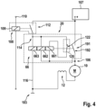
- FIG 4 A circuit of a starting device 1 is shown, which differs from the circuit according to Figure 3 only differs in that the first pull-in winding 661 has a different winding direction than the second pull-in winding 662 and the holding winding 663. All other details correspond to those in the Figure 3 It should be mentioned, however, that the negative feedback of the first pull-in winding 661 against the other two windings, pull-in winding 662 and holding winding 663, weakens their field. Here, for example, it takes 50 to 70 milliseconds (i.e. longer than in the embodiment of the Figure 3 ) until the break contact 122 is opened. After this opening, it takes a further 10 to 20 milliseconds until the switching device 191 is closed by the contact plate 192.
- a method for operating a starting device 1 for internal combustion engines is also provided, wherein a drive pinion 26 is provided for meshing with a ring gear 27 of the internal combustion engine.
- the electric rotary drive 10 and the electric linear drive 19 are used, with the rotary drive 10 serving to rotate the drive pinion 26 and the linear drive 19 serving to push the drive pinion 26.
- the electric linear drive 19 has a lifting magnet 100 which has a linear armature 67 which can be moved by a pull-in winding 661 within the pull-in winding 661.
- the lifting magnet 100 also has a holding winding 663 by which the linear armature 67 is held in the retracted state, with the linear drive 19 also serving to actuate a switching device 191 by means of which the electric rotary drive 10 is switched on.
- the holding winding 663, the second pull-in winding 662 and the first pull-in winding 661 which is connected magnetically in parallel with the latter, are switched on and then the first pull-in winding 661 is switched off by an NC switch 120, while a current path through the second pull-in winding 662 remains closed.
- the method provides in particular that the electric rotary drive 10 is energized via the second pull-in winding 662 and its inherent electrical resistance and thereby drives a drive pinion 26.
- the method provides in particular that by switching on and energizing the holding winding 663, the first pull-in winding 661 and the second pull-in winding 662, the thrust armature 67 is moved and an opener switch 120 is thereby opened. It is provided in particular that by opening the opener switch 120, a current path through the first pull-in winding 661 is opened. It is preferably provided that in the method, switching device 191 is closed and thereby a rotary drive-side connection of the second pull-in winding 662 is directly connected to a positive voltage potential of a starter battery.
- a series relay 108 can also be designed as an electronic switch with corresponding functionality using a semiconductor material.
- the series relay 108 would therefore be seen as a replacement switching element that has the described properties of the series relay 108.
- This also applies equally to the switching device 191 and the break switch, which after switching through (switching on the coil arrangement 66) of the series relay replacement switch or the series relay 108 and after a predetermined time (timer or computer switching unit), the first pull-in winding 661 is energized by means of an electronic replacement switch (semiconductor switch) as a break switch 120.
- an electronic replacement switch semiconductor switch
- an electronic replacement switch semiconductor switch
Landscapes
- Engineering & Computer Science (AREA)
- General Engineering & Computer Science (AREA)
- Mechanical Engineering (AREA)
- Chemical & Material Sciences (AREA)
- Combustion & Propulsion (AREA)
- Physics & Mathematics (AREA)
- Electromagnetism (AREA)
- Power Engineering (AREA)
- Connection Of Motors, Electrical Generators, Mechanical Devices, And The Like (AREA)
Description
- Bei Nutzkraftwagen werden Starter verwendet, die eine verhältnismäßig große Leistung aufweisen. Es gelten hohe Anforderungen an die Lebensdauer von derartigen Startern. Dies bedeutet insbesondere, dass ein Verschleiß am Ritzel bzw. Einrückritzel des Starters und am Zahnkranz der Brennkraftmaschine gering gehalten werden soll bzw. muss. Um dies zu erreichen, werden meist elektrisch zweistufige Einspursysteme verwendet.
- Der Grund hierfür ist, dass bei einstufigen Starter-Systemen beim Einspuren des Ritzels in den Zahnkranz ein überwiegender Anteil von sogenannten Zahn-auf-Zahn-Stellungen auftritt, die systembedingt dann mit einer großen axialen Kraft des Einrückrelais, oder sofern verbaut, der dazwischen befindlichen Einspurfeder und in Verbindung mit einem großen Andrehmoment aufgelöst werden. Das große Andrehmoment führt zu einer großen tangentialen Kraft an den Zähnen von Ritzel und Zahnkranz. All dies bedingt einen relativen hohen mechanischen Verschleiß. Aus diesem Grund werden die oben erwähnten zweistufigen Einspursysteme verwendet. Dabei wird beispielsweise während des Vorspurens des Ritzels dieses auch verdreht. Hierzu fließt ein relativ geringer Strom durch den elektrischen Startermotor. In dieser ersten Stufe des Einspurens wird somit die Wahrscheinlichkeit erhöht, dass die Ritzelzähne in die Lücken des Zahnkranzes einspuren können.
- Um einen geringen Verschleiß an Ritzel und Zahnkranz zu erreichen und dennoch eine elektrisch und thermisch geeignete und zuverlässige Auslegung erreichen zu können, wird seit Jahren in verschiedenen Startertypen, die von der Robert Bosch GmbH für Nutzfahrzeuge vertrieben werden, eine so genannte Zweikammer-Wicklung eingesetzt. Zu den erwähnten Startertypen gehören die Typen HEF95-L, HXF95-L, HEF 109-M, HEF 109-MP, HEF109-L sowie deren Parallelstarter-Versionen HEP109. Bei diesen Startertypen befindet sich im Einrückrelais eine Wicklungsanordnung, wie sie aus der Offenlegungsschrift der deutschen Patentanmeldung
DE 10 2004 032 373 A1 bekannt ist. Die aus diesem Dokument bekannte Wicklungsanordnung ist die von Fachleuten so bezeichnete Zweikammer-Wicklung. Eine Einzugswicklung wird zu Beginn des Startvorgangs bestromt und leitet dabei den so genannten Verdrehstrom während des Einspurvorgangs (erste Stufe) zum Startermotor durch, der dann leicht in Drehung versetzt wird. Mittels eines so genannten Öffnerkontakts wird diese Einzugswicklung dann abgeschaltet, wenn der so genannte Hauptstromschalter - manchmal auch als Kontaktplatte bezeichnet - durch das Fortschreiten des Magnetankers im Einrückrelais vom Öffnerkontakt abgehoben wird. Des Weiteren hat die Zweikammer-Wicklung eine Haltewicklung, welche zwar die eigentlichen magnetischen Einzugskräfte aufbringt, aber nach Abschalten der Einzugswicklung den Magnetanker auch sicher in der Arbeitsstellung hält. Der Hauptteil der magnetischen Einzugskräfte wird von der Haltewicklung erzeugt (ca. 6.000 Amperewindungen), die Magnetkraft der Einzugswicklung ist mit ca. 1000 Amperewindungen vergleichsweise gering. - Gegenüber einer früher gebräuchlichen Wicklungsanordnung mit einer so genannten Mäanderwicklung - man vergleiche beispielsweise mit der deutschen Offenlegungsschrift
DE 198 14 504 A1 - weist die Version mit Einzugs- und Haltewicklung zwar deutliche Funktionsvorteile auf, dennoch ist die Haltewicklung weiter optimierbar. So sind die magnetischen Zugkräfte, bedingt durch die Auslegung, begrenzt. Es ist eine Kompromisslösung zwischen maximaler magnetischer Zugkraft und thermischer Stabilität der Wicklung, so dass die maximal zulässige Einschaltdauer begrenzt ist. Eine weitere Optimierung der erreichbaren dynamischen Einspurtiefe bzw. der Temperaturfunktionsgrenze würde mit einer Reduzierung der thermischen Stabilität des Wicklungssystems einhergehen. Die dynamische Einspurtiefe ist dabei die Tiefe, die das Ritzel bzw. Einrückritzel in der Verzahnung des Zahnkranzes bis zum Schließen des Hauptstromschalters erreicht. - Insbesondere dann, wenn bei Startvorrichtungen der Elektromotor für höhere Leistungen vergrößert ist, verlängert sich zwar die mögliche Einschaltdauer des Elektromotors gegenüber weniger leistungsstarken Motoren um z. B. 50 % bis 80 %; allerdings ist die Temperaturbelastbarkeit an unterschiedlichen Brennkraftmaschinen unterschiedlich hoch und kommt daher bei manchen Kombinationen an die Grenzen bzw. stellt die Wicklungsanordnung im Einrückrelais das begrenzende Element dar, so dass deren maximal zulässige Betriebstemperatur erreicht wird.
- Aus der Offenlegungsschrift
DE 37 37 430 A1 ist eine Startvorrichtung bekannt, die ein Einrückrelais für ein in einen Zahnkranz einzuspurendes Ritzel aufweist. Dieses Einrückrelais weist hierzu drei Wicklungen auf. Eine als Spulenabschnitt bezeichnete Wicklung, welche mit einer Diode in Reihe angeordnet ist, erfährt nach dem Bestromen durch einen Hilfsschalter erst wieder mit einem Schließen eines Hauptstromkontakts eine geänderte anliegende Spannung. Alle drei Wicklungen bestromen somit den sich dadurch bis zu diesem Ereignis drehenden Elektromotor. - Aus der Offenlegungsschrift
WO 2013/093365 A1 ist eine Startvorrichtung mit einem Ausführungsbeispiel bekannt, das einen Hubmagneten aufweist, der dazu dient, ein Ritzel in einen Zahnkranz einzuspuren. Durch einen weiteren Hubmagneten wird eine Kontaktplatte durch eine Drehung mit einer Achse senkrecht zur Hubachse des anderen Hubmagneten an einen Zwischenanschluss kontaktiert und dadurch ein Betrag zum Bestromen des Motors zum Antrieb des Zahnkranzes geliefert.EP 2 795 650 B1 beschreibt eine weitere Startvorrichtung für eine Brennkraftmaschine. - Ein Gesichtspunkt der Erfindung ist daher eine Optimierung der Kenngrößen, welche mit den magnetischen Zugkräften im Einrückrelais und der maximal möglichen Einschaltdauer zusammenhängen. Dabei muss berücksichtigt werden, dass das Andrehverhalten des Elektromotors bzw. des Startermotors, d. h. seine Kennlinie beim Anschleppen der Brennkraftmaschine über den Zahnkranz, möglichst sinnvoll ist. Zudem soll der Materialeinsatz optimiert werden, so dass der Aufwand beispielsweise an Kupferdraht für die Wicklungsanordnung möglichst optimiert ist.
- Gemäß einem ersten Gesichtspunkt ist vorgesehen, dass die für das Verfahren vorgesehene Startvorrichtung mit einem Antriebsritzel zum Einspuren in einen Zahnkranz einer Brennkraftmaschine derart ausgestaltet ist, dass dieses durch einen elektrischen Drehantrieb drehbar und durch einen elektrischen Schubantrieb axial verschiebbar ist. Der elektrische Schubantrieb weist einen Hubmagneten auf, der einen Schubanker hat, der durch eine Kombination von verschiedenen Wicklungen innerhalb dieser Wicklungen bewegbar ist. In diesem Fall sind Einzugswicklungen verbaut, die nur während des Einzugsvorganges bestromt werden. Zudem weist der Schubantrieb eine Haltewicklung auf, durch die der Schubanker in einem eingezogenen Zustand gehalten werden kann. Der Schubantrieb dient auch zum Betätigen einer Schaltvorrichtung, mittels derer der elektrische Drehantrieb einschaltbar ist. Es ist dabei vorgesehen, dass neben der einen, der ersten Einzugswicklung, eine zweite Einzugswicklung vorhanden ist, die zu der ersten Einzugswicklung parallelgeschaltet ist.
- In dem Schubantrieb sind somit drei Wicklungen vorhanden. Dies führt dazu, dass für eine erforderliche große Zugkraft für den Einzugsvorgang des Schubankers und das Schieben des Antriebsritzels eine Einzugswicklung und eine Haltewicklung vorhanden sind, die zueinander parallelgeschaltet und gleichsinnig parallel wirkend sind. Während einer ersten Phase im Betrieb der Startvorrichtung fließt der recht hohe Verdrehstrom für den elektrischen Drehantrieb durch eine verhältnismäßig niederohmige Einzugswicklung im Schubantrieb. Weil diese erste Einzugswicklung im Schubantrieb eine verhältnismäßig geringe magnetische Wirkung aufweist, kann diese der Haltewicklung und der anderen, der zweiten Einzugswicklung, mitgekoppelt oder gegengekoppelt geschaltet sein, um die Dynamik des Schubantriebs und damit der Bewegung des Schubankers im Schubantrieb zu beeinflussen und je nach Auslegung zu optimieren. Im weiteren Verlauf des Schubantriebs wird ein Öffnerschalter betätigt, d. h. geöffnet, so dass ein Verdrehstrom nach einem ersten Zeitabschnitt von beispielsweise ca. 50 Millisekunden bis 70 Millisekunden abgeschaltet wird bzw. abgeschaltet werden kann und so eine magnetische Zugkraft auf den Schubanker nur noch von der zweiten Einzugswicklung und der Haltewicklung erzeugt wird bzw. erzeugt werden kann.
- Nach einem darauffolgenden zweiten Zeitabschnitt wird durch die Anordnung ermöglicht, dass die zweite Einzugswicklung elektrisch abgeschaltet wird. Dieser zweite Zeitabschnitt dauert beispiels- und typischerweise ca. 10 Millisekunden bis 20 Millisekunden. Das Abschalten der zweiten Einzugswicklung ist faktisch ein Kurzschluss der zweiten Einzugswicklung, da durch das Schließen der Hauptstromkontakte ein Wicklungsanfang der zweiten Einzugswicklung und ein Wicklungsende der zweiten Einzugswicklung auf fast gleichem elektrischen Potential liegen und so zwar ein minimaler Strom durch die zweite Einzugswicklung fließt, dieser aber tatsächlich keinen praktischen Nutzen erzielt. Die zweite Einzugswicklung ist somit magnetisch fast nicht mehr wirksam. Die Haltekraft für den Schubanker wird somit praktisch nur noch von der Haltewicklung erzeugt. Im Vergleich mit bisher bekannten Ausführungen derartiger Schubantriebe bzw. Starterrelais fließt in dieser Situation durch die Haltewicklung jedoch ein deutlich verringerter elektrischer Strom. Dieser kann beispielsweise um ca. 40% abgesenkt sein. Dies ermöglicht in der Folge eine verlängerte maximal mögliche Einschaltdauer des Schubantriebs, da aufgrund des verringerten Stroms auch die Erwärmung des gesamten Schubantriebs deutlich verringert ist. Der Verwender einer derartigen Startvorrichtung hat dadurch die Möglichkeit, das volle thermische Potential des elektrischen Drehantriebs auszuschöpfen.
- Für das Abschalten des Schubantriebs gilt als eine Auslegungsbedingung, dass eine Windungszahl der Haltewicklung ungefähr gleich der Windungszahl der zweiten Einzugswicklung ist. Andernfalls lässt sich ein derartiger Schubantrieb zwar einschalten, aber nicht mehr abschalten.
- Durch eine Optimierung der verschiedenen Parameter der Wicklungen lässt sich ein Wicklungssystem ermöglichen, das folgende Eigenschaften aufweist:
Verglichen mit bekannten Systemen mit einer Zweikammer-Wicklung ergibt sich mit einem derartig optimierten Schubantrieb eine erhöhte Temperaturgrenze, bei der die Funktion insgesamt zuverlässig erreicht wird. Die Temperaturgrenze lässt sich durch ein derartiges optimiertes System um ca. 10% erhöhen. - Mit diesem neuen System lässt sich eine Einschaltdauer deutlich verlängern, da eine Verlustleistung der Haltewicklung gegenüber bisherigen Systemen mit Zweikammer-Wicklung reduziert ist. Die mögliche verlängerte Einschaltdauer ist je nach Betriebsart bis ca. 60 % länger als bisher. Es kann die bisherige Charakteristik des Verdrehstroms, d. h. beispielsweise die Stromhöhe und die Einschaltdauer während der ersten Stufe, beibehalten werden. Falls derartige Schubantriebe bei bisher bekannten Startvorrichtungen Anwendung finden, bspw. in Kombination mit den bereits bekannten Startvorrichtungen HEF109-M bzw. HEF109-L, wird ein sogenanntes Andrehverhalten und somit eine Lebensdauer der Starter bzw. Startvorrichtungen nicht negativ beeinflusst.
- Gegenüber einem bisherigen System mit Zweikammer-Wicklung wird ein sogenanntes KupferEinsatzgewicht um ca. 15% Kupfer reduziert. Das Kupfereinsatzgewicht entspricht der Summe der Kupfermasse in der Haltewicklung und der zweiten Einzugswicklung. Die erste Einzugswicklung ist beispielsweise aus einer speziellen Widerstandslegierung gefertigt und ist daher bei dem Kupfereinsatzgewicht nicht berücksichtigt.
- Es ist vorgesehen, dass in einer Einschaltstellung des elektrischen Schubantriebs ein Hauptstromschalter der Schalteinrichtungen geschlossen und der Öffnerschalter der Schalteinrichtung geöffnet ist. Dies hat den Vorteil, dass der elektrische Drehantrieb zwar kurzzeitig während des Geschlossenseins des Öffnerschalters und gleichzeitiger Bestromung von einem nennenswerten Strom durchflossen wird, wodurch der Drehantrieb das Antriebsritzel zum Drehen bringt. Das Drehen des Antriebsritzels ist während dieser Phase nicht zu stark, so dass während des gleichzeitigen Bestromens der Haltewicklung und der zweiten Einzugswicklung der Schubantrieb gleichzeitig das Antriebsritzel zu dem Zahnkranz der Brennkraftmaschine schiebt und im Zusammenwirken der translatorischen und rotatorischen Bewegung des Antriebsritzels mit hoher Wahrscheinlichkeit eine Position gegenüber dem Zahnkranz erreicht wird, sodass ein Zahn der Verzahnung des Antriebsritzels in eine Lücke der Verzahnung des Zahnkranzes eindringt. Dadurch wird letztlich vermieden, dass ein an der Verzahnung des Zahnkranzes anliegendes Antriebsritzel mit hoher Andrehdynamik und infolgedessen mit hoher Drehzahl an der Verzahnung des Zahnkranzes stirnseitig entlang dreht, dabei zwar immer wieder geringfügig mit den Zähnen des Antriebsritzels in die Lücken der Verzahnung des Zahnkranzes eindringt, aber auch immer wieder aus diesen Lücken der Verzahnung des Zahnkranzes herausgedrückt wird. Dieses Herausgedrückt-werden und immer wieder geringfügiges Eindringen in die Verzahnung des Zahnkranzes führt zu geräuschvollem Rattern, welches ein hörbares Zeichen dafür ist, dass sich die Verzahnung des Antriebsritzels und die Verzahnung des Zahnkranzes gegenseitig erheblich verschleißen. Auch wenn dieser Vorgang zum Teil nur Bruchteile von Sekunden andauert, wird über die Nutzungsdauer des Startsystems ein unverhältnismäßig großer Verschleiß erzeugt. Gemäß einem weiteren Aspekt der Vorrichtung ist vorgesehen, dass bei geöffnetem Öffnerschalter der Schalteinrichtung ein Strompfad zur ersten Einzugswicklung geöffnet ist.
- Es ist dabei vorgesehen, dass bei geöffnetem Öffnerschalter ein Strompfad durch die zweite Einzugswicklung geschlossen ist. Dies hat den Vorteil, dass bei gleichsinniger Wicklung von Haltewicklung und zweiter Einzugswicklung durch diese beiden Wicklungen das weitere Eindringen des Antriebsritzels in den Zahnkranz der Brennkraftmaschine unterstützt wird.
- Gemäß einem weiteren Gesichtspunkt der Erfindung ist vorgesehen, dass die Haltewicklung im gleichen Sinn wie die zweite Einzugswicklung gewickelt ist und die erste Einzugswicklung ebenfalls im gleichen Sinn gewickelt ist, d. h. alle drei Wicklungen sind im gleichen Wicklungssinn gewickelt. Daraus ergibt sich beim Abschalten der ersten Einzugswicklung der Effekt, dass die Summe des gesamten Magnetfelds der drei Wicklungen schwächer wird. Dies hat den Vorteil, dass letztlich die Dynamik dieses Schubantriebs und hier insbesondere des Schubankers an die geänderte Situation angepasst wird. D. h., dass der sich nun in Bewegung befindliche Schubanker nicht mehr aus der vollständigen Trägheit (Ruhezustand) losbewegt werden muss und somit auch mit weniger Schubenergie weiterbewegt werden kann. D. h. zum Beispiel, dass bei einer derartigen Anordnung erreicht wird, dass ein Anschlag des Schubankers am magnetischen Rückschluss des Schubantriebs weniger stark und somit die Geräuscherzeugung geringer ist.
- Beim Abschalten der ersten Einzugswicklung, die ca. 15 % des gesamten Flusses ausmachen kann, ergibt sich eine Gegeninduktion in den zwei anderen stromdurchflossenen Spulen Haltewicklung und zweiter Einzugswicklung. Dies bedeutet, dass ein Strom durch die beiden Spulen, Haltewicklung und zweiter Einzugswicklung aufgrund des zusammenbrechenden Magnetfelds in der ersten Einzugswicklung kurzfristig etwas erhöht wird. Weitere Vorteile sind die erhöhte Temperaturfunktionsgrenze, da der magnetische Schubantrieb auch bei hohen Temperaturen der Kupferwicklungen zusätzlich durch die erste Einzugswicklung magnetisch unterstützt wird, allerdings wird dadurch auch die Verdrehzeit des Ritzels verkürzt, wodurch das Einspurverhalten je nach Andrehverhalten des Elektromotorteiles optimiert werden kann.
- Gemäß einer weiteren Ausgestaltung der Erfindung ist vorgesehen, dass die erste Einzugswicklung im ungleichen Sinn wie die zweite Einzugswicklung und auch im ungleichen Sinn zur Haltewicklung gewickelt ist. Dies hat den Vorteil, dass durch das sich abbauende Magnetfeld der ersten Einzugswicklung die Bilanz der gesamten magnetischen Durchflutung als Summe der Durchflutung der zweiten Einzugswicklung und Haltewicklung verstärkt, also zusätzlich beschleunigt, nachdem der Verdreh- und Einspurvorgang mit hoher Wahrscheinlichkeit abgeschlossen ist. Je nach Andrehverhalten des Elektromotorteiles kann diese Verschaltung Vorteile in der Abstimmung "Dauer des Einspurvorgangs und nachfolgendem Durchzugsverhalten" bieten.
- Bei der Ausführung mit drei Teilwicklungen ist die Aufteilung in etwa so, dass die Haltewicklung ca. 2.800 Amperewindungen aufweist und somit ca. 45% der Einzugskraft und 100% der Haltekraft aufbringt. Die erste Einzugswicklung weist ca. 1.000 Amperewindungen auf und bremst die Einzugsfunktion der zweiten Einzugswicklung und der Haltewicklung in den ersten ca. 70ms um 1.000 Amperewindungen ab und liefert den Verdrehstrom. Die zweite Einzugswicklung weist ca. 3.300 Amperewindungen auf und liefert ca. 55% der Einzugskraft.
- Einer der Hauptvorteile, sowohl mit einer ersten Einzugswicklung, die im gleichen Sinn oder im Gegensinn gewickelt ist, ergibt sich dadurch, dass letztlich drei verschiedene Wicklungen bei der Erzeugung der Schubkraft beteiligt sind und letztlich stufenweise abgeschaltet werden. Dieses stufenweise Abschalten führt dazu, dass im Hinblick auf den Bewegungszustand des Schubankers bedarfsgereicht die einzelnen Einzugswicklungen nacheinander ausgeschaltet werden bzw. praktisch wirkungslos sind. Dies ermöglicht letztlich eine an den Bedarf angepasste, insgesamt verringerte Dimensionierung der Haltewicklung, d. h. diese Haltewicklung, welche die Haltekraft während der Durchdrehphase des Verbrennungsmotors erzeugt, benötigt, verglichen mit einer zuvor verwendeten Haltewicklung, weniger als die Hälfte der ursprünglichen Masse, d. h. der Kupfermasse, die bestromt wird. Die dennoch vorgesehene zweite Einzugswicklung kann mit reduzierter Kupfermasse ausgeführt werden, da diese nur kurz während des Einzug Vorgangs bestromt wird. Ein weiterer Gesichtspunkt der Erfindung ist, dass der Schubantrieb einen Spulenträger aufweist, wobei die erste Einzugswicklung in einem ersten ringförmigen Querschnitt eines Wickelvolumens des Spulenträgers angeordnet ist und die zweite Einzugswicklung in einem zweiten ringförmigen Querschnitt eines Wickelvolumens des Spulenträgers angeordnet ist und dabei bevorzugt mit einem Teil des ringförmigen Querschnitts die erste Einzugswicklung umgibt, wobei die Haltewicklung in einem dritten ringförmigen Querschnitt des Wickelvolumens des Spulenträgers angeordnet ist und dabei sowohl die erste Einzugswicklung, als auch die zweite Einzugswicklung umgibt. Dies hat den Vorteil, dass die Wicklung, welche während des gesamten Einspur- und Andrehprozesses der Startvorrichtung am längsten bestromt ist, nach dem effektiven Abschalten der zweiten Einzugswicklung diese als Wärmesenke verwenden kann und gleichzeitig auch noch über das Gehäuse des Schubantriebs Wärme abführen kann.
- Weitere Vorteile ergeben sich für das erfindungsgemäße Verfahren. Des Weiteren ergeben sich weitere Vorteile und zweckmäßige Ausführungen der Beschreibung und den Zeichnungen.
- Es zeigen:
- Figur 1
- eine Längsschnittdarstellung einer Startvorrichtung,
- Figur 2
- eine prinzipielle Darstellung eines Längsschnitts eines Spulenträgers des Schubantriebs mit der Lage einer ersten Einzugswicklung, einer zweiten Einzugswicklung und einer Haltewicklung,
- Figur 3
- ein erstes Schaltbild der Startvorrichtung aus
Figur 1 , - Figur 4
- ein zweites Schaltbild eines alternativen Ausführungsbeispiels auf Grundlage des ersten Ausführungsbeispiels.
- Gleiche Bezugszeichen bezeichnen gleiche Bauteile.
- In
Figur 1 ist eine Startvorrichtung 1 im Längsschnitt dargestellt. Diese Startvorrichtung 1 hat einen Drehantrieb 10 mit einem Polgehäuse 11. In dem Polgehäuse 11 ist eine Erregerwicklung 12 angeordnet. Der Drehantrieb 10 treibt mit seinem Anker 15 eine Ankerwelle 13 an, die einen Kollektor 16 trägt. An dem Kollektor 16 liegen Gleitkontakte 17 an, die oftmals auch als Kohlebürsten bezeichnet werden. Die Gleitkontakte 17 werden über eine Stromzuführung 18 versorgt bzw. im Betrieb versorgt werden. Oberhalb des Polgehäuses 11 sitzt ein Einrückrelais, das einen Schubantrieb 19 und eine Schaltvorrichtung 191 aufweist. Die Ankerwelle 13 ist mit ihrem kommutator- bzw. kollektorseitigen Ende in einem Kommutatorlager 21 eines Kommutatorlagerdeckels 211 gelagert. An ihrem anderen Ende weist die Ankerwelle 13 eine Konstruktion auf, die als Sonnenrad in das Planetengetriebe mit Rollenfreilauf 50 eingreift. In dieses ragt ein Steilgewinde der Abtriebswelle 25, die an ihrem äußeren anderen Ende ein Antriebsritzel 26 aufweist. Als Variante kann auch ein separates Ritzel über eine Längsverzahnung mit der Antriebswelle 25 verbunden sein. Dieses kann durch entsprechende Verschiebung der Abtriebswelle 25 mit dem Zahnkranz 27 der zu startenden Brennkraftmaschine in Eingriff gebracht werden. - An einem offenen Ende 29 der Ankerwelle 13 findet sich auf ihrer Außenseite eine Längsverzahnung 30, welche ein Sonnenrad eines als Planetenradgetriebe ausgebildeten Vorgelegegetriebes 28 bildet. Dieses Sonnenrad kann auch separat ausgeführt und auf einer Geradverzahnung der Ankerwelle 13 aufgesteckt sein. Mit dem Sonnenrad kämmen Planetenräder 32, die wiederum mit einem feststehenden Hohlrad 33 in Eingriff stehen.
- An das Polgehäuse 11 schließt sich in axialer Richtung ein langgestrecktes Antriebslager 36 an, das mit einem Bund 37 an einer Endfläche 38 des Polgehäuses 11 anliegt. Zwischen dem Antriebslager 36 und dem Polgehäuse 11 ist eine Dichtplatte 39 angeordnet. Das Antriebslager 36, das Polgehäuse 11 und das Kollektorlager 21 sind durch Zuganker 41 zusammengehalten. In einem Lagerschild 42 des Antriebslagers 36 ist in einer Bohrung 43 ein Wälzlager 44 für die Abtriebswelle 25 angeordnet. Das Antriebsritzel 6 befindet sich in diesem Ausführungsbeispiel außerhalb des Lagerschilds 42.
- Innerhalb des Antriebslagers 36 befindet sich ein Zwischenlager 46, welches in einer mittigen Bohrung ein Wälzlager 47 aufnimmt, in welchem der eine Teil eines buchsenförmigen Innenrings 48 eines Freilaufs 50 gelagert ist. An einer Innenseite des Innenrings 48 ist ein Innensteilgewinde 51 ausgebildet, in welches ein dazu passendes Außensteilgewinde 52 an einem inneren Ende der Abtriebswelle 25 eingreift. Das Außensteilgewinde 52 ist verhältnismäßig lang ausgebildet, sodass auch bei einer großen Verschiebung der Abtriebswelle 25 das Innensteilgewinde 51 und das Außensteilgewinde 52 stets miteinander in Eingriff bleiben.
- Zwischen einem Mitnehmer 54 des Freilaufs 50 und dem Innenring 48 befinden sich in üblicher Weise Zylinderrollen 55, die als Klemmkörper auf einer Keilbahn des Innenrings 48 laufen. Der Mitnehmer 54 weist an seiner dem Drehantrieb 10 zugewandten Stirnseite mehrere Sackbohrungen 57 auf, in welche Bolzen 58 eingepresst sind, welche die Planetenräder 32 des Planetengetriebes tragen. Zwischen dem Innenring 48 und dem Außenring, welcher der Mitnehmer 54 ist, befindet sich ein Lager 60, welches als Wälzlager oder Gleitlager ausgebildet sein kann. Die Planetenräder 32 sind ebenfalls mittels nicht weiter bezeichneten Wälzlagern gelagert.
- Das Einrückrelais 20 weist ein Gehäuse 62 auf, welches zum Antriebslager 36 hin offen ist. Es weist dort eine ebene Stirnfläche 63 auf, die in diesem Fall in der Ebene der Endfläche 38 des Polgehäuses 11 und des ringförmigen Bundes 37 des Antriebslagers 36 liegt. Das Antriebslager 36 hat im Bereich des Einrückrelais 20 eine flanschartige Gehäuseerweiterung 36A, durch welche mehrere Schrauben 64 hindurchdringen und das Gehäuse 62 des Einrückrelais 20 mit dem Antriebslager 36 fest verbinden. Die Dichtplatte 39 erstreckt sich bis zum Gehäuse 62, liegt an der ebenen Stirnfläche 63 des Gehäuses 62 an und erstreckt sich bis zur Außenseite der Erweiterung 36A des Antriebslagers 36.
- Nachfolgend wird auf das Einrückrelais 20 eingegangen. Es hat eine Spulenanordnung 66, die eine Einzugswicklung, die erste Einzugswicklung 661, eine zweite Einzugswicklung 662 und eine sogenannte Haltewicklung 663 aufweist. Innerhalb dieser Spulenanordnung 66 ist ein Schubanker 67 geführt. Dieser Schubanker 67 bzw. Magnetanker hat eine mittige Bohrung 68, in der einerseits ein Schaltbolzen 69 gelagert ist, welcher an seinem aus einem magnetischen Rückschluss herausragenden Ende eine Kontaktplatte der Schaltvorrichtung 191 trägt. In einem Relaisgehäusedeckel 70 sind zwei Kontakte gelagert, die durch die Kontaktplatte 192 miteinander elektrisch leitfähig verbunden werden. Der eine Kontakt ist ein plusseitiger Kontakt 193 und der andere Kontakt ist ein antriebsseitiger Kontakt 194. Achsgleich zum Schaltbolzen 69 ist in der Bohrung 68 des Schubankers 67 ein Druckbolzen 71 fest angeordnet. Dieser ragt in eine verschiebbare, mit einem Längsschlitz versehene Kunststoffhülse 73 hinein. Am außenliegenden Ende des Schubankers 67 ist eine Metallhülse 75 befestigt, in welcher eine Einspurfeder 76 angeordnet ist. Der Druckbolzen 71 wirkt auf einen Einrückhebel 78 ein, welcher in einem gehäusefesten Lager 79 drehbar gelagert ist. Mit seinem anderen Ende ist dieser Einrückhebel 78 mittels einer Vorrichtung 80 an der Abtriebswelle 25 angelenkt. Durch Verschieben des Schubankers 67 wird der Einrückhebel 78 verschwenkt und damit die Abtriebswelle 25 verschoben, wodurch das Antriebsritzel 26 mit dem Zahnkranz 27 in Eingriff gebracht wird.
- Wie bereits erwähnt, weist die Startvorrichtung 1 einen elektrischen Schubantrieb 19 auf. Dieser Schubantrieb 19 hat als bisher nicht erwähnte Untereinheit einen sogenannten Hubmagneten, der den Schubanker 67 aufweist und dessen Lage im Hubmagneten 100 durch die Spulenanordnung 66 und hierbei insbesondere durch die erste Einzugswicklung 661, durch die zweite Einzugswicklung 662 und durch die Haltewicklung 663 in seiner Bewegungsdynamik und seiner Ruhelage beeinflusst wird.
-
Figur 2 zeigt schematisch und beispielhaft einen Teil eines Längsschnitts der Spulenanordnung 66. Der Schubantrieb 106 trägt in seinem Gehäuse 62 einen Spulenträger 130, um den herum, d. h. um dessen rohrförmigen Abschnitt 133, die drei Wicklungen erste Einzugswicklung 661, zweite Einzugswicklung 662 und Haltewicklung 663 angeordnet sind. - Der Spulenträger 130 hat radial außerhalb des rohrförmigen Abschnitts 133 und zwischen einem Flansch 136 des Spulenträgers an einem Ende des rohrförmigen Abschnitts 133 und einem anderen Flansch 139 des Spulenträgers 130 einen insgesamt ringförmigen Querschnitt, der für ein sogenanntes Wickelvolumen 142 (Gesamtwickelvolumen) steht. Die erste Einzugswicklung 661 ist dabei in einem ersten ringförmigen Volumen des Wickelvolumens 142 angeordnet. Für dieses erste ringförmige Volumen steht in
Figur 2 ein Querschnitt 145. Dieser Querschnitt 145 ist ein Querschnitt durch dieses erste ringförmige Volumen. Die zweite Einzugswicklung 662 ist in einem zweiten ringförmigen Volumen, einem Wickelvolumen, für das der ringförmigen Querschnitt 148 steht und der ein Teil des Gesamtwickelvolumens des Spulenträgers 130 ist, angeordnet. Dieses zweite ringförmige Volumen der zweiten Einzugswicklung 662 umgibt dabei bevorzugt mit einem Teil dieses ringförmigen Volumens die erste Einzugswicklung 661. Dieser Fall ist inFigur 2 dargestellt. Das heißt, dass das ringförmige Volumen der zweiten Einzugswicklung 662 bevorzugt eine topfförmige Gestalt aufweist. Diese topfförmige Gestalt weist demnach einen Raum auf, in dem kein Leiter der zweiten Einzugswicklung 662 angeordnet ist. In diesem Raum eingetaucht ist somit die erste Einzugswicklung 661 angeordnet. Die zweite Einzugswicklung 662 umgibt somit mit einem Teil des ringförmigen Volumens die erste Einzugswicklung 661. Die Haltewicklung 663 ist in einem dritten ringförmigen Volumen des Wickelvolumens 142 des Spulenträgers 130 angeordnet. Die Haltewicklung 663 umgibt dabei sowohl die erste Einzugswicklung 661, als auch die zweite Einzugswicklung 662. Für dieses erwähnte dritte ringförmige Volumen steht der Querschnitt 151. Das Wickelvolumen 142 des Spulenträgers 130 setzt sich somit aus den Wickelvolumen der ersten Einzugswicklung 661, der zweiten Einzugswicklung 662 und der Haltewicklung 663 zusammen. Besonders bevorzugt weist der Spulenträger 130 zwischen der ersten Einzugswicklung 661 und der zweiten Einzugswicklung 662 eine ringförmige Wand 153 auf. Es ist dabei auch vorgesehen, dass die Anschlüsse 154, 155 der ersten Einzugswicklung 661 durch den einen Flansch 139 hindurchgeführt sind. Ebenso gilt, dass vorgesehen ist, dass die Anschlüsse 156, 157 der zweiten Einzugswicklung 662 ebenfalls durch den Flansch 139 hindurchgeführt sind. Auch für die Haltewicklung 663 ist vorgesehen, dass Anschlüsse 158, 159 durch den Flansch 139 hindurchgeführt sind. Es treten somit besonders bevorzugt alle Anschlüsse 154 bis 159 durch den einen Flansch 139 hindurch. Unter "Hindurchtreten" durch den Flansch 139 ist gemeint, dass beispielsweise in dem Flansch 139 ein oder mehrere Schlitze eingebracht sind, durch die alle Anschlüsse 154 bis 159 treten. Des Weiteren ist besonders bevorzugt zwischen der Einzugswicklung 661 und der Einzugswicklung 662 eine Isolationsschicht 162 angeordnet. Hierzu ist besonders bevorzugt ein Kunststoffclip aufgebracht oder ein Klebeband auf die erste Isolationsschicht 661 aufgewickelt. Des Weiteren ist besonders bevorzugt zwischen der zweiten Einzugswicklung und der Haltewicklung 663 eine Isolationsschicht 163 angeordnet, d.h. vorzugsweise auf die Einzugswicklung 662 aufgeklebt oder eingelegt. - In
Figur 3 ist ein Schaltbild der oben erwähnten Startvorrichtung 1 in einem ersten Ausführungsbeispiel dargestellt. Nachfolgend wird die Schaltung näher beschrieben. Der Drehantrieb 10 mit seiner Erregerwicklung 12 ist an einen Minusanschluss 103 angeschlossen. Über einen Plusanschluss 106 und die Schaltvorrichtung 191 kann der Drehantrieb 10 mit einem Pluspol + einer Starterbatterie 107 elektrisch versorgt werden. Hierzu wird die Kontaktplatte 192 der Schaltvorrichtung 191 mit den Kontakten 193 (plusseitiger Kontakt), 194 (antriebsseitiger Kontakt) in Kontakt gebracht, der elektrische Kontakt wird geschlossen. Diese Bestromung über die Kontaktplatte 192 findet aber erst mit der sogenannten zweiten Stufe der Bestromung des Drehantriebs 10 statt. - Zum Schalten der Kontaktplatte 192, die ein Teil des Einrückrelais 20 ist, sind der nachfolgend beschriebene Aufbau und auch das beschriebene Verfahren vorgesehen. Der Aufbau ist dabei wie folgt: Das Einrückrelais 20 weist die bereits erwähnte Spulenanordnung 66 auf mit einer ersten Einzugswicklung 661, einer zweite Einzugswicklung 662 und einer Haltewicklung 663. Alle drei Wicklungen weisen in diesem ersten Ausführungsbeispiel den gleichen Wicklungssinn auf. Das Einrückrelais 20 wird dabei durch ein Vorschaltrelais 108 eingeschaltet. Hierzu erhält ein Schubantrieb 109 über einen Steueranschluss 110 einen Einschaltstrom, der dazu führt, dass eine hier nicht dargestellte Relaisspule des Vorschaltrelais 108 bestromt wird. Dieses Bestromen der Relaisspule des Vorschaltrelais 108 führt dazu, dass ein Vorschaltkontakt 112 geschlossen wird. Dieses Schließen des Vorschaltkontakts 112 führt dazu, dass eine elektrische Verbindung zwischen dem Pluspol + der Starterbatterie 107 und einem Spulenanschluss 114 der Spulenanordnung 66 eine elektrische Verbindung geschaltet wird. Durch die Bestromung des Spulenanschlusses 114 bzw. durch die Unter-Spannung-Setzung dieses Spulenanschlusses 114 mit der Betriebsspannung des Pluspols + der Starterbatterie 107 wird sowohl die Haltewicklung 663 bestromt, als auch die zweite Einzugswicklung 662 und auch die erste Einzugswicklung 661. Dabei ist die Haltewicklung 663 von dem Spulenanschluss 114 direkt bestromt. Über eine Masseverbindung 116 ist die Haltewicklung 663 mit dem Masseanschluss 103 verbunden. Von dem Spulenanschluss 114 ausgehend wird die zweite Einzugswicklung 662 bestromt. Minusseitig ist die zweite Einzugswicklung 662 elektrisch mit dem Plusanschluss 106 des Drehantriebs 10 verbunden, sodass minusseitig der durch die Einzugswicklung 662 fließende Strom über den Drehantrieb 10 und die Erregerwicklung 12 zum Masseanschluss 103 geführt wird. Von dem Spulenanschluss 114 geht auch eine elektrische Verbindung zu der ersten Einzugswicklung 661. Diese elektrische Verbindung verläuft jedoch zunächst über einen Öffnerschalter 120, der unter anderem im Moment des Einschaltens des Einrückrelais 20 durch den Vorschaltkontakt 112 bzw. das Vorschaltrelais 108 geschlossen ist.
- Minusseitig wird der Strom, welcher durch die erste Einzugswicklung 661 fließt, ebenfalls in Richtung zum Plusanschluss 106 abgeführt. Das heißt, dass mit dem Schließen des Vorschaltkontakts 112 in einer ersten Zeitdauer die erste Einzugswicklung 661 über den Öffnerschalter 120 bestromt wird, in dieser ersten Zeitdauer auch die zweite Einzugswicklung 662 und über diese erste Zeitdauer auch die Haltewicklung 663. In dieser ersten Zeitdauer wird somit in der Spulenanordnung 66 ein Magnetfeld aufgebaut, welches dazu führt, dass der Schubanker 67 des Schubantriebs 19 beginnt in die Spulenanordnung 66 hineingezogen zu werden. Dadurch wird der Schaltbolzen 69 betätigt, d. h. in diesem Fall wird der Schaltbolzen 69 durch den Schubanker 67 teilweise aus der Spulenanordnung 66 herausgedrückt. Bis zum Ende dieser ersten Zeitdauer ist der Öffnerschalter 120 noch geschlossen. Während dieser Zeitdauer wird der Drehantrieb 10 vor allem durch die erste Einzugswicklung 661 nennenswert bestromt, sodass während dieser ersten Zeitdauer der Drehantrieb 10 beginnt mit einer geringen Leistung zu drehen und so das Antriebsritzel 26 in Drehung versetzt. Da über den Einrückhebel 78 bereits ein Schieben des Antriebsritzels 26 zum Zahnkranz 27 der Brennkraftmaschine erfolgt, bewegt sich somit das Antriebsritzel 26 mit sehr geringer Drehzahl verdrehend vor der Verzahnung des Zahnkranzes 27. Mit dem Ende der ersten Zeitdauer wird der Öffnerschalter 120 geöffnet. Besonders bevorzugt ist dabei, dass eine Rückseite der Kontaktplatte 192 während der ersten Zeitdauer den Öffnerschalter 120 geschlossen hält. Dabei kann beispielsweise die elektrisch leitfähige Rückseite und damit die Kontaktplatte 192 gleichzeitig ein Öffnerkontakt 122 sein. Diese erste Zeitdauer kann dabei beispielsweise ab dem Beginn der Bestromung des Spulenanschlusses 114 beispielsweise zwischen 30 und 50 Millisekunden dauern. Es dauert dann in diesem Beispiel insbesondere weitere 10 bis 20 Millisekunden, bis die Kontaktplatte 192 mit dem plusseitigen Kontakt 193 und dem antriebsseitigen Kontakt 194 einen geschlossenen elektrischen Kontakt bildet. Während dieser zweiten Zeitdauer wird der Schubanker 67 weiter in die Spulenanordnung 66 hineingezogen und das Antriebsritzel 26 steht entweder weiter an der Stirnfläche der Verzahnung des Zahnkranzes 27 an oder rückte, falls eine Zahnlücke in der Verzahnung des Zahnkranzes 27 "gefunden" wurde, bereits mit einer unbestimmten Einrücktiefe in den Zahnkranz 27 ein.
- Während der zweiten Zeitdauer und damit zu Beginn dieser zweiten Zeitdauer wird das Magnetfeld der Einzugswicklung 661 abgebaut. Dieses Magnetfeld der ersten Einzugswicklung 661 hat während der ersten Zeitdauer ungefähr einen Anteil von ca. 15% am Gesamtfluss der Spulenanordnung 66. Durch das Abschalten der ersten Einzugswicklung ergibt sich eine Gegeninduktion in den beiden anderen stromdurchflossenen Spulen zweite Einzugswicklung 662 und Haltewicklung 663. Dies führt dazu, dass der Strom durch die beiden Spulen zweite Einzugswicklung 662 und Haltewicklung 663 für kurze Zeit etwas erhöht wird. An die zweite Zeitdauer schließt sich eine dritte Zeitdauer an, die mit dem Moment beginnt, in dem der elektrische Kontakt mittels der Kontaktplatte 192 geschlossen ist. Ab diesem Moment ist die zweite Einzugswicklung 662 praktisch kurzgeschlossen. Dies liegt daran, dass zwischen dem Pluspol + der Starterbatterie 107 und dem Plusanschluss 106 praktisch nahezu keine Spannungsdifferenz anliegt und somit plusseitig die zweite Einzugswicklung 662 und minusseitig die zweite Einzugswicklung 662 nahezu die gleiche Spannung anliegen hat. Selbst wenn die Spannung eine minimale Differenz aufweisen sollte, führt dies dazu, dass der tatsächliche elektromagnetische Fluss durch die zweite Einzugswicklung 662 nicht mehr nennenswert ist und somit keinen Beitrag für das weitere Fortbewegen des Schubankers 67 hat. Ab dem Schließen der Schaltvorrichtung 191 ist alleinig der Magnetfluss bzw. das Magnetfeld der Haltewicklung 663 für die weitere Einzugskraft des Schubankers 67 in die Spulenanordnung 66 wesentlich.
- Es ist somit eine Startvorrichtung 1 für eine Brennkraftmaschine offenbart, mit einem Antriebsritzel 26 zum Einspuren in einen Zahnkranz 27 der Brennkraftmaschine, mit einem elektrischen Drehantrieb 10 und einem elektrischen Schubantrieb 19, wobei der Drehantrieb 10 zum Drehen des Antriebsritzels 26 und der Schubantrieb 19 zum Schieben des Antriebsritzels 26 dient, und der elektrische Schubantrieb 19 einen Hubmagneten 100 aufweist, der einen Schubanker 67 hat, der durch eine Einzugswicklung 661 innerhalb der Einzugswicklung 661 entlang einer Schubankerachse 125 bewegt werden kann. Der Hubmagnet 100 hat des Weiteren eine Haltewicklung 663, durch die der Schubanker 67 in eingezogenem Zustand gehalten werden kann, wobei der Schubantrieb 19 auch zum Betätigen einer Schaltvorrichtung 191 dient, mittels derer der elektrische Drehantrieb 10 in eine zweite Antriebsstufe einschaltbar ist. Die zweite Antriebsstufe des Drehantriebs 10 beginnt dann, wenn die Kontaktplatte 192 den elektrischen Kontakt mit dem plusseitigen Kontakt 193 und dem antriebsseitigen Kontakt 194 geschlossen hat. Zu der einen, der ersten Einzugswicklung 661, ist eine zweite Einzugswicklung 662 vorhanden, die zu der ersten Einzugswicklung 661 parallelgeschaltet ist. Die erste Einzugswicklung 661 kann durch einen Öffnerschalter 120 abgeschaltet werden, während ein Strompfad durch die zweite Einzugswicklung 662 geschlossen ist.
- Es ist dabei vorgesehen, dass in einer Einschaltstellung des elektrischen Schubantriebs 19 die Schaltvorrichtung 191 geschlossen und der Öffnerschalter 120 der Schaltvorrichtung 191 geöffnet ist. Dies ist während der zweiten Zeitdauer der Fall. Es ist demnach bei geöffnetem Öffnerschalter 120 der Schaltvorrichtung 191 ein Strompfad zur ersten Einzugswicklung 661 geöffnet. Dabei ist vorgesehen, dass bei geöffnetem Öffnerschalter ein Strompfad durch die zweite Einzugswicklung 662 geschlossen ist. Im ersten Ausführungsbeispiel ist die Haltewicklung 663 im gleichen Sinn wie die zweite Einzugswicklung 662 gewickelt und die erste Einzugswicklung 661 ist im gleichen Sinn wie die zweite Einzugswicklung 662 gewickelt. Des Weiteren ist durch einen Vorschaltkontakt 112 ein Strompfad durch die erste Einzugswicklung 661 und ein Strompfad durch die zweite Einzugswicklung 662 geschlossen bzw. kann durch einen Vorschaltkontakt 112 geschlossen werden. Die Haltewicklung 663, die erste Einzugswicklung 661 und die zweite Einzugswicklung 662 sind zueinander parallelgeschaltet.
- In
Figur 4 ist eine Verschaltung einer Startvorrichtung 1 dargestellt, die sich von der Verschaltung nachFigur 3 lediglich darin unterscheidet, dass die erste Einzugswicklung 661 einen anderen Wicklungssinn als die zweite Einzugswicklung 662 und die Haltewicklung 663 aufweist. Alle weiteren Einzelheiten entsprechen denen, wie sie in derFigur 3 dargestellt und hierzu beschrieben sind. Zu erwähnen ist jedoch, dass durch die damit einhergehende Gegenkopplung der ersten Einzugswicklung 661 gegen die beiden anderen Wicklungen Einzugswicklung 662 und Haltewicklung 663 deren Feld geschwächt wird. Hier dauert es beispielsweise 50 bis 70 Millisekunden (also länger als in Ausführungsform derFigur 3 ), bis der Öffnerkontakt 122 geöffnet wird. Nach diesem Öffnen dauert es weitere ca. 10 bis 20 Millisekunden, bis die Schaltvorrichtung 191 durch die Kontaktplatte 192 geschlossen wird. Im Zusammenhang mit dem oben Beschriebenen ist somit auch ein Verfahren zum Betrieb einer Startvorrichtung 1 für Brennkraftmaschinen vorgesehen, wobei ein Antriebsritzel 26 zum Einspuren in einen Zahnkranz 27 der Brennkraftmaschine vorgesehen ist. - Bei diesem Verfahren werden der elektrische Drehantrieb 10 und der elektrische Schubantrieb 19 verwendet, wobei der Drehantrieb 10 zum Drehen des Antriebsritzels 26 dient und der Schubantrieb 19 zum Schieben des Antriebsritzels 26 dient. Der elektrische Schubantrieb 19 weist einen Hubmagneten 100 auf, der einen Schubanker 67 hat, welcher durch eine Einzugswicklung 661 innerhalb der Einzugswicklung 661 bewegbar ist. Der Hubmagnet 100 hat des Weiteren eine Haltewicklung 663, durch die der Schubanker 67 in eingezogenem Zustand gehalten wird, wobei der Schubantrieb 19 auch zum Betätigen einer Schaltvorrichtung 191 dient, mittels derer der elektrische Drehantrieb 10 eingeschaltet wird. Nach dem Einschalten der Startvorrichtung 1 werden die Haltewicklung 663, die zweite Einzugswicklung 662 und die zu dieser magnetisch gegenparallel geschaltete erste Einzugswicklung 661 eingeschaltet und danach die erste Einzugswicklung 661 durch einen Öffnerschalter 120 abgeschaltet, während ein Strompfad durch die zweite Einzugswicklung 662 geschlossen bleibt. Das Verfahren sieht dabei insbesondere vor, dass der elektrische Drehantrieb 10 über die zweite Einzugswicklung 662 und deren innewohnenden elektrischen Widerstand bestromt wird und dadurch ein Antriebsritzel 26 antreibt.
- Zudem ist bei dem Verfahren insbesondere vorgesehen, dass durch das Einschalten und Bestromen der Haltewicklung 663, der ersten Einzugswicklung 661 und der zweiten Einzugswicklung 662 der Schubanker 67 bewegt und dadurch ein Öffnerschalter 120 geöffnet wird. Es ist dabei insbesondere vorgesehen, dass durch das Öffnen des Öffnerschalters 120 ein Strompfad durch die erste Einzugswicklung 661 geöffnet wird. Es ist bevorzugt vorgesehen, dass bei dem Verfahren Schaltvorrichtung 191 geschlossen wird und dadurch ein drehantriebsseitiger Anschluss der zweiten Einzugswicklung 662 mit einem positiven Spannungspotential einer Starterbatterie direkt verbunden wird.
- Grundsätzlich versteht sich, dass ein Vorschaltrelais 108 auch als elektronischer Schalter mit entsprechender Funktionalität unter Verwendung eines Halbleitermaterials ausgebildet sein kann. Somit wäre das Vorschaltrelais 108 als Ersatzschaltelement zu sehen, dass die beschriebenen Eigenschaften des Vorschaltrelais 108 aufweist. Dies gilt gleichermaßen auch für die Schaltvorrichtung 191 und den Öffnerschalter, die nach dem Durchschalten (Einschalten der Spulenanordnung 66) des Vorschaltrelais-Ersatzschalters oder des Vorschaltrelais 108 und nach einer vorgesehenen Zeit (Zeitglied oder Rechnerschalteinheit) mittels eines elektronischen Ersatzschalters (Halbleiterschalter) als Öffnerschalter 120 die erste Einzugswicklung 661 bestromt. Danach kann ein elektronischer Ersatzschalter (Halbleiterschalter) als Schaltvorrichtung 191 nach einer vorgesehenen Zeit geschaltet werden, um eine Stromleitung vom Pluspol + der Batterie 107 zum Plusanschluss 106 des Drehantriebs 10 durchzuschalten.
Claims (8)
- Verfahren zum Betrieb einer Startvorrichtung (1) für Brennkraftmaschinen, mit einem Antriebsritzel (26) zum Einspuren in einen Zahnkranz (27) der Brennkraftmaschine, mit einem elektrischen Drehantrieb (10) und einem elektrischen Schubantrieb (19), wobei der Drehantrieb (10) zum Drehen des Antriebsritzels (26) und der Schubantrieb (19) zum Schieben eines Ritzels (26) dient und- der elektrische Schubantrieb (19) einen Hubmagnet (100) aufweist,- wobei der eine Schubantrieb (19) eine Spulenanordnung (66) mit einer ersten Einzugswicklung (661), mit einer zweiten Einzugswicklung (662) und mit einer Haltewicklung (663) aufweist,- wobei der Schubantrieb (19) einen Schubanker (67) hat, der durch die Einzugswicklung (661) innerhalb der Einzugswicklung (661) entlang einer Schubankerachse (125) bewegt wird, und- mit der Haltewicklung (663) der Schubanker (67) in eingezogenem Zustand gehalten wird,- wobei der eine Schubantrieb (19) auch zum Betätigen einer Schaltvorrichtung (191) dient,- mittels derer der elektrische Drehantrieb (10) in eine zweite Antriebsstufe einschaltbar ist,- wobei neben der einen, der ersten Einzugswicklung (661), die zweite Einzugswicklung (662) vorhanden ist, die zur ersten Einzugswicklung (661) parallelgeschaltet ist,- wobei während einer ersten Zeitdauer die erste Einzugswicklung (661), die zweite Einzugswicklung (662) und die Haltewicklung (663) bestromt sind,- wobei die erste Einzugswicklung (661) durch einen Öffnerschalter (120) abgeschaltet wird, während ein Strompfad durch eine zweite Einzugswicklung (662) geschlossen ist,- indem mit dem Ende der ersten Zeitdauer der Öffnerschalter (120) geöffnet wird,- während einer darauffolgenden zweiten Zeitdauer in einer Einschaltstellung des elektrischen Schubantriebs (19) die Schaltvorrichtung (191) geschlossen wird und der Öffnerschalter (120) der Schaltvorrichtung (191) geöffnet ist und- sich an die zweite Zeitdauer eine dritte Zeitdauer anschließt, die mit dem Moment beginnt, in dem der elektrische Kontakt mittels der Kontaktplatte (192) geschlossen wird.
- Verfahren nach Anspruch 1, dadurch gekennzeichnet, dass bei geöffnetem Öffnerschalter (120) der Schaltvorrichtung (191) ein Strompfad zur ersten Einzugswicklung (661) geöffnet ist.
- Verfahren nach Anspruch 2, dadurch gekennzeichnet, dass bei geöffnetem Öffnerschalter (120) ein Strompfad durch die zweite Einzugswicklung 662 geschlossen ist.
- Verfahren nach einem der vorstehenden Ansprüche, dadurch gekennzeichnet, dass die Haltewicklung (663) im gleichen Sinn wie die zweite Einzugswicklung (662) gewickelt ist und die erste Einzugswicklung (661) entweder im gleichen Sinn oder im ungleichen Sinn wie die zweite Einzugswicklung (662) gewickelt ist.
- Verfahren nach einem der vorstehenden Ansprüche, dadurch gekennzeichnet, dass durch einen Vorschaltkontakt (112) ein Strompfad durch die Haltewicklung (663), ein Strompfad durch die erste Einzugswicklung (661) und ein Strompfad durch die zweite Einzugswicklung (662) geschlossen wird.
- Verfahren n nach einem der vorstehenden Ansprüche, dadurch gekennzeichnet, dass die Haltewicklung (663), die erste Einzugswicklung (661) und die zweite Einzugswicklung (662) zueinander parallelgeschaltet sind.
- Verfahren nach einem der vorstehenden Ansprüche, dadurch gekennzeichnet, dass der Schubantrieb (19) einen Spulenträger (130) aufweist, wobei die erste Einzugswicklung (661) in einem ersten ringförmigen Volumen eines Wickelvolumens (142) des Spulenträgers (130) angeordnet ist, wobei die zweite Einzugswicklung (662) in einem zweiten ringförmigen Volumen des Wickelvolumens (142) des Spulenträgers (130) angeordnet ist - und dabei bevorzugt mit einem Teil des ringförmigen Volumens die erste Einzugswicklung (661) umgibt - wobei die Haltewicklung (663) in einem dritten ringförmigen Volumen des Wickelvolumens (142) des Spulenträgers (130) angeordnet ist und dabei sowohl die erste Einzugswicklung (661) als auch die zweite Einzugswicklung (662) umgibt.
- Verfahren nach einem der vorstehenden Ansprüche, dadurch gekennzeichnet, dass der elektrische Drehantrieb (10) über die zweite Einzugswicklung (662) und deren innewohnenden elektrischen Widerstand bestromt wird und dadurch ein Antriebsritzel (26) antreibt.
Applications Claiming Priority (2)
| Application Number | Priority Date | Filing Date | Title |
|---|---|---|---|
| DE102017223106.8A DE102017223106A1 (de) | 2017-12-18 | 2017-12-18 | Startvorrichtung für Brennkraftmaschinen sowie Verfahren zum Betrieb einer solchen |
| PCT/EP2018/083598 WO2019121003A1 (de) | 2017-12-18 | 2018-12-05 | Startvorrichtung für brennkraftmaschinen sowie verfahren zum betrieb einer solchen |
Publications (2)
| Publication Number | Publication Date |
|---|---|
| EP3728828A1 EP3728828A1 (de) | 2020-10-28 |
| EP3728828B1 true EP3728828B1 (de) | 2025-02-12 |
Family
ID=64664261
Family Applications (1)
| Application Number | Title | Priority Date | Filing Date |
|---|---|---|---|
| EP18815993.3A Active EP3728828B1 (de) | 2017-12-18 | 2018-12-05 | Startverfahren einer brennkraftmaschine |
Country Status (4)
| Country | Link |
|---|---|
| US (1) | US11441527B2 (de) |
| EP (1) | EP3728828B1 (de) |
| DE (1) | DE102017223106A1 (de) |
| WO (1) | WO2019121003A1 (de) |
Families Citing this family (1)
| Publication number | Priority date | Publication date | Assignee | Title |
|---|---|---|---|---|
| DE102017223106A1 (de) * | 2017-12-18 | 2019-06-19 | Robert Bosch Gmbh | Startvorrichtung für Brennkraftmaschinen sowie Verfahren zum Betrieb einer solchen |
Citations (5)
| Publication number | Priority date | Publication date | Assignee | Title |
|---|---|---|---|---|
| DE2843984A1 (de) * | 1978-10-09 | 1980-04-24 | Bosch Gmbh Robert | Zweistufiger starter fuer verbrennungsmotoren |
| DE19814504A1 (de) * | 1997-11-18 | 1999-06-02 | Bosch Gmbh Robert | Einrückrelais für Starter |
| DE10046987A1 (de) * | 2000-09-22 | 2002-04-18 | Bosch Gmbh Robert | Startvorrichtung für Brennkraftmaschinen |
| DE102010003485A1 (de) * | 2010-03-30 | 2011-10-06 | Robert Bosch Gmbh | Schaltvorrichtung, Startvorrichtung und Verfahren einer elektromagnetischen Schaltvorrichtung |
| EP2795650B1 (de) * | 2011-12-22 | 2015-11-18 | Valeo Equipements Electriques Moteur | Vorrichtung mit mehreren schützen, insbesondere zur steuerung eines elektrischen anlassers |
Family Cites Families (22)
| Publication number | Priority date | Publication date | Assignee | Title |
|---|---|---|---|---|
| US4551630A (en) * | 1984-05-31 | 1985-11-05 | General Motors Corporation | Electric starting system |
| JPH0633748B2 (ja) | 1986-11-19 | 1994-05-02 | 三菱電機株式会社 | 補助回転式スタ−タ装置 |
| JPH08177691A (ja) * | 1994-12-28 | 1996-07-12 | Hitachi Ltd | 永久磁石式スタータ |
| DE19503536A1 (de) * | 1995-02-03 | 1996-08-08 | Bosch Gmbh Robert | Schaltungsanordnung für ein Einrückrelais |
| US5563563A (en) * | 1995-12-04 | 1996-10-08 | Ford Motor Company | Solenoid with an improved contact design and a system utilizing the solenoid |
| US6930409B1 (en) * | 1996-07-09 | 2005-08-16 | Jerry R. Smith | Electromechanical switching device |
| US20020158519A1 (en) * | 2001-03-13 | 2002-10-31 | Delco Remy America, Inc. | Multiple coil pull-in coil for a solenoid assembly for a starter motor assembly |
| FR2827342B1 (fr) * | 2001-07-10 | 2004-08-13 | Valeo Equip Electr Moteur | Demarreur pour vehicule automobile |
| US6806585B2 (en) * | 2002-12-04 | 2004-10-19 | Valeo Mando Electrical Systems Korea Limited | Stabilization circuit of magnet switch for starter |
| DE102004032373B4 (de) | 2004-06-30 | 2018-05-24 | Seg Automotive Germany Gmbh | Elektromagnetischer Hilfsantrieb und Vorrichtung zur Verschiebung eines Antriebselements mit einem solchen elektromagnetischen Hilfsantrieb |
| DE102005006248A1 (de) | 2005-02-11 | 2006-08-17 | Robert Bosch Gmbh | Parallelstartanlage mit geringem Verdrahtungsaufwand |
| DE102006033174A1 (de) * | 2006-07-18 | 2008-01-31 | Robert Bosch Gmbh | Spulenanordnung mit einem Spulenträger eines elektromagnetischen Antriebs |
| DE102008001750A1 (de) * | 2008-05-14 | 2009-11-19 | Robert Bosch Gmbh | Starter für eine Brennkraftmaschine |
| DE102008041040A1 (de) * | 2008-08-06 | 2010-02-25 | Robert Bosch Gmbh | Verfahren und Steuerung für eine Startvorrichtung einer Brennkraftmaschine |
| DE102009001694A1 (de) * | 2009-03-20 | 2010-09-23 | Robert Bosch Gmbh | Schaltungsanordnung zum Starten einer Brennkraftmaschine und Verfahren einer Startersteuerung |
| DE102009002721A1 (de) * | 2009-04-29 | 2010-11-04 | Robert Bosch Gmbh | Starter mit umschaltbarer Polpaarzahl |
| FR2959891B1 (fr) * | 2010-05-07 | 2016-06-03 | Valeo Equip Electr Moteur | Dispositif de commande electronique pour contacteur electromagnetique a double contact et demarreur pour moteur thermique l'incorporant |
| US8362862B2 (en) * | 2010-09-21 | 2013-01-29 | Remy Technologies, Llc | Starter motor assembly with soft start solenoid |
| US8872369B2 (en) * | 2012-02-24 | 2014-10-28 | Remy Technologies, Llc | Starter machine system and method |
| US9203268B2 (en) * | 2012-07-06 | 2015-12-01 | Remy Technologies, Llc | Starter machine performance improvement |
| DE112017008162T5 (de) * | 2017-11-21 | 2020-09-03 | Mitsubishi Electric Corporation | Elektromagnetische Schaltvorrichtung für Anlasser |
| DE102017223106A1 (de) * | 2017-12-18 | 2019-06-19 | Robert Bosch Gmbh | Startvorrichtung für Brennkraftmaschinen sowie Verfahren zum Betrieb einer solchen |
-
2017
- 2017-12-18 DE DE102017223106.8A patent/DE102017223106A1/de active Pending
-
2018
- 2018-12-05 US US16/772,988 patent/US11441527B2/en active Active
- 2018-12-05 WO PCT/EP2018/083598 patent/WO2019121003A1/de not_active Ceased
- 2018-12-05 EP EP18815993.3A patent/EP3728828B1/de active Active
Patent Citations (5)
| Publication number | Priority date | Publication date | Assignee | Title |
|---|---|---|---|---|
| DE2843984A1 (de) * | 1978-10-09 | 1980-04-24 | Bosch Gmbh Robert | Zweistufiger starter fuer verbrennungsmotoren |
| DE19814504A1 (de) * | 1997-11-18 | 1999-06-02 | Bosch Gmbh Robert | Einrückrelais für Starter |
| DE10046987A1 (de) * | 2000-09-22 | 2002-04-18 | Bosch Gmbh Robert | Startvorrichtung für Brennkraftmaschinen |
| DE102010003485A1 (de) * | 2010-03-30 | 2011-10-06 | Robert Bosch Gmbh | Schaltvorrichtung, Startvorrichtung und Verfahren einer elektromagnetischen Schaltvorrichtung |
| EP2795650B1 (de) * | 2011-12-22 | 2015-11-18 | Valeo Equipements Electriques Moteur | Vorrichtung mit mehreren schützen, insbesondere zur steuerung eines elektrischen anlassers |
Also Published As
| Publication number | Publication date |
|---|---|
| WO2019121003A1 (de) | 2019-06-27 |
| EP3728828A1 (de) | 2020-10-28 |
| US11441527B2 (en) | 2022-09-13 |
| US20200392931A1 (en) | 2020-12-17 |
| DE102017223106A1 (de) | 2019-06-19 |
Similar Documents
| Publication | Publication Date | Title |
|---|---|---|
| EP0960276B1 (de) | Schaltungsanordnung für ein einrückrelais | |
| DE102009027117B4 (de) | Elektrischer Antrieb sowie Verfahren zur Montage eben dieses Antriebs | |
| WO2009138346A1 (de) | Starter für eine brennkraftmaschine | |
| EP2702263B1 (de) | Startvorrichtung für eine brennkraftmaschine | |
| EP2436913B1 (de) | Starter für eine Brennkraftmaschine | |
| DE102008007077B4 (de) | Verfahren zum Betreiben einer Startvorrichtung sowie Startvorrichtung für eine Brennkraftmaschine eines Kraftfahrzeugs | |
| EP2425116B1 (de) | Starter mit umschaltbarer polpaarzahl | |
| EP3728828B1 (de) | Startverfahren einer brennkraftmaschine | |
| EP2484005B1 (de) | Verfahren zum betreiben einer gleichstrommaschine | |
| DE102012210517A1 (de) | Starterrelais für eine Startvorrichtung | |
| DE102008002114A1 (de) | Einspurrelais und Starter | |
| DE102008040191A1 (de) | Starter für eine Brennkraftmaschine | |
| DE2813256A1 (de) | Elektrisch betriebene linearbetaetigungsvorrichtung | |
| WO2012041574A2 (de) | Schweissverhinderer bei hochstromschalter | |
| DE69711799T2 (de) | Elektromagnetisches Schaltgerät mit variablem magnetischem Widerstand | |
| DE102012209804A1 (de) | Startvorrichtung für eine Brennkraftmaschine | |
| EP2319140A1 (de) | Elektrische maschine | |
| DE10047288C2 (de) | Startvorrichtung | |
| DE60124370T2 (de) | Verfahren und Vorrichtung zur Steuerung der Leistungsversorgung eines elektrischen Motors für einen Kraftfahrzeuganlasser | |
| EP3513420B1 (de) | Einrückrelais für sowie verfahren zum betreiben einer vorzugsweise als startvorrichtung ausgebildeten elektrischen maschine mit einem einrückrelais | |
| WO2010145876A1 (de) | Verwendung einer startvorrichtung | |
| DE102015225872A1 (de) | Elektromagnetisches Relais, insbesondere Starterrelais für eine Startvorrichtung | |
| WO2012031856A1 (de) | Starter für eine brennkraftmaschine | |
| DE102010063091A1 (de) | Vorspuraktuator für Startvorrichtung | |
| DE1236277B (de) | Elektrischer Andrehmotor fuer Brennkraft-maschinen, mit einem Schubschraubtrieb und mit einem Betaetigungsmagnet |
Legal Events
| Date | Code | Title | Description |
|---|---|---|---|
| STAA | Information on the status of an ep patent application or granted ep patent |
Free format text: STATUS: UNKNOWN |
|
| STAA | Information on the status of an ep patent application or granted ep patent |
Free format text: STATUS: THE INTERNATIONAL PUBLICATION HAS BEEN MADE |
|
| PUAI | Public reference made under article 153(3) epc to a published international application that has entered the european phase |
Free format text: ORIGINAL CODE: 0009012 |
|
| STAA | Information on the status of an ep patent application or granted ep patent |
Free format text: STATUS: REQUEST FOR EXAMINATION WAS MADE |
|
| 17P | Request for examination filed |
Effective date: 20200720 |
|
| AK | Designated contracting states |
Kind code of ref document: A1 Designated state(s): AL AT BE BG CH CY CZ DE DK EE ES FI FR GB GR HR HU IE IS IT LI LT LU LV MC MK MT NL NO PL PT RO RS SE SI SK SM TR |
|
| AX | Request for extension of the european patent |
Extension state: BA ME |
|
| DAV | Request for validation of the european patent (deleted) | ||
| DAX | Request for extension of the european patent (deleted) | ||
| STAA | Information on the status of an ep patent application or granted ep patent |
Free format text: STATUS: EXAMINATION IS IN PROGRESS |
|
| 17Q | First examination report despatched |
Effective date: 20221005 |
|
| GRAP | Despatch of communication of intention to grant a patent |
Free format text: ORIGINAL CODE: EPIDOSNIGR1 |
|
| STAA | Information on the status of an ep patent application or granted ep patent |
Free format text: STATUS: GRANT OF PATENT IS INTENDED |
|
| INTG | Intention to grant announced |
Effective date: 20240918 |
|
| GRAS | Grant fee paid |
Free format text: ORIGINAL CODE: EPIDOSNIGR3 |
|
| GRAA | (expected) grant |
Free format text: ORIGINAL CODE: 0009210 |
|
| STAA | Information on the status of an ep patent application or granted ep patent |
Free format text: STATUS: THE PATENT HAS BEEN GRANTED |
|
| AK | Designated contracting states |
Kind code of ref document: B1 Designated state(s): AL AT BE BG CH CY CZ DE DK EE ES FI FR GB GR HR HU IE IS IT LI LT LU LV MC MK MT NL NO PL PT RO RS SE SI SK SM TR |
|
| REG | Reference to a national code |
Ref country code: GB Ref legal event code: FG4D Free format text: NOT ENGLISH |
|
| REG | Reference to a national code |
Ref country code: CH Ref legal event code: EP |
|
| REG | Reference to a national code |
Ref country code: DE Ref legal event code: R096 Ref document number: 502018015561 Country of ref document: DE |
|
| REG | Reference to a national code |
Ref country code: IE Ref legal event code: FG4D Free format text: LANGUAGE OF EP DOCUMENT: GERMAN |
|
| REG | Reference to a national code |
Ref country code: NL Ref legal event code: MP Effective date: 20250212 |
|
| PG25 | Lapsed in a contracting state [announced via postgrant information from national office to epo] |
Ref country code: RS Free format text: LAPSE BECAUSE OF FAILURE TO SUBMIT A TRANSLATION OF THE DESCRIPTION OR TO PAY THE FEE WITHIN THE PRESCRIBED TIME-LIMIT Effective date: 20250512 |
|
| PG25 | Lapsed in a contracting state [announced via postgrant information from national office to epo] |
Ref country code: FI Free format text: LAPSE BECAUSE OF FAILURE TO SUBMIT A TRANSLATION OF THE DESCRIPTION OR TO PAY THE FEE WITHIN THE PRESCRIBED TIME-LIMIT Effective date: 20250212 |
|
| PG25 | Lapsed in a contracting state [announced via postgrant information from national office to epo] |
Ref country code: PL Free format text: LAPSE BECAUSE OF FAILURE TO SUBMIT A TRANSLATION OF THE DESCRIPTION OR TO PAY THE FEE WITHIN THE PRESCRIBED TIME-LIMIT Effective date: 20250212 |
|
| PG25 | Lapsed in a contracting state [announced via postgrant information from national office to epo] |
Ref country code: ES Free format text: LAPSE BECAUSE OF FAILURE TO SUBMIT A TRANSLATION OF THE DESCRIPTION OR TO PAY THE FEE WITHIN THE PRESCRIBED TIME-LIMIT Effective date: 20250212 |
|
| REG | Reference to a national code |
Ref country code: LT Ref legal event code: MG9D |
|
| PG25 | Lapsed in a contracting state [announced via postgrant information from national office to epo] |
Ref country code: NO Free format text: LAPSE BECAUSE OF FAILURE TO SUBMIT A TRANSLATION OF THE DESCRIPTION OR TO PAY THE FEE WITHIN THE PRESCRIBED TIME-LIMIT Effective date: 20250512 Ref country code: IS Free format text: LAPSE BECAUSE OF FAILURE TO SUBMIT A TRANSLATION OF THE DESCRIPTION OR TO PAY THE FEE WITHIN THE PRESCRIBED TIME-LIMIT Effective date: 20250612 |
|
| PG25 | Lapsed in a contracting state [announced via postgrant information from national office to epo] |
Ref country code: NL Free format text: LAPSE BECAUSE OF FAILURE TO SUBMIT A TRANSLATION OF THE DESCRIPTION OR TO PAY THE FEE WITHIN THE PRESCRIBED TIME-LIMIT Effective date: 20250212 |
|
| PG25 | Lapsed in a contracting state [announced via postgrant information from national office to epo] |
Ref country code: HR Free format text: LAPSE BECAUSE OF FAILURE TO SUBMIT A TRANSLATION OF THE DESCRIPTION OR TO PAY THE FEE WITHIN THE PRESCRIBED TIME-LIMIT Effective date: 20250212 |
|
| PG25 | Lapsed in a contracting state [announced via postgrant information from national office to epo] |
Ref country code: PT Free format text: LAPSE BECAUSE OF FAILURE TO SUBMIT A TRANSLATION OF THE DESCRIPTION OR TO PAY THE FEE WITHIN THE PRESCRIBED TIME-LIMIT Effective date: 20250612 Ref country code: LV Free format text: LAPSE BECAUSE OF FAILURE TO SUBMIT A TRANSLATION OF THE DESCRIPTION OR TO PAY THE FEE WITHIN THE PRESCRIBED TIME-LIMIT Effective date: 20250212 |
|
| PG25 | Lapsed in a contracting state [announced via postgrant information from national office to epo] |
Ref country code: BG Free format text: LAPSE BECAUSE OF FAILURE TO SUBMIT A TRANSLATION OF THE DESCRIPTION OR TO PAY THE FEE WITHIN THE PRESCRIBED TIME-LIMIT Effective date: 20250212 Ref country code: GR Free format text: LAPSE BECAUSE OF FAILURE TO SUBMIT A TRANSLATION OF THE DESCRIPTION OR TO PAY THE FEE WITHIN THE PRESCRIBED TIME-LIMIT Effective date: 20250513 |
|
| PG25 | Lapsed in a contracting state [announced via postgrant information from national office to epo] |
Ref country code: SE Free format text: LAPSE BECAUSE OF FAILURE TO SUBMIT A TRANSLATION OF THE DESCRIPTION OR TO PAY THE FEE WITHIN THE PRESCRIBED TIME-LIMIT Effective date: 20250212 |
|
| PG25 | Lapsed in a contracting state [announced via postgrant information from national office to epo] |
Ref country code: SM Free format text: LAPSE BECAUSE OF FAILURE TO SUBMIT A TRANSLATION OF THE DESCRIPTION OR TO PAY THE FEE WITHIN THE PRESCRIBED TIME-LIMIT Effective date: 20250212 |
|
| PG25 | Lapsed in a contracting state [announced via postgrant information from national office to epo] |
Ref country code: DK Free format text: LAPSE BECAUSE OF FAILURE TO SUBMIT A TRANSLATION OF THE DESCRIPTION OR TO PAY THE FEE WITHIN THE PRESCRIBED TIME-LIMIT Effective date: 20250212 |
|
| PG25 | Lapsed in a contracting state [announced via postgrant information from national office to epo] |
Ref country code: IT Free format text: LAPSE BECAUSE OF FAILURE TO SUBMIT A TRANSLATION OF THE DESCRIPTION OR TO PAY THE FEE WITHIN THE PRESCRIBED TIME-LIMIT Effective date: 20250212 |
|
| PG25 | Lapsed in a contracting state [announced via postgrant information from national office to epo] |
Ref country code: EE Free format text: LAPSE BECAUSE OF FAILURE TO SUBMIT A TRANSLATION OF THE DESCRIPTION OR TO PAY THE FEE WITHIN THE PRESCRIBED TIME-LIMIT Effective date: 20250212 Ref country code: CZ Free format text: LAPSE BECAUSE OF FAILURE TO SUBMIT A TRANSLATION OF THE DESCRIPTION OR TO PAY THE FEE WITHIN THE PRESCRIBED TIME-LIMIT Effective date: 20250212 |
|
| PG25 | Lapsed in a contracting state [announced via postgrant information from national office to epo] |
Ref country code: RO Free format text: LAPSE BECAUSE OF FAILURE TO SUBMIT A TRANSLATION OF THE DESCRIPTION OR TO PAY THE FEE WITHIN THE PRESCRIBED TIME-LIMIT Effective date: 20250212 |
|
| PG25 | Lapsed in a contracting state [announced via postgrant information from national office to epo] |
Ref country code: SK Free format text: LAPSE BECAUSE OF FAILURE TO SUBMIT A TRANSLATION OF THE DESCRIPTION OR TO PAY THE FEE WITHIN THE PRESCRIBED TIME-LIMIT Effective date: 20250212 |
|
| REG | Reference to a national code |
Ref country code: DE Ref legal event code: R097 Ref document number: 502018015561 Country of ref document: DE |
|
| PLBE | No opposition filed within time limit |
Free format text: ORIGINAL CODE: 0009261 |
|
| STAA | Information on the status of an ep patent application or granted ep patent |
Free format text: STATUS: NO OPPOSITION FILED WITHIN TIME LIMIT |
|
| REG | Reference to a national code |
Ref country code: CH Ref legal event code: L10 Free format text: ST27 STATUS EVENT CODE: U-0-0-L10-L00 (AS PROVIDED BY THE NATIONAL OFFICE) Effective date: 20251224 |
|
| REG | Reference to a national code |
Ref country code: CH Ref legal event code: U11 Free format text: ST27 STATUS EVENT CODE: U-0-0-U10-U11 (AS PROVIDED BY THE NATIONAL OFFICE) Effective date: 20260101 |
|
| PGFP | Annual fee paid to national office [announced via postgrant information from national office to epo] |
Ref country code: AT Payment date: 20251215 Year of fee payment: 8 |
|
| 26N | No opposition filed |
Effective date: 20251113 |
|
| PGFP | Annual fee paid to national office [announced via postgrant information from national office to epo] |
Ref country code: DE Payment date: 20260223 Year of fee payment: 8 |
|
| PGFP | Annual fee paid to national office [announced via postgrant information from national office to epo] |
Ref country code: CH Payment date: 20260101 Year of fee payment: 8 |