EP3727644B1 - Verfahren zum fluorieren eines pipettenendfilters, pipettenendfilter, ihre herstellungsverfahren und entsprechende pipette - Google Patents
Verfahren zum fluorieren eines pipettenendfilters, pipettenendfilter, ihre herstellungsverfahren und entsprechende pipette Download PDFInfo
- Publication number
- EP3727644B1 EP3727644B1 EP19710757.6A EP19710757A EP3727644B1 EP 3727644 B1 EP3727644 B1 EP 3727644B1 EP 19710757 A EP19710757 A EP 19710757A EP 3727644 B1 EP3727644 B1 EP 3727644B1
- Authority
- EP
- European Patent Office
- Prior art keywords
- filter
- advantageously
- equal
- polyolefin
- fluorination
- Prior art date
- Legal status (The legal status is an assumption and is not a legal conclusion. Google has not performed a legal analysis and makes no representation as to the accuracy of the status listed.)
- Active
Links
Images


Classifications
-
- B—PERFORMING OPERATIONS; TRANSPORTING
- B01—PHYSICAL OR CHEMICAL PROCESSES OR APPARATUS IN GENERAL
- B01D—SEPARATION
- B01D39/00—Filtering material for liquid or gaseous fluids
- B01D39/14—Other self-supporting filtering material ; Other filtering material
- B01D39/16—Other self-supporting filtering material ; Other filtering material of organic material, e.g. synthetic fibres
- B01D39/1692—Other shaped material, e.g. perforated or porous sheets
-
- B—PERFORMING OPERATIONS; TRANSPORTING
- B01—PHYSICAL OR CHEMICAL PROCESSES OR APPARATUS IN GENERAL
- B01D—SEPARATION
- B01D39/00—Filtering material for liquid or gaseous fluids
- B01D39/14—Other self-supporting filtering material ; Other filtering material
- B01D39/16—Other self-supporting filtering material ; Other filtering material of organic material, e.g. synthetic fibres
- B01D39/1638—Other self-supporting filtering material ; Other filtering material of organic material, e.g. synthetic fibres the material being particulate
- B01D39/1653—Other self-supporting filtering material ; Other filtering material of organic material, e.g. synthetic fibres the material being particulate of synthetic origin
-
- B—PERFORMING OPERATIONS; TRANSPORTING
- B01—PHYSICAL OR CHEMICAL PROCESSES OR APPARATUS IN GENERAL
- B01L—CHEMICAL OR PHYSICAL LABORATORY APPARATUS FOR GENERAL USE
- B01L3/00—Containers or dishes for laboratory use, e.g. laboratory glassware; Droppers
- B01L3/02—Burettes; Pipettes
- B01L3/021—Pipettes, i.e. with only one conduit for withdrawing and redistributing liquids
- B01L3/0217—Pipettes, i.e. with only one conduit for withdrawing and redistributing liquids of the plunger pump type
-
- C—CHEMISTRY; METALLURGY
- C08—ORGANIC MACROMOLECULAR COMPOUNDS; THEIR PREPARATION OR CHEMICAL WORKING-UP; COMPOSITIONS BASED THEREON
- C08L—COMPOSITIONS OF MACROMOLECULAR COMPOUNDS
- C08L23/00—Compositions of homopolymers or copolymers of unsaturated aliphatic hydrocarbons having only one carbon-to-carbon double bond; Compositions of derivatives of such polymers
- C08L23/26—Compositions of homopolymers or copolymers of unsaturated aliphatic hydrocarbons having only one carbon-to-carbon double bond; Compositions of derivatives of such polymers modified by chemical after-treatment
- C08L23/28—Compositions of homopolymers or copolymers of unsaturated aliphatic hydrocarbons having only one carbon-to-carbon double bond; Compositions of derivatives of such polymers modified by chemical after-treatment by reaction with halogens or halogen-containing compounds
- C08L23/283—Iso-olefin halogenated homopolymers or copolymers
-
- B—PERFORMING OPERATIONS; TRANSPORTING
- B01—PHYSICAL OR CHEMICAL PROCESSES OR APPARATUS IN GENERAL
- B01D—SEPARATION
- B01D2239/00—Aspects relating to filtering material for liquid or gaseous fluids
- B01D2239/04—Additives and treatments of the filtering material
- B01D2239/0414—Surface modifiers, e.g. comprising ion exchange groups
- B01D2239/0428—Rendering the filter material hydrophobic
-
- B—PERFORMING OPERATIONS; TRANSPORTING
- B01—PHYSICAL OR CHEMICAL PROCESSES OR APPARATUS IN GENERAL
- B01D—SEPARATION
- B01D2239/00—Aspects relating to filtering material for liquid or gaseous fluids
- B01D2239/10—Filtering material manufacturing
-
- B—PERFORMING OPERATIONS; TRANSPORTING
- B01—PHYSICAL OR CHEMICAL PROCESSES OR APPARATUS IN GENERAL
- B01L—CHEMICAL OR PHYSICAL LABORATORY APPARATUS FOR GENERAL USE
- B01L2300/00—Additional constructional details
- B01L2300/06—Auxiliary integrated devices, integrated components
- B01L2300/0681—Filter
Definitions
- the present invention relates to a process for fluorinating a filter formed by a solid porous polyolefin structure, this filter being more particularly intended to equip a pipette tip.
- the present invention also relates to a device comprising a filter modified by the fluorination method mentioned above and, more particularly, to a pipette tip comprising such a filter, to a sampling pipette provided with such a tip as well as 'to a method of manufacturing a pipette tip comprising a fluorinated filter.
- a pipette is laboratory equipment commonly used in analytical chemistry and molecular biology.
- This device operates under the action of a piston and makes it possible to aspirate or dispense the sampled volumes with great precision.
- a dial is used to calibrate the volumes to be sampled by modulating the air column placed inside the device.
- a pipette is conventionally provided, at its lower end, with a tip, also called a pipette cone.
- a tip is a removable element intended for collecting the sample taken. It is conventionally made of polypropylene and can, depending on the nature of the samples to be taken, be stored in sterile packaging.
- the tips are provided with a filter which has both a porous solid structure, to allow the passage of air, but also hydrophobic properties, so as to prevent the ascent of all or part of the samples in the body of the pipette.
- thermoplastic substrate can be polyolefin, nylon, polycarbonate or polyethersulfone.
- the surface treatment material comprises high molecular weight fluorinated compounds such as polyacrylates, polymethacrylates and / or fluorinated acrylic polyesters.
- the surface treatment material When disposed, at least in part, in the thermoplastic substrate, the surface treatment material comprises low molecular weight fluorinated compounds such as fluorinated urethanes, allophanates, oxazolidones and / or piperazines.
- the hydrophobic and / or oleophobic porous material can also be obtained by sintering thermoplastic particles. coated with the surface treatment material comprising low molecular weight fluorinated compounds.
- a pipette tip which may comprise a filter made of polypropylene, polyethylene or formed by an entanglement of fibers.
- This filter is made partially or fully hydrophobic by applying a hydrophobic coating obtained from a wetting solution which, after evaporation of the solvent, makes it possible to impart surface roughness to the filter.
- the fount solution comprises a copolymer of ethylene and propylene dissolved in a xylol-based solvent.
- US 2004/213918 A1 describes a method of fluorinating a substrate, wherein the porous substrate is pretreated in a plasma field and a functionalizing fluorine acrylate monomer is immediately evaporated, deposited and cured on the porous substrate in a vacuum deposition chamber.
- the documents [1] to [3] mentioned above therefore propose to reinforce the hydrophobic properties of the filter of a pipette tip, in particular when the filter is made of polyolefin, by producing a hydrophobic coating on the surface. of the solid porous structure of the filter, or even in the porous structure of the filter itself.
- the aim of the invention is therefore to overcome the drawbacks of the prior art and to provide a pipette tip comprising a filter formed by a solid porous polyolefin structure, this filter being characterized by properties. Remarkable hydrophobic and without risk of delamination and / or release of molecules in the event that the filter comes into contact with a sample.
- Another aim of the invention consists in providing a treatment process which makes it possible to confer on the filter these remarkable hydrophobic properties, this process comprising a limited number of steps and the industrial cost of which is limited.
- This treatment process must, moreover, be able to be easily integrated into the current processes for manufacturing polyolefin filters.
- the hydrophobic properties of the filter are not conferred on it by an addition of material and / or molecules, as is the case in each of the documents [1] to [3], but by the formation of a gradient continuous gradient of fluorine atoms which replace the hydrogen atoms of the polyolefin, this continuous gradient of fluorine atoms forming part of the thickness of the porous solid structure, in decreasing quantity from the outer surface towards the core of the solid porous polyolefin structure.
- the fluorination process according to the invention is relatively easy to implement industrially and at a controlled cost, in the sense that only a small amount of fluorine is necessary to fluorinate a large amount of polyolefin filters.
- bonds thus formed between the fluorine atoms originating from the fluorinating agent and the carbon atoms of the polyolefin are bonds of covalent nature.
- the CF covalent bonds are characterized by a binding energy of 490 kJ.mol -1 which is greater than the binding energy of the covalent CH bonds which is established between 402 kJ.mol -1 and 414 kJ.mol -1 , these CF bonds are particularly stable. Consequently, in the event that the filter treated by the fluorination process according to the invention comes into contact with a sample taken, there is no risk of delamination and / or contamination of this sample by release of water. fluorine atoms in the latter.
- the implementation of the fluorination process according to the invention makes it possible to retain the initial morphology presented by the solid porous polyolefin structure, in particular its initial porosity, especially since the atomic radius of the fluorine and d atoms 'hydrogen (50 ⁇ m and 25 ⁇ m, respectively), on the one hand, and the length of the covalent bonds CF and CH (1.35 ⁇ and 1.07 ⁇ ), on the other hand, are of a same order of magnitude.
- the fluorination process according to the invention therefore makes it possible to carry out fluorination, by substituting fluorine atoms for hydrogen atoms of the polyolefin forming the solid porous structure of the pipette tip filter.
- the fluorination process according to the invention also has the advantage of being able to be applied to any type of polyolefin filters, whatever their shapes.
- the polyolefin forming the filter is more particularly chosen from a polyethylene and a polypropylene.
- the polyolefin forming the filter is a polyethylene.
- the fluorination process according to the invention comprises only a few steps and also has the advantage of consuming little energy.
- the method according to the invention comprises a step (a) consisting in placing the filter in an enclosure with a view to its fluorination.
- This implementation can be manual as well as automated.
- a step (b) is carried out consisting in placing this enclosure under vacuum so as to remove the oxygen and water (humidity) present in the volume of the enclosure as well as in the pores of the enclosure. the solid porous polyolefin structure forming the filter.
- This step (b) makes it possible to avoid oxyfluorination of the polyolefin, which would have an effect contrary to the desired hydrophobic effect.
- step (b) is carried out so as to achieve, in the enclosure, a pressure less than or equal to 100 Pa, advantageously less than or equal to 50 Pa and, preferably, less than or equal to 10 Pa.
- the difluorine F 2 is introduced into the chamber at a partial pressure of between 500 Pa and 8000 Pa and, preferably, between 750 Pa and 6000 Pa.
- step (c) of bringing the filter into contact with difluoride is carried out at a temperature, in the enclosure, of between 10 ° C and 60 ° C and , preferably, between 15 ° C and 25 ° C.
- step (c) of bringing the filter into contact with difluoride is carried out for a period of between 1 min and 60 min.
- this period of contact may be between 2 min and 45 min, preferably between 5 min and 45 min and, more preferably, between 10 min and 30 min.
- step (c) can effectively be limited, in the sense that remarkable hydrophobic properties are conferred on the polyolefin filter from the moment when the fluorine atoms substitute for at least part of the hydrogen atoms of the polyolefin which lie at the outer surface of the porous solid structure.
- a substitution of the fluorine atoms for the hydrogen atoms which would be carried out at the core is of course possible, but is not necessary: in fact, the substitution of the fluorine atoms for the hydrogen atoms initially present at the level of the external surface the solid porous polyolefin structure is sufficient on its own, the grafting of the fluorine atoms conferring a hydrophobic character on the porous solid structure thus modified by the fluorination process according to the invention.
- the inventors have been able to show that a partial substitution of fluorine atoms for the hydrogen atoms of the polyolefin carried out to a depth of less than 2 ⁇ m makes it possible to obtain such hydrophobic properties.
- step (c) of bringing the filter into contact with difluor a number of moles of difluor greater than or equal to the equivalent number of moles of atoms d is introduced. hydrogen of the polyolefin.
- the equivalent number of moles of hydrogen atoms of the polyolefin is calculated by taking into account the surface area of the porous polyolefin which is accessible to the gas, modulated by its density and for a given depth of diffusion of the difluorine.
- the porosity of the polyolefin can be variable according to its method of production, a determination of the accessible surface to the gas is necessary: it can be based on microscopy data or by a volumetric technique such as gas adsorption or helium pycnometry.
- This accessible area value gas is then modulated by the diffusion depth of the difluoride which can be estimated by a microscopic or spectroscopic technique depending on the porous structure of the polyolefin; thus obtaining a volume of polyolefin capable of being exposed to the treatment.
- the number of moles of hydrogen atoms is then deduced by comparison with the density which is determined for the same polyolefin but which does not have a porous structure and for which the number of hydrogen atoms per form unit is known.
- this number of moles of difluor is greater than or equal to 5 times and, preferably, to 10 times the equivalent number of moles of hydrogen atoms of the polyolefin.
- the reaction by-product which forms, during step (c) of setting in contact with the filter with the difluorine in the gaseous state is essentially hydrogen fluoride HF.
- the fluorination process according to the invention does not cause the filter to lose its initial morphology.
- the fluorination process according to the invention may only comprise steps (a) to (c).
- the fluorination process according to the invention can also comprise one or more additional steps.
- the fluorination process according to the invention can advantageously comprise a step (d) consisting in eliminating the reaction by-products which are formed during step (c) and which are in the gaseous state.
- This elimination step (d) can be carried out chemically, in particular by chemical trapping of the reaction by-products by means of a trap arranged in the enclosure or outside it and connected to the latter.
- a trap is conventionally formed by a compound (for example, a fluorine salt) or a hygroscopic chemical composition which is chosen so as to react only with the by-products (in particular HF) and not to be degraded by difluor.
- This elimination step (d) can also be carried out physically, that is to say by direct elimination of the gaseous by-products and, in particular, by pumping or degassing, advantageously by vacuum degassing, of these sub-products. -products.
- Steps (c) and (d) can be carried out concomitantly so as to remove the by-products formed as they are formed, including hydrogen fluoride HF. This is particularly the case when step (d) of removing the by-products formed is carried out by chemical trapping.
- steps (c) and (d) are carried out successively, step (d) of removing the by-products formed being carried out at the end of step (c) of placing in contact.
- the fluorination process according to the invention can advantageously comprise a step (e 1 ) of placing the chamber under vacuum followed by a step (e 2 ) of putting into operation. contact of the filter with dihydrogen or a mixture comprising dihydrogen, the dihydrogen or the mixture comprising dihydrogen being introduced in the gaseous state into the enclosure.
- step (e 2 ) makes it possible to stabilize the solid porous structure of the filter as obtained by the fluorination process according to the invention.
- bringing the filter into contact with hydrogen makes it possible to stabilize any bonds, said to be pendant or free, which could have formed during step (c), following the breaking of CH bonds and absence of replacement, on these broken bonds, of the hydrogen atom by a fluorine atom, in particular for reasons of steric hindrance.
- the implementation of step (e 2 ) therefore makes it possible to reform CH bonds at the level of these pendant or free bonds so as to prevent the latter from reacting, for example, with the oxygen in the air during opening the enclosure to form hydroxyl and / or carboxyl bonds which would reduce the hydrophobic properties of the filter.
- steps (e 1 ) of placing under vacuum and (e 2 ) of bringing the filter into contact with dihydrogen or a mixture comprising dihydrogen can be implemented that the fluorination process according to the invention comprises, or on the contrary does not. not include, step (d) of removing the by-products formed during step (c).
- steps (e 1 ) then (e 2 ) are carried out directly after step (c) when the method according to the invention does not include step (d) or else when this method comprises a step (d) and that these steps (c) and (d) are concomitant.
- the steps (e 1 ) then (e 2 ) are implemented. work after step (d).
- step (e 1 ) is carried out under the same conditions as step (b) described above so as to achieve, in the enclosure, a pressure less than or equal to 100 Pa, advantageously less or equal to 50 Pa and, preferably, less than or equal to 10 Pa.
- step (e 2 ) the dihydrogen, or the mixture comprising dihydrogen, is introduced in the gaseous state into the enclosure.
- the mixture comprising dihydrogen is a mixture of dihydrogen and nitrogen.
- the volume percentage of dihydrogen, in the mixture formed by dihydrogen and nitrogen is greater than or equal to 2% vol and is preferably between 5% vol and 20% vol.
- a number of moles of dihydrogen is introduced which is less than or equal to the number of moles of difluorine which were introduced into the enclosure during step (c) .
- step (e 2 ) of bringing the filter into contact with dihydrogen or the mixture comprising dihydrogen is carried out for a period of between 10 min and 2 h.
- the duration of contacting of step (e 2 ) can be between 30 min and 60 min.
- step (e 2 ) is carried out at a temperature between 0 ° C and 200 ° C and, preferably, between 20 ° C and 80 ° C.
- step (c), during which the replacement of the hydrogen atoms by fluorine atoms takes place is monitored by infrared spectroscopy.
- step (c) of bringing the filter into contact with difluoride can be stopped as soon as this ratio of areas A CH 2 / A CF x , reaches a value less than or equal to 15, advantageously less than or equal to 6 and, preferably, less than or equal to 3.
- the present invention relates, secondly, to a method of manufacturing a pipette tip comprising a fluorinated filter.
- step (i) of supplying the filter is performed first, steps (ii) and (iii) of the manufacturing process can then be performed in any order.
- this method of manufacturing a pipette tip according to the invention can be carried out according to the sequences of steps described below.
- step (i) of placing the filter formed by a solid porous polyethylene structure in the end piece is carried out, then step (iii) of fluorination of this filter placed in the mouthpiece.
- step (iii) of fluorination of the filter formed by a solid porous polyethylene structure is carried out, then step (ii) of placing the fluorinated filter in the filter. 'mouthpiece.
- step (iii) of fluorination of the filter is carried out by implementing the fluorination process which has been described above, the characteristics relating to steps (a) to (c) as well as to optional steps (d), (e 1 ) and (e 2 ) of this process can be taken alone or in combination.
- the manufacturing process according to the invention makes it possible to obtain a pipette tip fitted with a filter whose solid porous structure, initially made of polyolefin, has been modified by replacing at least part of the hydrogen atoms of the polyolefin by fluorine atoms.
- the polyolefin is more particularly chosen from a polyethylene and a polypropylene.
- the polyolefin forming the solid porous structure of the filter is a polyethylene.
- the pipette tip can also be made of polyolefin, for example polypropylene.
- the present invention relates, thirdly, to a pipette tip comprising a filter.
- the filter of this pipette tip is formed by a porous solid structure of polyolefin, in particular of polyethylene, in which fluorine atoms replace hydrogen atoms of the polyolefin by the implementation of the process of fluorination as defined above.
- the pipette tip filter according to the invention exhibits remarkable hydrophobic properties. Moreover, even if this filter were to come into contact with a sample, the sample portion which could possibly have come to fill the pores of the porous solid structure forming the filter can be collected again, without risk of soiling or contamination, by release. molecules from the filter.
- this filter retaining its morphology before treatment by the fluorination process according to the invention, it can be fitted with any type of pipette tip, without constraint as to the volume to be withdrawn.
- Such a filter can of course be fitted to other devices for which protection against humidity, for example, is desired.
- sensors as well as gas micro-sensors, the gas being able to be chosen from among ozone, nitrogen dioxide, oxygen monoxide, ammonia and gas. Hydrogen sulfide.
- the present invention relates, fourthly, to a sampling pipette.
- this sampling pipette comprises a tip as defined above, that is to say a pipette tip comprising a filter formed by a solid porous structure of polyolefin, in particular of polyethylene, in which Fluorine atoms replace hydrogen atoms of the polyolefin by the implementation of the fluorination process as defined above.
- sampling pipette may be of the “single-channel” type and thus comprise only a single tip fitted at its lower end. It can also be “multichannel” and thus comprise several end pieces fitted at its lower end which is adapted to do this.
- This sampling pipette may be a mechanical pipette with manual or motorized actuation or even an automated pipette or an automated pipetting device (robot).
- sampling pipette 10 intended to receive a pipette tip 20 in accordance with the invention.
- This sampling pipette 10 can in particular be an air displacement pipette, manual or motorized.
- This pipette 10 comprises an upper part forming a handle 12 and a lower part 14 intended to receive a tip, or cone, of the pipette 20 shown in longitudinal section on the diagram. figure 2 .
- a single tip 20 is intended to be attached to the sampling pipette 10, called a “single-channel” pipette.
- the nozzle 20 has a tapered shape, which tapers from its upper part 22 towards its lower part 24 which corresponds to the part of the nozzle 20 which is intended to be immersed in the solution to be withdrawn.
- the end piece 20 is conventionally made of polyolefin and, more particularly, of polypropylene.
- the end piece 20 comprises, in its upper part 22, a filter 26 disposed radially.
- This filter 26 is formed by a porous solid structure of polyolefin, preferably of polyethylene.
- This filter 26 has improved hydrophobic properties, obtained by implementing the fluorination process according to the invention.
- Polyethylene filters were placed in an enclosure. After closing the enclosure, a vacuum of the order of 10 Pa was successively produced in this same enclosure before introducing difluoride therein, at various partial pressures, in this case at 1000 Pa, at 3000 Pa and at 5000 Pa.
- Fluorination reactions were carried out at room temperature, typically 20 ° C, and were monitored by infrared spectroscopy.
- FIG. 3A illustrates the absorbance spectra as obtained, after bringing the filter into contact with difluor for 30 min, as a function of the partial pressure of difluor applied.
- the infrared vibration bands corresponding to the -CH 2 - groups are located in a wavenumber interval between 3000 cm -1 and 2600 cm -1 while the infrared vibration bands corresponding to the -CHF- and -CF groups 2 - lie in a wavenumber interval between 1300 cm -1 and 900 cm -1 .
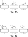
- FIG 4 illustrates the behavior of a drop of water deposited on the surface of two polyethylene filters, the first filter not having been treated ( figure 4A ) and the second filter having been treated by the fluorination process according to the invention described above in connection with figures 3A and 3B and leads to the difluor partial pressure of 3000 Pa ( figure 4B ).
- the contact angle ⁇ which is of the order of 90 ° when the drop of water is deposited, decreases over time, meaning that the external surface of the untreated polyethylene filter reveals properties of wettability and, as a result, water penetrates inside the porous structure of this filter under the influence of its own weight.
- the contact angle ⁇ remains at a value greater than 90 ° during the 5 min of observation, which means that the water does not penetrate into the porosity of the polyethylene filter treated by the fluorination process according to invention.
- the fluorinated filter therefore retains its hydrophobic properties over the same period.
Landscapes
- Chemical & Material Sciences (AREA)
- Chemical Kinetics & Catalysis (AREA)
- Health & Medical Sciences (AREA)
- General Chemical & Material Sciences (AREA)
- Medicinal Chemistry (AREA)
- Polymers & Plastics (AREA)
- Organic Chemistry (AREA)
- Clinical Laboratory Science (AREA)
- Devices For Use In Laboratory Experiments (AREA)
- Treatments Of Macromolecular Shaped Articles (AREA)
- Manufacture Of Porous Articles, And Recovery And Treatment Of Waste Products (AREA)
- Sampling And Sample Adjustment (AREA)
Claims (15)
- Verfahren zum Fluorieren eines Filters (26) für Pipettenspitzen Polyethylen und einem Polypropylen ausgewählt ist und es sich dabei insbesondere um ein Polyethylen handelt, dadurch gekennzeichnet, dass es die folgenden Schritte umfasst:(a) Bereitstellen des Filters (26) in einem Hohlraum,(b) Anlegen eines Vakuums an den Hohlraum und(c) Inkontaktbringen des Filters (26) mit einem Fluorierungsmittel, welches im gasförmigen Zustand in den Hohlraum eingeleitet wird,dadurch, dass das Fluorierungsmittel aus Difluor F2 besteht, dadurch, dass das Difluor F2 mit einem Partialdruck im Bereich von 100 Pa und 10 000 Pa, vorteilhafterweise von 500 Pa bis 8.000 Pa, und vorzugsweise von 750 Pa bis 6.000, in den geschlossenen Raum eingeleitet wird, unddadurch, dass der Schritt (c) bei einer Temperatur im Bereich von 0 °C bis 100 °C, vorteilhafterweise von 10 bis 60 °C,vorzugsweise von 15 °C bis 25 °C, durchgeführt wird.
- Fluorierungsverfahren nach Anspruch 1, wobei der Schritt (c) über eine Zeitdauer durchgeführt wird, die im Bereich von 1 min. bis 60 min., vorteilhafterweise von 2 min. bis 45 min., vorzugsweise von 5 min. bis 45 min., stärker bevorzugt von 10 min. bis 30 min. liegt.
- Fluorierungsverfahren nach Anspruch 1 oder 2, wobei während des Schrittes (c) eine Molanzahl an Difluor eingeleitet wird, die mindestens gleich der entsprechenden Molanzahl an Wasserstoffatomen des Polyolefins ist, wobei diese Molanzahl an Difluor vorteilhafterweise mindestens gleich dem 5-fachen und vorzugsweise gleich dem 10-fachen der entsprechenden Molanzahl an Wasserstoffatomen des Polyolefins ist.
- Fluorierungsverfahren nach einem beliebigen der Ansprüche 1 bis 3, wobei es weiterhin einen Schritt (d) des Entfernens der Nebenprodukte umfasst, welche sich während des Schrittes (c) gebildet haben.
- Fluorierungsverfahren nach Anspruch 4, wobei der Schritt (d) durchgeführt wird, indem die Nebenprodukte, welche sich während des Schrittes (c) gebildet haben, gasförmig abgeführt werden, wobei sie vorteilhafterweise unter Vakuum gasförmig abgeführt werden.
- Fluorierungsverfahren nach Anspruch 4 oder 5, wobei die Schritte (c) und (d) nacheinander durchgeführt werden.
- Fluorierungsverfahren nach Anspruch 4, wobei der Schritt (d) durchgeführt wird, indem die Nebenprodukte, welche sich während des Schrittes (c) gebildet haben, auf chemische Weise abgefangen werden.
- Fluorierungsverfahren nach einem beliebigen der Ansprüche 1 bis 7, wobei es weiterhin, nach dem Schritt (c), oder gegebenenfalls nach dem Schritt (d), einen Schritt (e1) umfasst, in welchem ein Vakuum an den Hohlraum angelegt wird, gefolgt von einem Schritt (e2), in welchem der Filter mit Diwasserstoff oder einer Mischung, welche Diwasserstoff umfasst, in Kontakt gebracht wird, wobei der Diwasserstoff oder die Mischung, welche Diwasserstoff umfasst, in gasförmigem Zustand in den Hohlraum eingeleitet wird, wobei die Molanzahl an Diwasserstoff, welche während des Schritts (e2) eingeleitet wird, vorteilweise höchstens gleich der Molanzahl an Difluor ist, welche während des Schrittes (c) eingeleitet wird.
- Fluorierungsverfahren nach Anspruch 8, wobei die Mischung Diwasserstoff und Stickstoff umfasst, wobei der Volumenprozentanteil an Diwasserstoff in dieser Mischung vorteilhafterweise mindestens 2 Vol.-% beträgt und vorteilhafterweise im Bereich von 5 Vol.-% bis 20 Vol.-% liegt.
- Fluorierungsverfahren nach Anspruch 8 oder 9, wobei der Schritt (e2) über eine Zeitdauer, die im Bereich von 10 min. bis 2 Std., vorteilhafterweise von 30 min. bis 60 min., liegt und/oder bei einer Temperatur durchgeführt wird, die im Bereich von 0 °C bis 200 °C, vorzugsweise von 20 °C min bis 80 °C liegt.
- Fluorierungsverfahren nach einem beliebigen der Ansprüche 1 bis 10, wobei der Druck in dem Hohlraum, während des Schrittes (b), und gegebenenfalls während des Schrittes (e1), höchstens 100 Pa, vorteilhafterweise höchstens 50 Pa und vorzugsweise höchstens 10 Pa beträgt.
- Fluorierungsverfahren nach einem beliebigen der Ansprüche 1 bis 11, wobei der Schritt (c) mittels Infrarotspektroskopie überwacht wird, insbesondere indem die Entwicklung des Verhältnisses ACH2/ACFx zwischen der Fläche der Infrarot-Schwingungsbanden, welche den -CH2-Gruppen entspricht, und der Somme der Flächen der Infrarot-Schwingungsbanden, welche den -CHF-Gruppen und den -CF2-Gruppen entspricht, mitverfolgt wird, wobei Schritt (c) insbesondere abgebrochen werden kann, sobald der Verhältnis ACH2/ACFx einen Wert von höchstens 15, vorteilhafterweise von höchstens 6 und vorzugsweise von höchstens 3 erreicht hat.
- Verfahren zur Herstellung einer Pipettenspitze (20), die einen fluorierten Filter (26) umfasst, wobei das Verfahren die folgenden Schritte umfasst:(i) Bereitstellen eines Filters (26), der von einer porösen feststofflichen Struktur aus Polyolefin, insbesondere aus Polyethylen gebildet wird,(ii) Anbringen des Filters (26) in der Pipettenspitze und(iii) Fluorieren des Filters (26), indem das Fluorierungsverfahren nach einem beliebigen der Ansprüche 1 bis 12 durchgeführt wird.
- Pipettenspitze (20), die einen Filter (26) umfasst, dadurch gekennzeichnet, dass der Filter (26) von einer porösen feststofflichen Struktur aus Polyolefin, insbesondere aus Polyethylen, gebildet wird, wobei die Fluoratome mindestens einen Teil der Wasserstoffatome des Polyolefins ersetzen, indem das Fluorierungsverfahren nach einem beliebigen der Ansprüche 1 bis 12 durchgeführt wird.
- Probennahmepipette (10), die eine Pipettenspitze (20) nach Anspruch 14 umfasst
Priority Applications (1)
| Application Number | Priority Date | Filing Date | Title |
|---|---|---|---|
| PL19710757T PL3727644T3 (pl) | 2018-02-20 | 2019-02-18 | Sposób fluorowania filtra końcówki pipety, końcówka pipety, sposób jej wytwarzania i powiązana pipeta |
Applications Claiming Priority (2)
| Application Number | Priority Date | Filing Date | Title |
|---|---|---|---|
| FR1851441A FR3077995B1 (fr) | 2018-02-20 | 2018-02-20 | Procede de fluoration d'un filtre d'embout de pipette, embout de pipette, son procede de fabrication et pipette associes |
| PCT/FR2019/050359 WO2019162602A1 (fr) | 2018-02-20 | 2019-02-18 | Procédé de fluoration d'un filtre d'embout de pipette, embout de pipette, son procédé de fabrication et pipette associés |
Publications (2)
| Publication Number | Publication Date |
|---|---|
| EP3727644A1 EP3727644A1 (de) | 2020-10-28 |
| EP3727644B1 true EP3727644B1 (de) | 2021-09-15 |
Family
ID=62222904
Family Applications (1)
| Application Number | Title | Priority Date | Filing Date |
|---|---|---|---|
| EP19710757.6A Active EP3727644B1 (de) | 2018-02-20 | 2019-02-18 | Verfahren zum fluorieren eines pipettenendfilters, pipettenendfilter, ihre herstellungsverfahren und entsprechende pipette |
Country Status (10)
| Country | Link |
|---|---|
| US (1) | US12005383B2 (de) |
| EP (1) | EP3727644B1 (de) |
| JP (1) | JP7398379B2 (de) |
| KR (1) | KR20200122321A (de) |
| CN (1) | CN111741804B (de) |
| CA (1) | CA3091301A1 (de) |
| ES (1) | ES2900662T3 (de) |
| FR (1) | FR3077995B1 (de) |
| PL (1) | PL3727644T3 (de) |
| WO (1) | WO2019162602A1 (de) |
Families Citing this family (1)
| Publication number | Priority date | Publication date | Assignee | Title |
|---|---|---|---|---|
| CN112827523A (zh) * | 2021-01-08 | 2021-05-25 | 上海金鑫生物科技有限公司 | 一种含活性炭的超高分子聚乙烯过滤器 |
Family Cites Families (33)
| Publication number | Priority date | Publication date | Assignee | Title |
|---|---|---|---|---|
| JPS58168630A (ja) * | 1982-03-29 | 1983-10-05 | バツテル・デイベロプメント・コ−ポレ−シヨン | 表面の調節フツ素化方法 |
| JPS61266442A (ja) | 1985-05-20 | 1986-11-26 | Asahi Chem Ind Co Ltd | フツ素化ポリオレフイン多孔体及びその製造方法 |
| JPH0730189B2 (ja) * | 1987-09-07 | 1995-04-05 | 三菱マテリアル株式会社 | 有機高分子材料の表面処理方法 |
| US5364595A (en) | 1993-07-02 | 1994-11-15 | Porex Technologies Corp. | Pipette device constructed to prevent contamination by aerosols or overpipetting |
| DE19514924A1 (de) * | 1995-04-22 | 1996-10-24 | Messer Griesheim Gmbh | Verfahren zur Konditionierung von organischen Substratoberflächen |
| JP4346754B2 (ja) * | 1999-10-26 | 2009-10-21 | 日東電工株式会社 | ピペット用フィルターの製作方法 |
| US6638610B1 (en) * | 2000-03-06 | 2003-10-28 | Porex Technologies Corp. | Water and oil repellent porous materials and processes for making the same |
| JP3759910B2 (ja) * | 2002-02-28 | 2006-03-29 | 日東電工株式会社 | チップ用フィルターおよびチップ |
| US7157117B2 (en) * | 2002-06-26 | 2007-01-02 | Sigma Laboratories Of Arizona, Llc | Functionalization of porous materials by vacuum deposition of polymers |
| JP4315366B2 (ja) * | 2003-02-03 | 2009-08-19 | 日東電工株式会社 | チップ用フィルター及びチップ |
| ATE519886T1 (de) * | 2003-04-25 | 2011-08-15 | Sigma Lab Arizona Inc | Durch vakuumablagerung funtionalisierte poröse materialien |
| JP2005279175A (ja) * | 2004-03-31 | 2005-10-13 | Terumo Corp | シリンジ |
| US7244291B2 (en) * | 2005-05-02 | 2007-07-17 | 3M Innovative Properties Company | Electret article having high fluorosaturation ratio |
| WO2007021814A2 (en) * | 2005-08-11 | 2007-02-22 | Eksigent Technologies, Llc | Plastic surfaces and apparatuses for reduced adsorption of solutes and methods of preparing the same |
| MY148625A (en) * | 2006-08-18 | 2013-05-15 | Porex Corp | Sintered polymeric materials and applications thereof |
| JP2009154134A (ja) * | 2007-12-27 | 2009-07-16 | Kao Corp | 油捕集用フィルタ |
| DE102010031240A1 (de) | 2010-07-12 | 2012-01-12 | Hamilton Bonaduz Ag | Pipettierspitze mit hydrophober Oberflächenausbildung |
| KR20120040356A (ko) * | 2010-10-19 | 2012-04-27 | 주식회사 노블바이오 | 불소 로우 리텐션 폴리머를 이용한 프리 바이오코팅 마이크로피펫 팁 |
| US8524170B2 (en) | 2011-02-22 | 2013-09-03 | Rainin Instrument, Llc | Pipette and sealing tip |
| US20120248034A1 (en) * | 2011-04-01 | 2012-10-04 | Lydall, Inc. | Methods of making and using liquid filter media |
| JP2013034941A (ja) * | 2011-08-08 | 2013-02-21 | Toyobo Co Ltd | 耐油性フィルター |
| WO2013083260A1 (en) * | 2011-12-06 | 2013-06-13 | Qiagen Gmbh | Recovery of a biomolecule comprising aqueous phase from a multiphasic mixture |
| JP2014008051A (ja) * | 2012-07-03 | 2014-01-20 | Hitachi Ltd | ろ過分離方法及びこれに使用するろ過分離装置 |
| CN105051515A (zh) * | 2013-02-26 | 2015-11-11 | 伊诺瓦普瑞普有限公司 | 具有一次性流体路径的液体到液体生物粒子浓缩器 |
| JP2014180591A (ja) * | 2013-03-18 | 2014-09-29 | Toyobo Co Ltd | 耐油性エレクトレットろ材 |
| CN104117396B (zh) * | 2013-04-26 | 2016-08-10 | 中国科学院化学研究所 | 具有超疏水性的移液枪枪头及其制备方法 |
| CN203379907U (zh) * | 2013-07-27 | 2014-01-08 | 烟台毓璜顶医院 | 一种移液器 |
| US10195542B2 (en) * | 2014-05-15 | 2019-02-05 | Hollingsworth & Vose Company | Surface modified filter media |
| CN204638219U (zh) * | 2015-05-11 | 2015-09-16 | 中华人民共和国宁德出入境检验检疫局 | 一种过滤移液器 |
| US20170137589A1 (en) * | 2015-11-16 | 2017-05-18 | Samsung Electronics Co., Ltd. | Methods of modifying surfaces of structures used in the manufacture of a semiconductor device via fluorination |
| CN107051230B (zh) * | 2017-06-21 | 2020-09-15 | 重庆大学 | 提升滤膜净化老化油性能的方法 |
| CN107224875A (zh) | 2017-08-03 | 2017-10-03 | 何浩明 | 一种反渗透膜的处理方法 |
| US10786787B2 (en) * | 2017-10-09 | 2020-09-29 | Samsung Electronics Co., Ltd. | Methods of fluorinating filters used in the manufacture of a semiconductor device |
-
2018
- 2018-02-20 FR FR1851441A patent/FR3077995B1/fr not_active Expired - Fee Related
-
2019
- 2019-02-18 EP EP19710757.6A patent/EP3727644B1/de active Active
- 2019-02-18 KR KR1020207023756A patent/KR20200122321A/ko not_active Withdrawn
- 2019-02-18 CN CN201980014167.4A patent/CN111741804B/zh active Active
- 2019-02-18 WO PCT/FR2019/050359 patent/WO2019162602A1/fr not_active Ceased
- 2019-02-18 CA CA3091301A patent/CA3091301A1/fr active Pending
- 2019-02-18 US US16/969,288 patent/US12005383B2/en active Active
- 2019-02-18 JP JP2020543819A patent/JP7398379B2/ja active Active
- 2019-02-18 ES ES19710757T patent/ES2900662T3/es active Active
- 2019-02-18 PL PL19710757T patent/PL3727644T3/pl unknown
Also Published As
| Publication number | Publication date |
|---|---|
| PL3727644T3 (pl) | 2022-03-07 |
| ES2900662T3 (es) | 2022-03-17 |
| JP2021514297A (ja) | 2021-06-10 |
| US20210008478A1 (en) | 2021-01-14 |
| CA3091301A1 (fr) | 2019-08-29 |
| FR3077995B1 (fr) | 2020-02-14 |
| KR20200122321A (ko) | 2020-10-27 |
| CN111741804A (zh) | 2020-10-02 |
| FR3077995A1 (fr) | 2019-08-23 |
| US12005383B2 (en) | 2024-06-11 |
| EP3727644A1 (de) | 2020-10-28 |
| JP7398379B2 (ja) | 2023-12-14 |
| WO2019162602A1 (fr) | 2019-08-29 |
| CN111741804B (zh) | 2022-12-09 |
Similar Documents
| Publication | Publication Date | Title |
|---|---|---|
| EP1899048A1 (de) | Hydrophobe oberflächenbeschichtung mit geringer benetzungshysterese, aufbringungsverfahren dafür, mikrokomponente und verwendung | |
| EP3474356A1 (de) | Mehrschichtenstruktur, die eine matte aus kohlenstoffnanoröhren als diffusionsschicht in einer protonenaustauschmembran-brennstoffzelle (pemfc) enthält | |
| CA3091301A1 (fr) | Procede de fluoration d'un filtre d'embout de pipette, embout de pipette, son procede de fabrication et pipette associes | |
| EP3837229A1 (de) | Verfahren zur herstellung eines konsolidierten verdichteten teils aus keramik oder kohlenstoff | |
| EP2131965A2 (de) | Dünnfilmbeschichtungsverfahren | |
| FR2647213A1 (fr) | Systeme echantillonneur automatique d'un liquide biologique a prelevement sterile | |
| EP0037306B1 (de) | Verfahren und Vorrichtung zur beschleunigten Verdichtung eines porösen Kohlenstoffsubstrats durch Zersetzung einer kohlenwasserstoffhaltigen Substanz bei Hochtemperatur und unter Hochdruck sowie Verfahren zur Herstellung dieser Substanz | |
| EP4251670A1 (de) | Polymer zur bildung einer gleitbeschichtung für einen ophthalmischen injektor | |
| EP3109339B1 (de) | Behandlungsverfahren eines werkstücks aus tantal oder einer tantallegierung | |
| EP2941316A1 (de) | Verfahren zur herstellung eines filters zur filterung von nanopartikeln, erhaltener filter und zugehöriges verfahren zur sammlung und quantitativen analyse von nanopartikeln | |
| EP3257585A1 (de) | Kappe und vorrichtung zur entnahme von mikroorganismen-kolonien, sowie entnahmeverfahren, bei dem diese eingesetzt werden | |
| FR2928733A1 (fr) | Dispositif de preparation d'echantillon | |
| FR2891052A1 (fr) | Procede de preparation d'un echantillon | |
| EP2744644B1 (de) | Verfahren, vorrichtung und verbundteil zur herstellung einer hybridlinse | |
| JPWO2009119265A1 (ja) | 塗布装置及びプラスチックレンズの製造方法 | |
| EP4486502A1 (de) | Verfahren zur festphasenextraktion mit einem porösen monolithen | |
| EP3697727A1 (de) | Verfahren zur herstellung einer mikrostrukturierten vorrichtung und zugehörige implementierungsvorrichtungen | |
| FR2563915A1 (fr) | Porte-echantillon pour la spectroscopie par absorption et emission atomiques sans flammes et son procede de fabrication | |
| FR2471599A1 (de) | ||
| WO2002068121A2 (fr) | Appareil pour le prelevement et le depot en microreseaux de solutions | |
| WO2006027690A2 (fr) | Dispositif et procede pour la separation et/ou la mesure des residus sur les surfaces des produits de la mecanique | |
| FR2918913A1 (fr) | Procede de protection du bois contre l'humidite efficace sur une longue duree | |
| EP1064065B2 (de) | Verfahren zur anreicherung optischer isomere in einem simulierten wanderbett | |
| FR2479173A1 (fr) | Procede et dispositif pour la densification acceleree d'un substrat carbone poreux par decomposition d'une substance hydrocarbonee a haute temperature et sous haute pression | |
| CA2772171C (fr) | Procede de lavage d'un materiau a base de polysaccharide ayant subi une oxydation |
Legal Events
| Date | Code | Title | Description |
|---|---|---|---|
| STAA | Information on the status of an ep patent application or granted ep patent |
Free format text: STATUS: UNKNOWN |
|
| STAA | Information on the status of an ep patent application or granted ep patent |
Free format text: STATUS: THE INTERNATIONAL PUBLICATION HAS BEEN MADE |
|
| PUAI | Public reference made under article 153(3) epc to a published international application that has entered the european phase |
Free format text: ORIGINAL CODE: 0009012 |
|
| STAA | Information on the status of an ep patent application or granted ep patent |
Free format text: STATUS: REQUEST FOR EXAMINATION WAS MADE |
|
| 17P | Request for examination filed |
Effective date: 20200721 |
|
| AK | Designated contracting states |
Kind code of ref document: A1 Designated state(s): AL AT BE BG CH CY CZ DE DK EE ES FI FR GB GR HR HU IE IS IT LI LT LU LV MC MK MT NL NO PL PT RO RS SE SI SK SM TR |
|
| AX | Request for extension of the european patent |
Extension state: BA ME |
|
| GRAP | Despatch of communication of intention to grant a patent |
Free format text: ORIGINAL CODE: EPIDOSNIGR1 |
|
| STAA | Information on the status of an ep patent application or granted ep patent |
Free format text: STATUS: GRANT OF PATENT IS INTENDED |
|
| DAV | Request for validation of the european patent (deleted) | ||
| DAX | Request for extension of the european patent (deleted) | ||
| INTG | Intention to grant announced |
Effective date: 20210511 |
|
| GRAS | Grant fee paid |
Free format text: ORIGINAL CODE: EPIDOSNIGR3 |
|
| GRAA | (expected) grant |
Free format text: ORIGINAL CODE: 0009210 |
|
| STAA | Information on the status of an ep patent application or granted ep patent |
Free format text: STATUS: THE PATENT HAS BEEN GRANTED |
|
| AK | Designated contracting states |
Kind code of ref document: B1 Designated state(s): AL AT BE BG CH CY CZ DE DK EE ES FI FR GB GR HR HU IE IS IT LI LT LU LV MC MK MT NL NO PL PT RO RS SE SI SK SM TR |
|
| REG | Reference to a national code |
Ref country code: CH Ref legal event code: EP |
|
| REG | Reference to a national code |
Ref country code: DE Ref legal event code: R096 Ref document number: 602019007740 Country of ref document: DE |
|
| REG | Reference to a national code |
Ref country code: IE Ref legal event code: FG4D Free format text: LANGUAGE OF EP DOCUMENT: FRENCH |
|
| REG | Reference to a national code |
Ref country code: AT Ref legal event code: REF Ref document number: 1430096 Country of ref document: AT Kind code of ref document: T Effective date: 20211015 |
|
| REG | Reference to a national code |
Ref country code: FI Ref legal event code: FGE |
|
| REG | Reference to a national code |
Ref country code: LT Ref legal event code: MG9D |
|
| REG | Reference to a national code |
Ref country code: NL Ref legal event code: MP Effective date: 20210915 |
|
| PG25 | Lapsed in a contracting state [announced via postgrant information from national office to epo] |
Ref country code: LT Free format text: LAPSE BECAUSE OF FAILURE TO SUBMIT A TRANSLATION OF THE DESCRIPTION OR TO PAY THE FEE WITHIN THE PRESCRIBED TIME-LIMIT Effective date: 20210915 Ref country code: BG Free format text: LAPSE BECAUSE OF FAILURE TO SUBMIT A TRANSLATION OF THE DESCRIPTION OR TO PAY THE FEE WITHIN THE PRESCRIBED TIME-LIMIT Effective date: 20211215 Ref country code: HR Free format text: LAPSE BECAUSE OF FAILURE TO SUBMIT A TRANSLATION OF THE DESCRIPTION OR TO PAY THE FEE WITHIN THE PRESCRIBED TIME-LIMIT Effective date: 20210915 Ref country code: NO Free format text: LAPSE BECAUSE OF FAILURE TO SUBMIT A TRANSLATION OF THE DESCRIPTION OR TO PAY THE FEE WITHIN THE PRESCRIBED TIME-LIMIT Effective date: 20211215 Ref country code: RS Free format text: LAPSE BECAUSE OF FAILURE TO SUBMIT A TRANSLATION OF THE DESCRIPTION OR TO PAY THE FEE WITHIN THE PRESCRIBED TIME-LIMIT Effective date: 20210915 Ref country code: SE Free format text: LAPSE BECAUSE OF FAILURE TO SUBMIT A TRANSLATION OF THE DESCRIPTION OR TO PAY THE FEE WITHIN THE PRESCRIBED TIME-LIMIT Effective date: 20210915 |
|
| REG | Reference to a national code |
Ref country code: AT Ref legal event code: MK05 Ref document number: 1430096 Country of ref document: AT Kind code of ref document: T Effective date: 20210915 |
|
| PG25 | Lapsed in a contracting state [announced via postgrant information from national office to epo] |
Ref country code: LV Free format text: LAPSE BECAUSE OF FAILURE TO SUBMIT A TRANSLATION OF THE DESCRIPTION OR TO PAY THE FEE WITHIN THE PRESCRIBED TIME-LIMIT Effective date: 20210915 Ref country code: GR Free format text: LAPSE BECAUSE OF FAILURE TO SUBMIT A TRANSLATION OF THE DESCRIPTION OR TO PAY THE FEE WITHIN THE PRESCRIBED TIME-LIMIT Effective date: 20211216 |
|
| REG | Reference to a national code |
Ref country code: ES Ref legal event code: FG2A Ref document number: 2900662 Country of ref document: ES Kind code of ref document: T3 Effective date: 20220317 |
|
| PG25 | Lapsed in a contracting state [announced via postgrant information from national office to epo] |
Ref country code: AT Free format text: LAPSE BECAUSE OF FAILURE TO SUBMIT A TRANSLATION OF THE DESCRIPTION OR TO PAY THE FEE WITHIN THE PRESCRIBED TIME-LIMIT Effective date: 20210915 |
|
| PG25 | Lapsed in a contracting state [announced via postgrant information from national office to epo] |
Ref country code: IS Free format text: LAPSE BECAUSE OF FAILURE TO SUBMIT A TRANSLATION OF THE DESCRIPTION OR TO PAY THE FEE WITHIN THE PRESCRIBED TIME-LIMIT Effective date: 20220115 Ref country code: SM Free format text: LAPSE BECAUSE OF FAILURE TO SUBMIT A TRANSLATION OF THE DESCRIPTION OR TO PAY THE FEE WITHIN THE PRESCRIBED TIME-LIMIT Effective date: 20210915 Ref country code: SK Free format text: LAPSE BECAUSE OF FAILURE TO SUBMIT A TRANSLATION OF THE DESCRIPTION OR TO PAY THE FEE WITHIN THE PRESCRIBED TIME-LIMIT Effective date: 20210915 Ref country code: RO Free format text: LAPSE BECAUSE OF FAILURE TO SUBMIT A TRANSLATION OF THE DESCRIPTION OR TO PAY THE FEE WITHIN THE PRESCRIBED TIME-LIMIT Effective date: 20210915 Ref country code: PT Free format text: LAPSE BECAUSE OF FAILURE TO SUBMIT A TRANSLATION OF THE DESCRIPTION OR TO PAY THE FEE WITHIN THE PRESCRIBED TIME-LIMIT Effective date: 20220117 Ref country code: NL Free format text: LAPSE BECAUSE OF FAILURE TO SUBMIT A TRANSLATION OF THE DESCRIPTION OR TO PAY THE FEE WITHIN THE PRESCRIBED TIME-LIMIT Effective date: 20210915 Ref country code: EE Free format text: LAPSE BECAUSE OF FAILURE TO SUBMIT A TRANSLATION OF THE DESCRIPTION OR TO PAY THE FEE WITHIN THE PRESCRIBED TIME-LIMIT Effective date: 20210915 Ref country code: CZ Free format text: LAPSE BECAUSE OF FAILURE TO SUBMIT A TRANSLATION OF THE DESCRIPTION OR TO PAY THE FEE WITHIN THE PRESCRIBED TIME-LIMIT Effective date: 20210915 Ref country code: AL Free format text: LAPSE BECAUSE OF FAILURE TO SUBMIT A TRANSLATION OF THE DESCRIPTION OR TO PAY THE FEE WITHIN THE PRESCRIBED TIME-LIMIT Effective date: 20210915 |
|
| PGFP | Annual fee paid to national office [announced via postgrant information from national office to epo] |
Ref country code: IT Payment date: 20220228 Year of fee payment: 4 Ref country code: ES Payment date: 20220303 Year of fee payment: 4 |
|
| REG | Reference to a national code |
Ref country code: DE Ref legal event code: R097 Ref document number: 602019007740 Country of ref document: DE |
|
| PLBE | No opposition filed within time limit |
Free format text: ORIGINAL CODE: 0009261 |
|
| STAA | Information on the status of an ep patent application or granted ep patent |
Free format text: STATUS: NO OPPOSITION FILED WITHIN TIME LIMIT |
|
| PG25 | Lapsed in a contracting state [announced via postgrant information from national office to epo] |
Ref country code: DK Free format text: LAPSE BECAUSE OF FAILURE TO SUBMIT A TRANSLATION OF THE DESCRIPTION OR TO PAY THE FEE WITHIN THE PRESCRIBED TIME-LIMIT Effective date: 20210915 |
|
| 26N | No opposition filed |
Effective date: 20220616 |
|
| PG25 | Lapsed in a contracting state [announced via postgrant information from national office to epo] |
Ref country code: MC Free format text: LAPSE BECAUSE OF FAILURE TO SUBMIT A TRANSLATION OF THE DESCRIPTION OR TO PAY THE FEE WITHIN THE PRESCRIBED TIME-LIMIT Effective date: 20210915 |
|
| REG | Reference to a national code |
Ref country code: BE Ref legal event code: MM Effective date: 20220228 |
|
| PG25 | Lapsed in a contracting state [announced via postgrant information from national office to epo] |
Ref country code: LU Free format text: LAPSE BECAUSE OF NON-PAYMENT OF DUE FEES Effective date: 20220218 |
|
| PG25 | Lapsed in a contracting state [announced via postgrant information from national office to epo] |
Ref country code: IE Free format text: LAPSE BECAUSE OF NON-PAYMENT OF DUE FEES Effective date: 20220218 |
|
| PG25 | Lapsed in a contracting state [announced via postgrant information from national office to epo] |
Ref country code: BE Free format text: LAPSE BECAUSE OF NON-PAYMENT OF DUE FEES Effective date: 20220228 |
|
| P01 | Opt-out of the competence of the unified patent court (upc) registered |
Effective date: 20230511 |
|
| PG25 | Lapsed in a contracting state [announced via postgrant information from national office to epo] |
Ref country code: IT Free format text: LAPSE BECAUSE OF NON-PAYMENT OF DUE FEES Effective date: 20230218 |
|
| REG | Reference to a national code |
Ref country code: ES Ref legal event code: FD2A Effective date: 20240326 |
|
| PG25 | Lapsed in a contracting state [announced via postgrant information from national office to epo] |
Ref country code: ES Free format text: LAPSE BECAUSE OF NON-PAYMENT OF DUE FEES Effective date: 20230219 |
|
| PG25 | Lapsed in a contracting state [announced via postgrant information from national office to epo] |
Ref country code: MK Free format text: LAPSE BECAUSE OF FAILURE TO SUBMIT A TRANSLATION OF THE DESCRIPTION OR TO PAY THE FEE WITHIN THE PRESCRIBED TIME-LIMIT Effective date: 20210915 Ref country code: ES Free format text: LAPSE BECAUSE OF NON-PAYMENT OF DUE FEES Effective date: 20230219 Ref country code: CY Free format text: LAPSE BECAUSE OF FAILURE TO SUBMIT A TRANSLATION OF THE DESCRIPTION OR TO PAY THE FEE WITHIN THE PRESCRIBED TIME-LIMIT Effective date: 20210915 |
|
| PG25 | Lapsed in a contracting state [announced via postgrant information from national office to epo] |
Ref country code: HU Free format text: LAPSE BECAUSE OF FAILURE TO SUBMIT A TRANSLATION OF THE DESCRIPTION OR TO PAY THE FEE WITHIN THE PRESCRIBED TIME-LIMIT; INVALID AB INITIO Effective date: 20190218 |
|
| PG25 | Lapsed in a contracting state [announced via postgrant information from national office to epo] |
Ref country code: MT Free format text: LAPSE BECAUSE OF FAILURE TO SUBMIT A TRANSLATION OF THE DESCRIPTION OR TO PAY THE FEE WITHIN THE PRESCRIBED TIME-LIMIT Effective date: 20210915 |
|
| PG25 | Lapsed in a contracting state [announced via postgrant information from national office to epo] |
Ref country code: TR Free format text: LAPSE BECAUSE OF FAILURE TO SUBMIT A TRANSLATION OF THE DESCRIPTION OR TO PAY THE FEE WITHIN THE PRESCRIBED TIME-LIMIT Effective date: 20210915 |
|
| PG25 | Lapsed in a contracting state [announced via postgrant information from national office to epo] |
Ref country code: SI Free format text: LAPSE BECAUSE OF FAILURE TO SUBMIT A TRANSLATION OF THE DESCRIPTION OR TO PAY THE FEE WITHIN THE PRESCRIBED TIME-LIMIT Effective date: 20210915 |
|
| REG | Reference to a national code |
Ref country code: CH Ref legal event code: U11 Free format text: ST27 STATUS EVENT CODE: U-0-0-U10-U11 (AS PROVIDED BY THE NATIONAL OFFICE) Effective date: 20260301 |
|
| PGFP | Annual fee paid to national office [announced via postgrant information from national office to epo] |
Ref country code: GB Payment date: 20260220 Year of fee payment: 8 |
|
| PGFP | Annual fee paid to national office [announced via postgrant information from national office to epo] |
Ref country code: DE Payment date: 20260218 Year of fee payment: 8 |
|
| PGFP | Annual fee paid to national office [announced via postgrant information from national office to epo] |
Ref country code: FI Payment date: 20260226 Year of fee payment: 8 |
|
| PGFP | Annual fee paid to national office [announced via postgrant information from national office to epo] |
Ref country code: FR Payment date: 20260218 Year of fee payment: 8 |
|
| PGFP | Annual fee paid to national office [announced via postgrant information from national office to epo] |
Ref country code: CH Payment date: 20260301 Year of fee payment: 8 |
|
| PGFP | Annual fee paid to national office [announced via postgrant information from national office to epo] |
Ref country code: PL Payment date: 20260209 Year of fee payment: 8 |