EP3725430A1 - Molten material processing device - Google Patents
Molten material processing device Download PDFInfo
- Publication number
- EP3725430A1 EP3725430A1 EP18888361.5A EP18888361A EP3725430A1 EP 3725430 A1 EP3725430 A1 EP 3725430A1 EP 18888361 A EP18888361 A EP 18888361A EP 3725430 A1 EP3725430 A1 EP 3725430A1
- Authority
- EP
- European Patent Office
- Prior art keywords
- molten material
- dam
- inlet part
- processing device
- container
- Prior art date
- Legal status (The legal status is an assumption and is not a legal conclusion. Google has not performed a legal analysis and makes no representation as to the accuracy of the status listed.)
- Withdrawn
Links
- 239000012768 molten material Substances 0.000 title claims abstract description 261
- 238000012545 processing Methods 0.000 title claims abstract description 51
- 230000004308 accommodation Effects 0.000 claims abstract description 6
- 239000000155 melt Substances 0.000 claims description 24
- 230000001965 increasing effect Effects 0.000 abstract description 3
- 229910000831 Steel Inorganic materials 0.000 description 40
- 239000010959 steel Substances 0.000 description 40
- 230000000052 comparative effect Effects 0.000 description 34
- 238000011156 evaluation Methods 0.000 description 15
- 238000000034 method Methods 0.000 description 14
- 238000009749 continuous casting Methods 0.000 description 12
- 238000009826 distribution Methods 0.000 description 7
- 238000001816 cooling Methods 0.000 description 6
- 238000013461 design Methods 0.000 description 6
- 238000004519 manufacturing process Methods 0.000 description 6
- 230000000694 effects Effects 0.000 description 5
- 238000004458 analytical method Methods 0.000 description 4
- 239000002893 slag Substances 0.000 description 4
- 238000002474 experimental method Methods 0.000 description 3
- 230000001939 inductive effect Effects 0.000 description 3
- 230000000717 retained effect Effects 0.000 description 3
- 238000000926 separation method Methods 0.000 description 3
- XKRFYHLGVUSROY-UHFFFAOYSA-N Argon Chemical compound [Ar] XKRFYHLGVUSROY-UHFFFAOYSA-N 0.000 description 2
- 238000005266 casting Methods 0.000 description 2
- 238000007654 immersion Methods 0.000 description 2
- 230000002411 adverse Effects 0.000 description 1
- 238000013019 agitation Methods 0.000 description 1
- 229910052786 argon Inorganic materials 0.000 description 1
- 238000005520 cutting process Methods 0.000 description 1
- 230000007423 decrease Effects 0.000 description 1
- 238000005206 flow analysis Methods 0.000 description 1
- 239000012530 fluid Substances 0.000 description 1
- 239000007789 gas Substances 0.000 description 1
- 230000006698 induction Effects 0.000 description 1
- 238000009434 installation Methods 0.000 description 1
- 239000011229 interlayer Substances 0.000 description 1
- 239000000463 material Substances 0.000 description 1
- 238000012805 post-processing Methods 0.000 description 1
- 239000011819 refractory material Substances 0.000 description 1
- 238000005096 rolling process Methods 0.000 description 1
- 238000010079 rubber tapping Methods 0.000 description 1
Images


Classifications
-
- B—PERFORMING OPERATIONS; TRANSPORTING
- B22—CASTING; POWDER METALLURGY
- B22D—CASTING OF METALS; CASTING OF OTHER SUBSTANCES BY THE SAME PROCESSES OR DEVICES
- B22D41/00—Casting melt-holding vessels, e.g. ladles, tundishes, cups or the like
- B22D41/003—Casting melt-holding vessels, e.g. ladles, tundishes, cups or the like with impact pads
-
- B—PERFORMING OPERATIONS; TRANSPORTING
- B22—CASTING; POWDER METALLURGY
- B22D—CASTING OF METALS; CASTING OF OTHER SUBSTANCES BY THE SAME PROCESSES OR DEVICES
- B22D11/00—Continuous casting of metals, i.e. casting in indefinite lengths
- B22D11/10—Supplying or treating molten metal
- B22D11/103—Distributing the molten metal, e.g. using runners, floats, distributors
-
- B—PERFORMING OPERATIONS; TRANSPORTING
- B22—CASTING; POWDER METALLURGY
- B22D—CASTING OF METALS; CASTING OF OTHER SUBSTANCES BY THE SAME PROCESSES OR DEVICES
- B22D11/00—Continuous casting of metals, i.e. casting in indefinite lengths
- B22D11/10—Supplying or treating molten metal
- B22D11/11—Treating the molten metal
- B22D11/116—Refining the metal
- B22D11/118—Refining the metal by circulating the metal under, over or around weirs
-
- B—PERFORMING OPERATIONS; TRANSPORTING
- B22—CASTING; POWDER METALLURGY
- B22D—CASTING OF METALS; CASTING OF OTHER SUBSTANCES BY THE SAME PROCESSES OR DEVICES
- B22D41/00—Casting melt-holding vessels, e.g. ladles, tundishes, cups or the like
Definitions
- the present invention relates to a molten material processing device and, more particularly, to a molten material processing device in which a dead volume is reduced to improve inclusion removal capacity.
- Continuous casting apparatuses generally include a ladle for conveying molten steel, a tundish for receiving the molten steel from the ladle and temporarily storing the molten steel, a mold for primarily solidifying the molten steel into a slab while continuously receiving the molten steel from the tundish, and a cooling zone for secondarily cooling the slab continuously drawn from the mold and performing a series of forming operations.
- Patent Document 1 proposes a method for constructing a plurality of refractory dams such as a dam, an auxiliary dam, and an induction dam within a tundish and then injecting an argon gas into molten steel through the auxiliary dam, thereby actively inducing an upward flow, rather than using a method for controlling a flow of molten steel utilizing a dam and a weir.
- Patent Document 2 proposes a method for mounting an impact pad and a separation wall on a lower side of a shroud nozzle and allowing the molten steel to collide with the impact pad and to pass through a space between the separation wall and the impact pad, thereby actively inducing an upward flow of the molten steel.
- the dead volume of the molten steel within the tundish increases, the degree to which the molten steel is retained within the dead volume becomes inappropriate, and the residence time of the molten steel may become excessively long. That is, when the dead volume of the molten steel within the tundish increases, the appropriate residence time of the molten steel within the tundish is not ensured. Also, when inclusions enter the dead volume, the inclusions are retained in a center of the dead volume due to a low flow rate of the molten steel, which prevents the inclusions from being floated and separated from the molten steel. The inclusions flow in a mold and cause inclusion-related quality failure in the slab.
- the occurrence of the dead volume has to be minimized while actively inducing the upward flow of the molten steel within the tundish.
- the present invention provides a molten material processing device capable of ensuring a sufficient and appropriate residence time of a molten material accommodated in a container.
- the present invention provides a molten material processing device capable of reducing a dead volume of a molten material to improve inclusion removal capacity.
- the present invention provides a molten material processing device capable of widely distributing an upward flow that reaches a top surface of a molten material.
- a molten material processing device includes: a container which includes a molten material accommodation space formed therein, a molten material inlet part disposed at one side thereof, and a molten material outlet formed at the other side thereof; and a dam which is positioned between the molten material inlet part and the molten material outlet so that one surface thereof directly faces the molten material inlet part, and which is mounted on a bottom of the container and connected to two longitudinal direction side walls, wherein the dam is mounted on a drop area of a molten material formed below the molten material inlet part and has a top surface positioned in an upper portion of the molten material.
- the dam may be mounted on an edge portion of the drop area.
- the other surface of the dam directly may face a width direction side wall on the molten material outlet side.
- a size of the drop area may be proportional to an inner diameter of the molten material inlet part, and a distance between the one surface of the dam and the molten material inlet part may be proportional to the size of the drop area.
- a distance between the one surface of the dam and the molten material inlet part may be in a range of 2.5 to 5 times an inner diameter of the molten material inlet part.
- a height of the top surface of the dam may be in a range of 0.5 to 0.75 times a melt height of the molten material.
- the molten material processing device may further include a through-hole formed in the dam.
- the through-hole may be formed in a lower portion of the dam, defined in a direction from the one side toward the other side, and have an inner wall directly connected to the bottom.
- the dam is mounted on the bottom of the container so as to be positioned on the edge of the pouring zone of the molten material, and the height of the top surface of the dam may be optimized, thereby optimizing the flow field of the molten material.
- the sufficient and appropriate residence time of the molten material accommodated in the container may be ensured, and the dead volume of the molten material may be reduced to improve the inclusion removal capacity.
- the strong flow of the molten steel within the pouring zone is directed to the top surface of the molten material to form the upward flow, thereby widely distributing the upward flow that reaches the top surface of the molten material and further improving the inclusion removal capacity.
- the inclusion in the molten material may be smoothly floated and separated to improve the cleanness of molten material, thereby improving the quality of the product made of the molten material.
- the additional structure for reducing the flow rate of the molten material within the container may not be necessarily mounted, and the size and the number of the refractory structures mounted within the container may be minimized and optimized to simplify the structure. Therefore, the manufacturing costs may be reduced.
- a molten material processing device provides a technical feature of reducing a dead volume of a molten material while increasing an area that an upward flow reaches in a top surface of the molten material, thereby improving inclusion removal capacity.
- the molten material processing device is used in a continuous casting process of a steel mill, and may also be used in diverse casting processes using various molten materials. The embodiment of the present invention will be described with reference to the continuous casting process.
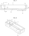
- FIGS. 7 and 8 are schematic views illustrating a molten material processing device according to the embodiment of the present invention.
- FIG. 7 is a cross-sectional view of the molten material processing device
- FIG. 8 is a perspective view of the molten material processing device.
- one direction is referred to as a direction in which one width direction side wall 1a is spaced apart from the other width direction side wall 1b
- a vertical direction is referred to as a direction in which a molten material inlet part 2 extends.
- the other direction is referred to as a direction perpendicular to both the one direction and a height direction.
- the other direction is a direction in which a dam 3 of FIG. 8 extends.
- the one direction may be referred to as a longitudinal direction
- the other direction may be referred to as a width direction
- the vertical direction may be referred to as the height direction.
- the molten material processing device includes a container 1 including a molten material accommodation space formed therein, a molten material inlet part 2 disposed at one side thereof, and a molten material outlet 1c formed at the other side thereof.
- the molten material processing device includes a dam 3 which is positioned between the molten material inlet part 2 and the molten material outlet 1c so that one surface thereof directly faces the molten material inlet part 2, and which is mounted on a bottom of the container 1 and connected to two longitudinal direction side walls 1d.
- the dam 3 is mounted on a drop area of a molten material formed below the molten material inlet part 2 and has a top surface positioned in an upper portion of the molten material.
- the molten material may include molten steel.
- the molten material is stored in a conveyance container, for example, a ladle (not shown) and conveyed to the molten material processing device.
- the molten material may be positioned above the container 1 and connected to the molten material inlet part 2.
- the molten material may be injected into the container 1 via the molten material inlet part 2.
- the molten material may include various materials in addition to the molten steel.
- a lower portion of the molten material is a section ranging from the bottom of the container 1 to a height that is less than 0.5 times the height of a melt height of the molten material.
- an upper portion of the molten material is a section ranging from a height, which is 0.5 times the melt height of the molten material, to the melt height of the molten material. For example, when the height of the bottom of the container 1 is zero, and the melt height of the molten material is 1, the height from 0 to a height that is less than 0.5 corresponds to the lower portion of the molten material, and the height from 0.5 to 1 corresponds to the upper portion of the molten material.
- the melt height of the molten material is referred to as the height of the molten material that has the constant height within the container 1 in a steady state during the continuous casting process.
- the melt height of the molten material may be referred to as a molten steel level or a melt level.
- the steady state means that a flow of the molten material within the container 1 is in a steady state.
- the molten material inlet part 2 is a refractory nozzle through which the molten material is able to pass, and may be a shroud nozzle.
- the molten material inlet part 2 is mounted on a manipulator (not shown), and as the manipulator rises, an opening of an upper end thereof may be coupled to a collector nozzle (not shown) of a conveyance container.
- the molten material inlet part 2 may be disposed at one side of the container 1 and spaced apart from the bottom of the container 1. Also, an opening of an lower end thereof may be positioned within the container 1, and at least a portion thereof may be immersed in the molten material.
- a molten material-dropping area (hereinafter, referred to as a drop area) is defined below the molten material inlet part 2.
- the drop area is an area through which the molten material, which has passes through the molten material inlet part 2 and then has been injected into the container 1, passes first.
- the molten material having relatively high energy after falling from the molten material inlet part 2 and colliding with the bottom of the container 1, may flow along the bottom at a predetermined flow rate. Subsequently, as moving away from the drop area, the flow rate of the molten material gradually decreases, and the molten material having relatively low energy may flow at a normal flow rate.
- the drop area is formed on the bottom of the container 1, and a center c thereof is vertically aligned with a vertical central axis (not shown) passing through a center of the molten material inlet part 2.
- the size of the drop area for example, the width in the one direction is proportional to the inner diameter of the molten material inlet part 2. As the inner diameter of the molten material inlet part 2 increases, the size of the drop area also increases in proportion to the inner diameter of the molten material inlet part 2.
- the inner diameter of the molten material inlet part 2 may be an inner diameter with respect to the opening of the lower end of the molten material inlet part 2, and the one direction may be a direction from the molten material inlet part 2 toward the molten material outlet 1c, as a direction in which the container 1 extends.
- a distance between an edge end of the drop area in the one direction and the center c may be 2.5 to 5 times an inner diameter d of the molten material inlet part 2.
- the molten material may actively flow within a predetermined range of flow rates.
- the molten material in the drop area has a meaningful flow rate.
- the molten material has the meaningful flow rate means that the molten material has a flow rate enough to form an upward flow instead of descending after colliding with the dam 3 and flooding.
- the flow of the molten material in the drop area may affect the entire flow of the molten material within the container 1, and thus the drop area may be significantly meaningful area.
- the drop area may be referred to as a pouring zone.
- the container 1 includes the accommodation space formed therein, the molten material inlet part 2 disposed at the one side thereof, and the molten material outlet 1c formed at the other side thereof.
- the container 1 may include, for example, a tundish.
- the tundish may be a rectangular tundish that lengthily extending in the one direction.
- the container 1 may include a rectangular bottom extending in the one direction and the other direction perpendicular to the one direction, two longitudinal direction side walls 1d which respectively extend along two long sides of edges of the bottom in the one direction and protrude vertically, and one width direction side wall 1a and the other width direction side wall 1b which respectively extend along two short sides of the edges of the bottom in the other direction and protrude vertically.
- the molten material inlet part 2 may be disposed relatively close to the one width direction side wall 1a, and the molten material outlet 1c may be disposed relatively close to the other side wall 1b.
- the bottom of the container 1 may have a stepped portion in which the height at the other side is lower than the height at the one side.
- a molten material accommodation space may be formed by the bottom, the two longitudinal direction side walls Id, the one width direction side wall 1a, and the other width direction side wall 1b.
- the two longitudinal direction side walls 1d face each other in the other direction, and the one width direction side wall 1a and the other width direction side wall 1b face each other in the one direction.
- the molten material inlet part 2 is disposed at one side of the bottom, and the molten material inlet part 2 may be vertically spaced apart from the one side of the bottom and disposed in the upper portion of the container 1. Also, the molten material outlet 1c may be formed by vertically passing through the other side of the bottom.
- An outlet nozzle (not shown), for example, an immersion nozzle is installed to pass through the molten material outlet 1c from below the container 1, and a mold (not shown) surrounding a lower portion of the immersion nozzle is disposed.
- An opening degree of the molten material outlet 1c is adjusted by a slide gate (not shown) and may discharge the molten material into the mold. In the mold, the molten material may be solidified into a slab.
- a cooling zone (not shown) may be provided below the mold.
- a series of forming operations is performed by cooling and pushing down the slab continuously drawn from the mold.
- the slab that has passes through the cooling zone is cut by a cutting part, and then may be conveyed to rolling equipment or various post-processing equipment according to purposes.
- the container 1 has functions of adjusting and distributing a supply of the molten material to a mold (not shown), reducing pressure due to weight of the molten material, for example, ferrostatic pressure, and removing an inclusion through a flow control of the molten material to improve the cleanness.
- a dam 4 is mounted on the bottom of the container 1 so as to remove the inclusion.
- the dam 4 has a function of controlling the flow of the molten material to increase a residence time of the molten material, thereby floating the slag and the inclusion, contained in the molten material, to the top surface of the molten material, for example, to a melt surface. As the slag and inclusion floating to the top surface are separated from the molten material, the mixing of the inclusion and the slag into the mold may be minimized.
- the dam 3 is positioned between the molten material inlet part 2 and the molten material outlet 1c so that one surface thereof directly faces the molten material inlet part 2, and is mounted on the bottom of the container 1, extends in the other direction, and is connected to the facing surfaces of the two longitudinal direction side walls 1d.
- the dam 3 may raise the flow of the molten material, which is supplied from the molten material inlet part 2 to the container 1 and flows along the bottom, toward the upper portion of the container 1.
- the one surface of the dam 3 is a surface which faces the molten material inlet part 2 and one width direction side wall 1a among two side surfaces of the dam 3 extending in the width direction and the vertical direction.
- the other surface of the dam 3 is a surface which faces the molten material outlet 1c and the other width direction side wall 1b among the two side surfaces of the dam 3 described above.
- the one surface of the dam 3 may be referred to as a front surface
- the other surface of the dam 3 may be referred to as a rear surface.
- the feature, in which the dam 3 is positioned between the molten material inlet part 2 and the molten material outlet 1c so that one surface thereof directly faces the molten material inlet part 2, means that there are no separate structures between the dam 3 and the molten material inlet part 1.
- the separate structures may include various wall bodies such as weirs and auxiliary dams, containers such as impact pads, and other various structures having diverse shapes. That is, since a separate structure is not mounted between the dam 3 and the molten material inlet part 2, the one surface of the dam 3 may directly face the molten material inlet part 2.
- the dam 3 is mounted to directly face the molten material inlet part 2 and, the flow of the molten material supplied to the drop area may be controlled by being affected directly by the dam 3 without interference. That is, after dropping to the bottom, the molten material collides with the dam 3 first, and thus the upward flow may be formed.
- the dam 3 may be mounted on the drop area so as to effectively induce the upward flow of the molten material.
- the dam 3 in order to avoid direct collision with the molten material that is being dropping, the dam 3 is mounted on an edge portion of the drop area in the other direction, facing the molten material within the drop area.
- the dam 3 may first come into contact with the molten material that flows along the bottom of the container 1 in a direction from the one side toward the other side of the container 1. That is, at the edge portion of the drop area, the dam 3 may be directly exposed to the molten material within the drop area and may come into direct contact with the same.
- coming into direct contact with means that, for example, the molten material first comes into contact with the dam 3 before the flow of the molten material is controlled due to the collision with a separate structure.
- the dam 3 since only the dam 3 is provided within the drop area, the molten material within the drop area may come into contact only with the dam 3 except for the bottom and the side walls of the container 1.
- the other surface of the dam 3 may directly face the width direction side wall 1b at the molten material outlet 1c. That is, there are also no separate structures between the dam 3 and the molten material outlet 1c. As described above, only one dam 3 is mounted within the container 1, and the flow of the molten material may be controlled by the one dam 3.
- the distance between the one surface of the dam 3 and the molten material inlet part 2 may be proportional to the size of the drop area. As the size of the drop area increases, a distance L between the one surface of the dam 3 and the molten material inlet part 2 may increase. Here, the distance between the one surface of the dam 3 and the molten material inlet part 2 may be in a range of 2.5 to 5 times an inner diameter d of the molten material inlet part. Accordingly, at least one surface of the dam 3 may be positioned on the edge portion of the drop area. The top surface of the dam 3 may be positioned in the upper portion of the molten material.
- the height H of the top surface of the dam 3 may be in a range of 0.5 to 0.75 times the melt height of the molten material.
- the height of the top surface of the dam 3 is less than 0.5 times the melt height of the molten material, a smooth upward flow may not be formed, and it is difficult for the molten material to widely rise to the melt surface.
- the dam 3 may prevent the molten material from being widely spread to the melt surface.
- the height of the top surface of the dam 3 exceeds 0.75 times the melt height of the molten material, the molten material rises over the current melt level and overflows. Thus, the molten material may flow to the outside of the container 1.
- the molten material processing device described above is referred to as a molten material processing device according to a first embodiment.
- a molten material processing device according to a second embodiment of the present invention will be described.
- the molten material processing device according to the second embodiment of the present invention includes the components described in the molten material processing device according to the first embodiment, and further include a through-hole (not shown) to be formed in the dam 3.
- the through-hole may be formed in a lower portion of the dam 3, defined in a direction from the one side toward the other side of the container 1, and have an inner wall directly connected to the bottom of the container 1.
- the dam 3 is mounted within the container 1. Also, the mounting position thereof is set to be the edge portion of the drop area, and the top surface thereof is positioned in the upper portion of the molten material.
- the inner profile of the container 1 is designed as described above, and the flow of the molten material is controlled. Thus, the upward flow may be generated from the drop area, and the flow of the molten material may be induced so that the dead volume within the container 1 is less than 10%. Through this, the inclusion removal efficiency may be improved by 50% or more when compared to the related art. In addition, manufacturing costs for refractories may be reduced due to the non-use of the weir, and manufacturing costs for molten steel may be reduced.
- the dam structure of the molten material processing device according to the embodiments of the present invention described above may be referred to as, for example, a tundish dam structure having the dead volume of 10% or less for manufacturing ultra clean steel.
- the molten material processing device may widely distribute the upward flow that reaches the top surface of the molten material while reducing the dead volume of the molten material to improve the inclusion removal capacity.
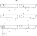
- FIG. 1 is a view illustrating modeling structures for flow evaluation of molten material processing devices according to an embodiment of the present invention and comparative examples.
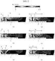
- FIG. 2 is a view showing flow evaluation results of the molten material processing devices according to the embodiment of the present invention and the comparative examples.
- FIG. 3 is a view showing quantitative numerical values of flow characteristics of the molten material derived from the flow evaluation results according to the embodiment of the present invention and the comparative examples.
- the molten material processing device is a device for ultimately reducing an inclusion in a molten material according to shapes and design parameters of a dam in a continuous casting process.
- various types of structures are constructed within a container 1, and then the flow characteristics are analyzed.
- the inner shape within the container 1, for example, the shape and design parameters of a dam 3 are designed with an optimal profile.
- a height of a top surface of a dam 3 is 2/3 of a melt height of a molten material, for example, 600 mm.
- a modeling structure of a molten material processing device according to a comparative example 2 in which an impact pad 4 is mounted right below a molten material inlet part 2
- a modeling structure of a molten material processing device according to a comparative example 3 in which an auxiliary dam 5 having a height of a top surface as low as 40 mm is mounted in a drop area, and a dam including a through-hole is mounted behind the auxiliary dam.
- the dam including the through-hole is not mounted to directly face a molten material inlet part 2.
- a top surface of the dam including the through-hole is 1/2 of a melt height of a molten material, for example, 450 mm, and the mounting position is outside a drop area.
- the dam including the through-hole is designated by a reference numeral 3' to be distinguished from the dam 3 of the embodiment 1.
- a modeling structure of a molten material processing device according to a comparative example 4 of the present invention Only an auxiliary dam 5 is mounted within a drop area.
- a modeling structure of a molten material processing device according to a comparative example 5 of the present invention An auxiliary dam 5 is mounted away from a drop area and closer to a molten material outlet 1c than a molten material inlet part 2, for example, at a position where the distance from a center of the drop area is 1500 mm.
- inner diameters of molten material inlets in the modeling structures of FIG. 1 are set to 160 mm.
- the structure of the dam 3 of the molten material processing device has an optimized profile to increase a plug volume within the molten material and reduce a dead volume.
- the inclusion removal capacity in the molten material may be evaluated through a residence time distribution graph.
- FIG. 3 shows quantitative numerical values with which flow characteristics of the molten material may be analyzed through the residence time distribution graph for modeling shapes of the embodiment and the comparative examples shown in FIG. 1 .
- a continuous casting apparatus for a numerical model experiment is configured, the numerical model experiment for a continuous casting process is performed, a certain amount of an experimental solution (a dye) is injected for 2 to 3 seconds, and the concentration of the solution is detected at the outlet over a time.
- the results are plotted on a dimensionless time axis, and thus the residence time distribution curve is made.
- the residence time distribution curve may be a standard concentration graph over a dimensionless time measured at an outlet when a dye is input to an inlet of the flow.
- the curve may be derived using numerical analysis not the numerical model experiment. Using the residence time distribution curve, a mixing degree of the molten steel and an inclusion floating/separating effect, for example, according to changes in capacity and inner shape of the tundish may be determined.
- a Min. Time is a time when the concentration of experimental solution is detected first.
- a peak time is a time when the concentration of experimental solution is highest.
- a mean time is a value obtained by dividing the inner volume of the container 1 by the input flow rate of the molten material int the molten material inlet part 2. The input flow rates of the molten material are equal to each other in the embodiment and comparative examples, but the inner volumes of the containers 1 are different from each other according to the inner profiles of the containers 1.
- An active mean residence time is a value obtained by dividing an area of the curve by an average residence time when a dimensionless value of a measured average time is 2 or higher.
- An active region fraction or an active volume fraction is a fraction of regions in which the molten steel is mixed, and includes a plug volume fraction and a mixed volume fraction.
- a dead region fraction or a dead volume fraction is a fraction of regions in which the molten material very slowly flows for a time twice as long as the average residence time of the molten material within the container.
- the molten steel volume within the tundish is divided into an active volume and a dead volume.
- the active volume is a region in which the molten steel is mixed, but the dead volume is a region in which the mixing does not occur.
- the active volume is divided into a plug volume and a mixed volume.
- the plug volume the molten steel flows at a constant flow rate in a pipe flow, and mixing in the flow direction, that is, in the horizontal direction occurs over the entire regions without interlayer mixing.
- the mixed volume is a region in which the mixing is highest, and mechanical agitation occurs.
- the dead volume is referred to as a stagnation region, and is a region where a fluid moves very slowly within the container and stays for a time twice as long as the average residence time.
- Vp is referred to as the plug volume fraction
- Vd is referred to as the dead volume fraction
- Vm the mixed volume fraction.
- the peak time is related to the plug volume, and it may be confirmed that the highest value is shown in the embodiment. That is, embodiment 1 shows the best result.
- Referring to a ratio of the dead volume it may be confirmed that embodiment 1 and comparative example 2 show a value of less than 10%. It may be confirmed that other comparative examples have greater than 10%.
- the embodiment 1 with comparative example 1 it may be confirmed that there is an effect of reduction in dead volume of 4.7% to 5.8%.
- the inclusion removal capacity there is an effect of the inclusion removal of 41% to 50%.
- Embodiment 1 and comparative example 2 show the best results.
- FIG. 4 is a view illustrating modeling structures for flow evaluation of molten material processing devices according to embodiments of the present invention and comparative examples.
- FIG. 5 is a view showing quantitative numerical values of flow characteristics of the molten material derived from the flow evaluation results according to the embodiments of the present invention and the comparative examples.
- FIG. 6 is a view showing flow evaluation results according to the embodiments of the present invention.
- PI is a mounting position of the dam 3 according to embodiment 1
- P2 is a position spaced L from PI in a rearward direction
- P3 is a position spaced 2L from PI in the rearward direction.
- L is set to 500 mm, and the flow evaluation was performed.
- a position in FIG. 5 is a mounting position of the dam 3.
- P1+P2 in comparative example 10 and comparative example 11 means that dams 3 are mounted at both PI position and P2 position. Similarly, others represent mounting positions.
- a hole existence means that whether there is a through-hole or not.
- embodiment 1 and embodiment 2 have very small values. That is, when the dam is constructed as in embodiment 1, and the through-hole is provided, it may be confirmed that the inclusion removal capacity is further improved. On the other hand, referring to comparative examples 6 to 17, it may be confirmed that, when a dam is mounted farther, or several dams are mounted in places in addition to the drop area, the inclusion removal capacity is adversely affected.
- the distance between the center c of the drop area and the one width direction side wall 1a has to be greater than the distance between the center c of the drop area and the one surface of the dam 3 and smaller than the distance between the center c of the drop area and the other surface of the dam 3.
- the width of the dam 3 in the one direction for example, the thickness has to be 50 mm to 200 mm.
- the height of the top surface of the dam 3 has to be lager than 1/2 and smaller than 3/4 of the melt height of the molten material.
- the distance between the one surface of the dam 3 and the molten material inlet part 2 may be in a range of 2.5 to 5 times the inner diameter of the molten material inlet part 2, and the height of the top surface of the dam 3 is in a range of 0.5 to 0.7 times the melt height of the molten material. Therefore, before turbulent flow energy of the molten material that flows in the pouring zone is dissipated, the turbulent flow of the molten material within the pouring zone is controlled using the dam 3. Accordingly, the molten material may overflow the upper portion of the dam 3, and the sufficient upward flow may be stably formed. Thus, the size of the dead volume of the molten material may be reduced to a half level when compared to the related art, and in the continuous casting process in which the molten material processing device is used, the inclusion removal capacity may be improved when compared to the related art.
- the molten material processing device was used in the continuous casting process, and a continuous casting process for a plurality of charges was performed to cast slabs.
- the cast slabs were sampled, and inclusions were inspected.
- the total number of inclusions was reduced by approximately 40% on average compared to the related art, and the large scale inclusions having a size exceeding 20 ⁇ m were reduced by approximately 51% compared to the related art.
- the inclusions having a size of 10 ⁇ m to 15 ⁇ m were reduced by approximately 35% compared to the related art, and the inclusions having a size of 15 ⁇ m to 20 ⁇ m were reduced by approximately 40% compared to the related art. That is, there is also an effect of reducing fine inclusions.
Landscapes
- Engineering & Computer Science (AREA)
- Mechanical Engineering (AREA)
- Continuous Casting (AREA)
- Casting Support Devices, Ladles, And Melt Control Thereby (AREA)
Abstract
Description
- The present invention relates to a molten material processing device and, more particularly, to a molten material processing device in which a dead volume is reduced to improve inclusion removal capacity.
- Continuous casting apparatuses generally include a ladle for conveying molten steel, a tundish for receiving the molten steel from the ladle and temporarily storing the molten steel, a mold for primarily solidifying the molten steel into a slab while continuously receiving the molten steel from the tundish, and a cooling zone for secondarily cooling the slab continuously drawn from the mold and performing a series of forming operations.
- When performing a continuous casting process for casting slabs using such a continuous casting apparatus, it is important to retain the molten steel within the tundish for a sufficient period of time. For example, when the molten steel is retained within the tundish for a sufficient period of time, inclusions may be smoothly floated and separated from the molten steel. To retain the molten steel within the tundish for the sufficient period of time, an upward flow of the molten steel within the tundish has to be actively induced.
-
Patent Document 1 below proposes a method for constructing a plurality of refractory dams such as a dam, an auxiliary dam, and an induction dam within a tundish and then injecting an argon gas into molten steel through the auxiliary dam, thereby actively inducing an upward flow, rather than using a method for controlling a flow of molten steel utilizing a dam and a weir. Also,Patent Document 2 proposes a method for mounting an impact pad and a separation wall on a lower side of a shroud nozzle and allowing the molten steel to collide with the impact pad and to pass through a space between the separation wall and the impact pad, thereby actively inducing an upward flow of the molten steel. - However, in the methods proposed in
Patent Documents - Particularly, when the dead volume of the molten steel within the tundish increases, the degree to which the molten steel is retained within the dead volume becomes inappropriate, and the residence time of the molten steel may become excessively long. That is, when the dead volume of the molten steel within the tundish increases, the appropriate residence time of the molten steel within the tundish is not ensured. Also, when inclusions enter the dead volume, the inclusions are retained in a center of the dead volume due to a low flow rate of the molten steel, which prevents the inclusions from being floated and separated from the molten steel. The inclusions flow in a mold and cause inclusion-related quality failure in the slab.
- Thus, in addition to ensure the sufficient residence time of the molten steel to float and separate inclusions that are present in the molten steel, it is also important to ensure the appropriate residence time of the molten steel. Also, it is important to reduce the size of the dead volume. That is, it is critical to reduce the size of the dead volume while retaining the molten steel within the tundish for the sufficient but appropriate period of time. To this end, the occurrence of the dead volume has to be minimized while actively inducing the upward flow of the molten steel within the tundish.
- The background art of the invention is disclosed in the following patent documents.
- (Patent Document 1)
KR10-2014-0085127 A - (Patent Document 2)
KR10-1602301 B1 - The present invention provides a molten material processing device capable of ensuring a sufficient and appropriate residence time of a molten material accommodated in a container.
- The present invention provides a molten material processing device capable of reducing a dead volume of a molten material to improve inclusion removal capacity.
- The present invention provides a molten material processing device capable of widely distributing an upward flow that reaches a top surface of a molten material.
- A molten material processing device according to an embodiments of the Invention includes: a container which includes a molten material accommodation space formed therein, a molten material inlet part disposed at one side thereof, and a molten material outlet formed at the other side thereof; and a dam which is positioned between the molten material inlet part and the molten material outlet so that one surface thereof directly faces the molten material inlet part, and which is mounted on a bottom of the container and connected to two longitudinal direction side walls, wherein the dam is mounted on a drop area of a molten material formed below the molten material inlet part and has a top surface positioned in an upper portion of the molten material.
- The dam may be mounted on an edge portion of the drop area.
- The other surface of the dam directly may face a width direction side wall on the molten material outlet side.
- A size of the drop area may be proportional to an inner diameter of the molten material inlet part, and a distance between the one surface of the dam and the molten material inlet part may be proportional to the size of the drop area.
- A distance between the one surface of the dam and the molten material inlet part may be in a range of 2.5 to 5 times an inner diameter of the molten material inlet part.
- A height of the top surface of the dam may be in a range of 0.5 to 0.75 times a melt height of the molten material.
- The molten material processing device may further include a through-hole formed in the dam.
- The through-hole may be formed in a lower portion of the dam, defined in a direction from the one side toward the other side, and have an inner wall directly connected to the bottom.
- According to the embodiment, the dam is mounted on the bottom of the container so as to be positioned on the edge of the pouring zone of the molten material, and the height of the top surface of the dam may be optimized, thereby optimizing the flow field of the molten material. Through this, the sufficient and appropriate residence time of the molten material accommodated in the container may be ensured, and the dead volume of the molten material may be reduced to improve the inclusion removal capacity. Also, the strong flow of the molten steel within the pouring zone is directed to the top surface of the molten material to form the upward flow, thereby widely distributing the upward flow that reaches the top surface of the molten material and further improving the inclusion removal capacity.
- Thus, the inclusion in the molten material may be smoothly floated and separated to improve the cleanness of molten material, thereby improving the quality of the product made of the molten material.
- Also, the additional structure for reducing the flow rate of the molten material within the container may not be necessarily mounted, and the size and the number of the refractory structures mounted within the container may be minimized and optimized to simplify the structure. Therefore, the manufacturing costs may be reduced.
-
-
FIG. 1 is a view illustrating modeling structures for flow evaluation of molten material processing devices according to an embodiment of the present invention and comparative examples. -
FIG. 2 is a view showing flow evaluation results of the molten material processing devices according to the embodiment of the present invention and the comparative examples. -
FIG. 3 is a view showing quantitative numerical values of flow characteristics of the molten material derived from the flow evaluation results according to the embodiment of the present invention and the comparative examples. -
FIG. 4 is a view illustrating modeling structures for flow evaluation of molten material processing devices according to embodiments of the present invention and comparative examples. -
FIG. 5 is a view showing quantitative numerical values of flow characteristics of the molten material derived from the flow evaluation results according to the embodiments of the present invention and the comparative examples. -
FIG. 6 is a view showing flow evaluation results according to the embodiments of the present invention. -
FIGS. 7 and 8 are schematic views of a molten material processing device according to an embodiment of the present invention. - Hereinafter, embodiments of the present invention will be described in detail with reference to the accompanying drawings. The present invention may, however, be embodied in different forms and should not be construed as limited to the embodiments set forth herein. Rather, these embodiments of the present invention are provided so that this disclosure will be thorough and complete, and will fully convey the scope of the present invention to those skilled in the art. In the drawings, the dimensions are exaggerated for clarity of illustration, and like reference numerals refer to like elements throughout.
- A molten material processing device according to an embodiment of the present invention provides a technical feature of reducing a dead volume of a molten material while increasing an area that an upward flow reaches in a top surface of the molten material, thereby improving inclusion removal capacity. The molten material processing device according to the embodiment of the present invention is used in a continuous casting process of a steel mill, and may also be used in diverse casting processes using various molten materials. The embodiment of the present invention will be described with reference to the continuous casting process.
-
FIGS. 7 and 8 are schematic views illustrating a molten material processing device according to the embodiment of the present invention. Here,FIG. 7 is a cross-sectional view of the molten material processing device, andFIG. 8 is a perspective view of the molten material processing device. Here, as illustrated inFIG. 7 , one direction is referred to as a direction in which one width direction side wall 1a is spaced apart from the other widthdirection side wall 1b, and a vertical direction is referred to as a direction in which a moltenmaterial inlet part 2 extends. Also, the other direction is referred to as a direction perpendicular to both the one direction and a height direction. For example, the other direction is a direction in which adam 3 ofFIG. 8 extends. The one direction may be referred to as a longitudinal direction, the other direction may be referred to as a width direction, and the vertical direction may be referred to as the height direction. - The molten material processing device according to the embodiment of the present invention will be described with reference to
FIGS. 7 and 8 . The molten material processing device includes acontainer 1 including a molten material accommodation space formed therein, a moltenmaterial inlet part 2 disposed at one side thereof, and amolten material outlet 1c formed at the other side thereof. The molten material processing device includes adam 3 which is positioned between the moltenmaterial inlet part 2 and themolten material outlet 1c so that one surface thereof directly faces the moltenmaterial inlet part 2, and which is mounted on a bottom of thecontainer 1 and connected to two longitudinaldirection side walls 1d. - Here, the
dam 3 is mounted on a drop area of a molten material formed below the moltenmaterial inlet part 2 and has a top surface positioned in an upper portion of the molten material. - The molten material (not shown) may include molten steel. The molten material is stored in a conveyance container, for example, a ladle (not shown) and conveyed to the molten material processing device. The molten material may be positioned above the
container 1 and connected to the moltenmaterial inlet part 2. The molten material may be injected into thecontainer 1 via the moltenmaterial inlet part 2. Also, the molten material may include various materials in addition to the molten steel. - Here, a lower portion of the molten material is a section ranging from the bottom of the
container 1 to a height that is less than 0.5 times the height of a melt height of the molten material. Also, an upper portion of the molten material is a section ranging from a height, which is 0.5 times the melt height of the molten material, to the melt height of the molten material. For example, when the height of the bottom of thecontainer 1 is zero, and the melt height of the molten material is 1, the height from 0 to a height that is less than 0.5 corresponds to the lower portion of the molten material, and the height from 0.5 to 1 corresponds to the upper portion of the molten material. - Here, the melt height of the molten material is referred to as the height of the molten material that has the constant height within the
container 1 in a steady state during the continuous casting process. For example, the melt height of the molten material may be referred to as a molten steel level or a melt level. Here, the steady state means that a flow of the molten material within thecontainer 1 is in a steady state. - The molten
material inlet part 2 is a refractory nozzle through which the molten material is able to pass, and may be a shroud nozzle. The moltenmaterial inlet part 2 is mounted on a manipulator (not shown), and as the manipulator rises, an opening of an upper end thereof may be coupled to a collector nozzle (not shown) of a conveyance container. The moltenmaterial inlet part 2 may be disposed at one side of thecontainer 1 and spaced apart from the bottom of thecontainer 1. Also, an opening of an lower end thereof may be positioned within thecontainer 1, and at least a portion thereof may be immersed in the molten material. - A molten material-dropping area (hereinafter, referred to as a drop area) is defined below the molten
material inlet part 2. The drop area is an area through which the molten material, which has passes through the moltenmaterial inlet part 2 and then has been injected into thecontainer 1, passes first. In the drop area, the molten material, having relatively high energy after falling from the moltenmaterial inlet part 2 and colliding with the bottom of thecontainer 1, may flow along the bottom at a predetermined flow rate. Subsequently, as moving away from the drop area, the flow rate of the molten material gradually decreases, and the molten material having relatively low energy may flow at a normal flow rate. - The drop area is formed on the bottom of the
container 1, and a center c thereof is vertically aligned with a vertical central axis (not shown) passing through a center of the moltenmaterial inlet part 2. The size of the drop area, for example, the width in the one direction is proportional to the inner diameter of the moltenmaterial inlet part 2. As the inner diameter of the moltenmaterial inlet part 2 increases, the size of the drop area also increases in proportion to the inner diameter of the moltenmaterial inlet part 2. Here, the inner diameter of the moltenmaterial inlet part 2 may be an inner diameter with respect to the opening of the lower end of the moltenmaterial inlet part 2, and the one direction may be a direction from the moltenmaterial inlet part 2 toward themolten material outlet 1c, as a direction in which thecontainer 1 extends. - A distance between an edge end of the drop area in the one direction and the center c may be 2.5 to 5 times an inner diameter d of the molten
material inlet part 2. In the drop area, the molten material may actively flow within a predetermined range of flow rates. The molten material in the drop area has a meaningful flow rate. - Here, the molten material has the meaningful flow rate means that the molten material has a flow rate enough to form an upward flow instead of descending after colliding with the
dam 3 and flooding. The flow of the molten material in the drop area may affect the entire flow of the molten material within thecontainer 1, and thus the drop area may be significantly meaningful area. Here, the drop area may be referred to as a pouring zone. - The
container 1 includes the accommodation space formed therein, the moltenmaterial inlet part 2 disposed at the one side thereof, and themolten material outlet 1c formed at the other side thereof. Thecontainer 1 may include, for example, a tundish. Here, the tundish may be a rectangular tundish that lengthily extending in the one direction. - The
container 1 may include a rectangular bottom extending in the one direction and the other direction perpendicular to the one direction, two longitudinaldirection side walls 1d which respectively extend along two long sides of edges of the bottom in the one direction and protrude vertically, and one width direction side wall 1a and the other widthdirection side wall 1b which respectively extend along two short sides of the edges of the bottom in the other direction and protrude vertically. The moltenmaterial inlet part 2 may be disposed relatively close to the one width direction side wall 1a, and themolten material outlet 1c may be disposed relatively close to theother side wall 1b. The bottom of thecontainer 1 may have a stepped portion in which the height at the other side is lower than the height at the one side. - A molten material accommodation space may be formed by the bottom, the two longitudinal direction side walls Id, the one width direction side wall 1a, and the other width
direction side wall 1b. The two longitudinaldirection side walls 1d face each other in the other direction, and the one width direction side wall 1a and the other widthdirection side wall 1b face each other in the one direction. - The molten
material inlet part 2 is disposed at one side of the bottom, and the moltenmaterial inlet part 2 may be vertically spaced apart from the one side of the bottom and disposed in the upper portion of thecontainer 1. Also, themolten material outlet 1c may be formed by vertically passing through the other side of the bottom. An outlet nozzle (not shown), for example, an immersion nozzle is installed to pass through themolten material outlet 1c from below thecontainer 1, and a mold (not shown) surrounding a lower portion of the immersion nozzle is disposed. An opening degree of themolten material outlet 1c is adjusted by a slide gate (not shown) and may discharge the molten material into the mold. In the mold, the molten material may be solidified into a slab. - A cooling zone (not shown) may be provided below the mold. In the cooling zone, a series of forming operations is performed by cooling and pushing down the slab continuously drawn from the mold. The slab that has passes through the cooling zone is cut by a cutting part, and then may be conveyed to rolling equipment or various post-processing equipment according to purposes.
- The
container 1 has functions of adjusting and distributing a supply of the molten material to a mold (not shown), reducing pressure due to weight of the molten material, for example, ferrostatic pressure, and removing an inclusion through a flow control of the molten material to improve the cleanness. Here, adam 4 is mounted on the bottom of thecontainer 1 so as to remove the inclusion. Thedam 4 has a function of controlling the flow of the molten material to increase a residence time of the molten material, thereby floating the slag and the inclusion, contained in the molten material, to the top surface of the molten material, for example, to a melt surface. As the slag and inclusion floating to the top surface are separated from the molten material, the mixing of the inclusion and the slag into the mold may be minimized. - The
dam 3 is positioned between the moltenmaterial inlet part 2 and themolten material outlet 1c so that one surface thereof directly faces the moltenmaterial inlet part 2, and is mounted on the bottom of thecontainer 1, extends in the other direction, and is connected to the facing surfaces of the two longitudinaldirection side walls 1d. Thedam 3 may raise the flow of the molten material, which is supplied from the moltenmaterial inlet part 2 to thecontainer 1 and flows along the bottom, toward the upper portion of thecontainer 1. - The one surface of the
dam 3 is a surface which faces the moltenmaterial inlet part 2 and one width direction side wall 1a among two side surfaces of thedam 3 extending in the width direction and the vertical direction. The other surface of thedam 3 is a surface which faces themolten material outlet 1c and the other widthdirection side wall 1b among the two side surfaces of thedam 3 described above. Here, the one surface of thedam 3 may be referred to as a front surface, and the other surface of thedam 3 may be referred to as a rear surface. - The feature, in which the
dam 3 is positioned between the moltenmaterial inlet part 2 and themolten material outlet 1c so that one surface thereof directly faces the moltenmaterial inlet part 2, means that there are no separate structures between thedam 3 and the moltenmaterial inlet part 1. Here, the separate structures may include various wall bodies such as weirs and auxiliary dams, containers such as impact pads, and other various structures having diverse shapes. That is, since a separate structure is not mounted between thedam 3 and the moltenmaterial inlet part 2, the one surface of thedam 3 may directly face the moltenmaterial inlet part 2. Thedam 3 is mounted to directly face the moltenmaterial inlet part 2 and, the flow of the molten material supplied to the drop area may be controlled by being affected directly by thedam 3 without interference. That is, after dropping to the bottom, the molten material collides with thedam 3 first, and thus the upward flow may be formed. - Here, since momentum of the molten material is reduced as moving away from the drop area, the
dam 3 may be mounted on the drop area so as to effectively induce the upward flow of the molten material. Here, in order to avoid direct collision with the molten material that is being dropping, thedam 3 is mounted on an edge portion of the drop area in the other direction, facing the molten material within the drop area. At this mounting position, thedam 3 may first come into contact with the molten material that flows along the bottom of thecontainer 1 in a direction from the one side toward the other side of thecontainer 1. That is, at the edge portion of the drop area, thedam 3 may be directly exposed to the molten material within the drop area and may come into direct contact with the same. Here, coming into direct contact with means that, for example, the molten material first comes into contact with thedam 3 before the flow of the molten material is controlled due to the collision with a separate structure. Of course, since only thedam 3 is provided within the drop area, the molten material within the drop area may come into contact only with thedam 3 except for the bottom and the side walls of thecontainer 1. - Here, the other surface of the
dam 3 may directly face the widthdirection side wall 1b at themolten material outlet 1c. That is, there are also no separate structures between thedam 3 and themolten material outlet 1c. As described above, only onedam 3 is mounted within thecontainer 1, and the flow of the molten material may be controlled by the onedam 3. - The distance between the one surface of the
dam 3 and the moltenmaterial inlet part 2 may be proportional to the size of the drop area. As the size of the drop area increases, a distance L between the one surface of thedam 3 and the moltenmaterial inlet part 2 may increase. Here, the distance between the one surface of thedam 3 and the moltenmaterial inlet part 2 may be in a range of 2.5 to 5 times an inner diameter d of the molten material inlet part. Accordingly, at least one surface of thedam 3 may be positioned on the edge portion of the drop area. The top surface of thedam 3 may be positioned in the upper portion of the molten material. With respect to the bottom in the vicinity of the one side of thecontainer 1, the height H of the top surface of thedam 3 may be in a range of 0.5 to 0.75 times the melt height of the molten material. When the height of the top surface of thedam 3 is less than 0.5 times the melt height of the molten material, a smooth upward flow may not be formed, and it is difficult for the molten material to widely rise to the melt surface. When exceeding 0.75 times the melt height of the molten material, thedam 3 may prevent the molten material from being widely spread to the melt surface. Particularly, when the height of the top surface of thedam 3 exceeds 0.75 times the melt height of the molten material, the molten material rises over the current melt level and overflows. Thus, the molten material may flow to the outside of thecontainer 1. - The molten material processing device described above is referred to as a molten material processing device according to a first embodiment. Hereinafter, a molten material processing device according to a second embodiment of the present invention will be described. The molten material processing device according to the second embodiment of the present invention includes the components described in the molten material processing device according to the first embodiment, and further include a through-hole (not shown) to be formed in the
dam 3. - The through-hole may be formed in a lower portion of the
dam 3, defined in a direction from the one side toward the other side of thecontainer 1, and have an inner wall directly connected to the bottom of thecontainer 1. - According to the embodiments of the present invention, only the
dam 3 is mounted within thecontainer 1. Also, the mounting position thereof is set to be the edge portion of the drop area, and the top surface thereof is positioned in the upper portion of the molten material. The inner profile of thecontainer 1 is designed as described above, and the flow of the molten material is controlled. Thus, the upward flow may be generated from the drop area, and the flow of the molten material may be induced so that the dead volume within thecontainer 1 is less than 10%. Through this, the inclusion removal efficiency may be improved by 50% or more when compared to the related art. In addition, manufacturing costs for refractories may be reduced due to the non-use of the weir, and manufacturing costs for molten steel may be reduced. The dam structure of the molten material processing device according to the embodiments of the present invention described above may be referred to as, for example, a tundish dam structure having the dead volume of 10% or less for manufacturing ultra clean steel. - Hereinafter, it will be described in detail that, when compared to comparative examples, the molten material processing device according to the embodiments of the present invention described above may widely distribute the upward flow that reaches the top surface of the molten material while reducing the dead volume of the molten material to improve the inclusion removal capacity.
-
FIG. 1 is a view illustrating modeling structures for flow evaluation of molten material processing devices according to an embodiment of the present invention and comparative examples.FIG. 2 is a view showing flow evaluation results of the molten material processing devices according to the embodiment of the present invention and the comparative examples.FIG. 3 is a view showing quantitative numerical values of flow characteristics of the molten material derived from the flow evaluation results according to the embodiment of the present invention and the comparative examples. - The molten material processing device according to the embodiments of the present invention is a device for ultimately reducing an inclusion in a molten material according to shapes and design parameters of a dam in a continuous casting process. In the device, various types of structures are constructed within a
container 1, and then the flow characteristics are analyzed. Thus, the inner shape within thecontainer 1, for example, the shape and design parameters of adam 3 are designed with an optimal profile. - In (a) of
FIG. 1 , provided is a modeling structure of a molten material processing device according to aembodiment 1 of the present invention. Here, a height of a top surface of adam 3 is 2/3 of a melt height of a molten material, for example, 600 mm. In (b) ofFIG. 1 , provided is a modeling structure of a molten material processing device according to a comparative example 1. There is no integral structure within acontainer 1. In (c) ofFIG. 1 , provided is a modeling structure of a molten material processing device according to a comparative example 2 in which animpact pad 4 is mounted right below a moltenmaterial inlet part 2, and in (d), provided is a modeling structure of a molten material processing device according to a comparative example 3 in which anauxiliary dam 5 having a height of a top surface as low as 40 mm is mounted in a drop area, and a dam including a through-hole is mounted behind the auxiliary dam. Here, in the comparative example 3, the dam including the through-hole is not mounted to directly face a moltenmaterial inlet part 2. Here, a top surface of the dam including the through-hole is 1/2 of a melt height of a molten material, for example, 450 mm, and the mounting position is outside a drop area. Also, the dam including the through-hole is designated by a reference numeral 3' to be distinguished from thedam 3 of theembodiment 1. - In (e) of
FIG. 1 , provided is a modeling structure of a molten material processing device according to a comparative example 4 of the present invention. Only anauxiliary dam 5 is mounted within a drop area. In (f) ofFIG. 1 , provided is a modeling structure of a molten material processing device according to a comparative example 5 of the present invention. Anauxiliary dam 5 is mounted away from a drop area and closer to amolten material outlet 1c than a moltenmaterial inlet part 2, for example, at a position where the distance from a center of the drop area is 1500 mm. Here, inner diameters of molten material inlets in the modeling structures ofFIG. 1 are set to 160 mm. - In (a) to (f) of
FIG. 2 , provided are respective numerical analysis results for internal flows of thecontainers 1 in the modeling structures in (a) to (f) ofFIG. 1 . In a case of (c) illustrating the comparative example 2, it may be confirmed that the upward flow facing the melt surface of the molten material is formed strongly, but an area A that the upward flow reaches is less than that of theembodiment 1. In a case of (a) illustrating theembodiment 1, it may be confirmed that an area A that the upward flow reaches are most widely distributed. Thus, it may be confirmed that the contact opportunity between a slag on the melt surface and an inclusion of the molten material in the embodiment is higher when compared to the comparative examples. - When comparing
embodiment 1 in (a) ofFIG. 2 with comparative example 3 in (d), it may be confirmed that, when only thedam 3 is mounted within the drop area, and thedam 3 comes into contact with the molten material earlier than does theauxiliary dam 5, the area A that the upward flow reaches is efficiently increased. When comparingembodiment 1 in (a) ofFIG. 2 with comparative example 4 in (e), it may be confirmed that the design parameter of the height of thedam 3 in the embodiment is significantly effective to increase the area A that the upward flow reaches. When comparingembodiment 1 in (a) ofFIG. 2 with comparative example 3 in (d) and comparative example 5 in (f), it may be found that it is important to mount thedam 3 within the drop area. - The structure of the
dam 3 of the molten material processing device according to the embodiments of the present invention has an optimized profile to increase a plug volume within the molten material and reduce a dead volume. The inclusion removal capacity in the molten material may be evaluated through a residence time distribution graph. -
FIG. 3 shows quantitative numerical values with which flow characteristics of the molten material may be analyzed through the residence time distribution graph for modeling shapes of the embodiment and the comparative examples shown inFIG. 1 . - First, a continuous casting apparatus for a numerical model experiment is configured, the numerical model experiment for a continuous casting process is performed, a certain amount of an experimental solution (a dye) is injected for 2 to 3 seconds, and the concentration of the solution is detected at the outlet over a time. The results are plotted on a dimensionless time axis, and thus the residence time distribution curve is made.
- That is, the residence time distribution curve may be a standard concentration graph over a dimensionless time measured at an outlet when a dye is input to an inlet of the flow. Of course, the curve may be derived using numerical analysis not the numerical model experiment. Using the residence time distribution curve, a mixing degree of the molten steel and an inclusion floating/separating effect, for example, according to changes in capacity and inner shape of the tundish may be determined.
- In the drawing, a Min. Time is a time when the concentration of experimental solution is detected first. A peak time is a time when the concentration of experimental solution is highest. A mean time is a value obtained by dividing the inner volume of the
container 1 by the input flow rate of the molten material int the moltenmaterial inlet part 2. The input flow rates of the molten material are equal to each other in the embodiment and comparative examples, but the inner volumes of thecontainers 1 are different from each other according to the inner profiles of thecontainers 1. - An active mean residence time is a value obtained by dividing an area of the curve by an average residence time when a dimensionless value of a measured average time is 2 or higher. An active region fraction or an active volume fraction is a fraction of regions in which the molten steel is mixed, and includes a plug volume fraction and a mixed volume fraction. A dead region fraction or a dead volume fraction is a fraction of regions in which the molten material very slowly flows for a time twice as long as the average residence time of the molten material within the container.
- For example, the molten steel volume within the tundish is divided into an active volume and a dead volume. The active volume is a region in which the molten steel is mixed, but the dead volume is a region in which the mixing does not occur. The active volume is divided into a plug volume and a mixed volume. In the plug volume, the molten steel flows at a constant flow rate in a pipe flow, and mixing in the flow direction, that is, in the horizontal direction occurs over the entire regions without interlayer mixing. The mixed volume is a region in which the mixing is highest, and mechanical agitation occurs. The dead volume is referred to as a stagnation region, and is a region where a fluid moves very slowly within the container and stays for a time twice as long as the average residence time. Here, in the drawing, Vp is referred to as the plug volume fraction, Vd is referred to as the dead volume fraction, and Vm is referred to as the mixed volume fraction.
- In the drawing, as the dead volume fraction is small, it is advantageous to float and separate the inclusion. As the Vp/Vd value and Vp/Vm value is large, it is advantageous to float and separate the inclusion. Since the residence time distribution curve and the quantitative numerical values of flow characteristics derived therefrom are well known in a flow analysis field, detailed description thereof will be omitted.
- The peak time is related to the plug volume, and it may be confirmed that the highest value is shown in the embodiment. That is,
embodiment 1 shows the best result. Referring to a ratio of the dead volume, it may be confirmed thatembodiment 1 and comparative example 2 show a value of less than 10%. It may be confirmed that other comparative examples have greater than 10%. When comparing theembodiment 1 with comparative example 1, it may be confirmed that there is an effect of reduction in dead volume of 4.7% to 5.8%. In terms of the inclusion removal capacity, there is an effect of the inclusion removal of 41% to 50%. Also, to effectively remove the inclusion, the fraction of plug volume has to be high, and the fraction of dead volume has to be low.Embodiment 1 and comparative example 2 show the best results. - However, referring to
FIG. 2 and taking into consideration the area that the upward flow reaches, it may be confirmed that the embodiment is more effective than comparative example 2. Also, comparative example 2 is complicated to manufacture, costs thereof rise, and the durability is weak. Thus, it is verified that the embodiment reduces the dead volume, has a simple structure, and may widely distribute the upward flow on the melt surface. -
FIG. 4 is a view illustrating modeling structures for flow evaluation of molten material processing devices according to embodiments of the present invention and comparative examples.FIG. 5 is a view showing quantitative numerical values of flow characteristics of the molten material derived from the flow evaluation results according to the embodiments of the present invention and the comparative examples.FIG. 6 is a view showing flow evaluation results according to the embodiments of the present invention. - Hereinafter, with a design parameter of a top surface height of a
dam 3 according to an embodiment of the present invention, flow evaluation was further performed while changing a mounting position, the number of dams, and existence of a through-portion. - In the drawing, PI is a mounting position of the
dam 3 according toembodiment 1, P2 is a position spaced L from PI in a rearward direction, and P3 is a position spaced 2L from PI in the rearward direction. Here, L is set to 500 mm, and the flow evaluation was performed. - A position in
FIG. 5 is a mounting position of thedam 3. For example, P1+P2 in comparative example 10 and comparative example 11 means thatdams 3 are mounted at both PI position and P2 position. Similarly, others represent mounting positions. A hole existence means that whether there is a through-hole or not. - In (a) of
FIG. 6 , a numerical analysis result of an internal flow of acontainer 1 forembodiment 1 ofFIG. 5 is shown. In (b), a numerical analysis result of an internal flow of acontainer 1 forembodiment 2 is shown. - Examining a value of a dead region, it may be confirmed that
embodiment 1 andembodiment 2 have very small values. That is, when the dam is constructed as inembodiment 1, and the through-hole is provided, it may be confirmed that the inclusion removal capacity is further improved. On the other hand, referring to comparative examples 6 to 17, it may be confirmed that, when a dam is mounted farther, or several dams are mounted in places in addition to the drop area, the inclusion removal capacity is adversely affected. Thus, when one dam is mounted on the edge portion of the drop area within thecontainer 1, and the height of the top surface thereof is in the upper portion of the molten material as in the embodiment of the present invention, it may be confirmed that the size of the dead volume is significantly reduced to about 5%, the upward flow reaches a large area of the melt surface as illustrated in (a) and (b) ofFIG. 6 , and the inclusion is ultimately reduced. - Here, further explaining in a different way the design factors of the
dam 3 designed as above, the distance between the center c of the drop area and the one width direction side wall 1a has to be greater than the distance between the center c of the drop area and the one surface of thedam 3 and smaller than the distance between the center c of the drop area and the other surface of thedam 3. The width of thedam 3 in the one direction, for example, the thickness has to be 50 mm to 200 mm. Of course, the height of the top surface of thedam 3 has to be lager than 1/2 and smaller than 3/4 of the melt height of the molten material. When thedam 3 is designed with these design parameters, the size of dead volume is reduced, and the distribution area of upward flow is widened. Thus, the inclusion may be effectively reduced as described earlier in the flow evaluation results. - As described above, according to the embodiment of the present invention, the distance between the one surface of the
dam 3 and the moltenmaterial inlet part 2 may be in a range of 2.5 to 5 times the inner diameter of the moltenmaterial inlet part 2, and the height of the top surface of thedam 3 is in a range of 0.5 to 0.7 times the melt height of the molten material. Therefore, before turbulent flow energy of the molten material that flows in the pouring zone is dissipated, the turbulent flow of the molten material within the pouring zone is controlled using thedam 3. Accordingly, the molten material may overflow the upper portion of thedam 3, and the sufficient upward flow may be stably formed. Thus, the size of the dead volume of the molten material may be reduced to a half level when compared to the related art, and in the continuous casting process in which the molten material processing device is used, the inclusion removal capacity may be improved when compared to the related art. - For example, the molten material processing device was used in the continuous casting process, and a continuous casting process for a plurality of charges was performed to cast slabs. The cast slabs were sampled, and inclusions were inspected. As a result, the total number of inclusions was reduced by approximately 40% on average compared to the related art, and the large scale inclusions having a size exceeding 20 µm were reduced by approximately 51% compared to the related art. Also, the inclusions having a size of 10 µm to 15 µm were reduced by approximately 35% compared to the related art, and the inclusions having a size of 15 µm to 20 µm were reduced by approximately 40% compared to the related art. That is, there is also an effect of reducing fine inclusions.
- The above embodiments of the present invention have been made for describing the present invention, but are not intended to limit the present invention. It should be noted that the configurations and methods disclosed in the above embodiments of the present invention may be modified into various forms by combining or crossing same, and these modified embodiments may also be considered within the scope of the present invention. That is, the present invention may be embodied in various forms within the scope of the claims and equivalents thereof, and it will be understood by those skilled in the art that various embodiments can be made within the scope of the technical idea of the present invention.
Claims (8)
- A molten material processing device comprising:a container which comprises a molten material accommodation space formed therein, a molten material inlet part disposed at one side thereof, and a molten material outlet formed at the other side thereof; anda dam which is positioned between the molten material inlet part and the molten material outlet so that one surface thereof directly faces the molten material inlet part, and which is mounted on a bottom of the container and connected to two longitudinal direction side walls,wherein the dam is mounted on a drop area of a molten material formed below the molten material inlet part and has a top surface positioned in an upper portion of the molten material.
- The molten material processing device of claim 1, wherein the dam is mounted on an edge portion of the drop area.
- The molten material processing device of claim 1, wherein the other surface of the dam directly faces a width direction side wall on the molten material outlet side.
- The molten material processing device of claim 1, wherein a size of the drop area is proportional to an inner diameter of the molten material inlet part, and
a distance between the one surface of the dam and the molten material inlet part is proportional to the size of the drop area. - The molten material processing device of claim 1, wherein a distance between the one surface of the dam and the molten material inlet part is in a range of 2.5 to 5 times an inner diameter of the molten material inlet part.
- The molten material processing device of claim 1, wherein a height of the top surface of the dam is in a range of 0.5 to 0.75 times a melt height of the molten material.
- The molten material processing device of any one of claims 1 to 6, further comprising a through-hole formed in the dam.
- The molten material processing device of claim 7, wherein the through-hole is formed in a lower portion of the dam, is defined in a direction from the one side toward the other side, and has an inner wall directly connected to the bottom.
Applications Claiming Priority (2)
| Application Number | Priority Date | Filing Date | Title |
|---|---|---|---|
| KR1020170169476A KR102033642B1 (en) | 2017-12-11 | 2017-12-11 | Processing apparatus for molten material |
| PCT/KR2018/015563 WO2019117553A1 (en) | 2017-12-11 | 2018-12-07 | Molten material processing device |
Publications (2)
| Publication Number | Publication Date |
|---|---|
| EP3725430A1 true EP3725430A1 (en) | 2020-10-21 |
| EP3725430A4 EP3725430A4 (en) | 2020-12-30 |
Family
ID=66820492
Family Applications (1)
| Application Number | Title | Priority Date | Filing Date |
|---|---|---|---|
| EP18888361.5A Withdrawn EP3725430A4 (en) | 2017-12-11 | 2018-12-07 | Molten material processing device |
Country Status (5)
| Country | Link |
|---|---|
| EP (1) | EP3725430A4 (en) |
| JP (1) | JP2021505397A (en) |
| KR (1) | KR102033642B1 (en) |
| CN (1) | CN111448012A (en) |
| WO (1) | WO2019117553A1 (en) |
Family Cites Families (21)
| Publication number | Priority date | Publication date | Assignee | Title |
|---|---|---|---|---|
| JPS55128356A (en) * | 1979-03-26 | 1980-10-04 | Kawasaki Steel Corp | Decreasing method for inclusion in molten steel at continuous cast pouring time |
| JPS63174764A (en) * | 1987-01-12 | 1988-07-19 | Kawasaki Steel Corp | Method for preventing molten steel oxidation at casting start in continuous casting |
| WO1996022853A1 (en) * | 1995-01-26 | 1996-08-01 | Foseco International Limited | Tundish |
| SE508311C2 (en) * | 1995-08-16 | 1998-09-21 | Mannesmann Ag | Method and apparatus for directly casting thin metal strips |
| JPH1094860A (en) * | 1996-09-25 | 1998-04-14 | Nippon Steel Corp | Tundish for continuously casting steel |
| KR100379604B1 (en) * | 1996-12-26 | 2003-07-10 | 주식회사 포스코 | Structure of tundish for guaranteeing manufacture of clean steel during eccentric injection between ladle and tundish in continuous casting process |
| JP3563222B2 (en) * | 1997-01-31 | 2004-09-08 | 日本冶金工業株式会社 | Tundish for continuous casting of steel |
| JP3612198B2 (en) * | 1997-12-10 | 2005-01-19 | 新日本製鐵株式会社 | Continuous casting tundish |
| US6074600A (en) * | 1999-05-26 | 2000-06-13 | Armco Inc. | Modification of tundish dam to minimize turbulence |
| KR20030044589A (en) * | 2001-11-30 | 2003-06-09 | 주식회사 포스코 | Tundish dam for guiding molten iron |
| US7611666B2 (en) * | 2008-02-07 | 2009-11-03 | North American Refractories Company | Tundish dry vibratable form |
| EP2193861A1 (en) | 2008-12-02 | 2010-06-09 | Foseco International Limited | Tundish Impact pad. |
| KR101322395B1 (en) * | 2011-10-31 | 2013-10-29 | 주식회사 포스코 | Tundish |
| CN103567423A (en) * | 2012-07-28 | 2014-02-12 | 泰州市旺鑫耐火材料有限公司 | Slag stopping wall of tundish |
| CN202701364U (en) * | 2012-08-23 | 2013-01-30 | 北京科技大学 | Long nozzle continuous casting tundish |
| KR101481602B1 (en) | 2012-12-27 | 2015-01-12 | 주식회사 포스코 | Continuous casting tundish and continuous casting apparatus |
| KR20140129895A (en) * | 2013-04-30 | 2014-11-07 | 현대제철 주식회사 | Tundish for continuous casting |
| KR101526444B1 (en) * | 2013-08-22 | 2015-06-05 | 주식회사 포스코 | Apparatus for treating of melting |
| CN103990787B (en) * | 2014-05-16 | 2016-07-06 | 莱芜钢铁集团有限公司 | A kind of for removing the device and method of molten steel inclusion in continuous casting production |
| JP6428307B2 (en) * | 2015-01-27 | 2018-11-28 | 新日鐵住金株式会社 | Manufacturing method of high clean steel |
| EP3338913B1 (en) * | 2015-08-17 | 2020-10-28 | Nippon Steel Corporation | Annular weir |
-
2017
- 2017-12-11 KR KR1020170169476A patent/KR102033642B1/en active IP Right Grant
-
2018
- 2018-12-07 WO PCT/KR2018/015563 patent/WO2019117553A1/en unknown
- 2018-12-07 EP EP18888361.5A patent/EP3725430A4/en not_active Withdrawn
- 2018-12-07 JP JP2020531030A patent/JP2021505397A/en active Pending
- 2018-12-07 CN CN201880079794.1A patent/CN111448012A/en active Pending
Also Published As
| Publication number | Publication date |
|---|---|
| JP2021505397A (en) | 2021-02-18 |
| EP3725430A4 (en) | 2020-12-30 |
| CN111448012A (en) | 2020-07-24 |
| KR20190069093A (en) | 2019-06-19 |
| KR102033642B1 (en) | 2019-11-08 |
| WO2019117553A1 (en) | 2019-06-20 |
Similar Documents
| Publication | Publication Date | Title |
|---|---|---|
| US7559353B2 (en) | Distributor for use in a method of casting hot metal | |
| WO2013190799A1 (en) | Method for manufacturing high-purity steel casting, and tundish | |
| JP4271551B2 (en) | Continuous casting equipment for high cleanliness steel by tundish | |
| JP4714539B2 (en) | Tundish for continuous casting | |
| JP6701517B2 (en) | Tundish for continuous casting, and continuous casting method using the tundish | |
| JP2011143449A (en) | Method for removing inclusion in tundish for continuous casting | |
| EP3725430A1 (en) | Molten material processing device | |
| JP5751078B2 (en) | Manufacturing method of high cleanliness steel slab by continuous casting | |
| Hackl et al. | Innovative Flow Control Refractory Products for the Continuous Casting Process | |
| JP2018051598A (en) | Bottom pouring ingot-making equipment | |
| JP6806111B2 (en) | Method for determining the risk of quality deterioration of continuously cast slabs due to non-metal inclusions | |
| KR101981455B1 (en) | Processing apparatus for molten material | |
| JP5794969B2 (en) | Continuous casting method | |
| JP5206584B2 (en) | Tundish for continuous casting and continuous casting method | |
| JP5206591B2 (en) | Tundish for continuous casting | |
| JP6527069B2 (en) | Operating method of intermediate container for molten steel | |
| JP5673162B2 (en) | Continuous casting method and continuous casting apparatus | |
| JPH04238658A (en) | Immersion nozzle for continuous casting | |
| JP5053226B2 (en) | Tundish for continuous casting | |
| JP6904132B2 (en) | Tandish for continuous casting | |
| JP2008178884A (en) | Method for continuously casting steel | |
| JP2017177180A (en) | Tundish for continuous casting, and continuous casting method using the tundish | |
| JP2007054861A (en) | Tundish for continuous casting and method for producing cast slab | |
| JP6701516B2 (en) | Tundish for continuous casting, and continuous casting method using the tundish | |
| JP2017177179A (en) | Tundish for continuous casting, and continuous casting method using the tundish |
Legal Events
| Date | Code | Title | Description |
|---|---|---|---|
| STAA | Information on the status of an ep patent application or granted ep patent |
Free format text: STATUS: THE INTERNATIONAL PUBLICATION HAS BEEN MADE |
|
| PUAI | Public reference made under article 153(3) epc to a published international application that has entered the european phase |
Free format text: ORIGINAL CODE: 0009012 |
|
| STAA | Information on the status of an ep patent application or granted ep patent |
Free format text: STATUS: REQUEST FOR EXAMINATION WAS MADE |
|
| 17P | Request for examination filed |
Effective date: 20200604 |
|
| AK | Designated contracting states |
Kind code of ref document: A1 Designated state(s): AL AT BE BG CH CY CZ DE DK EE ES FI FR GB GR HR HU IE IS IT LI LT LU LV MC MK MT NL NO PL PT RO RS SE SI SK SM TR |
|
| AX | Request for extension of the european patent |
Extension state: BA ME |
|
| A4 | Supplementary search report drawn up and despatched |
Effective date: 20201201 |
|
| RIC1 | Information provided on ipc code assigned before grant |
Ipc: B22D 11/118 20060101ALI20201125BHEP Ipc: B22D 11/103 20060101AFI20201125BHEP Ipc: B22D 41/00 20060101ALI20201125BHEP |
|
| DAV | Request for validation of the european patent (deleted) | ||
| DAX | Request for extension of the european patent (deleted) | ||
| RAP3 | Party data changed (applicant data changed or rights of an application transferred) |
Owner name: POSCO HOLDINGS INC. |
|
| RAP1 | Party data changed (applicant data changed or rights of an application transferred) |
Owner name: POSCO CO., LTD |
|
| STAA | Information on the status of an ep patent application or granted ep patent |
Free format text: STATUS: THE APPLICATION IS DEEMED TO BE WITHDRAWN |
|
| 18D | Application deemed to be withdrawn |
Effective date: 20230701 |