EP3721967B1 - Filter and filter cartridge - Google Patents
Filter and filter cartridge Download PDFInfo
- Publication number
- EP3721967B1 EP3721967B1 EP20178347.9A EP20178347A EP3721967B1 EP 3721967 B1 EP3721967 B1 EP 3721967B1 EP 20178347 A EP20178347 A EP 20178347A EP 3721967 B1 EP3721967 B1 EP 3721967B1
- Authority
- EP
- European Patent Office
- Prior art keywords
- filter
- filter insert
- main
- insert
- outflow
- Prior art date
- Legal status (The legal status is an assumption and is not a legal conclusion. Google has not performed a legal analysis and makes no representation as to the accuracy of the status listed.)
- Active
Links
- 238000007789 sealing Methods 0.000 claims description 35
- 239000012530 fluid Substances 0.000 claims description 28
- 238000001914 filtration Methods 0.000 claims description 13
- 238000002485 combustion reaction Methods 0.000 claims description 12
- 238000003780 insertion Methods 0.000 claims description 9
- 230000037431 insertion Effects 0.000 claims description 9
- 238000009434 installation Methods 0.000 claims description 8
- 150000001875 compounds Chemical class 0.000 claims 1
- 230000000284 resting effect Effects 0.000 claims 1
- 125000006850 spacer group Chemical group 0.000 description 12
- 238000011161 development Methods 0.000 description 10
- 230000018109 developmental process Effects 0.000 description 10
- 238000010276 construction Methods 0.000 description 6
- 238000013461 design Methods 0.000 description 6
- 239000003566 sealing material Substances 0.000 description 6
- 238000004519 manufacturing process Methods 0.000 description 5
- 230000008901 benefit Effects 0.000 description 4
- 238000005266 casting Methods 0.000 description 4
- 239000000463 material Substances 0.000 description 4
- 229920002635 polyurethane Polymers 0.000 description 3
- 239000004814 polyurethane Substances 0.000 description 3
- 239000000853 adhesive Substances 0.000 description 2
- 230000001070 adhesive effect Effects 0.000 description 2
- 238000004140 cleaning Methods 0.000 description 2
- 238000005187 foaming Methods 0.000 description 2
- 238000007373 indentation Methods 0.000 description 2
- 238000000926 separation method Methods 0.000 description 2
- 239000002210 silicon-based material Substances 0.000 description 2
- 230000009044 synergistic interaction Effects 0.000 description 2
- 238000011144 upstream manufacturing Methods 0.000 description 2
- 230000001154 acute effect Effects 0.000 description 1
- 238000004378 air conditioning Methods 0.000 description 1
- 230000000712 assembly Effects 0.000 description 1
- 238000000429 assembly Methods 0.000 description 1
- 238000005452 bending Methods 0.000 description 1
- 230000015572 biosynthetic process Effects 0.000 description 1
- 238000007664 blowing Methods 0.000 description 1
- 230000008859 change Effects 0.000 description 1
- 230000008878 coupling Effects 0.000 description 1
- 238000010168 coupling process Methods 0.000 description 1
- 238000005859 coupling reaction Methods 0.000 description 1
- 230000007423 decrease Effects 0.000 description 1
- 230000001419 dependent effect Effects 0.000 description 1
- 239000000428 dust Substances 0.000 description 1
- 239000013013 elastic material Substances 0.000 description 1
- 230000005284 excitation Effects 0.000 description 1
- 229920001821 foam rubber Polymers 0.000 description 1
- 230000010354 integration Effects 0.000 description 1
- 238000012423 maintenance Methods 0.000 description 1
- 238000005457 optimization Methods 0.000 description 1
- 230000002093 peripheral effect Effects 0.000 description 1
- 238000003825 pressing Methods 0.000 description 1
- 238000012545 processing Methods 0.000 description 1
- 230000001012 protector Effects 0.000 description 1
- 230000002787 reinforcement Effects 0.000 description 1
- 238000009966 trimming Methods 0.000 description 1
- XLYOFNOQVPJJNP-UHFFFAOYSA-N water Substances O XLYOFNOQVPJJNP-UHFFFAOYSA-N 0.000 description 1
Images


Classifications
-
- B—PERFORMING OPERATIONS; TRANSPORTING
- B01—PHYSICAL OR CHEMICAL PROCESSES OR APPARATUS IN GENERAL
- B01D—SEPARATION
- B01D45/00—Separating dispersed particles from gases or vapours by gravity, inertia, or centrifugal forces
- B01D45/12—Separating dispersed particles from gases or vapours by gravity, inertia, or centrifugal forces by centrifugal forces
- B01D45/16—Separating dispersed particles from gases or vapours by gravity, inertia, or centrifugal forces by centrifugal forces generated by the winding course of the gas stream, the centrifugal forces being generated solely or partly by mechanical means, e.g. fixed swirl vanes
-
- B—PERFORMING OPERATIONS; TRANSPORTING
- B01—PHYSICAL OR CHEMICAL PROCESSES OR APPARATUS IN GENERAL
- B01D—SEPARATION
- B01D46/00—Filters or filtering processes specially modified for separating dispersed particles from gases or vapours
- B01D46/0002—Casings; Housings; Frame constructions
- B01D46/0005—Mounting of filtering elements within casings, housings or frames
-
- B—PERFORMING OPERATIONS; TRANSPORTING
- B01—PHYSICAL OR CHEMICAL PROCESSES OR APPARATUS IN GENERAL
- B01D—SEPARATION
- B01D46/00—Filters or filtering processes specially modified for separating dispersed particles from gases or vapours
- B01D46/10—Particle separators, e.g. dust precipitators, using filter plates, sheets or pads having plane surfaces
-
- B—PERFORMING OPERATIONS; TRANSPORTING
- B01—PHYSICAL OR CHEMICAL PROCESSES OR APPARATUS IN GENERAL
- B01D—SEPARATION
- B01D46/00—Filters or filtering processes specially modified for separating dispersed particles from gases or vapours
- B01D46/42—Auxiliary equipment or operation thereof
- B01D46/4227—Manipulating filters or filter elements, e.g. handles or extracting tools
-
- B—PERFORMING OPERATIONS; TRANSPORTING
- B01—PHYSICAL OR CHEMICAL PROCESSES OR APPARATUS IN GENERAL
- B01D—SEPARATION
- B01D46/00—Filters or filtering processes specially modified for separating dispersed particles from gases or vapours
- B01D46/52—Particle separators, e.g. dust precipitators, using filters embodying folded corrugated or wound sheet material
- B01D46/521—Particle separators, e.g. dust precipitators, using filters embodying folded corrugated or wound sheet material using folded, pleated material
- B01D46/522—Particle separators, e.g. dust precipitators, using filters embodying folded corrugated or wound sheet material using folded, pleated material with specific folds, e.g. having different lengths
-
- B—PERFORMING OPERATIONS; TRANSPORTING
- B01—PHYSICAL OR CHEMICAL PROCESSES OR APPARATUS IN GENERAL
- B01D—SEPARATION
- B01D46/00—Filters or filtering processes specially modified for separating dispersed particles from gases or vapours
- B01D46/56—Filters or filtering processes specially modified for separating dispersed particles from gases or vapours with multiple filtering elements, characterised by their mutual disposition
- B01D46/62—Filters or filtering processes specially modified for separating dispersed particles from gases or vapours with multiple filtering elements, characterised by their mutual disposition connected in series
-
- B—PERFORMING OPERATIONS; TRANSPORTING
- B01—PHYSICAL OR CHEMICAL PROCESSES OR APPARATUS IN GENERAL
- B01D—SEPARATION
- B01D50/00—Combinations of methods or devices for separating particles from gases or vapours
- B01D50/20—Combinations of devices covered by groups B01D45/00 and B01D46/00
-
- F—MECHANICAL ENGINEERING; LIGHTING; HEATING; WEAPONS; BLASTING
- F02—COMBUSTION ENGINES; HOT-GAS OR COMBUSTION-PRODUCT ENGINE PLANTS
- F02M—SUPPLYING COMBUSTION ENGINES IN GENERAL WITH COMBUSTIBLE MIXTURES OR CONSTITUENTS THEREOF
- F02M35/00—Combustion-air cleaners, air intakes, intake silencers, or induction systems specially adapted for, or arranged on, internal-combustion engines
- F02M35/02—Air cleaners
- F02M35/0201—Housings; Casings; Frame constructions; Lids; Manufacturing or assembling thereof
-
- F—MECHANICAL ENGINEERING; LIGHTING; HEATING; WEAPONS; BLASTING
- F02—COMBUSTION ENGINES; HOT-GAS OR COMBUSTION-PRODUCT ENGINE PLANTS
- F02M—SUPPLYING COMBUSTION ENGINES IN GENERAL WITH COMBUSTIBLE MIXTURES OR CONSTITUENTS THEREOF
- F02M35/00—Combustion-air cleaners, air intakes, intake silencers, or induction systems specially adapted for, or arranged on, internal-combustion engines
- F02M35/02—Air cleaners
- F02M35/0212—Multiple cleaners
- F02M35/0216—Multiple cleaners arranged in series, e.g. pre- and main filter in series
-
- F—MECHANICAL ENGINEERING; LIGHTING; HEATING; WEAPONS; BLASTING
- F02—COMBUSTION ENGINES; HOT-GAS OR COMBUSTION-PRODUCT ENGINE PLANTS
- F02M—SUPPLYING COMBUSTION ENGINES IN GENERAL WITH COMBUSTIBLE MIXTURES OR CONSTITUENTS THEREOF
- F02M35/00—Combustion-air cleaners, air intakes, intake silencers, or induction systems specially adapted for, or arranged on, internal-combustion engines
- F02M35/02—Air cleaners
- F02M35/024—Air cleaners using filters, e.g. moistened
- F02M35/02416—Fixing, mounting, supporting or arranging filter elements; Filter element cartridges
-
- F—MECHANICAL ENGINEERING; LIGHTING; HEATING; WEAPONS; BLASTING
- F02—COMBUSTION ENGINES; HOT-GAS OR COMBUSTION-PRODUCT ENGINE PLANTS
- F02M—SUPPLYING COMBUSTION ENGINES IN GENERAL WITH COMBUSTIBLE MIXTURES OR CONSTITUENTS THEREOF
- F02M35/00—Combustion-air cleaners, air intakes, intake silencers, or induction systems specially adapted for, or arranged on, internal-combustion engines
- F02M35/02—Air cleaners
- F02M35/024—Air cleaners using filters, e.g. moistened
- F02M35/02441—Materials or structure of filter elements, e.g. foams
- F02M35/0245—Pleated, folded, corrugated filter elements, e.g. made of paper
-
- F—MECHANICAL ENGINEERING; LIGHTING; HEATING; WEAPONS; BLASTING
- F02—COMBUSTION ENGINES; HOT-GAS OR COMBUSTION-PRODUCT ENGINE PLANTS
- F02M—SUPPLYING COMBUSTION ENGINES IN GENERAL WITH COMBUSTIBLE MIXTURES OR CONSTITUENTS THEREOF
- F02M35/00—Combustion-air cleaners, air intakes, intake silencers, or induction systems specially adapted for, or arranged on, internal-combustion engines
- F02M35/02—Air cleaners
- F02M35/024—Air cleaners using filters, e.g. moistened
- F02M35/02475—Air cleaners using filters, e.g. moistened characterised by the shape of the filter element
- F02M35/02491—Flat filter elements, e.g. rectangular
-
- F—MECHANICAL ENGINEERING; LIGHTING; HEATING; WEAPONS; BLASTING
- F02—COMBUSTION ENGINES; HOT-GAS OR COMBUSTION-PRODUCT ENGINE PLANTS
- F02M—SUPPLYING COMBUSTION ENGINES IN GENERAL WITH COMBUSTIBLE MIXTURES OR CONSTITUENTS THEREOF
- F02M35/00—Combustion-air cleaners, air intakes, intake silencers, or induction systems specially adapted for, or arranged on, internal-combustion engines
- F02M35/02—Air cleaners
- F02M35/08—Air cleaners with means for removing dust, particles or liquids from cleaners; with means for indicating clogging; with by-pass means; Regeneration of cleaners
- F02M35/084—Dust collection chambers or discharge sockets, e.g. chambers fed by gravity or closed by a valve
-
- F—MECHANICAL ENGINEERING; LIGHTING; HEATING; WEAPONS; BLASTING
- F02—COMBUSTION ENGINES; HOT-GAS OR COMBUSTION-PRODUCT ENGINE PLANTS
- F02M—SUPPLYING COMBUSTION ENGINES IN GENERAL WITH COMBUSTIBLE MIXTURES OR CONSTITUENTS THEREOF
- F02M35/00—Combustion-air cleaners, air intakes, intake silencers, or induction systems specially adapted for, or arranged on, internal-combustion engines
- F02M35/10—Air intakes; Induction systems
- F02M35/104—Intake manifolds
-
- B—PERFORMING OPERATIONS; TRANSPORTING
- B01—PHYSICAL OR CHEMICAL PROCESSES OR APPARATUS IN GENERAL
- B01D—SEPARATION
- B01D2271/00—Sealings for filters specially adapted for separating dispersed particles from gases or vapours
- B01D2271/02—Gaskets, sealings
- B01D2271/022—Axial sealings
-
- B—PERFORMING OPERATIONS; TRANSPORTING
- B01—PHYSICAL OR CHEMICAL PROCESSES OR APPARATUS IN GENERAL
- B01D—SEPARATION
- B01D2271/00—Sealings for filters specially adapted for separating dispersed particles from gases or vapours
- B01D2271/02—Gaskets, sealings
- B01D2271/027—Radial sealings
-
- B—PERFORMING OPERATIONS; TRANSPORTING
- B01—PHYSICAL OR CHEMICAL PROCESSES OR APPARATUS IN GENERAL
- B01D—SEPARATION
- B01D2275/00—Filter media structures for filters specially adapted for separating dispersed particles from gases or vapours
- B01D2275/20—Shape of filtering material
- B01D2275/206—Special forms, e.g. adapted to a certain housing
-
- B—PERFORMING OPERATIONS; TRANSPORTING
- B01—PHYSICAL OR CHEMICAL PROCESSES OR APPARATUS IN GENERAL
- B01D—SEPARATION
- B01D2279/00—Filters adapted for separating dispersed particles from gases or vapours specially modified for specific uses
- B01D2279/30—Filters adapted for separating dispersed particles from gases or vapours specially modified for specific uses for treatment of exhaust gases from IC Engines
Definitions
- the present invention relates to a filter, in particular for internal combustion engines, for filtering a fluid, in particular air, and a filter insert, in particular for such a filter.
- compact air filters For use in vehicles that offer little installation space for filtration purposes, so-called compact air filters are generally used, which can be flowed through inline. This means that the inflow direction and the outflow direction run parallel and are essentially aligned with one another. Depending on the application, the air flowing out of the air filter often has to be deflected after it has flowed through the filter.
- a pipe elbow can be connected downstream of the filter housing be.
- downstream components of this type in turn increase the space required for the entire arrangement.
- a further object of the invention is to specify a filter, in particular for internal combustion engines, for filtering a fluid, in particular air, which takes up less installation space for a comparable filter performance.
- the above-mentioned objects are each achieved by various aspects of the embodiments of a filter described below, in particular for internal combustion engines, for filtering a fluid, in particular air, and a filter insert, in particular for such a filter.
- the various aspects can advantageously be contained individually or in combination in embodiments, with the combination of individual aspects supporting the advantages of other aspects and synergistic interaction leading to an advantageous product.
- the filter insert according to the invention has an inflow surface, an outflow surface and a main flow direction, a filter body and a filter insert frame carrying the filter body.
- the filter insert frame In the area of the outflow surface, the filter insert frame has a seal for separating a filter interior into the clean side and dirty side and a spacer structure for defining a distance between the filter insert frame and a further filter insert that can be arranged downstream in the main flow direction.
- a predetermined distance between the filter cartridge which can be a main filter cartridge, for example, and a further filter cartridge arranged downstream, which can be a secondary filter cartridge for example, is maintained even under extreme operating conditions such as vibrations. This ensures that the further filter insert cannot move out of its intended position and thus lose its sealing and safety function.
- the spacer structure is arranged within the seal, multiple times along the seal and in particular on the circumference of the outflow surface.
- the outer circumference follows the shape and size of the seal perpendicularly to the main flow direction of the further filter insert and thus offers a support surface for the spacer structure.
- an advantageous embodiment of the invention provides that the outflow surface and/or a sealing surface of the seal is at an angle of between 5° and 45°, in particular one, with the main flow direction includes an angle of 24° ⁇ 10° and in particular an angle of 24° ⁇ 5°.
- An outflow surface angled in this way to the main flow direction has a larger area than the outflow surface.
- the development of the outflow surface and/or the sealing surface offers the possibility of already deflecting the main direction of flow within the filter insert or directly downstream of the filter insert. This saves installation space and improves the pressure loss within the filter due to shorter flow paths.
- the spacer structure is formed integrally with the seal, namely molded into the seal. This makes it possible, for example, to use the same material and to manufacture the spacer structure in the same work step as the seal.
- the spacer structure is designed to exert a clamping or holding force on a further filter insert that can be arranged downstream in the main flow direction, in particular a secondary filter insert, when the filter insert is installed, with the force pressing the further filter insert into its installation position.
- a further filter insert that can be arranged downstream in the main flow direction, in particular a secondary filter insert, when the filter insert is installed, with the force pressing the further filter insert into its installation position.
- This can be achieved, for example, by the spacer structure being made of an elastic material. If the filter insert is then inserted after the further filter insert, the insertion can already exert a force on the further filter insert through the suitable choice of a corresponding geometry. This in turn improves the reliability of the filter since the further filter cartridge is constantly subjected to a force that holds it in place.
- the seal acts axially in the direction of the main flow direction. This means that the force to be applied for sealing runs parallel to the outflow direction.
- the filter body is designed as a filter bellows, in particular with a variable fold height.
- a variable fold height for example, an outflow surface running obliquely to the main flow direction can be realized.
- a variable fold height is a structure of a zigzag folded filter body in which the fold height is not constant over a length of the bellows defined by the stringing together of fold edges, but changes continuously or discontinuously or differs in adjacent sections.
- the height of the folds preferably changes continuously and more preferably linearly over the length of the bellows.
- the object is also achieved by a filter for filtering a fluid, in particular air, in particular for an internal combustion engine.
- the filter according to the invention has a filter housing into which a main filter insert and a secondary filter insert can be inserted.
- the main filter insert has an inflow surface, an outflow surface and a main flow direction, a filter body and a filter insert frame carrying the filter body.
- the secondary filter insert can be arranged downstream of the main filter insert.
- the filter insert frame In the area of the outflow surface, the filter insert frame has a seal for separating the filter housing into the clean side and the dirty side, as well as a spacer structure for defining a distance between the filter insert frame and the secondary filter insert.
- the filter housing has an insertion direction that is essentially perpendicular to the main flow direction. After the secondary filter insert has been inserted, this enables the main filter insert to be inserted in such a way that the secondary filter insert is blocked from moving out of its intended seat.
- the secondary filter insert has a seal for contact with the filter housing, the seal being designed to act in particular radially to the flow direction of the secondary filter insert. It is therefore not necessary to provide a sealing surface on the filter housing in an axial extension to the main flow direction of the secondary filter insert. Rather, the seal acts perpendicularly to the main direction of flow against the filter housing as soon as it is inserted into the intended seat.
- the secondary filter insert has a secondary filter body and a secondary filter insert frame carrying the secondary filter body. Provision can be made for the spacer structure of the main filter insert to contact the seal or the secondary filter insert frame of the secondary filter insert when the main filter insert and the secondary filter insert are in the inserted state. Thus, in the event of vibrations occurring during use, it is not possible for the secondary filter insert to be moved out, since the spacer structure of the main filter insert blocks the space over which the secondary filter insert was inserted.
- the filter insert according to the invention for a filter for filtering a fluid, in particular air, in particular for an internal combustion engine has an inflow surface, an outflow surface, a main flow direction, a filter body and a filter insert frame carrying the filter body .
- the filter insert frame In the area of the outflow surface, the filter insert frame has a seal for separating a filter interior of a filter into the clean side and dirty side, and in the area of the inflow surface an edge protection that runs around the outside of the filter frame.
- the edge protection connects the filter body and the filter insert frame with each other. According to the invention, there is thus a synergistic interaction of edge protection and the connection of the filter body to the filter insert frame. This is particularly advantageous given the common practice in the construction machinery sector of cleaning filter inserts by blowing them out or knocking them out.
- the edge protection forms a connection between the filter body and the filter insert frame that is sealed for the fluid to be filtered.
- the connection between the filter body and the filter insert frame thus forms the seal between the filter body and the filter insert frame at the same time.
- the filter insert frame has recesses in the area of the edge protection, which are filled by the edge protection. This enables a particularly good mechanical connection between the edge protection and the filter insert frame.
- the recesses particularly preferably extend perpendicularly to the main direction of flow. It is therefore not necessary to provide a development for the edge protection in the filter insert frame. Rather, the edge protection can lie completely around the edges of the filter insert frame on the inflow side and at the same time penetrate the filter insert frame through the recesses and thus enter into a particularly mechanically stable connection.
- the filter insert frame surrounds the filter body.
- the filter insert frame determines the main flow direction of the filter insert.
- a particularly preferred embodiment of the invention provides that the edge protection partially penetrates the filter body.
- the edge protection partially penetrates the filter body.
- a development of the invention provides that the filter body is designed as a filter bellows, in particular with a variable fold height.
- the variable pleat height enables an angle between the outflow surface and the main flow direction.
- the outflow surface and/or a sealing surface of the seal encloses an angle of between 5° and 45°, in particular an angle of 24° ⁇ 10° and in particular an angle of 24° ⁇ 5°, with the main flow direction.
- the angle between the main direction of flow and the outflow surface or sealing surface allows for a particularly compact design, since the main orientation can be deflected within a filter housing accommodating the filter insert.
- connection between the filter body and the filter insert frame is an adhesive bond that is formed in one piece with the edge protection.
- the bond and the edge protection can be formed from the same material, in particular from a polyurethane.
- the edge protection is designed in such a way that the forces occurring when the filter insert is knocked out can be at least partially absorbed by the edge protection and, in particular, damage to the filter insert can be prevented.
- the filter insert according to the invention preferably has a prismatic basic shape, with the base surface and top surface arranged parallel to one another having a polygonal basic shape.
- the filter insert has at least three, preferably four, lateral surfaces.
- a first lateral surface is adjacent to a second lateral surface. Both the first lateral surface and preferably also the second lateral surface are inflow surfaces. Alternatively, the first lateral surface and preferably also the second lateral surface are outflow surfaces.
- the first lateral surface and the second lateral surface are essentially perpendicular to one another. An angular range of 80° to 100° is essentially included.
- a third lateral surface is preferably essentially opposite the first lateral surface or is spaced from it in the direction of flow and, in contrast to the first and second lateral surface, is an outflow surface if the first and second lateral surface are inflow surfaces or the third lateral surface is an inflow surface if the first and preferably the second lateral surface are outflow surfaces.
- the third lateral surface encloses an angle with the first lateral surface which is less than 80° and greater than 10° and is in particular between 70° and 20°. Angles such as 45° or 60° are particularly preferred.
- the first alternative mentioned above is described below, in which the first and preferably also the second lateral surface are inflow surfaces and the third lateral surface is an outflow surface.
- the explanations apply correspondingly to the reverse case of the second alternative, in which the first and the second lateral surface are the outflow surface and the third lateral surface are the inflow surface.
- the second lateral surface supports the entry of the fluid into the filter insert and increases the inflow surface.
- the fluid flows off via the third lateral surface.
- the third lateral surface is inclined relative to the first lateral surface results in the possibility for a filter with such a filter insert of already defining the outflow direction in the desired manner inside the filter housing.
- An external deflection outside of the filter housing for example by means of a curved outflow nozzle, is no longer necessary.
- Two advantages are thus achieved. On the one hand, there is a significantly larger inflow area, which under certain circumstances enables better utilization of the filter capacity.
- the filter geometry according to the invention allows the main flow direction to be deflected within the filter insert, as a result of which the installation space required by the filter can be optimized, ie reduced.
- the main direction of flow is understood to be the average direction of the flow at a position along the path through the filter system and/or filter element.
- the main direction of flow within a cyclone block made up of a large number of inline cyclone cells is defined by the axial extension of the cyclone cells.
- the basic polygonal shape is a triangle, a square or a pentagon.
- the resulting prismatic basic shape can also have slightly curved lateral surfaces exhibit.
- an inflow or outflow can also take place via the base and/or top surface of the prism.
- the filter insert has a filter body with a filter medium folded in a zigzag shape.
- a filter medium folded in this way has a large surface area and can be brought into the desired basic shape relatively inexpensively.
- the folds have outer fold edges that lie on the first lateral surface and inner fold edges that lie opposite the outer fold edges and lie on the third lateral surface. There is thus a flow of the filter insert essentially perpendicular to the fold edges. The same applies to the outflow, with the third lateral surface being inclined relative to the first lateral surface.
- the folds have at least one end face that comes to rest on the second lateral surface.
- the inflow of the filter medium thus takes place both over the fold edge and over the front side of the fold.
- the end faces must be designed in such a way that there is no direct inflow to the clean side of the filter insert.
- a particularly preferred embodiment of the invention provides that the depth of adjacent fold edges differs and in particular every second fold has the same depth.
- the different depths of adjacent folded edges allow the filter insert to be beveled and thus the formation of the desired geometry.
- a particularly preferred embodiment of the invention provides that the folds each have two end faces.
- An end face of the folds lies on the second lateral surface.
- the other face of the folds lies on a fourth lateral surface.
- the second lateral surface is larger than the fourth lateral surface.
- the fourth lateral surface has more folding edges than the second lateral surface, in particular twice as many. By doubling the folding edges on the fourth lateral surface, it is possible to produce and set the angle between the third lateral surface and the first lateral surface.
- the idea of the invention is also reflected in a filter with a filter insert according to the invention.
- a filter it can be provided that the main inflow direction of the filter and the main outflow direction of the filter enclose an angle of more than 30°, in particular more than 45°, preferably more than 60° and in particular 90°.
- the main inflow direction of the filter is parallel and offset to the main outflow direction of the filter. Due to the obliqueness of the outflow surface of the filter insert to the inflow surface of the filter insert realized by the filter insert, the main inflow direction can be deflected to the main outflow direction within the filter in such a way that the main outflow direction encloses an angle with the main flow direction or is offset by a certain length. This can be implemented easily and inexpensively by appropriate outflow openings on the filter.
- Another advantageous further development of the invention provides a filter with a primary filter element according to the invention and a secondary filter element according to the invention.
- the design of the primary and secondary filter inserts with a prismatic basic shape results in a particularly large degree of freedom in the deflection of the fluid flows in such a filter.
- the filter according to the invention in particular for internal combustion engines, for filtering a fluid, in particular air, has a filter housing with an area on the raw side and an area on the clean side.
- a main filter element can be inserted into the filter housing, which has a main filter element inflow surface, a main filter element flow direction, a main filter element outflow surface and a seal arranged on a sealing surface.
- the main filter element can have a prismatic basic shape. In particular, a flow through the lateral surfaces can take place.
- the seal serves for the fluid-tight separation of the area of the filter housing on the raw side from the area of the filter housing on the clean side.
- the filter has a secondary filter element arranged downstream of the main filter element with a secondary filter element inflow surface, a secondary filter element flow direction and a secondary filter element outflow surface.
- the sealing surface is arranged obliquely to the main flow direction of the main filter element.
- the inclined sealing surface opens up a space within the filter housing downstream of the main filter element, in which space the secondary filter element can be arranged on the one hand.
- the main flow direction is already deflected in the filter housing by the sealing surface being inclined to the main flow direction.
- an outflow opening is suitably attached to the filter housing, the fluid flow can be deflected in the desired direction. Elbows or the like that would otherwise be required after the housing can be dispensed with.
- the sealing surface and the main flow direction can in particular enclose an angle of between 85° and 10°. A noticeable deflection of the fluid flow occurs within this angular range.
- An embodiment of the invention provides that the sealing surface is curved and in particular lies on a cylinder jacket surface.
- the installation space available for the main filter element can be optimized by a concave design of the sealing surface seen from the main filter element and, with a suitable choice of the radius of curvature, offers sufficient space for a secondary element.
- the outflow direction of the filter housing can be determined particularly easily, depending on the position of the outflow opening, due to the curvature of the sealing surface.
- the axis of the cylinder of the cylinder jacket surface is preferably perpendicular to the direction of flow of the main filter element and perpendicular to the direction of flow of the secondary filter element.
- the sealing surface can lie in one plane.
- a preferred embodiment of the invention provides that the sealing surface and the outflow surface of the main filter element run parallel. This results in a clearly defined parting line between the dirty side and the clean side of the filter housing. At the same time, a curved design of the sealing surface results in a space-optimized design of the filter interior and thus of the entire filter.
- a curved embodiment of the sealing surface results in a likewise curved secondary element inflow surface.
- the basic shape of the secondary filter element is a cuboid. This enables a simple construction of the secondary element, for example from a straight folded flat element, in which the upstream and downstream fold edges each form planes which are preferably arranged parallel to one another at a distance defined by the fold height.
- the basic form of the secondary element can be a prism with one or more curved lateral surfaces, such as a hollow cylinder lateral section.
- This can be realized, for example, by a curved flat bellows. This shape offers the possibility of adapting the secondary filter element to a curved outflow surface of the main filter element and thus further optimizing the installation space.
- the basic shape of the main filter element is a prism.
- the base area and the top area of the prism can be a square or a pentagon.
- a quadrilateral or pentagon can have two or three right angles, an acute angle and an obtuse angle.
- a preferred embodiment of the invention provides that a jacket side of the prism is convexly curved as seen from the outside, resulting in a main filter element outflow area designed as a cylinder jacket surface, for example.
- the main filter element is a bellows with at least two different fold depths.
- the outflow surface of the main filter element, which is inclined relative to the main flow direction of the main filter element, can be realized on the front sides of the folds by means of two different fold depths.
- the outflow surface of the main filter element, which is inclined relative to the outflow direction of the main filter element can be realized on the fold edges by means of a continuously increasing fold height.
- fold depth and fold height are used synonymously here.
- the filter housing has an inflow direction, an outflow direction and an outflow area with an outflow opening.
- an outflow nozzle can be fastened, the outflow area having a fastening surface for the outflow nozzle and the fastening surface forming an angle of 45° with the main filter element flow direction.
- the fastening surface which is inclined by 45° to the main flow direction, is particularly preferably arranged on the filter housing in such a way that it lies within the filter housing as seen in the main filter element flow direction, ie it does not protrude beyond it.
- this fastening surface is located perpendicularly to the main flow direction of the main filter element, that is, for example, viewed in an insertion direction of the main filter element below the main filter element.
- An outflow connector attached to this attachment surface can now distribute the outflowing filtered fluid in any direction comparatively easily.
- a particularly preferred embodiment of the invention provides that the outflow nozzle is shaped in such a way that the direction of flow is deflected by 45°. In this way, only the orientation of the outflow connector on the outflow area, in particular on the attachment surface, is relevant with regard to the outflow direction that finally results. In a particularly advantageous manner, this enables the outflow direction of the filtered fluid to be determined with a single component, namely the outflow connection piece.
- the final outflow direction of the filter housing results from a suitable orientation of the outflow socket on the fastening surface.
- the outflow socket has a rotationally symmetrical fastening area for fastening to the fastening surface of the filter housing.
- the fastening surface lies on a cylinder jacket surface.
- the axis of the cylinder is preferably perpendicular to the main flow direction of the main filter element.
- Such a curved attachment surface is preferably combined with a correspondingly curved attachment area of an outflow connector. The position of the outflow connector on the outflow area then determines the outflow direction of the filter housing.
- the attachment surface and the secondary element outflow surface preferably run parallel. This enables an extremely high level of integration and thus space optimization.
- the main filter element can be inserted into and removed from the filter housing along an insertion axis, wherein the insertion axis encloses an angle between 90° and the main flow direction and the angle that the sealing surface and include the main flow direction.
- the filter housing has a cover which is designed in such a way that it exerts a force on the main filter element in the direction of the sealing surface when it is closed in the filter housing. Due to the inclined position of the sealing surface, this force is at least partially converted into an axial force, ie into a force that acts in the direction of the main direction of flow. This results in a force that presses the main filter element with its seal attached to the sealing surface against a main filter element seat on the filter housing.
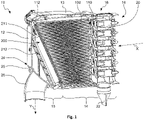
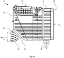
- a filter 10 can be used, for example, in an air intake tract of a construction or agricultural machine, a compressor or any other device with an internal combustion engine for filtering a fluid, in particular air.
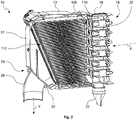
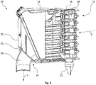
- the filter 10 has a filter housing 12 which can be roughly divided into an area 14 on the raw side and an area 16 on the clean side.
- the fluid to be filtered meets a coarse or pre-separator module 18, which in the present case is designed as a cyclone block.
- a coarse or pre-separator module 18 which in the present case is designed as a cyclone block.
- a large number of individual pre-separator cells 20 are connected in parallel in a so-called multi-cyclone block. Dust and/or water pre-separated in the cyclone block 18 is removed from the filter housing 12 through a discharge nozzle 22 .
- the main filter insert 100 has a prismatic design.
- An inflow surface 110 of the main filter insert 100 is not parallel to an outflow surface 112 of the main filter insert 100. Rather, the inflow surface 110 and the outflow surface 112 enclose an angle.
- the inflow area 110 of the main filter insert 100 is smaller in terms of its desired area than the outflow area 112 of the main filter insert 100.
- a secondary filter insert 200 is provided in the filter housing 12.
- a main inflow surface 210 of the secondary filter element 200 is aligned with the outflow surface 112 of the main filter insert 100 and, in particular, is arranged parallel to it.
- an outflow surface 212 is aligned parallel to the main inflow surface 210 of the secondary filter insert 200 . Due to the inclination of the outflow surface 112 of the main filter insert 100 , the main flow direction X is already deflected when the fluid flows out of the main filter insert 100 , but also during the flow out of the secondary filter insert 200 . Due to the outflow geometry of the filter housing 12 in the outflow area 24 , the flowing fluid is diverted to the outflow direction Y and to an outflow connector 26 . present the main outflow direction Y is essentially perpendicular to the main inflow direction X. However, other outflow directions are also conceivable. This is particularly the case in connection with the Figures 15 to 19 explained in more detail.
- the main filter insert 100 has a main filter insert inflow surface 110, a main filter insert flow direction X1, a main filter insert outflow surface 112 and a seal 116 arranged on a sealing surface 114 for the fluid-tight separation of the raw-side area 14 and the clean-side area 16 of the filter housing 12.
- a secondary filter insert 200 with a secondary filter insert inflow surface 210 , a secondary filter insert flow direction Y1 and a secondary filter insert outflow surface 212 is arranged downstream of the main filter insert 100 .
- the sealing surface 114 of the main filter insert 100 is arranged obliquely to the main flow direction Y1 of the main filter insert 100 .
- the sealing surface 114 is arranged at an angle ⁇ , which is preferably between 5° and 45° (see FIG figure 4 ), Specifically, the angle is 24° ⁇ 10° and 24° ⁇ 5°. In the present embodiment, the angle ⁇ is 24° (see figure 4 ).
- the secondary filter insert inflow surface 210 runs essentially parallel and at a distance from the sealing surface 114 of the main filter insert 100.
- the distance is less than 2 cm, in the present embodiment the distance is 1 cm.
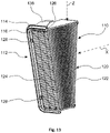
- the Figures 11 to 14 show the main filter insert 100.
- the main filter insert 100 has an inflow surface 110 and an outflow surface 112.
- the main filter insert 100 is flown against in a main flow direction X and flows through it in a main flow direction X1.
- the main filter cartridge 100 has a filter cartridge frame 118 that accommodates a filter body 120 .
- the filter body 120 is designed as a bellows.
- Fold edges 122 on the inflow side are opposite fold edges 124 on the outflow side. Fold edges 122 on the inflow side and fold edges 124 on the outflow side lie parallel, essentially perpendicular to the main flow direction X1 and in the Figures 11 to 14 essentially horizontal.
- This orientation of the fold edges 122, 124 allows the depth of the folds to be varied in the direction of an insertion direction Z.
- the main filter insert 100 can be inserted into the filter housing 12 of the filter 10 along the insertion direction Z.
- the fold height decreases along the insertion direction Z. This causes the inflow surface 110 to tilt in relation to the outflow surface 112.
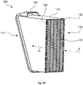
- the filter frame 118 has a sealing surface 114 along which a peripheral seal 116 is provided.
- the seal serves to separate the raw-side area 14 from the clean-side area 16 in the filter housing 12 of the filter 10 when the main filter insert 100 is inserted into the filter 10 .
- the seal 112 has a substantially U-shape in cross section.
- a web 126 which engages in the U-shape of the seal 116 is provided for reinforcement and better mechanical connection of the seal 116 to the filter frame 118 .
- the seal 116 can contact or penetrate the filter body 120, so that the filter body is bonded at the same time 120 with the filter insert frame 118 and a fluid-tight seal between the filter body 120 and the filter insert frame 118 is formed.
- the seal 116 has a spacer structure in the present case designed as a support nub 128 .
- the support knobs 128 are part of the sealing material of the seal 116.
- the support knobs 128 contact the secondary filter insert 200, in particular a secondary filter insert frame, when the main filter insert 100 and the secondary filter insert 200 are used in the filter housing 12 of the filter 10. In this state, the secondary filter insert 200 cannot move out of a sealing seat in the filter housing 12 even when there is a vibration excitation, which can be transmitted, for example, through the filter housing 12 .
- the support knobs 128 ensure that the secondary filter insert 200 is seated in the correct position in the filter housing 12 after the main filter insert 100 has been installed and the cover 13 has been closed.
- the support knobs 128 are arranged multiple times along the seal 116 on the side facing the outflow surface 112 .
- they can be made integral with the gasket 116 during manufacture of the gasket 116 .
- the seal 116 is located on the outflow surface 112 of the main filter insert 100 and acts in a direction that is perpendicular to the outflow surface 112, ie essentially axially along the main flow direction X1.
- the main filter insert 100 On its inflow side 110 , the main filter insert 100 has an edge protection 130 running around the outside of the filter frame 118 .
- the edge protection 130 is designed in such a way that when the main filter insert 100 is knocked out, for example for cleaning, impacts against the filter frame 118 can be absorbed and at least partially cushioned. In this way, breaking of the filter frame 118 or other damage to the filter insert 100, for example the filter body 120, can be avoided.
- the edge protector 130 runs around the upstream edge of the filter element 118 . In this case, individual interruptions, such as the notches 134, can be provided.
- the indentations 134 are created during the production of the edge protection 130.
- the filter frame 118 together with the filter body 120 is in a cast shell. Webs keep a distance between the casting shell bottom and the filter body 118 and allow the indentations 134 to form during the casting process.
- Recesses 136 are provided on the edge 132 on the inflow side.
- the recesses 136 break through the side walls of the filter frame 118 and thus extend perpendicular to the main flow direction X1.
- the casting material for the edge protection 130 penetrates the recesses 136, contacts the inner walls of the filter element frame 118 and in particular the filter body 120. This creates a fluid-tight seal between the filter body 120 and the filter element frame 118 and at the same time the two components are bonded.
- the edge protection 130 is thus produced in one piece with the adhesive bond between the filter body 120 and the filter insert frame 118 and a seal that is also necessary between the two components.
- the edge protection 130 can be made of a foamable polyurethane, for example. However, silicone-based material systems are also conceivable.
- the filter cartridge 100 has a handle 138 .
- the handle 138 interacts with the cover 13 of the filter 10 and ensures that the main filter insert 100 is securely seated in the filter housing 12 and at the same time exerts pressure on the seal 116, which is directed axially in the direction of the main flow direction X1, and thus ensures a tight sealing seat of the Main filter insert 100 in the filter housing 12.
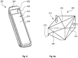
- the Figures 6 to 10 show an embodiment of a secondary filter insert 200.
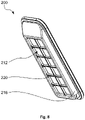
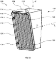
- the secondary filter insert 200 has a main inflow surface 210, an outflow surface 212 and a main flow direction Y1. Furthermore, the secondary filter insert 200 has a filter body 214 which is carried by a filter insert frame 216 . On the inflow side, the filter insert frame 216 terminates essentially flush with the filter body 214 with a frame region 218 surrounding the filter body 214 .
- the frame area 218 can, for example, serve as an abutment for the support knobs 128 of the main filter insert 100 when both filter inserts 100, 200 are in the inserted state.
- the filter body 214 is essentially cuboid. However, other basic shapes such as a prism are also conceivable.
- the filter insert frame 216 is provided with a lattice structure 220 .
- the lattice structure 220 at least partially covers the outflow surface 212 . If there is a high differential pressure between the inflow side 210 and the outflow side 212, the lattice structure 220 prevents the filter body 214 from bending or even falling through.
- the filter insert frame 216 is provided with a recessed grip 222 on a narrow side of the cuboid filter body 214 .
- the frame area 218 is widened to form a grip web 224 in the area of the recessed grip 222 .
- the width of the handle bar 224 is selected such that a fluid leaving the main filter insert outflow surface 112 can flow directly onto the filter body 214 , in particular on the side facing the recessed grip 222 . This is in particular also from the cross-sectional view of the figure 4 good to see.
- An exiting fluid can also flow directly from the uppermost edge 113 of the main filter element outflow surface 112 to the filter body 214 of the secondary filter insert 200 .
- the fluid can enter the filter body 214 in particular via the secondary inflow surface 211 .
- the filter body 214 is designed as a filter bellows.
- the fold edges run parallel to the longitudinal axis of the secondary filter insert 200 so that the end faces of the folds form the secondary inflow surface 211 .
- the folded edges of the folds form the main inflow surface 210 and the outflow surface 212.
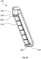
- the secondary filter insert 200 has a filter frame 216 which provides a groove 226 running around the edge of the filter body 214 on the outflow side. At the same time, a web 228 is provided on the side of the filter insert frame 216 facing the recessed grip 222 .
- the groove 226 serves as a mold for a circumferential bonding and sealing of the filter body 214 with the filter insert frame 216.
- the sealing and bonding is effected by a sealing material 230 (see figure 9 ) causes.
- the sealing material 230 can be a foaming polyurethane, for example. However, silicone-based material systems are also conceivable.
- the groove 226 and additionally the web 228 ensure good mechanical coupling of the sealing material 230 to the filter insert frame 216.
- This configuration also has the advantage that after the sealing material 230 has been introduced into the groove 226 and the filter body 214 has been inserted into the filter insert frame 216 and a subsequent foaming and curing, no further processing steps such as trimming of the sealing material 230 are necessary. Excess material can be partially absorbed by the filter body 214 or get into the intermediate area between the filter body 214 and the filter insert frame 216 without this being disadvantageous.
- the depth of the groove 226 runs essentially along the main flow direction Y1 of the secondary filter insert 200.
- the lattice structure 222 on the outflow side can be formed in one piece with the filter insert frame 216.
- the filter insert frame 216 has a seal receiving groove 232 on its inflow-side circumference.
- a seal 234 made of foam rubber, for example, can be inserted into this seal receiving groove 232 .
- the seal 234 thus acts radially, i.e. perpendicular to the main flow direction Y1 of the secondary filter insert 200.
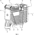
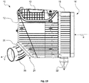
- the Figures 15 to 19 show the filter 10 with different orientations of the outflow connector 26.
- the filter housing 12 of the filter 10 has a fastening area 25 in the outflow area 24.
- the fastening area 25 encloses an angle of approximately 45° with the main inflow direction X of the filter housing 12 .
- the outflow connector 26 can be fastened to the fastening area 25 .
- the outflow socket 26 is shaped in such a way that a fluid flowing through the outflow socket 26 is deflected by 45°.
- the outflow socket 46 can be attached in a rotatable manner to the fastening surface 25 before it is finally fastened.
- the final deflection direction or outflow direction Y of the filter 10 can thus only be determined at a very late point in time during the manufacture of the filter 10 .
- a deflection of 90° ( figure 17 ) as well as angle ranges in between are possible. In the angular ranges lying between the extreme angles, there is an additional lateral deflection.
Landscapes
- Engineering & Computer Science (AREA)
- Chemical & Material Sciences (AREA)
- Combustion & Propulsion (AREA)
- Mechanical Engineering (AREA)
- General Engineering & Computer Science (AREA)
- Chemical Kinetics & Catalysis (AREA)
- Manufacturing & Machinery (AREA)
- Filtering Of Dispersed Particles In Gases (AREA)
- Filtration Of Liquid (AREA)
- Lubrication Details And Ventilation Of Internal Combustion Engines (AREA)
- Separation By Low-Temperature Treatments (AREA)
- Water Treatment By Sorption (AREA)
Description
Die vorliegende Erfindung betrifft einen Filter, insbesondere für Brennkraftmaschinen, zur Filterung eines Fluids, insbesondere von Luft sowie einen Filtereinsatz, insbesondere für einen solchen Filter.The present invention relates to a filter, in particular for internal combustion engines, for filtering a fluid, in particular air, and a filter insert, in particular for such a filter.
Es sind aus
Bei einem Einsatz in Bau- oder Landmaschinen werden in unterschiedlichen Betriebszuständen Vibrationen auf den Filter übertragen. Es ist deshalb ein vorrangiges Ziel, den Hauptfiltereinsatz vibrationsfest im Filter anzuordnen. Aber auch bei einem stromabwärts angeordneten Sekundärfiltereinsatz ist während des Betriebs ein sicherer Sitz bedeutsam.When used in construction or agricultural machinery, vibrations are transmitted to the filter in different operating states. It is therefore a primary goal to arrange the main filter insert in the filter so that it is vibration-proof. However, a secure fit during operation is also important in the case of a secondary filter insert arranged downstream.
Es ist eine Aufgabe der Erfindung, einen Filter, insbesondere für Brennkraftmaschinen, zur Filterung eines Fluids, insbesondere von Luft, anzugeben, der auch unter extremen Einsatzbedingung eine hohe Zuverlässigkeit aufweist.It is an object of the invention to specify a filter, in particular for internal combustion engines, for filtering a fluid, in particular air, which has a high level of reliability even under extreme conditions of use.
Bei den genannten Einsatzbereichen ist es notwendig, die Gesamtkonstruktion eines Filtereinsatzes so robust wie möglich zu gestalten. Vordringlich ist ein Schutz des Filtermediums im Betrieb. Bei der Auslegung derartige Filtereinsätze ist auch auf etwaige Handhabungsgewohnheiten bei einem Wechsel des Filtereinsatzes oder bei einer Wartung Rücksicht zu nehmen.In the areas of application mentioned, it is necessary to make the overall construction of a filter insert as robust as possible. Protection of the filter medium during operation is a priority. When designing such filter inserts, any handling habits when changing the filter insert or during maintenance must also be taken into account.
Es ist somit eine weitere Aufgabe der Erfindung, einen Filtereinsatz anzugeben, der auch bei extremen Einsatzbedingungen und Handhabungsgewohnheiten eine zuverlässige Filterfunktion gewährleistet.It is therefore a further object of the invention to specify a filter insert which ensures a reliable filter function even under extreme conditions of use and handling habits.
Für Einsatz in Fahrzeugen, die wenig Bauraum für Filtrationszwecke bieten, werden im Allgemeinen sogenannte Kompaktluftfilter eingesetzt, die inline durchströmbar sind. Dies bedeutet, dass die Anströmrichtung und die Abströmrichtung parallel verlaufen und im Wesentlichen miteinander fluchten. Oftmals muss die aus dem Luftfilter abströmende Luft je nach Anwendungsfall nach dem Durchströmen des Filters umgelenkt werden. Hierzu kann beispielsweise ein Rohrkrümmer dem Filtergehäuse nachgeschaltet sein. Derartige nachgeschaltete Bauteile erhöhen jedoch wiederum den Bauraumbedarf der gesamten Anordnung.For use in vehicles that offer little installation space for filtration purposes, so-called compact air filters are generally used, which can be flowed through inline. This means that the inflow direction and the outflow direction run parallel and are essentially aligned with one another. Depending on the application, the air flowing out of the air filter often has to be deflected after it has flowed through the filter. For this purpose, for example, a pipe elbow can be connected downstream of the filter housing be. However, downstream components of this type in turn increase the space required for the entire arrangement.
Es ist eine weitere Aufgabe der Erfindung, einen Filter, insbesondere für Brennkraftmaschinen, zur Filterung eines Fluids, insbesondere von Luft, anzugeben, der bei vergleichbarer Filterleistung weniger Bauraum beansprucht.A further object of the invention is to specify a filter, in particular for internal combustion engines, for filtering a fluid, in particular air, which takes up less installation space for a comparable filter performance.
Die oben genannten Aufgaben werden jeweils durch verschiedene Aspekte der im Folgenden beschriebenen Ausführungsformen eines Filters, insbesondere für Brennkraftmaschinen, zur Filterung eines Fluids, insbesondere von Luft sowie eines Filtereinsatzes, insbesondere für einen solchen Filter gelöst. Die verschiedenen Aspekte können wie aus den Ausführungsbeispielen ersichtlich einzeln oder kombiniert vorteilhaft in Ausführungsformen enthalten sein, wobei bei Kombination einzelne Aspekte die Vorteile anderer Aspekte unterstützen und ein synergistisches Zusammenwirken zu einem vorteilhaften Produkt führt.The above-mentioned objects are each achieved by various aspects of the embodiments of a filter described below, in particular for internal combustion engines, for filtering a fluid, in particular air, and a filter insert, in particular for such a filter. As can be seen from the exemplary embodiments, the various aspects can advantageously be contained individually or in combination in embodiments, with the combination of individual aspects supporting the advantages of other aspects and synergistic interaction leading to an advantageous product.
Die Aufgabe wird durch einen Filtereinsatz für einen Filter zur Filterung eines Fluids, insbesondere von Luft, insbesondere für eine Brennkraftmaschine gemäß Anspruch 1 gelöst. Weitere Ausgestaltungen der Erfindung sind in den Unteransprüchen angegeben.The object is achieved by a filter insert for a filter for filtering a fluid, in particular air, in particular for an internal combustion engine according to claim 1. Further developments of the invention are specified in the dependent claims.
Der erfindungsgemäße Filtereinsatz weist eine Anströmfläche, eine Abströmfläche sowie eine Hauptströmungsrichtung, einen Filterkörper und einen den Filterkörper tragenden Filtereinsatzrahmen auf. Der Filtereinsatzrahmen weist im Bereich der Abströmfläche eine Dichtung zur Trennung eines Filterinnenraums in Reinseite und Rohseite und eine Abstandsstruktur zur Festlegung eines Abstands zwischen dem Filtereinsatzrahmen und einem in Hauptströmungsrichtung stromabwärts anordenbaren weiteren Filtereinsatz auf. Mittels der Abstandstruktur wird ein vorher festgelegter Abstand zwischen Filtereinsatz, der beispielsweise ein Hauptfiltereinsatz sein kann, und einem stromabwärts angeordneten weiteren Filtereinsatz, der beispielsweise ein Sekundärfiltereinsatz sein kann, auch unter extremen Einsatzbedingungen wie beispielsweise Vibrationen aufrechterhalten. Dies sorgt dafür, dass der weitere Filtereinsatz sich nicht aus seiner vorgesehenen Position heraus bewegen und damit seine Dichtfunktion und Sicherungsfunktion verlieren kann.The filter insert according to the invention has an inflow surface, an outflow surface and a main flow direction, a filter body and a filter insert frame carrying the filter body. In the area of the outflow surface, the filter insert frame has a seal for separating a filter interior into the clean side and dirty side and a spacer structure for defining a distance between the filter insert frame and a further filter insert that can be arranged downstream in the main flow direction. By means of the spacer structure, a predetermined distance between the filter cartridge, which can be a main filter cartridge, for example, and a further filter cartridge arranged downstream, which can be a secondary filter cartridge for example, is maintained even under extreme operating conditions such as vibrations. This ensures that the further filter insert cannot move out of its intended position and thus lose its sealing and safety function.
Gemäß der Erfindung ist vorgesehen, dass die Abstandsstruktur innerhalb der Dichtung, mehrfach entlang der Dichtung und insbesondere am Umfang der Abströmfläche angeordnet ist. Bei einer solchen Ausgestaltung kann es vorgesehen sein, dass der Außenumfang senkrecht zur Hauptströmungsrichtung des weiteren Filtereinsatzes in Form und Größe der Dichtung folgt und somit eine Abstützfläche für die Abstandsstruktur bietet.According to the invention, it is provided that the spacer structure is arranged within the seal, multiple times along the seal and in particular on the circumference of the outflow surface. In such an embodiment, it can be provided that the outer circumference follows the shape and size of the seal perpendicularly to the main flow direction of the further filter insert and thus offers a support surface for the spacer structure.
Eine vorteilhafte Ausführung der Erfindung sieht vor, dass die Abströmfläche oder/und eine Dichtfläche der Dichtung mit der Hauptströmungsrichtung einen Winkel zwischen 5° und 45°, insbesondere einen Winkel von 24°±10° und insbesondere einen Winkel von 24°±5° einschließt. Eine derart zur Hauptströmungsrichtung gewinkelte Abströmfläche besitzt eine größere Fläche als die Abströmfläche. Generell bietet die Abwicklung der Abströmfläche oder/und der Dichtfläche die Möglichkeit, bereits eine Umlenkung der Hauptströmungsrichtung innerhalb des Filtereinsatzes oder direkt nachfolgend dem Filtereinsatz vorzunehmen. Dies spart Bauraum und verbessert aufgrund kürzerer Strömungsstrecken den Druckverlust innerhalb des Filters.An advantageous embodiment of the invention provides that the outflow surface and/or a sealing surface of the seal is at an angle of between 5° and 45°, in particular one, with the main flow direction includes an angle of 24°±10° and in particular an angle of 24°±5°. An outflow surface angled in this way to the main flow direction has a larger area than the outflow surface. In general, the development of the outflow surface and/or the sealing surface offers the possibility of already deflecting the main direction of flow within the filter insert or directly downstream of the filter insert. This saves installation space and improves the pressure loss within the filter due to shorter flow paths.
Erfindungsgemäß ist die Abstandsstruktur integral mit der Dichtung ausgebildet, nämlich in die Dichtung eingeformt. Dies ermöglicht beispielsweise die Verwendung des gleichen Materials und die Herstellung der Abstandsstruktur im gleichen Arbeitsschritt wie die Dichtung.According to the invention, the spacer structure is formed integrally with the seal, namely molded into the seal. This makes it possible, for example, to use the same material and to manufacture the spacer structure in the same work step as the seal.
Eine besonders bevorzugte Ausführungsform sieht vor, dass die Abstandsstruktur dazu ausgelegt ist, im eingebauten Zustand des Filtereinsatzes eine Spann- oder Haltekraft auf einen in Hauptströmungsrichtung stromabwärts anordenbaren weiteren Filtereinsatz, insbesondere einen Sekundärfiltereinsatz, auszuüben, wobei die Kraft den weiteren Filtereinsatz in seine Einbauposition drückt. Dies kann beispielsweise dadurch erreicht werden, dass die Abstandsstruktur aus einem elastischen Material hergestellt ist. Wird der Filtereinsatz dann nach dem weiteren Filtereinsatz eingesetzt, kann durch die geeignete Wahl einer entsprechenden Geometrie bereits das Einsetzen eine Kraft auf den weiteren Filtereinsatz ausüben. Dies verbessert wiederum die Zuverlässigkeit des Filters, da der weitere Filtereinsatz dauerhaft einer Kraft ausgesetzt ist, die ihn an seinem vorgesehenen Platz hält.A particularly preferred embodiment provides that the spacer structure is designed to exert a clamping or holding force on a further filter insert that can be arranged downstream in the main flow direction, in particular a secondary filter insert, when the filter insert is installed, with the force pressing the further filter insert into its installation position. This can be achieved, for example, by the spacer structure being made of an elastic material. If the filter insert is then inserted after the further filter insert, the insertion can already exert a force on the further filter insert through the suitable choice of a corresponding geometry. This in turn improves the reliability of the filter since the further filter cartridge is constantly subjected to a force that holds it in place.
Gemäß der Erfindung wirkt die Dichtung axial in Richtung der Hauptströmungsrichtung. Dies bedeutet, dass die zur Abdichtung aufzubringende Kraft parallel zur Abströmungsrichtung verläuft.According to the invention, the seal acts axially in the direction of the main flow direction. This means that the force to be applied for sealing runs parallel to the outflow direction.
Bei einer Ausführungsform der Erfindung ist der Filterkörper als Filterbalg, insbesondere mit variabler Faltenhöhe, ausgebildet. Mittels der variablen Faltenhöhe kann beispielsweise eine schräg zur Hauptströmungsrichtung verlaufende Abströmfläche realisiert werden. Als variable Faltenhöhe wird ein Aufbau eines zickzackförmig gefalteten Filterkörpers verstanden, bei welchem die Faltenhöhen über eine durch die Aneinanderreihung von Faltkanten definierte Länge des Faltenbalges nicht konstant ist, sondern sich kontinuierlich oder diskontinuierlich ändert oder in benachbarten Abschnitten unterscheidet. Bevorzugt ändert sich die Höhe der Falten kontinuierlich und weiter bevorzugt linear über die Länge des Balges.In one embodiment of the invention, the filter body is designed as a filter bellows, in particular with a variable fold height. By means of the variable fold height, for example, an outflow surface running obliquely to the main flow direction can be realized. A variable fold height is a structure of a zigzag folded filter body in which the fold height is not constant over a length of the bellows defined by the stringing together of fold edges, but changes continuously or discontinuously or differs in adjacent sections. The height of the folds preferably changes continuously and more preferably linearly over the length of the bellows.
Die Aufgabe wird auch durch einen Filter zur Filterung eines Fluids, insbesondere von Luft, insbesondere für eine Brennkraftmaschine gelöst. Der erfindungsgemäße Filter weist ein Filtergehäuse auf, in den ein Hauptfiltereinsatz und ein Sekundärfiltereinsatz einsetzbar sind. Der Hauptfiltereinsatz weist eine Anströmfläche, eine Abströmfläche sowie eine Hauptströmungsrichtung, einen Filterkörper und einen den Filterkörper tragenden Filtereinsatzrahmen auf. Der Sekundärfiltereinsatz ist stromabwärts des Hauptfiltereinsatzes anordenbar. Der Filtereinsatzrahmen weist im Bereich der Abströmfläche eine Dichtung zur Trennung des Filtergehäuses in Reinseite und Rohseite sowie eine Abstandsstruktur zur Festlegung eines Abstands zwischen dem Filtereinsatzrahmen und dem Sekundärfiltereinsatz auf.The object is also achieved by a filter for filtering a fluid, in particular air, in particular for an internal combustion engine. The filter according to the invention has a filter housing into which a main filter insert and a secondary filter insert can be inserted. The main filter insert has an inflow surface, an outflow surface and a main flow direction, a filter body and a filter insert frame carrying the filter body. The secondary filter insert can be arranged downstream of the main filter insert. In the area of the outflow surface, the filter insert frame has a seal for separating the filter housing into the clean side and the dirty side, as well as a spacer structure for defining a distance between the filter insert frame and the secondary filter insert.
Bei einer erfindungsgemäßen Ausführungsform des Filters ist vorgesehen, dass das Filtergehäuse eine Einführrichtung aufweist, die im Wesentlichen senkrecht zur Hauptströmungsrichtung liegt. Dies ermöglicht nach dem Einsetzen des Sekundärfiltereinsatzes ein Einsetzen des Hauptfiltereinsatzes derart, dass der Sekundärfiltereinsatz gegen ein Herausbewegen aus seinem vorgesehenen Sitz blockiert ist.In an embodiment of the filter according to the invention, it is provided that the filter housing has an insertion direction that is essentially perpendicular to the main flow direction. After the secondary filter insert has been inserted, this enables the main filter insert to be inserted in such a way that the secondary filter insert is blocked from moving out of its intended seat.
Bei einer bevorzugten Ausführungsform ist vorgesehen, dass der Sekundärfiltereinsatz eine Dichtung zur Anlage an dem Filtergehäuse aufweist, wobei die Dichtung insbesondere radial zur Durchströmungsrichtung des Sekundärfiltereinsatzes wirkend ausgelegt ist. Es ist somit nicht notwendig, in axialer Verlängerung zur Hauptdurchströmungsrichtung des Sekundärfiltereinsatzes am Filtergehäuse eine Dichtfläche vorzusehen. Vielmehr wirkt die Dichtung senkrecht zur Hauptdurchströmungsrichtung gegen das Filtergehäuse bereits beim Einsetzen in den vorgesehenen Sitz.In a preferred embodiment, it is provided that the secondary filter insert has a seal for contact with the filter housing, the seal being designed to act in particular radially to the flow direction of the secondary filter insert. It is therefore not necessary to provide a sealing surface on the filter housing in an axial extension to the main flow direction of the secondary filter insert. Rather, the seal acts perpendicularly to the main direction of flow against the filter housing as soon as it is inserted into the intended seat.
Gemäß einer Ausführungsform der Erfindung weist der Sekundärfiltereinsatz einen Sekundärfilterkörper und einen den Sekundärfilterkörper tragenden Sekundärfiltereinsatzrahmen auf. Dabei kann es vorgesehen sein, dass im eingesetzten Zustand des Hauptfiltereinsatzes und des Sekundärfiltereinsatzes die Abstandsstruktur des Hauptfiltereinsatzes die Dichtung oder den Sekundärfiltereinsatzrahmen des Sekundärfiltereinsatzes kontaktiert. Somit ist bei im Einsatzfall auftretenden Vibrationen ein Herausbewegen des Sekundärfiltereinsatzes nicht möglich, da die Abstandsstruktur des Hauptfiltereinsatzes den Raum, über den der Sekundärfiltereinsatz eingesetzt wurde, blockiert.According to one embodiment of the invention, the secondary filter insert has a secondary filter body and a secondary filter insert frame carrying the secondary filter body. Provision can be made for the spacer structure of the main filter insert to contact the seal or the secondary filter insert frame of the secondary filter insert when the main filter insert and the secondary filter insert are in the inserted state. Thus, in the event of vibrations occurring during use, it is not possible for the secondary filter insert to be moved out, since the spacer structure of the main filter insert blocks the space over which the secondary filter insert was inserted.
In einer weiteren Ausführungsform, die auch eigenständig eine Erfindung darstellt, weist der erfindungsgemäße Filtereinsatz für einen Filter zur Filterung eines Fluids, insbesondere von Luft, insbesondere für eine Brennkraftmaschine eine Anströmfläche, eine Abströmfläche, eine Hauptströmungsrichtung, einen Filterkörper sowie einen den Filterkörper tragenden Filtereinsatzrahmen auf. Der Filtereinsatzrahmen weist im Bereich der Abströmfläche eine Dichtung zur Trennung eines Filterinnenraums eines Filter in Reinseite und Rohseite und im Bereich der Anströmfläche einen außen um den Filterrahmen umlaufenden Kantenschutz auf. Der Kantenschutz verbindet den Filterkörper und den Filtereinsatzrahmen miteinander. Erfindungsgemäß ergibt sich somit ein synergistisches Zusammenwirken aus Kantenschutz und der Verbindung des Filterkörpers mit dem Filtereinsatzrahmen. Dies ist besonders vorteilhaft bei der gängigen Praxis im Baumaschinensektor, Filtereinsätze durch Ausblasen oder Ausklopfen ab zu reinigen.In a further embodiment, which also represents an invention in its own right, the filter insert according to the invention for a filter for filtering a fluid, in particular air, in particular for an internal combustion engine, has an inflow surface, an outflow surface, a main flow direction, a filter body and a filter insert frame carrying the filter body . In the area of the outflow surface, the filter insert frame has a seal for separating a filter interior of a filter into the clean side and dirty side, and in the area of the inflow surface an edge protection that runs around the outside of the filter frame. The edge protection connects the filter body and the filter insert frame with each other. According to the invention, there is thus a synergistic interaction of edge protection and the connection of the filter body to the filter insert frame. This is particularly advantageous given the common practice in the construction machinery sector of cleaning filter inserts by blowing them out or knocking them out.
Insbesondere ist bei besonders bevorzugter Ausführungsform vorgesehen, dass der Kantenschutz eine für das zu filternde Fluid dichte Verbindung zwischen Filterkörper und Filtereinsatzrahmen bildet. Somit bildet die Verbindung aus Filterkörper und Filtereinsatzrahmen gleichzeitig die Abdichtung des Filterkörpers gegenüber dem Filtereinsatzrahmen.In particular, it is provided in a particularly preferred embodiment that the edge protection forms a connection between the filter body and the filter insert frame that is sealed for the fluid to be filtered. The connection between the filter body and the filter insert frame thus forms the seal between the filter body and the filter insert frame at the same time.
Bei einer erfindungsgemäßen Weiterbildung der Erfindung ist vorgesehen, dass der Filtereinsatzrahmen im Bereich des Kantenschutzes Ausnehmungen aufweist, die von dem Kantenschutz ausgefüllt sind. Dies ermöglicht eine besonders gute mechanische Verbindung zwischen dem Kantenschutz und dem Filtereinsatzrahmen.In a development of the invention according to the invention, it is provided that the filter insert frame has recesses in the area of the edge protection, which are filled by the edge protection. This enables a particularly good mechanical connection between the edge protection and the filter insert frame.
Besonders bevorzugt erstrecken sich die Ausnehmungen senkrecht zur Hauptströmungsrichtung. Es ist somit nicht notwendig, in dem Filtereinsatzrahmen eine Abwicklung für den Kantenschutz vorzusehen. Vielmehr kann der Kantenschutz vollständig um die anströmungsseitigen Kanten des Filtereinsatzrahmens herum liegen und gleichzeitig den Filtereinsatzrahmen durch die Ausnehmungen durchdringen und so eine besonders mechanisch stabile Verbindung einzugehen.The recesses particularly preferably extend perpendicularly to the main direction of flow. It is therefore not necessary to provide a development for the edge protection in the filter insert frame. Rather, the edge protection can lie completely around the edges of the filter insert frame on the inflow side and at the same time penetrate the filter insert frame through the recesses and thus enter into a particularly mechanically stable connection.
Bei einer Ausgestaltung der Erfindung umgibt der Filtereinsatzrahmen den Filterkörper. Zusätzlich bestimmt der Filtereinsatzrahmen die Hauptströmungsrichtung des Filtereinsatzes.In one embodiment of the invention, the filter insert frame surrounds the filter body. In addition, the filter insert frame determines the main flow direction of the filter insert.
Eine besonders bevorzugte Ausführungsform der Erfindung sieht vor, dass der Kantenschutz den Filterkörper teilweise durchdringt. Somit ergibt sich nach dem Aushärten des Kantenschutzes eine besonders stabile Verbindung zwischen dem Kantenschutz und dem Filtereinsatzrahmen einerseits und dem Filtereinsatzrahmen und dem Filterkörper andererseits.A particularly preferred embodiment of the invention provides that the edge protection partially penetrates the filter body. Thus, after the edge protection has hardened, a particularly stable connection results between the edge protection and the filter insert frame on the one hand and the filter insert frame and the filter body on the other hand.
Eine Weiterbildung der Erfindung sieht vor, dass der Filterkörper als Filterbalg, insbesondere mit variabler Faltenhöhe, ausgebildet ist. Die variable Faltenhöhe ermöglicht eine Abwinklung zwischen Abströmfläche und Hauptströmungsrichtung.A development of the invention provides that the filter body is designed as a filter bellows, in particular with a variable fold height. The variable pleat height enables an angle between the outflow surface and the main flow direction.
Erfindungsgemäß kann vorgesehen sein, dass die Abströmfläche oder/und eine Dichtfläche der Dichtung mit der Hauptströmungsrichtung einen Winkel zwischen 5° und 45°, insbesondere einen Winkel von 24°±10° und insbesondere einen Winkel von 24°±5° einschließt. Der Winkel zwischen Hauptströmungsrichtung und Abströmfläche oder Dichtfläche erlaubt eine besonders kompakte Bauweise, da eine Umlenkung der Hauptausrichtung bereits innerhalb eines den Filtereinsatz aufnehmenden Filtergehäuses erfolgen kann.According to the invention, it can be provided that the outflow surface and/or a sealing surface of the seal encloses an angle of between 5° and 45°, in particular an angle of 24°±10° and in particular an angle of 24°±5°, with the main flow direction. The angle between the main direction of flow and the outflow surface or sealing surface allows for a particularly compact design, since the main orientation can be deflected within a filter housing accommodating the filter insert.
Eine besonders bevorzugte Weiterbildung der Erfindung sieht vor, dass die Verbindung zwischen Filterkörper und Filtereinsatzrahmen eine Verklebung ist, die einteilig mit dem Kantenschutz ausgebildet ist. Insbesondere können die Verklebung und der Kantenschutz aus dem gleichen Material, insbesondere aus einem Polyurethan, gebildet sein. Dies ermöglicht insbesondere bei der Herstellung technische Vorteile, da die Verklebung zwischen dem Filtereinsatzrahmen und dem Filterkörper, die Abdichtung zwischen Filterkörper und Filtereinsatzrahmen und der Kantenschutz in einem Arbeitsschritt hergestellt werden können und gleichzeitig eine besonders robuste Ausführungsform entsteht.A particularly preferred development of the invention provides that the connection between the filter body and the filter insert frame is an adhesive bond that is formed in one piece with the edge protection. In particular, the bond and the edge protection can be formed from the same material, in particular from a polyurethane. This enables technical advantages, particularly in production, since the bond between the filter element frame and the filter body, the seal between the filter body and filter element frame and the edge protection can be produced in one work step and at the same time a particularly robust embodiment is created.
Erfindungsgemäß ist der Kantenschutz so ausgelegt, dass die bei einem Ausklopfen des Filtereinsatzes auftretenden Kräfte durch den Kantenschutz zumindest teilweise aufgenommen werden können und insbesondere eine Beschädigung des Filtereinsatzes verhindert werden kann.According to the invention, the edge protection is designed in such a way that the forces occurring when the filter insert is knocked out can be at least partially absorbed by the edge protection and, in particular, damage to the filter insert can be prevented.
Der erfindungsgemäße Filtereinsatz weist bevorzugt eine prismatische Grundform auf, wobei die parallel zueinander angeordneten Grundfläche und Deckfläche eine polygone Grundform aufweisen. Der Filtereinsatz weist entsprechend der polygonen Grundform der Grund- und Deckflächen zumindest drei, bevorzugt vier Mantelflächen auf. Eine erste Mantelfläche ist benachbart einer zweiten Mantelfläche. Sowohl die erste Mantelfläche als bevorzugt auch die zweite Mantelfläche sind Anströmflächen. Alternativ sind die erste Mantelfläche und bevorzugt zusätzlich die zweite Mantelfläche Abströmflächen. Die erste Mantelfläche und die zweite Mantelfläche stehen in Wesentlichen zueinander senkrecht. Mit im Wesentlichen ist ein Winkelbereich von 80° bis 100° umfasst. Eine dritte Mantelfläche liegt der ersten Mantelfläche bevorzugt im Wesentlichen gegenüber bzw. ist von dieser in Durchströmungsrichtung beabstandet und ist im Gegensatz zu der ersten und zweiten Mantelfläche eine Abströmfläche, wenn die erste und die zweite Mantelfläche Anströmflächen sind oder die dritte Mantelfläche ist eine Anströmfläche, wenn die erste und bevorzugt die zweite Mantelfläche Abströmflächen sind. Die dritte Mantelfläche schließt mit der ersten Mantelfläche einen Winkel ein, der kleiner 80° und größer 10° ist und sich insbesondere zwischen 70° und 20° befindet. Besonders bevorzugt sind Winkel wie 45° oder 60°.The filter insert according to the invention preferably has a prismatic basic shape, with the base surface and top surface arranged parallel to one another having a polygonal basic shape. Corresponding to the basic polygonal shape of the base and cover surfaces, the filter insert has at least three, preferably four, lateral surfaces. A first lateral surface is adjacent to a second lateral surface. Both the first lateral surface and preferably also the second lateral surface are inflow surfaces. Alternatively, the first lateral surface and preferably also the second lateral surface are outflow surfaces. The first lateral surface and the second lateral surface are essentially perpendicular to one another. An angular range of 80° to 100° is essentially included. A third lateral surface is preferably essentially opposite the first lateral surface or is spaced from it in the direction of flow and, in contrast to the first and second lateral surface, is an outflow surface if the first and second lateral surface are inflow surfaces or the third lateral surface is an inflow surface if the first and preferably the second lateral surface are outflow surfaces. The third lateral surface encloses an angle with the first lateral surface which is less than 80° and greater than 10° and is in particular between 70° and 20°. Angles such as 45° or 60° are particularly preferred.
Im Folgenden wird die oben erwähnte erste Alternative beschrieben, bei der die erste und bevorzugt auch die zweite Mantelfläche Anströmflächen sind und die dritte Mantelfläche Abströmfläche ist. Die Ausführungen geltend entsprechend für den umgekehrten Fall der zweiten Alternative, bei dem die erste und die zweite Mantelfläche Abströmfläche und die dritte Mantelfläche Anströmfläche sind. Bei der beschriebenen Filtereinsatzgeometrie ergibt sich in der Regel eine Mantelfläche als Anströmfläche, die zuerst von dem Hauptfluidstrom getroffen wird. Die zweite Mantelfläche unterstützt das Eintreten des Fluids in den Filtereinsatz und vergrößert die Anströmfläche. Über die dritte Mantelfläche strömt das Fluid ab. Dadurch, dass die dritte Mantelfläche zur ersten Mantelfläche geneigt ist, ergibt sich für einen Filter mit einem solchen Filtereinsatz die Möglichkeit, die Abströmrichtung bereits innerhalb des Filtergehäuses in der gewünschten Art festzulegen. Eine externe Umlenkung außerhalb des Filtergehäuses beispielsweise mittels eines gekrümmten Abströmstutzens ist nicht mehr notwendig. Es werden somit zwei Vorteile erzielt. Einerseits ergibt sich eine deutlich vergrößerte Anströmfläche, welche eine unter Umständen bessere Ausnutzung der Filterkapazität ermöglicht. Gleichzeitig erlaubt die erfindungsgemäße Filtergeometrie eine Umlenkung der Hauptströmungsrichtung innerhalb des Filtereinsatzes, wodurch der durch den Filter beanspruchte Bauraum optimiert, das heißt verkleinert werden kann.The first alternative mentioned above is described below, in which the first and preferably also the second lateral surface are inflow surfaces and the third lateral surface is an outflow surface. The explanations apply correspondingly to the reverse case of the second alternative, in which the first and the second lateral surface are the outflow surface and the third lateral surface are the inflow surface. In the case of the filter insert geometry described, there is generally a lateral surface as the inflow surface which is hit first by the main fluid flow. The second lateral surface supports the entry of the fluid into the filter insert and increases the inflow surface. The fluid flows off via the third lateral surface. The fact that the third lateral surface is inclined relative to the first lateral surface results in the possibility for a filter with such a filter insert of already defining the outflow direction in the desired manner inside the filter housing. An external deflection outside of the filter housing, for example by means of a curved outflow nozzle, is no longer necessary. Two advantages are thus achieved. On the one hand, there is a significantly larger inflow area, which under certain circumstances enables better utilization of the filter capacity. At the same time, the filter geometry according to the invention allows the main flow direction to be deflected within the filter insert, as a result of which the installation space required by the filter can be optimized, ie reduced.
Als Hauptströmungsrichtung wird die gemittelte Richtung der Strömung an einer Position des Weges durch das Filtersystem und/oder Filterelement verstanden. Beispielsweise ist die Hauptströmungsrichtung innerhalb eines Zyklonblocks aus einer Vielzahl von Inline-Zyklonzellen definiert durch die axiale Erstreckung der Zyklonzellen. Beim Auftreffen auf die Anströmfläche eines Filterelements wird die Hauptströmungsrichtig im Wesentlichen senkrecht zu dieser Anströmfläche stehen und im Übrigen durch den Weg des geringsten Widerstandes definiert.The main direction of flow is understood to be the average direction of the flow at a position along the path through the filter system and/or filter element. For example, the main direction of flow within a cyclone block made up of a large number of inline cyclone cells is defined by the axial extension of the cyclone cells. When impinging on the face of a filter element, the main flow will properly be substantially perpendicular to that face and otherwise defined by the path of least resistance.
Gemäß einer Ausführungsform ist die polygone Grundform ein Dreieck, ein Viereck oder ein Fünfeck. Die sich ergebende prismatische Grundform kann je nach Anwendungsfall auch leicht gewölbte Mantelflächen aufweisen. Zudem kann auch eine Anströmung oder Abströmung über die Grund- und/oder Deckfläche des Prismas erfolgen.According to one embodiment, the basic polygonal shape is a triangle, a square or a pentagon. Depending on the application, the resulting prismatic basic shape can also have slightly curved lateral surfaces exhibit. In addition, an inflow or outflow can also take place via the base and/or top surface of the prism.
Eine bevorzugte Weiterbildung der Erfindung sieht vor, dass der Filtereinsatz einen Filterkörper mit einem zickzackförmig gefalteten Filtermedium aufweist. Ein derart gefaltetes Filtermedium besitzt eine hohe Oberfläche und lässt sich verhältnismäßig kostengünstig in die gewünschte Grundform bringen.A preferred further development of the invention provides that the filter insert has a filter body with a filter medium folded in a zigzag shape. A filter medium folded in this way has a large surface area and can be brought into the desired basic shape relatively inexpensively.
Eine Ausgestaltung sieht vor, dass die Falten äußere Faltkanten aufweisen, die auf der ersten Mantelfläche liegen und den äußeren Faltkanten gegenüberliegende innere Faltkanten aufweisen, die auf der dritten Mantelfläche liegen. Es erfolgt somit eine Anströmung des Filtereinsatzes im Wesentlichen senkrecht zu den Faltkanten. Gleiches gilt für die Abströmung, wobei die dritte Mantelfläche gegenüber der ersten Mantelfläche geneigt ist.One embodiment provides that the folds have outer fold edges that lie on the first lateral surface and inner fold edges that lie opposite the outer fold edges and lie on the third lateral surface. There is thus a flow of the filter insert essentially perpendicular to the fold edges. The same applies to the outflow, with the third lateral surface being inclined relative to the first lateral surface.
Bei der beschriebenen zickzackförmigen Faltung des Filtermediums weisen die Falten zumindest eine Stirnseite auf, die auf der zweiten Mantelfläche zu liegen kommt. Es erfolgt somit die Anströmung des Filtermediums sowohl über die Faltkante als auch über die Stirnseite der Falte. Die Stirnseiten müssen in diesem Fall so ausgestaltet sein, dass keine direkte Zuströmung zur Reinseite des Filtereinsatzes erfolgen kann.With the described zigzag folding of the filter medium, the folds have at least one end face that comes to rest on the second lateral surface. The inflow of the filter medium thus takes place both over the fold edge and over the front side of the fold. In this case, the end faces must be designed in such a way that there is no direct inflow to the clean side of the filter insert.
Eine besonders bevorzugte Ausführungsform der Erfindung sieht vor, dass sich die Tiefe benachbarter Faltkanten unterscheidet und insbesondere jede zweite Falte die gleiche Tiefe aufweist. Die unterschiedliche Tiefe benachbarter Faltkanten ermöglicht eine Anschrägung des Filtereinsatzes und so die Ausbildung der gewünschten Geometrie.A particularly preferred embodiment of the invention provides that the depth of adjacent fold edges differs and in particular every second fold has the same depth. The different depths of adjacent folded edges allow the filter insert to be beveled and thus the formation of the desired geometry.
Eine besonders bevorzugte Ausführungsform der Erfindung sieht vor, dass die Falten je zwei Stirnseiten aufweisen. Eine Stirnseite der Falten liegt auf der zweiten Mantelfläche. Die andere Stirnseite der Falten liegt auf einer vierten Mantelfläche. Die zweite Mantelfläche ist größer als die vierte Mantelfläche. Die vierte Mantelfläche weist mehr Faltkanten auf als die zweite Mantelfläche, insbesondere doppelt so viele. Durch die Verdopplung der Faltkanten an der vierten Mantelfläche ist es möglich, den Winkel zwischen der dritten Mantelfläche und der ersten Mantelfläche her- und einzustellen.A particularly preferred embodiment of the invention provides that the folds each have two end faces. An end face of the folds lies on the second lateral surface. The other face of the folds lies on a fourth lateral surface. The second lateral surface is larger than the fourth lateral surface. The fourth lateral surface has more folding edges than the second lateral surface, in particular twice as many. By doubling the folding edges on the fourth lateral surface, it is possible to produce and set the angle between the third lateral surface and the first lateral surface.
Der Erfindungsgedanke findet auch Niederschlag in einem Filter mit einem erfindungsgemäßen Filtereinsatz. In einem solchen Filter kann vorgesehen sein, dass die Hauptanströmrichtung des Filters und die Hauptabströmrichtung des Filters einen Winkel von mehr als 30°, insbesondere mehr als 45° bevorzugt mehr als 60° und insbesondere 90° einschließen.The idea of the invention is also reflected in a filter with a filter insert according to the invention. In such a filter it can be provided that the main inflow direction of the filter and the main outflow direction of the filter enclose an angle of more than 30°, in particular more than 45°, preferably more than 60° and in particular 90°.
Alternativ kann vorgesehen sein, dass die Hauptanströmrichtung des Filters zur Hauptabströmrichtung des Filters parallel und versetzt ist. Aufgrund der durch den Filtereinsatz realisierten Schrägheit der Abströmfläche des Filtereinsatzes zur Anströmfläche des Filtereinsatzes kann innerhalb des Filters eine Umlenkung der Hauptanströmrichtung auf die Hauptabströmrichtung dergestalt erfolgen, dass die Hauptabströmrichtung einen Winkel mit der Hauptanströmrichtung einschließt oder um eine bestimmte Länge versetzt ist. Dies lässt sich einfach und kostengünstig durch entsprechende Ausströmöffnungen an dem Filter realisieren.Alternatively, it can be provided that the main inflow direction of the filter is parallel and offset to the main outflow direction of the filter. Due to the obliqueness of the outflow surface of the filter insert to the inflow surface of the filter insert realized by the filter insert, the main inflow direction can be deflected to the main outflow direction within the filter in such a way that the main outflow direction encloses an angle with the main flow direction or is offset by a certain length. This can be implemented easily and inexpensively by appropriate outflow openings on the filter.
Eine ebenfalls vorteilhafte Weiterentwicklung der Erfindung sieht einen Filter mit einem erfindungsgemäßen Primärfilterelement und erfindungsgemäßen Sekundärfilterelement vor. Durch die Ausgestaltung von Primär- und Sekundärfiltereinsatz mit einer prismatischen Grundform entsteht eine besonders große Freiheit der Umlenkung der Fluidströme in einem derartigen Filter.Another advantageous further development of the invention provides a filter with a primary filter element according to the invention and a secondary filter element according to the invention. The design of the primary and secondary filter inserts with a prismatic basic shape results in a particularly large degree of freedom in the deflection of the fluid flows in such a filter.
Der erfindungsgemäße Filter, insbesondere für Brennkraftmaschinen, zur Filterung eines Fluids, insbesondere von Luft, weist ein Filtergehäuse mit einem rohseitigen Bereich und einem reinseitigen Bereich auf. In das Filtergehäuse ist ein Hauptfilterelement einsetzbar, das eine Hauptfilterelement-Anströmfläche, eine Hauptfilterelement-Strömungsrichtung, eine Hauptfilterelement-Abströmfläche sowie eine auf einer Dichtfläche angeordnete Dichtung aufweist. Beispielsweise kann das Hauptfilterelement eine prismatische Grundform aufweisen. Insbesondere kann eine Durchströmung der Mantelflächen erfolgen. Die Dichtung dient zur fluiddichten Trennung des rohseitigen Bereichs des Filtergehäuses von dem reinseitigen Bereich des Filtergehäuses. Ferner weist der Filter ein stromabwärts des Hauptfilterelements angeordnetes Sekundärfilterelement mit einer Sekundärfilterelement-Anströmfläche, einer Sekundärfilterelement-Strömungsrichtung und einer Sekundärfilterelement-Abströmfläche auf. Die Dichtfläche ist schräg zur Hauptströmungsrichtung des Hauptfilterelements angeordnet. Die schräge Dichtfläche eröffnet innerhalb des Filtergehäuses stromabwärts des Hauptfilterelements einen Raum, in dem einerseits das Sekundärfilterelement angeordnet sein kann. Gleichzeitig wird durch die zur Hauptströmungsrichtung schrägstehende Dichtfläche bereits im Filtergehäuse eine Umlenkung der Hauptströmungsrichtung vorgenommen. Somit kann bei geeigneter Anbringung einer Abströmöffnung an dem Filtergehäuse eine Umlenkung des Fluidstroms in die gewünschte Richtung erfolgen. Es kann auf ansonsten notwendige Rohrkrümmer oder dergleichen nach dem Gehäuse verzichtet werden.The filter according to the invention, in particular for internal combustion engines, for filtering a fluid, in particular air, has a filter housing with an area on the raw side and an area on the clean side. A main filter element can be inserted into the filter housing, which has a main filter element inflow surface, a main filter element flow direction, a main filter element outflow surface and a seal arranged on a sealing surface. For example, the main filter element can have a prismatic basic shape. In particular, a flow through the lateral surfaces can take place. The seal serves for the fluid-tight separation of the area of the filter housing on the raw side from the area of the filter housing on the clean side. Furthermore, the filter has a secondary filter element arranged downstream of the main filter element with a secondary filter element inflow surface, a secondary filter element flow direction and a secondary filter element outflow surface. The sealing surface is arranged obliquely to the main flow direction of the main filter element. The inclined sealing surface opens up a space within the filter housing downstream of the main filter element, in which space the secondary filter element can be arranged on the one hand. At the same time, the main flow direction is already deflected in the filter housing by the sealing surface being inclined to the main flow direction. Thus, if an outflow opening is suitably attached to the filter housing, the fluid flow can be deflected in the desired direction. Elbows or the like that would otherwise be required after the housing can be dispensed with.
Die Dichtfläche und die Hauptströmungsrichtung können insbesondere einen Winkel einschließen, der zwischen 85° und 10° liegt. Innerhalb dieses Winkelbereichs stellt sich eine merkbare Umlenkung des Fluidstroms ein.The sealing surface and the main flow direction can in particular enclose an angle of between 85° and 10°. A noticeable deflection of the fluid flow occurs within this angular range.
Eine Ausgestaltung der Erfindung sieht vor, dass die Dichtfläche gekrümmt ist und insbesondere auf einer Zylindermantelfläche liegt. Durch eine von dem Hauptfilterelement aus gesehene konkave Ausgestaltung der Dichtfläche ist der für das Hauptfilterelement zur Verfügung stehende Bauraum optimierbar und bietet bei geeigneter Wahl des Krümmungsradius ausreichend Platz für ein Sekundärelement. Gleichzeitig ist durch die Krümmung der Dichtfläche die Abströmungsrichtung des Filtergehäuses je nach Position der Abströmöffnung besonders einfach festzulegen. Bevorzugt liegt die Achse des Zylinders der Zylindermantelfläche senkrecht zu der Hauptfilterelement-Strömungsrichtung und senkrecht der Sekundärfilterelement-Strömungsrichtung.An embodiment of the invention provides that the sealing surface is curved and in particular lies on a cylinder jacket surface. The installation space available for the main filter element can be optimized by a concave design of the sealing surface seen from the main filter element and, with a suitable choice of the radius of curvature, offers sufficient space for a secondary element. At the same time, the outflow direction of the filter housing can be determined particularly easily, depending on the position of the outflow opening, due to the curvature of the sealing surface. The axis of the cylinder of the cylinder jacket surface is preferably perpendicular to the direction of flow of the main filter element and perpendicular to the direction of flow of the secondary filter element.
Alternativ kann die Dichtfläche in einer Ebene liegen.Alternatively, the sealing surface can lie in one plane.
Eine bevorzugte Ausgestaltung der Erfindung sieht vor, dass die Dichtfläche und die Hauptfilterelement-Abströmfläche parallel verlaufen. So ergibt sich eine klar definierte Trennebene zwischen der Rohseite und der Reinseite des Filtergehäuses. Gleichzeitig ergibt sich bei einer gekrümmten Ausführung der Dichtungsfläche eine bauraumoptimierte Ausgestaltung des Filterinnenraums und damit des gesamten Filters.A preferred embodiment of the invention provides that the sealing surface and the outflow surface of the main filter element run parallel. This results in a clearly defined parting line between the dirty side and the clean side of the filter housing. At the same time, a curved design of the sealing surface results in a space-optimized design of the filter interior and thus of the entire filter.
Bevorzugt ist vorgesehen, dass die Sekundärelement-Anströmfläche parallel und beabstandet zu der Dichtfläche verläuft. Somit ist sichergestellt, dass bei einem Wechsel des Sekundärfilterelements die Reinseite des Filtergehäuses nicht verschmutzt wird. Bei einer gekrümmten Ausführung der Dichtfläche ergibt sich eine ebenfalls gekrümmte Sekundärelement-Anströmfläche.Provision is preferably made for the secondary element inflow surface to run parallel and at a distance from the sealing surface. This ensures that the clean side of the filter housing does not get dirty when the secondary filter element is changed. A curved embodiment of the sealing surface results in a likewise curved secondary element inflow surface.
Bei einer bevorzugten Ausgestaltung der Erfindung ist die Grundform des Sekundärfilterelements ein Quader. Dies ermöglicht einen einfachen Aufbau des Sekundärelements, beispielsweise aus einem gerade gefalteten Flachelement, bei welchem die an- und abströmseitigen Faltkanten jeweils Ebenen bilden, die bevorzugt in einem durch die Faltenhöhe definierten Abstand parallel zueinander angeordnet sind.In a preferred embodiment of the invention, the basic shape of the secondary filter element is a cuboid. This enables a simple construction of the secondary element, for example from a straight folded flat element, in which the upstream and downstream fold edges each form planes which are preferably arranged parallel to one another at a distance defined by the fold height.
Alternativ kann die Grundform des Sekundärelements ein Prisma mit einer oder mehreren gekrümmten Mantelflächen sein wie beispielsweise ein Hohlzylindermantelabschnitt. Dies kann beispielsweise durch einen gekrümmten Flachbalg realisiert werden. Diese Form bietet die Möglichkeit, das Sekundärfilterelement an eine gekrümmte Hauptfilterelement-Abströmfläche anzupassen und so den Bauraum weiter zu optimieren.Alternatively, the basic form of the secondary element can be a prism with one or more curved lateral surfaces, such as a hollow cylinder lateral section. This can be realized, for example, by a curved flat bellows. This shape offers the possibility of adapting the secondary filter element to a curved outflow surface of the main filter element and thus further optimizing the installation space.
In einer bevorzugten Ausführungsform der Erfindung ist die Grundform des Hauptfilterelements ein Prisma. Insbesondere können die Grundfläche und die Deckfläche des Prismas ein Viereck oder ein Fünfeck sein. Das Viereck oder das Fünfeck kann zwei oder drei rechte Winkel, einen spitzen und einen stumpfen Winkel aufweisen. Eine bevorzugte Ausführungsform der Erfindung sieht vor, dass eine Mantelseite des Prismas von außen gesehen konvex gekrümmt ist, sodass sich eine beispielsweise als Zylindermantelfläche ausgebildete Hauptfilterelement-Abströmfläche ergibt.In a preferred embodiment of the invention, the basic shape of the main filter element is a prism. In particular, the base area and the top area of the prism can be a square or a pentagon. A quadrilateral or pentagon can have two or three right angles, an acute angle and an obtuse angle. A preferred embodiment of the invention provides that a jacket side of the prism is convexly curved as seen from the outside, resulting in a main filter element outflow area designed as a cylinder jacket surface, for example.
Eine vorteilhafte Ausführungsform der Erfindung sieht vor, dass das Hauptfilterelement ein Faltenbalg mit zumindest zwei verschiedenen Faltentiefen ist. Mittels zweier verschiedener Faltentiefen kann die zur Hauptströmungsrichtung des Hauptfilterelements geneigte Hauptfilterelement-Abströmfläche an den Faltenstirnseiten realisiert werden. Alternativ kann durch eine kontinuierlich ansteigende Faltenhöhe die zur Abströmungsrichtung des Hauptfilterelements geneigte Hauptfilterelement-Abströmfläche an den Faltenkanten realisiert werden. Die Begriffe Faltentiefe und Faltenhöhe werden hier synonym verwendet.An advantageous embodiment of the invention provides that the main filter element is a bellows with at least two different fold depths. The outflow surface of the main filter element, which is inclined relative to the main flow direction of the main filter element, can be realized on the front sides of the folds by means of two different fold depths. Alternatively, the outflow surface of the main filter element, which is inclined relative to the outflow direction of the main filter element, can be realized on the fold edges by means of a continuously increasing fold height. The terms fold depth and fold height are used synonymously here.
Eine vorteilhafte Ausgestaltung der Erfindung sieht vor, dass das Filtergehäuse eine Anströmrichtung, eine Abströmrichtung sowie einen Abströmbereich mit einer Abströmöffnung aufweist. An den Abströmbereich ist ein Abströmstutzen befestigbar, wobei der Abströmbereich eine Befestigungsfläche für den Abströmstutzen aufweist und die Befestigungsfläche mit der Hauptfilterelement-Strömungsrichtung einen Winkel von 45° einschließt. Die um 45° zur Hauptströmungsrichtung geneigte Befestigungsfläche befindet sich besonders bevorzugt so am Filtergehäuse angeordnet, dass sie in Hauptfilterelement-Strömungsrichtung gesehen innerhalb des Filtergehäuses liegt, das heißt, sie überragt dieses nicht. Gleichzeitig befindet sich diese Befestigungsfläche senkrecht zur Hauptströmungsrichtung des Hauptfilterelements, also beispielsweise in einer Einführrichtung des Hauptfilterelements gesehen unterhalb des Hauptfilterelements. Ein an dieser Befestigungsfläche angebrachter Abströmstutzen kann nun das abströmende gefilterte Fluid vergleichsweise einfach in beliebige Richtungen verteilen.An advantageous embodiment of the invention provides that the filter housing has an inflow direction, an outflow direction and an outflow area with an outflow opening. To the outflow area an outflow nozzle can be fastened, the outflow area having a fastening surface for the outflow nozzle and the fastening surface forming an angle of 45° with the main filter element flow direction. The fastening surface, which is inclined by 45° to the main flow direction, is particularly preferably arranged on the filter housing in such a way that it lies within the filter housing as seen in the main filter element flow direction, ie it does not protrude beyond it. At the same time, this fastening surface is located perpendicularly to the main flow direction of the main filter element, that is, for example, viewed in an insertion direction of the main filter element below the main filter element. An outflow connector attached to this attachment surface can now distribute the outflowing filtered fluid in any direction comparatively easily.
Eine besonders bevorzugte Ausführungsform der Erfindung sieht vor, dass der Abströmstutzen so geformt ist, dass sich eine Umlenkung der Strömungsrichtung um 45° ergibt. Auf diese Weise ist lediglich die Orientierung des Abströmstutzens an dem Abströmbereich, insbesondere an der Befestigungsfläche, hinsichtlich der sich endgültig ergebenden Abströmrichtung relevant. Dies ermöglicht in besonders vorteilhafter Weise die Festlegung der Abströmrichtung des gefilterten Fluids mit einem einzigen Bauteil, nämlich dem Abströmstutzen. Durch geeignete Orientierung des Abströmstutzens an der Befestigungsfläche ergibt sich die endgültige Abströmrichtung des Filtergehäuses.A particularly preferred embodiment of the invention provides that the outflow nozzle is shaped in such a way that the direction of flow is deflected by 45°. In this way, only the orientation of the outflow connector on the outflow area, in particular on the attachment surface, is relevant with regard to the outflow direction that finally results. In a particularly advantageous manner, this enables the outflow direction of the filtered fluid to be determined with a single component, namely the outflow connection piece. The final outflow direction of the filter housing results from a suitable orientation of the outflow socket on the fastening surface.
Eine bevorzugte Weiterentwicklung der Erfindung sieht vor, dass der Abströmstutzen einen rotationssymmetrisch ausgebildeten Befestigungsbereich zur Befestigung an der Befestigungsfläche des Filtergehäuses aufweist. Somit kann durch Drehung des Abströmstutzens die endgültige Festlegung der Abströmrichtung des gesamten Filtergehäuses festgelegt werden. Es ergibt sich somit zwischen der Anströmrichtung des Filtergehäuses und der Abströmrichtung des Filtergehäuses ein Winkelbereich zwischen 0° und 90° mit ein und denselben Bauteilen.A preferred further development of the invention provides that the outflow socket has a rotationally symmetrical fastening area for fastening to the fastening surface of the filter housing. Thus, by rotating the outflow connection, the final determination of the outflow direction of the entire filter housing can be determined. This results in an angular range between 0° and 90° between the inflow direction of the filter housing and the outflow direction of the filter housing with one and the same components.
In gleicher Weise kann festgelegt sein, dass die Abströmrichtung und die Befestigungsfläche einen Winkel von 45° einschließen.In the same way, it can be specified that the outflow direction and the fastening surface enclose an angle of 45°.
Eine alternative Weiterentwicklung des Erfindungsgedankens sieht vor, dass die Befestigungsfläche auf einer Zylindermantelfläche liegt. Die Achse des Zylinders liegt dabei vorzugsweise senkrecht zur Hauptströmungsrichtung des Hauptfilterelements. Eine derart gekrümmte Befestigungsfläche ist vorzugsweise mit einem entsprechend gekrümmten Befestigungsbereich eines Abströmstutzens kombiniert. Die Position des Abströmstutzens an dem Abströmbereich legt dann die Abströmrichtung des Filtergehäuses fest.An alternative further development of the idea of the invention provides that the fastening surface lies on a cylinder jacket surface. The axis of the cylinder is preferably perpendicular to the main flow direction of the main filter element. Such a curved attachment surface is preferably combined with a correspondingly curved attachment area of an outflow connector. The position of the outflow connector on the outflow area then determines the outflow direction of the filter housing.
Vorzugsweise verlaufen die Befestigungsfläche und die Sekundärelement-Abströmfläche parallel. Dies ermöglicht eine extrem hohe Integration und damit Bauraumoptimierung.The attachment surface and the secondary element outflow surface preferably run parallel. This enables an extremely high level of integration and thus space optimization.
Erfindungsgemäß kann bei einer Ausführungsform vorgesehen sein, dass das Hauptfilterelement entlang einer Einführachse in das Filtergehäuse einsetzbar und entnehmbar ist, wobei die Einführachse mit der Hauptströmungsrichtung einen Winkel zwischen 90° und dem Winkel einschließt, den die Dichtfläche und die Hauptströmungsrichtung einschließen. Gemäß dieser Ausführungsform weist das Filtergehäuse einen Deckel auf, der so ausgebildet ist, dass er im in das Filtergehäuse verschließenden Zustand auf das Hauptfilterelement eine Kraft in Richtung der Dichtfläche ausübt. Durch die Schrägstellung der Dichtfläche wird diese Kraft zumindest teilweise in eine Axialkraft umgewandelt, das heißt in eine Kraft, die in Richtung der Haupströmungsrichtung wirkt. Dies ergibt eine Kraft, die das Hauptfilterelement mit seiner an der Dichtfläche angebrachten Dichtung gegen einen Hauptfilterelementsitz am Filtergehäuse drückt.According to the invention, in one embodiment it can be provided that the main filter element can be inserted into and removed from the filter housing along an insertion axis, wherein the insertion axis encloses an angle between 90° and the main flow direction and the angle that the sealing surface and include the main flow direction. According to this embodiment, the filter housing has a cover which is designed in such a way that it exerts a force on the main filter element in the direction of the sealing surface when it is closed in the filter housing. Due to the inclined position of the sealing surface, this force is at least partially converted into an axial force, ie into a force that acts in the direction of the main direction of flow. This results in a force that presses the main filter element with its seal attached to the sealing surface against a main filter element seat on the filter housing.
Die Erfindung wird nun unter Bezugnahme auf die Zeichnungen näher erläutert. Es zeigen:
- Figur 1
- eine perspektivische Schnittansicht einer Ausführungsform eines erfindungsgemäßen Filters mit eingesetztem Hauptfiltereinsatz und Sekundärfiltereinsatz;
- Figur 2
- den Filter der
Figur 1 ohne eingesetztem Sekundärfiltereinsatz; - Figur 3
- den Filter der
Figur 1 ohne eingesetztem Hauptfiltereinsatz; - Figur 4
- den Filter der
Figur 1 in einer Querschnittsansicht; - Figur 5
- eine perspektivische Außenansicht des erfindungsgemäßen Filters der
Figur 1 ; - Figur 6
- eine perspektivische Ansicht eines erfindungsgemäßen Sekundärfiltereinsatzes mit Filterkörper;
- Figur 6a
- eine perspektivische Ansicht eines alternativen erfindungsgemäßen SekundärfiltereinsatzFilterkörpers;
- Figuren 7 und 8
- perspektivische Ansichten des Sekundärfiltereinsatzes der
Figur 6 ohne Filterkörper; - Figur 9
- eine perspektivische Schnittansicht des Filters der
Figur 6 ; Figur 10- eine Schnittansicht des Filters der
Figur 7 ; - Figur 11
- eine perspektivische Vorderansicht eines erfindungsgemäßen Hauptfiltereinsatzes;
Figur 12- eine perspektivische Rückansicht des Hauptfiltereinsatzes der
Figur 11 ; Figur 13- eine perspektivische Schnittansicht des Hauptfiltereinsatzes der
Figur 11 ; Figur 14- eine perspektivische Rückansicht des Hauptfiltereinsatzes der
Figur 11 ohne Kantenschutz; Figuren 15 und 16- perspektivische Außenansicht des Filters der
Figur 5 mit unterschiedlichen Stellungen des Abströmstutzens; - Figur 17
- eine Seitenansicht des Filters der
Figur 5 ; Figur 18- eine Seitenansicht des Filters der
Figur 15 ; und - Figur 19
- eine Seitenansicht des
Filters der Figur 16 .
- figure 1
- a perspective sectional view of an embodiment of a filter according to the invention with inserted main filter insert and secondary filter insert;
- figure 2
- the filter of
figure 1 without inserted secondary filter element; - figure 3
- the filter of
figure 1 without inserted main filter insert; - figure 4
- the filter of
figure 1 in a cross-sectional view; - figure 5
- a perspective external view of the filter according to the invention
figure 1 ; - figure 6
- a perspective view of a secondary filter insert according to the invention with a filter body;
- Figure 6a
- a perspective view of an alternative secondary filter element filter body according to the invention;
- Figures 7 and 8
- perspective views of the secondary filter cartridge
figure 6 without filter body; - figure 9
- a perspective sectional view of the filter of FIG
figure 6 ; - figure 10
- a sectional view of the filter of FIG
figure 7 ; - figure 11
- a perspective front view of a main filter cartridge according to the invention;
- figure 12
- a rear perspective view of the main filter element of FIG
figure 11 ; - figure 13
- a perspective sectional view of the main filter cartridge
figure 11 ; - figure 14
- a rear perspective view of the main filter element of FIG
figure 11 without edge protection; - Figures 15 and 16
- perspective external view of the filter
figure 5 with different positions of the discharge nozzle; - figure 17
- a side view of the filter of FIG
figure 5 ; - figure 18
- a side view of the filter of FIG
figure 15 ; and - figure 19
- a side view of the filter of FIG
figure 16 .
Es wird nun unter Bezugnahme auf die
Der Filter 100 wird entlang einer Hauptanströmrichtung X durchströmt. Auf einer Anströmseite 16 trifft das zu filternde Fluid auf ein Grob- oder Vorabscheidermodul 18, das vorliegend als Zyklonblock ausgebildet ist. In dem Zyklonblock 18 sind eine Vielzahl einzelner Vorabscheiderzellen 20 in einem sogenannten Multi-Zyklonblock parallel geschaltet. In dem Zyklonblock 18 vorabgeschiedener Staub und/oder Wasser wird durch einen Austragsstutzen 22 aus dem Filtergehäuse 12 entfernt.Flow flows through the
Nach dem Zyklonblock 18 gelangt das zu filternde Fluid in den Hauptfiltereinsatz 100. Der Hauptfiltereinsatz 100 ist vorliegend prismatisch ausgebildet. Eine Anströmfläche 110 des Hauptfiltereinsatzes 100 liegt nicht parallel zu einer Abströmfläche 112 des Hauptfiltereinsatzes 100. Vielmehr schließen die Anströmfläche 110 und die Abströmfläche 112 einen Winkel ein. Vorliegend ist die Anströmfläche 110 des Hauptfiltereinsatzes 100 hinsichtlich ihrer angestrebten Fläche kleiner als die Abströmfläche 112 des Hauptfiltereinsatzes 100. Abströmseitig des Hauptfiltereinsatzes 100 ist in dem Filtergehäuse 12 ein Sekundärfiltereinsatz 200 vorgesehen. Eine Hauptanströmfläche 210 des Sekundärfilterelements 200 ist auf die Abströmfläche 112 des Hauptfiltereinsatzes 100 ausgerichtet und insbesondere parallel zu dieser angeordnet. Eine Abströmfläche 212 ist in dieser Ausführungsform parallel zu der Hauptanströmfläche 210 des Sekundärfiltereinsatzes 200 ausgerichtet. Aufgrund der Neigung der Abströmfläche 112 des Hauptfiltereinsatzes 100 findet bereits bei der Anströmung des Fluids aus dem Hauptfiltereinsatz 100, aber auch bei der Anströmung aus dem Sekundärfiltereinsatz 200 eine Ablenkung der Hauptströmungsrichtung X statt. Durch die Abströmungsgeometrie des Filtergehäuses 12 im Abströmbereich 24 wird das strömende Fluid auf die Abströmungsrichtung Y um- und zu einem Abströmstutzen 26 gelenkt. Vorliegend ist die Hauptabströmungsrichtung Y im Wesentlichen senkrecht zur Hauptanströmungsrichtung X. Es sind aber auch andere Abströmungsrichtungen denkbar. Dies wird insbesondere im Zusammenhang mit den
Der Hauptfiltereinsatz 100 weist eine Hauptfiltereinsatz-Anströmfläche 110, eine Hauptfiltereinsatz-Strömungsrichtung X1, eine Hauptfiltereinsatz-Abströmfläche 112 sowie eine auf einer Dichtfläche 114 angeordnete Dichtung 116 zur fluiddichten Trennung des rohseitigen Bereichs 14 und des reinseitigen Bereichs 16 des Filtergehäuses 12 auf. Stromabwärts des Hauptfiltereinsatzes 100 ist ein Sekundärfiltereinsatz 200 mit einer Sekundärfiltereinsatz-Anströmfläche 210, einer Sekundärfiltereinsatz-Strömungsrichtung Y1 und einer Sekundärfiltereinsatz-Abströmfläche 212 angeordnet. Die Dichtfläche 114 des Hauptfiltereinsatzes 100 ist schräg zur Hauptströmungsrichtung Y1 des Hauptfiltereinsatzes 100 angeordnet. Insbesondere ist die Dichtfläche 114 unter einem Winkel α angeordnet, der bevorzugt zwischen 5° und 45° beträgt (siehe
Die Sekundärfiltereinsatz-Anströmfläche 210 verläuft im Wesentlichen parallel und beabstandet zu der Dichtfläche 114 des Hauptfiltereinsatzes 100. Der Abstand beträgt weniger als 2 cm, in der vorliegenden Ausführungsform beträgt der Abstand 1 cm.The secondary filter
Die
Im Bereich der Abströmfläche 110 weist der Filterrahmen 118 eine Dichtfläche 114 auf, entlang der eine umlaufende Dichtung 116 vorgesehen ist. Die Dichtung dient zur Trennung des rohseitigen Bereichs 14 von dem reinseitigen Bereich 16 in dem Filtergehäuse 12 des Filters 10, wenn der Hauptfiltereinsatz 100 in den Filter 10 eingesetzt ist. Die Dichtung 112 weist im Wesentlichen im Querschnitt eine U-Form auf.In the area of the
Zur Verstärkung und besseren mechanischen Anbindung der Dichtung 116 an den Filterrahmen 118 ist ein Steg 126 vorgesehen, der in die U-Form der Dichtung 116 eingreift. Gleichzeitig kann die Dichtung 116 den Filterkörper 120 kontaktieren oder durchdringen, so dass gleichzeitig eine Verklebung des Filterkörpers 120 mit dem Filtereinsatzrahmen 118 und eine fluiddichte Abdichtung zwischen Filterkörper 120 und Filtereinsatzrahmen 118 entsteht.A
Des Weiteren weist die Dichtung 116 eine vorliegend als Abstütznoppen 128 ausgebildete Abstandsstruktur auf. Die Abstütznoppen 128 sind Bestandteil des Dichtungsmaterials der Dichtung 116. Wie aus der Querschnittsansicht der
Die Abstütznoppen 128 sind die mehrfach entlang der Dichtung 116 an der der Abströmfläche 112 zugewandten Seite angeordnet. Sie können beispielsweise integral mit der Dichtung 116 bei der Herstellung der Dichtung 116 hergestellt werden.The support knobs 128 are arranged multiple times along the
Die Dichtung 116 befindet sich an der Abströmfläche 112 des Hauptfiltereinsatzes 100 und wirkt in eine Richtung, die senkrecht zur Abströmfläche 112 liegt, also im Wesentlichen axial entlang der Hauptdurchströmungsrichtung X1.The
Der Hauptfiltereinsatz 100 weist an seiner Anströmseite 110 einen außen um den Filterrahmen 118 umlaufenden Kantenschutz 130 auf. Der Kantenschutz 130 ist so ausgelegt, dass bei einem Ausklopfen des Hauptfiltereinsatzes 100 beispielsweise zum Abreinigen Schläge gegen den Filterrahmen 118 aufgenommen und zumindest teilweise abgefedert werden können. So kann ein Brechen des Filterrahmens 118 oder eine anderweitige Beschädigung des Filtereinsatzes 100, beispielsweise des Filterkörpers 120, vermieden werden. Der Kantenschutz 130 läuft um die anströmseitige Kante des Filterelements 118 um. Dabei können einzelne Unterbrechungen, wie beispielsweise die Einkerbungen 134 vorgesehen sein. Die Einkerbungen 134 entstehen bei der Herstellung des Kantenschutzes 130. Dabei liegt der Filterrahmen 118 samt Filterkörper 120 in einer Gussschale. Stege halten dabei einen Abstand zwischen dem Gussschalenboden und dem Filterkörper 118 und lassen dabei die Einkerbungen 134 während des Gussvorgangs entstehen.On its
An der anströmseitigen Kante 132 sind Ausnehmungen 136 vorgesehen. Die Ausnehmungen 136 durchbrechen die Seitenwände des Filterrahmens 118 und erstrecken sich somit senkrecht zur Hauptdurchströmungsrichtung X1. Während des bereits erwähnten Gussvorgangs durchdringt das Gussmaterial für den Kantenschutz 130 die Ausnehmungen 136, kontaktiert die Innenwände des Filtereinsatzrahmens 118 und insbesondere den Filterkörper 120. Es entsteht damit eine fluiddichte Abdichtung zwischen dem Filterkörper 120 und dem Filtereinsatzrahmen 118 und gleichzeitig eine Verklebung der beiden Bauteile. Es ist somit der Kantenschutz 130 einteilig mit der Verklebung zwischen dem Filterkörper 120 und dem Filtereinsatzrahmen 118 und einer ebenfalls notwendigen Abdichtung zwischen den beiden Bauteilen hergestellt. Der Kantenschutz 130 kann beispielsweise aus einem schäumbaren Polyurethan hergestellt sein. Es sind aber auch silikonbasierte Materialsysteme denkbar.
Der Filtereinsatz 100 weist einen Griff 138 auf. Der Griff 138 wirkt mit dem Deckel 13 des Filters 10 zusammen und sorgt für einen sicheren Sitz des Hauptfiltereinsatzes 100 in dem Filtergehäuse 12 und übt gleichzeitig einen axial in Richtung der Hauptströmungsrichtung X1 gerichteten Druck auf die Dichtung 116 aus und sorgt somit für einen festen Dichtsitz des Hauptfiltereinsatzes 100 in dem Filtergehäuse 12.The
Die
In der vorliegenden Ausführungsform ist der Filterkörper 214 im Wesentlichen quaderförmig. Es sind aber auch andere Grundformen wie etwa ein Prisma denkbar. Abströmseitig, also im Bereich der Abströmfläche 212, ist der Filtereinsatzrahmen 216 mit einer Gitterstruktur 220 versehen. Die Gitterstruktur 220 überdeckt die Abströmfläche 212 zumindest teilweise. Bei einem hohen Differenzdruck zwischen der Anströmseite 210 und der Abströmseite 212 verhindert die Gitterstruktur 220 ein unerwünschtes Durchbiegen oder gar Durchfallen des Filterkörpers 214.In the present embodiment, the
An einer Schmalseite des quaderförmigen Filterkörpers 214 ist der Filtereinsatzrahmen 216 mit einer Griffmulde 222 versehen. Um ein bequemes Greifen in der Griffmulde 222 für die Hand einer Personen zu ermöglichen, die den Sekundärfiltereinsatz 200 wechseln möchte, ist der Rahmenbereich 218 im Bereich der Griffmulde 222 zu einem Griffsteg 224 verbreitert. Die Breite des Griffstegs 224 ist dabei so gewählt, dass ein direktes Anströmen eines die Hauptfiltereinsatz-Abströmfläche 112 verlassendes Fluid zu dem Filterkörper 214 insbesondere an der der Griffmulde 222 zugewandten Seite möglich ist. Dies ist insbesondere auch aus der Querschnittsansicht der
In diesem Ausführungsbeispiel ist der Filterkörper 214 als Filterbalg ausgebildet. Die Faltkanten verlaufen dabei parallel zu der Längsachse des Sekundärfiltereinsatzes 200, sodass die Stirnseiten der Falten die Nebenanströmfläche 211 bilden. Die Faltkanten der Falten bilden die Hauptanströmfläche 210 und die Abströmfläche 212. Durch die Kombination aus Griffmulde 222 und über die Nebenanströmfläche 211 seitlich anströmbarem Filterbalg 214 können die Druckverluste an dem Sekundärfiltereinsatz 200 verringert werden, da der Sekundärfiltereinsatz 200 deutlich besser an die Strömungsführung von dem Hauptfiltereinsatz 100 zu dem Abströmstutzen in dem Filtergehäuse 12 angepasst ist. Gleichzeitig erhöht die Gitterstruktur 220 an der Abströmseite 212 die Kollapsfestigkeit des Sekundärfiltereinsatzes 200. Ferner ist über den integrierten Griff an der Griffmulde 222 eine leichte Demontage des Filtereinsatzes 200 möglich.In this exemplary embodiment, the
Der Sekundärfiltereinsatz 200 weist einen Filterrahmen 216 auf, der umlaufend um den abströmseitigen Rand des Filterkörpers 214 eine Nut 226 vorsieht. Gleichzeitig ist an der der Griffmulde 222 zugewandten Seite des Filtereinsatzrahmens 216 ein Steg 228 vorgesehen. Die Nut 226 dient als Gussform für eine umlaufende Verklebung und Abdichtung des Filterkörpers 214 mit dem Filtereinsatzrahmen 216. Die Abdichtung und Verklebung wird durch ein Dichtungsmaterial 230 (siehe
Die Nut 226 und zusätzlich der Steg 228 sorgen für eine gute mechanische Ankopplung des Dichtungsmaterials 230 an den Filtereinsatzrahmen 216. Diese Ausgestaltung hat zudem den Vorteil, dass nach dem Einbringen des Dichtungsmaterials 230 in die Nut 226 und dem Einlegen des Filterkörpers 214 in den Filtereinsatzrahmen 216 und einem nachfolgenden Aufschäumen und Aushärten keine weiteren Bearbeitungsschritte wie etwa ein Beschneiden des Dichtungsmaterials 230 notwendig sind. Überschüssiges Material kann teilweise von dem Filterkörper 214 aufgenommen werden oder in den Zwischenbereich zwischen Filterkörper 214 und Filtereinsatzrahmen 216 gelangen, ohne dass dies nachteilig wäre.The
Die Tiefe der Nut 226 verläuft im Wesentlichen entlang der Hauptdurchströmungsrichtung Y1 des Sekundärfiltereinsatzes 200. Die abströmseitige Gitterstruktur 222 kann einteilig mit dem Filtereinsatzrahmen 216 ausgebildet sein.The depth of the
An seinem anströmseitigen Umfang weist der Filtereinsatzrahmen 216 eine Dichtungsaufnahmenut 232 auf. In diese Dichtungsaufnahmenut 232 kann eine beispielsweise aus einem Moosgummi hergestellte Dichtung 234 eingelegt werden. Die Dichtung 234 wirkt somit radial, d.h. senkrecht zur Hauptdurchströmungsrichtung Y1 des Sekundärfiltereinsatzes 200.The
Die
Claims (9)
- Filter insert (100) for a filter (10) for filtering a fluid, in particular air, in particular for an internal combustion engine, withan inflow surface (110), an outflow surface (112) as well as a main flow direction (X),a filter body (120),a filter insert frame (118) carrying the filter body (120), whereinwherein the filter insert frame (118) features in the area of the outflow surface (112) a seal (116) acting axially in the main flow direction (X) for separating a filter interior into clean side and raw side, anda spacing structure (128) for defining a distance between the filter insert frame (118) and a further filter insert (200) that can be disposed downstream of the main flow direction (X), wherein the spacing structure (128) is disposed within the seal (116) and in particular at the circumference of the outflow surface (112), wherein the spacing structure (128) is integrally formed with the seal (116), in particular molded into the seal and characterized in that the spacing structure is designed as support knobs (128) that are part of the sealing compound of the seal (116), wherein the support knobs (128) are disposed a plurality of times along the seal (116) on the side facing the outflow surface (112).
- Filter insert according to claim 1, wherein the outflow surface (112) or/and a sealing surface (114) of the seal (116) enclose with the main flow direction (X) an angle (α) between 5° and 45°, in particular an angle of 24°±10° and in particular an angle of 24°±5°.
- Filter insert according to one of the preceding claims 1 to 2, wherein the spacing structure (128) is designed, in the installed state of the filter insert (100), to exert a force on a further filter insert (200) disposable downstream of the main flow direction (X), in particular on a secondary filter insert, wherein the force presses the further filter insert (200) into its installation position.
- Filter insert according to one of the preceding claims 1 to 3, wherein the filter body (120) is designed as filter bellows, in particular with variable fold height.
- Filter (10) for filtering a fluid, in particular air, in particular for an internal combustion engine, witha filter housing (12) into which a main filter insert (100) according to one of the claims 1 to 4 and a secondary filter insert (200) are inserted, wherein the secondary filter insert (200) is disposed downstream of the main filter insert (100), whereinthe spacing structure (128) serves for defining a distance between the filter insert frame (118) and the secondary filter insert (200).
- Filter according to claim 5, wherein the filter housing (12) features a direction of insertion (Z) which is substantially perpendicular to the main flow direction (X1).
- Filter according to one of the claims 5 to 6, wherein the secondary filter insert (200) features a seal (234) for resting against the filter housing, wherein the seal (234) is designed to act radially with respect to a throughflow direction (Y1) of the secondary filter insert (200).
- Filter according to one of the claims 5 to 7, wherein the secondary filter insert (200) features a secondary filter body (214) and a secondary filter insert frame (216) supporting the secondary filter body (214).
- Filter according to one of the claims 5 or 8, wherein, in the inserted state of the main filter insert (100) and the secondary filter insert (200), the spacing structure (128) of the main filter insert (100) contacts the secondary filter insert frame (218) of the secondary filter insert (200).
Applications Claiming Priority (5)
| Application Number | Priority Date | Filing Date | Title |
|---|---|---|---|
| DE202014004894.0U DE202014004894U1 (en) | 2014-06-18 | 2014-06-18 | Filter element with prismatic basic shape |
| DE202014004897.5U DE202014004897U1 (en) | 2014-06-18 | 2014-06-18 | Filter with variable outflow direction |
| DE202014008899 | 2014-11-11 | ||
| EP15729473.7A EP3157652B1 (en) | 2014-06-18 | 2015-06-17 | Filter and filter cartridge |
| PCT/EP2015/063542 WO2015193346A2 (en) | 2014-06-18 | 2015-06-17 | Filter and filter cartridge |
Related Parent Applications (1)
| Application Number | Title | Priority Date | Filing Date |
|---|---|---|---|
| EP15729473.7A Division EP3157652B1 (en) | 2014-06-18 | 2015-06-17 | Filter and filter cartridge |
Publications (2)
| Publication Number | Publication Date |
|---|---|
| EP3721967A1 EP3721967A1 (en) | 2020-10-14 |
| EP3721967B1 true EP3721967B1 (en) | 2022-04-27 |
Family
ID=53404567
Family Applications (6)
| Application Number | Title | Priority Date | Filing Date |
|---|---|---|---|
| EP20178347.9A Active EP3721967B1 (en) | 2014-06-18 | 2015-06-17 | Filter and filter cartridge |
| EP20176320.8A Active EP3738660B1 (en) | 2014-06-18 | 2015-06-17 | Filter and filter insert |
| EP15729473.7A Active EP3157652B1 (en) | 2014-06-18 | 2015-06-17 | Filter and filter cartridge |
| EP15729838.1A Active EP3157653B1 (en) | 2014-06-18 | 2015-06-17 | Filter and filter cartridge |
| EP20169881.8A Active EP3741443B1 (en) | 2014-06-18 | 2015-06-17 | Filter insert |
| EP15729483.6A Active EP3157654B1 (en) | 2014-06-18 | 2015-06-17 | Filter and filter cartridge |
Family Applications After (5)
| Application Number | Title | Priority Date | Filing Date |
|---|---|---|---|
| EP20176320.8A Active EP3738660B1 (en) | 2014-06-18 | 2015-06-17 | Filter and filter insert |
| EP15729473.7A Active EP3157652B1 (en) | 2014-06-18 | 2015-06-17 | Filter and filter cartridge |
| EP15729838.1A Active EP3157653B1 (en) | 2014-06-18 | 2015-06-17 | Filter and filter cartridge |
| EP20169881.8A Active EP3741443B1 (en) | 2014-06-18 | 2015-06-17 | Filter insert |
| EP15729483.6A Active EP3157654B1 (en) | 2014-06-18 | 2015-06-17 | Filter and filter cartridge |
Country Status (8)
| Country | Link |
|---|---|
| US (7) | US20170096972A1 (en) |
| EP (6) | EP3721967B1 (en) |
| CN (3) | CN106973567B (en) |
| BR (2) | BR112016026996B1 (en) |
| DE (4) | DE112015002900A5 (en) |
| ES (2) | ES2806461T3 (en) |
| PL (2) | PL3721967T3 (en) |
| WO (3) | WO2015193341A2 (en) |
Families Citing this family (31)
| Publication number | Priority date | Publication date | Assignee | Title |
|---|---|---|---|---|
| US11235274B2 (en) | 2011-06-30 | 2022-02-01 | Donaldson Company, Inc. | Filter systems; components; features; and, methods of assembly and use |
| EP3721967B1 (en) * | 2014-06-18 | 2022-04-27 | MANN+HUMMEL GmbH | Filter and filter cartridge |
| DE102016003454A1 (en) * | 2015-04-10 | 2016-10-13 | Mann + Hummel Gmbh | Filter holder and filter assembly |
| DE102016003456A1 (en) * | 2015-04-10 | 2016-10-13 | Mann + Hummel Gmbh | Filter holder, filter element and filter assembly |
| DE102016003455B4 (en) * | 2015-04-10 | 2020-08-06 | Mann+Hummel Gmbh | Filter holder and filter arrangement |
| JP6434924B2 (en) * | 2016-01-25 | 2018-12-05 | 本田技研工業株式会社 | Air cleaner |
| DE102016001134A1 (en) * | 2016-02-03 | 2017-08-03 | Mann + Hummel Gmbh | Filter housing and filter |
| DE102016001133A1 (en) * | 2016-02-03 | 2017-08-03 | Mann + Hummel Gmbh | Filter element, element frame of a filter element, filter bellows of a filter element and filter |
| USD805106S1 (en) * | 2016-04-22 | 2017-12-12 | Centrifugal Universal Filtration Technology (Pty) Ltd | Pre-cleaner insert for vehicle snorkel |
| GB2550356B (en) * | 2016-05-16 | 2021-11-17 | Bitfury Group Ltd | Filter for immersion cooling apparatus |
| EP3471856B1 (en) | 2016-06-17 | 2022-07-27 | Donaldson Company, Inc. | Air cleaner assemblies and cartridge |
| DE102016012328B4 (en) * | 2016-10-17 | 2019-07-04 | Mann+Hummel Gmbh | Filter device with a round filter element, in particular for gas filtration |
| US11439943B2 (en) | 2016-10-20 | 2022-09-13 | Cummins Filtration Ip, Inc. | Interrupted, directional emboss of flat sheet |
| DE102016013844A1 (en) * | 2016-11-22 | 2018-05-24 | Mann + Hummel Gmbh | Round filter element with elongated cross-sectional shape |
| DE102017005958B3 (en) * | 2017-04-06 | 2018-10-11 | Mann+Hummel Gmbh | filtering device |
| KR102587484B1 (en) | 2017-06-05 | 2023-10-11 | 도날드슨 컴파니, 인코포레이티드 | Air Cleaner Assembly and How to Use |
| EP3651875B1 (en) * | 2017-07-14 | 2022-04-06 | Haldor Topsøe A/S | Particle separating catalytic chemical reactor with filter unit |
| WO2019032773A1 (en) * | 2017-08-10 | 2019-02-14 | Donaldson Company, Inc. | Fluid filtration apparatuses, systems, and methods |
| JP7291687B2 (en) | 2017-09-25 | 2023-06-15 | ドナルドソン カンパニー,インコーポレイティド | filter assembly |
| WO2019217431A1 (en) * | 2018-05-07 | 2019-11-14 | Cummins Filtration Ip, Inc. | High performance density element with angle between inlet flow and outlet flow |
| US20200072169A1 (en) * | 2018-08-28 | 2020-03-05 | Parker-Hannifin Corporation | Non-cylindrical filter element and side entry air cleaner incorporating the same |
| CN112007451B (en) * | 2019-05-31 | 2024-03-29 | 大金工业株式会社 | Air purifying device |
| WO2020198702A1 (en) | 2019-03-27 | 2020-10-01 | Donaldson Company, Inc. | Particle separator filter with an axially extending flow face |
| US11395984B2 (en) * | 2019-05-24 | 2022-07-26 | Flory Industries | Dust control system and related methods |
| DE102019115568A1 (en) * | 2019-06-07 | 2020-12-10 | Mann+Hummel Gmbh | Filter element and filter system |
| CN112452067A (en) * | 2019-11-02 | 2021-03-09 | 杨开村 | Purifying tower anti-blocking pipeline with rapid compensation filtering component |
| DE102020200945A1 (en) * | 2020-01-27 | 2021-07-29 | Deere & Company | Air filter system for a commercial vehicle |
| JP7318575B2 (en) * | 2020-03-17 | 2023-08-01 | コベルコ建機株式会社 | construction machinery |
| CN112090185A (en) * | 2020-08-25 | 2020-12-18 | 深圳市英威腾交通技术有限公司 | Ventilation dust filter |
| US11358088B1 (en) | 2021-04-22 | 2022-06-14 | Mann+Hummel Gmbh | Filter assembly for an air filter |
| EP4326420A1 (en) * | 2021-06-14 | 2024-02-28 | Baldwin Filters, Inc. | Filter cartridge including u-shaped canted inlet frame; filter system including same |
Family Cites Families (48)
| Publication number | Priority date | Publication date | Assignee | Title |
|---|---|---|---|---|
| DE2725437A1 (en) | 1977-06-04 | 1978-12-21 | Heinz Hoelter | Folded filter element - with radial instead of axial profile for easier flange connections |
| DE7835720U1 (en) | 1978-11-30 | 1979-03-29 | Delbag-Luftfilter Gmbh, 1000 Berlin | POCKET AIR FILTER FOR AIR CLEANING |
| IN152016B (en) * | 1980-11-24 | 1983-09-24 | Klenzaids Engineers Plc | |
| DE8808632U1 (en) * | 1988-07-06 | 1988-09-01 | Ing. Walter Hengst Gmbh & Co Kg, 4400 Muenster, De | |
| DE4031160C1 (en) * | 1990-10-03 | 1992-05-14 | Fa. Andreas Stihl, 7050 Waiblingen, De | |
| DE4407124B4 (en) * | 1994-03-04 | 2018-10-31 | Fa. Andreas Stihl | Air filter for an internal combustion engine |
| US5795361A (en) * | 1996-03-12 | 1998-08-18 | Dana Corporation | Filter configuration |
| IN189834B (en) * | 1997-04-18 | 2003-04-26 | Mann & Hummel Filter | |
| US5853445A (en) * | 1997-08-06 | 1998-12-29 | Dana Corporation | Interlocking dual filter |
| JPH11267433A (en) * | 1998-03-24 | 1999-10-05 | Sanden Corp | Filter device |
| US6179890B1 (en) * | 1999-02-26 | 2001-01-30 | Donaldson Company, Inc. | Air cleaner having sealing arrangement between media arrangement and housing |
| DE19930614A1 (en) * | 1999-07-02 | 2001-01-04 | Mann & Hummel Filter | Filter insert |
| US6200465B1 (en) * | 1999-08-06 | 2001-03-13 | Dana Corporation | Filter with integral lift tab |
| US6348077B1 (en) * | 1999-11-19 | 2002-02-19 | Solberg Manufacturing, Inc. | Multiple stage air-intake filter apparatus |
| US6780534B2 (en) * | 2001-04-11 | 2004-08-24 | Donaldson Company, Inc. | Filter assembly for intake air of fuel cell |
| KR20050098922A (en) | 2003-02-11 | 2005-10-12 | 도널드선 컴파니 인코포레이티드 | Air cleaner arrangements; serviceable filter elements;and,method |
| DE102004005904B4 (en) | 2004-02-05 | 2008-07-31 | Carl Freudenberg Kg | Tubular folded filter |
| DE102004059279B4 (en) * | 2004-12-09 | 2018-05-03 | Mann + Hummel Gmbh | air filter |
| JP5053099B2 (en) * | 2005-01-13 | 2012-10-17 | ドナルドソン カンパニー,インコーポレイティド | Air filter device |
| DE102005031058A1 (en) | 2005-07-02 | 2007-01-04 | Mahle International Gmbh | Filter element and a filter housing suitable for receiving it |
| DE102005035591A1 (en) * | 2005-07-29 | 2007-02-15 | Robert Bosch Gmbh | Filter unit, especially for exhaust gas system of internal combustion engine, has gas-permeable wall of filter bag unevenly formed for stiffening, where wall of filter bag has periodic structure |
| WO2007044677A1 (en) * | 2005-10-11 | 2007-04-19 | Donaldson Company, Inc. | Air filter arrangement; assembly; and, methods |
| DE202006007073U1 (en) * | 2006-05-02 | 2007-09-13 | Dolmar Gmbh | power tool |
| DE102006028161A1 (en) * | 2006-06-16 | 2007-12-27 | Mann + Hummel Gmbh | Compact filter element with knock-out protection |
| DE102006036498A1 (en) | 2006-07-28 | 2008-02-07 | Fraunhofer-Gesellschaft zur Förderung der angewandten Forschung e.V. | Composite honeycomb structure, e.g. useful as a filter or catalytic converter, comprises comprises prismatic segments whose sides are bonded together over their whole length parallel to the direction of flow |
| CN105107279B (en) * | 2007-02-26 | 2017-04-12 | 唐纳森公司 | Air filter arrangement, air cleaner assembly and methods |
| WO2009106594A1 (en) * | 2008-02-26 | 2009-09-03 | Mann+Hummel Gmbh | Filter element comprising a handle |
| EP2799125A1 (en) * | 2008-02-26 | 2014-11-05 | Mann + Hummel Gmbh | Seal configuration |
| EP2106836A1 (en) * | 2008-03-27 | 2009-10-07 | OFFICINE METALLURGICHE G. CORNAGLIA S.p.A. | Filter cartrige, filter housing and filter assembly |
| US7972402B2 (en) * | 2008-07-17 | 2011-07-05 | Mann + Hummel Gmbh | Reinforced filter element |
| US20110233133A1 (en) | 2008-07-31 | 2011-09-29 | Cummins Filtration Ip, Inc. | Direct Flow Filter Including an Integrated Flexible Seal |
| US10293296B2 (en) * | 2008-08-15 | 2019-05-21 | MANN+HUMMEL Filtration Technology Group Inc. | Filter |
| WO2010114911A1 (en) * | 2009-03-31 | 2010-10-07 | Donaldson Company, Inc. | Air cleaner, components thereof, and methods |
| US8404115B2 (en) * | 2009-07-20 | 2013-03-26 | Cummins Filtration Ip Inc. | Sealed filter element |
| DE102009060214A1 (en) * | 2009-12-23 | 2011-06-30 | MAHLE International GmbH, 70376 | Filter element and manufacturing process |
| EP2547419A4 (en) * | 2010-03-17 | 2013-08-28 | Baldwin Filters Inc | Fluid filter |
| US8852310B2 (en) * | 2010-09-07 | 2014-10-07 | Cummins Filtration Ip Inc. | Filter and filter media having reduced restriction |
| JP5922333B2 (en) * | 2011-03-02 | 2016-05-24 | 本田技研工業株式会社 | Air cleaner structure for small vehicles |
| DE102012000470A1 (en) | 2012-01-13 | 2013-07-18 | Mann + Hummel Gmbh | Air filter element and air filter |
| US9504947B2 (en) * | 2012-11-13 | 2016-11-29 | Cummins Filtration Ip, Inc. | Air filter assemblies and carrier frames having vortex-generating flow guide |
| JP6377142B2 (en) * | 2013-05-22 | 2018-08-22 | ドナルドソン カンパニー,インコーポレイティド | Filter element and air cleaner |
| DE102014009026A1 (en) * | 2013-07-12 | 2015-01-15 | Mann + Hummel Gmbh | Filter element with at least one guide web, filter with a filter element and filter housing of a filter |
| DE102014009887A1 (en) * | 2013-07-12 | 2015-01-15 | Mann + Hummel Gmbh | Filter element, filter with a filter element and filter housing of a filter |
| DE102014017483A1 (en) * | 2013-12-12 | 2015-06-18 | Mann + Hummel Gmbh | Filter housing and filter assembly |
| EP3721967B1 (en) * | 2014-06-18 | 2022-04-27 | MANN+HUMMEL GmbH | Filter and filter cartridge |
| US20160059172A1 (en) * | 2014-08-28 | 2016-03-03 | Caterpillar Inc. | Filter element and air cleaner assembly |
| DE102014016301A1 (en) * | 2014-11-06 | 2016-05-25 | Mann + Hummel Gmbh | Hollow filter element of a filter for filtering fluid, filter, filter housing and sealing a hollow filter element |
| DE102014016300B4 (en) * | 2014-11-06 | 2018-05-30 | Mann + Hummel Gmbh | Filter and use of a hollow filter element in this filter |
-
2015
- 2015-06-17 EP EP20178347.9A patent/EP3721967B1/en active Active
- 2015-06-17 EP EP20176320.8A patent/EP3738660B1/en active Active
- 2015-06-17 CN CN201580032480.2A patent/CN106973567B/en active Active
- 2015-06-17 EP EP15729473.7A patent/EP3157652B1/en active Active
- 2015-06-17 WO PCT/EP2015/063537 patent/WO2015193341A2/en active Application Filing
- 2015-06-17 ES ES15729838T patent/ES2806461T3/en active Active
- 2015-06-17 PL PL20178347.9T patent/PL3721967T3/en unknown
- 2015-06-17 DE DE112015002900.1T patent/DE112015002900A5/en active Pending
- 2015-06-17 PL PL20176320.8T patent/PL3738660T3/en unknown
- 2015-06-17 DE DE102015007659.0A patent/DE102015007659A1/en active Pending
- 2015-06-17 BR BR112016026996-9A patent/BR112016026996B1/en active IP Right Grant
- 2015-06-17 DE DE112015002877.3T patent/DE112015002877A5/en active Pending
- 2015-06-17 ES ES20176320T patent/ES2919662T3/en active Active
- 2015-06-17 CN CN201580032483.6A patent/CN106457108B/en active Active
- 2015-06-17 DE DE112015002880.3T patent/DE112015002880A5/en active Pending
- 2015-06-17 EP EP15729838.1A patent/EP3157653B1/en active Active
- 2015-06-17 WO PCT/EP2015/063592 patent/WO2015193372A2/en active Application Filing
- 2015-06-17 EP EP20169881.8A patent/EP3741443B1/en active Active
- 2015-06-17 BR BR112016027956-5A patent/BR112016027956B1/en active IP Right Grant
- 2015-06-17 EP EP15729483.6A patent/EP3157654B1/en active Active
- 2015-06-17 WO PCT/EP2015/063542 patent/WO2015193346A2/en active Application Filing
- 2015-06-17 CN CN201580032511.4A patent/CN106457109B/en active Active
-
2016
- 2016-12-18 US US15/382,701 patent/US20170096972A1/en not_active Abandoned
- 2016-12-18 US US15/382,702 patent/US10337472B2/en active Active
- 2016-12-18 US US15/382,700 patent/US10337471B2/en active Active
-
2019
- 2019-05-30 US US16/427,177 patent/US10865749B2/en active Active
- 2019-06-03 US US16/429,903 patent/US10954899B2/en active Active
- 2019-06-13 US US16/439,847 patent/US10961957B2/en active Active
-
2020
- 2020-12-15 US US17/121,932 patent/US11719202B2/en active Active
Also Published As
Similar Documents
| Publication | Publication Date | Title |
|---|---|---|
| EP3721967B1 (en) | Filter and filter cartridge | |
| EP3525913B1 (en) | Round filter element, in particular for gas filtration | |
| EP2135662B2 (en) | Compressable filter element with end caps which are inclined to each other | |
| EP2633177B1 (en) | Filter element for an air inlet system | |
| EP3525910B1 (en) | Filter device and round filter element, in particular for gas filtration | |
| EP3145619B1 (en) | Filter insert piece comprising a pleated filter element | |
| EP2176097B1 (en) | Filter element and filter arrangement | |
| EP3943176A1 (en) | Filter element and filter device for filtering gaseous fluids | |
| EP3419737B1 (en) | Filter element, in particular for gas filtration | |
| DE102014008699B4 (en) | Filter element with prismatic basic shape and filter | |
| DE102015105143A1 (en) | Automotive air cleaner elements having a mounting / isolation feature | |
| DE202014004897U1 (en) | Filter with variable outflow direction | |
| DE102014008701B4 (en) | Filter with variable outflow direction | |
| EP3093058A1 (en) | Filter element for a filter device | |
| DE102014019869B3 (en) | filter | |
| DE102014008702B4 (en) | Filter with inclined sealing plane | |
| DE102015007653A1 (en) | Filter element with prismatic basic shape | |
| DE102018003414A1 (en) | Filter device, in particular air filter, and method for maintaining a filter device and its use | |
| DE102008033044B3 (en) | Tapered filter element for use as engine intake filter in intake system in motor vehicle, has laterally arranged flow channel partially introduced through wall area of filter medium, and arranged opposite to region of wall area | |
| DE102014008703B4 (en) | Filter with enveloping secondary filter element | |
| DE102019208958A1 (en) | Filter element | |
| DE202014004895U1 (en) | Filter with inclined sealing plane | |
| DE202014004896U1 (en) | Filter with enveloping secondary filter element |
Legal Events
| Date | Code | Title | Description |
|---|---|---|---|
| PUAI | Public reference made under article 153(3) epc to a published international application that has entered the european phase |
Free format text: ORIGINAL CODE: 0009012 |
|
| STAA | Information on the status of an ep patent application or granted ep patent |
Free format text: STATUS: THE APPLICATION HAS BEEN PUBLISHED |
|
| AC | Divisional application: reference to earlier application |
Ref document number: 3157652 Country of ref document: EP Kind code of ref document: P |
|
| AK | Designated contracting states |
Kind code of ref document: A1 Designated state(s): AL AT BE BG CH CY CZ DE DK EE ES FI FR GB GR HR HU IE IS IT LI LT LU LV MC MK MT NL NO PL PT RO RS SE SI SK SM TR |
|
| AX | Request for extension of the european patent |
Extension state: BA ME |
|
| STAA | Information on the status of an ep patent application or granted ep patent |
Free format text: STATUS: REQUEST FOR EXAMINATION WAS MADE |
|
| 17P | Request for examination filed |
Effective date: 20210414 |
|
| RAP3 | Party data changed (applicant data changed or rights of an application transferred) |
Owner name: MANN+HUMMEL GMBH |
|
| RBV | Designated contracting states (corrected) |
Designated state(s): AL AT BE BG CH CY CZ DE DK EE ES FI FR GB GR HR HU IE IS IT LI LT LU LV MC MK MT NL NO PL PT RO RS SE SI SK SM TR |
|
| STAA | Information on the status of an ep patent application or granted ep patent |
Free format text: STATUS: EXAMINATION IS IN PROGRESS |
|
| 17Q | First examination report despatched |
Effective date: 20210921 |
|
| GRAP | Despatch of communication of intention to grant a patent |
Free format text: ORIGINAL CODE: EPIDOSNIGR1 |
|
| STAA | Information on the status of an ep patent application or granted ep patent |
Free format text: STATUS: GRANT OF PATENT IS INTENDED |
|
| INTG | Intention to grant announced |
Effective date: 20220208 |
|
| GRAS | Grant fee paid |
Free format text: ORIGINAL CODE: EPIDOSNIGR3 |
|
| GRAA | (expected) grant |
Free format text: ORIGINAL CODE: 0009210 |
|
| STAA | Information on the status of an ep patent application or granted ep patent |
Free format text: STATUS: THE PATENT HAS BEEN GRANTED |
|
| AC | Divisional application: reference to earlier application |
Ref document number: 3157652 Country of ref document: EP Kind code of ref document: P |
|
| AK | Designated contracting states |
Kind code of ref document: B1 Designated state(s): AL AT BE BG CH CY CZ DE DK EE ES FI FR GB GR HR HU IE IS IT LI LT LU LV MC MK MT NL NO PL PT RO RS SE SI SK SM TR |
|
| REG | Reference to a national code |
Ref country code: GB Ref legal event code: FG4D Free format text: NOT ENGLISH |
|
| REG | Reference to a national code |
Ref country code: CH Ref legal event code: EP |
|
| REG | Reference to a national code |
Ref country code: DE Ref legal event code: R096 Ref document number: 502015015807 Country of ref document: DE |
|
| REG | Reference to a national code |
Ref country code: AT Ref legal event code: REF Ref document number: 1486479 Country of ref document: AT Kind code of ref document: T Effective date: 20220515 |
|
| REG | Reference to a national code |
Ref country code: IE Ref legal event code: FG4D Free format text: LANGUAGE OF EP DOCUMENT: GERMAN |
|
| REG | Reference to a national code |
Ref country code: LT Ref legal event code: MG9D |
|
| REG | Reference to a national code |
Ref country code: NL Ref legal event code: MP Effective date: 20220427 |
|
| PG25 | Lapsed in a contracting state [announced via postgrant information from national office to epo] |
Ref country code: NL Free format text: LAPSE BECAUSE OF FAILURE TO SUBMIT A TRANSLATION OF THE DESCRIPTION OR TO PAY THE FEE WITHIN THE PRESCRIBED TIME-LIMIT Effective date: 20220427 |
|
| PG25 | Lapsed in a contracting state [announced via postgrant information from national office to epo] |
Ref country code: SE Free format text: LAPSE BECAUSE OF FAILURE TO SUBMIT A TRANSLATION OF THE DESCRIPTION OR TO PAY THE FEE WITHIN THE PRESCRIBED TIME-LIMIT Effective date: 20220427 Ref country code: PT Free format text: LAPSE BECAUSE OF FAILURE TO SUBMIT A TRANSLATION OF THE DESCRIPTION OR TO PAY THE FEE WITHIN THE PRESCRIBED TIME-LIMIT Effective date: 20220829 Ref country code: NO Free format text: LAPSE BECAUSE OF FAILURE TO SUBMIT A TRANSLATION OF THE DESCRIPTION OR TO PAY THE FEE WITHIN THE PRESCRIBED TIME-LIMIT Effective date: 20220727 Ref country code: LT Free format text: LAPSE BECAUSE OF FAILURE TO SUBMIT A TRANSLATION OF THE DESCRIPTION OR TO PAY THE FEE WITHIN THE PRESCRIBED TIME-LIMIT Effective date: 20220427 Ref country code: HR Free format text: LAPSE BECAUSE OF FAILURE TO SUBMIT A TRANSLATION OF THE DESCRIPTION OR TO PAY THE FEE WITHIN THE PRESCRIBED TIME-LIMIT Effective date: 20220427 Ref country code: GR Free format text: LAPSE BECAUSE OF FAILURE TO SUBMIT A TRANSLATION OF THE DESCRIPTION OR TO PAY THE FEE WITHIN THE PRESCRIBED TIME-LIMIT Effective date: 20220728 Ref country code: FI Free format text: LAPSE BECAUSE OF FAILURE TO SUBMIT A TRANSLATION OF THE DESCRIPTION OR TO PAY THE FEE WITHIN THE PRESCRIBED TIME-LIMIT Effective date: 20220427 Ref country code: ES Free format text: LAPSE BECAUSE OF FAILURE TO SUBMIT A TRANSLATION OF THE DESCRIPTION OR TO PAY THE FEE WITHIN THE PRESCRIBED TIME-LIMIT Effective date: 20220427 Ref country code: BG Free format text: LAPSE BECAUSE OF FAILURE TO SUBMIT A TRANSLATION OF THE DESCRIPTION OR TO PAY THE FEE WITHIN THE PRESCRIBED TIME-LIMIT Effective date: 20220727 |
|
| PG25 | Lapsed in a contracting state [announced via postgrant information from national office to epo] |
Ref country code: RS Free format text: LAPSE BECAUSE OF FAILURE TO SUBMIT A TRANSLATION OF THE DESCRIPTION OR TO PAY THE FEE WITHIN THE PRESCRIBED TIME-LIMIT Effective date: 20220427 Ref country code: LV Free format text: LAPSE BECAUSE OF FAILURE TO SUBMIT A TRANSLATION OF THE DESCRIPTION OR TO PAY THE FEE WITHIN THE PRESCRIBED TIME-LIMIT Effective date: 20220427 Ref country code: IS Free format text: LAPSE BECAUSE OF FAILURE TO SUBMIT A TRANSLATION OF THE DESCRIPTION OR TO PAY THE FEE WITHIN THE PRESCRIBED TIME-LIMIT Effective date: 20220827 |
|
| REG | Reference to a national code |
Ref country code: DE Ref legal event code: R097 Ref document number: 502015015807 Country of ref document: DE |
|
| PG25 | Lapsed in a contracting state [announced via postgrant information from national office to epo] |
Ref country code: SM Free format text: LAPSE BECAUSE OF FAILURE TO SUBMIT A TRANSLATION OF THE DESCRIPTION OR TO PAY THE FEE WITHIN THE PRESCRIBED TIME-LIMIT Effective date: 20220427 Ref country code: SK Free format text: LAPSE BECAUSE OF FAILURE TO SUBMIT A TRANSLATION OF THE DESCRIPTION OR TO PAY THE FEE WITHIN THE PRESCRIBED TIME-LIMIT Effective date: 20220427 Ref country code: RO Free format text: LAPSE BECAUSE OF FAILURE TO SUBMIT A TRANSLATION OF THE DESCRIPTION OR TO PAY THE FEE WITHIN THE PRESCRIBED TIME-LIMIT Effective date: 20220427 Ref country code: MC Free format text: LAPSE BECAUSE OF FAILURE TO SUBMIT A TRANSLATION OF THE DESCRIPTION OR TO PAY THE FEE WITHIN THE PRESCRIBED TIME-LIMIT Effective date: 20220427 Ref country code: EE Free format text: LAPSE BECAUSE OF FAILURE TO SUBMIT A TRANSLATION OF THE DESCRIPTION OR TO PAY THE FEE WITHIN THE PRESCRIBED TIME-LIMIT Effective date: 20220427 Ref country code: DK Free format text: LAPSE BECAUSE OF FAILURE TO SUBMIT A TRANSLATION OF THE DESCRIPTION OR TO PAY THE FEE WITHIN THE PRESCRIBED TIME-LIMIT Effective date: 20220427 Ref country code: CZ Free format text: LAPSE BECAUSE OF FAILURE TO SUBMIT A TRANSLATION OF THE DESCRIPTION OR TO PAY THE FEE WITHIN THE PRESCRIBED TIME-LIMIT Effective date: 20220427 |
|
| REG | Reference to a national code |
Ref country code: CH Ref legal event code: PL |
|
| REG | Reference to a national code |
Ref country code: BE Ref legal event code: MM Effective date: 20220630 |
|
| PLBE | No opposition filed within time limit |
Free format text: ORIGINAL CODE: 0009261 |
|
| STAA | Information on the status of an ep patent application or granted ep patent |
Free format text: STATUS: NO OPPOSITION FILED WITHIN TIME LIMIT |
|
| PG25 | Lapsed in a contracting state [announced via postgrant information from national office to epo] |
Ref country code: AL Free format text: LAPSE BECAUSE OF FAILURE TO SUBMIT A TRANSLATION OF THE DESCRIPTION OR TO PAY THE FEE WITHIN THE PRESCRIBED TIME-LIMIT Effective date: 20220427 |
|
| 26N | No opposition filed |
Effective date: 20230130 |
|
| PG25 | Lapsed in a contracting state [announced via postgrant information from national office to epo] |
Ref country code: LU Free format text: LAPSE BECAUSE OF NON-PAYMENT OF DUE FEES Effective date: 20220617 Ref country code: LI Free format text: LAPSE BECAUSE OF NON-PAYMENT OF DUE FEES Effective date: 20220630 Ref country code: IE Free format text: LAPSE BECAUSE OF NON-PAYMENT OF DUE FEES Effective date: 20220617 Ref country code: CH Free format text: LAPSE BECAUSE OF NON-PAYMENT OF DUE FEES Effective date: 20220630 |
|
| PG25 | Lapsed in a contracting state [announced via postgrant information from national office to epo] |
Ref country code: SI Free format text: LAPSE BECAUSE OF FAILURE TO SUBMIT A TRANSLATION OF THE DESCRIPTION OR TO PAY THE FEE WITHIN THE PRESCRIBED TIME-LIMIT Effective date: 20220427 Ref country code: BE Free format text: LAPSE BECAUSE OF NON-PAYMENT OF DUE FEES Effective date: 20220630 |
|
| P01 | Opt-out of the competence of the unified patent court (upc) registered |
Effective date: 20230601 |
|
| PGFP | Annual fee paid to national office [announced via postgrant information from national office to epo] |
Ref country code: FR Payment date: 20230628 Year of fee payment: 9 Ref country code: DE Payment date: 20230620 Year of fee payment: 9 |
|
| REG | Reference to a national code |
Ref country code: AT Ref legal event code: MM01 Ref document number: 1486479 Country of ref document: AT Kind code of ref document: T Effective date: 20220617 |
|
| PGFP | Annual fee paid to national office [announced via postgrant information from national office to epo] |
Ref country code: TR Payment date: 20230616 Year of fee payment: 9 Ref country code: PL Payment date: 20230609 Year of fee payment: 9 |
|
| PG25 | Lapsed in a contracting state [announced via postgrant information from national office to epo] |
Ref country code: AT Free format text: LAPSE BECAUSE OF NON-PAYMENT OF DUE FEES Effective date: 20220617 |
|
| PGFP | Annual fee paid to national office [announced via postgrant information from national office to epo] |
Ref country code: GB Payment date: 20230622 Year of fee payment: 9 |
|
| PG25 | Lapsed in a contracting state [announced via postgrant information from national office to epo] |
Ref country code: IT Free format text: LAPSE BECAUSE OF FAILURE TO SUBMIT A TRANSLATION OF THE DESCRIPTION OR TO PAY THE FEE WITHIN THE PRESCRIBED TIME-LIMIT Effective date: 20220427 |
|
| PG25 | Lapsed in a contracting state [announced via postgrant information from national office to epo] |
Ref country code: MK Free format text: LAPSE BECAUSE OF FAILURE TO SUBMIT A TRANSLATION OF THE DESCRIPTION OR TO PAY THE FEE WITHIN THE PRESCRIBED TIME-LIMIT Effective date: 20220427 Ref country code: CY Free format text: LAPSE BECAUSE OF FAILURE TO SUBMIT A TRANSLATION OF THE DESCRIPTION OR TO PAY THE FEE WITHIN THE PRESCRIBED TIME-LIMIT Effective date: 20220427 |