CN106457109B - Filter and filter cartridge - Google Patents
Filter and filter cartridge Download PDFInfo
- Publication number
- CN106457109B CN106457109B CN201580032511.4A CN201580032511A CN106457109B CN 106457109 B CN106457109 B CN 106457109B CN 201580032511 A CN201580032511 A CN 201580032511A CN 106457109 B CN106457109 B CN 106457109B
- Authority
- CN
- China
- Prior art keywords
- filter
- cartridge
- main
- outflow
- flow direction
- Prior art date
- Legal status (The legal status is an assumption and is not a legal conclusion. Google has not performed a legal analysis and makes no representation as to the accuracy of the status listed.)
- Active
Links
Images


Classifications
-
- F—MECHANICAL ENGINEERING; LIGHTING; HEATING; WEAPONS; BLASTING
- F02—COMBUSTION ENGINES; HOT-GAS OR COMBUSTION-PRODUCT ENGINE PLANTS
- F02M—SUPPLYING COMBUSTION ENGINES IN GENERAL WITH COMBUSTIBLE MIXTURES OR CONSTITUENTS THEREOF
- F02M35/00—Combustion-air cleaners, air intakes, intake silencers, or induction systems specially adapted for, or arranged on, internal-combustion engines
- F02M35/02—Air cleaners
- F02M35/024—Air cleaners using filters, e.g. moistened
- F02M35/02416—Fixing, mounting, supporting or arranging filter elements; Filter element cartridges
-
- B—PERFORMING OPERATIONS; TRANSPORTING
- B01—PHYSICAL OR CHEMICAL PROCESSES OR APPARATUS IN GENERAL
- B01D—SEPARATION
- B01D46/00—Filters or filtering processes specially modified for separating dispersed particles from gases or vapours
- B01D46/56—Filters or filtering processes specially modified for separating dispersed particles from gases or vapours with multiple filtering elements, characterised by their mutual disposition
- B01D46/62—Filters or filtering processes specially modified for separating dispersed particles from gases or vapours with multiple filtering elements, characterised by their mutual disposition connected in series
-
- B—PERFORMING OPERATIONS; TRANSPORTING
- B01—PHYSICAL OR CHEMICAL PROCESSES OR APPARATUS IN GENERAL
- B01D—SEPARATION
- B01D45/00—Separating dispersed particles from gases or vapours by gravity, inertia, or centrifugal forces
- B01D45/12—Separating dispersed particles from gases or vapours by gravity, inertia, or centrifugal forces by centrifugal forces
- B01D45/16—Separating dispersed particles from gases or vapours by gravity, inertia, or centrifugal forces by centrifugal forces generated by the winding course of the gas stream, the centrifugal forces being generated solely or partly by mechanical means, e.g. fixed swirl vanes
-
- B—PERFORMING OPERATIONS; TRANSPORTING
- B01—PHYSICAL OR CHEMICAL PROCESSES OR APPARATUS IN GENERAL
- B01D—SEPARATION
- B01D46/00—Filters or filtering processes specially modified for separating dispersed particles from gases or vapours
- B01D46/0002—Casings; Housings; Frame constructions
- B01D46/0005—Mounting of filtering elements within casings, housings or frames
-
- B—PERFORMING OPERATIONS; TRANSPORTING
- B01—PHYSICAL OR CHEMICAL PROCESSES OR APPARATUS IN GENERAL
- B01D—SEPARATION
- B01D46/00—Filters or filtering processes specially modified for separating dispersed particles from gases or vapours
- B01D46/10—Particle separators, e.g. dust precipitators, using filter plates, sheets or pads having plane surfaces
-
- B—PERFORMING OPERATIONS; TRANSPORTING
- B01—PHYSICAL OR CHEMICAL PROCESSES OR APPARATUS IN GENERAL
- B01D—SEPARATION
- B01D46/00—Filters or filtering processes specially modified for separating dispersed particles from gases or vapours
- B01D46/42—Auxiliary equipment or operation thereof
- B01D46/4227—Manipulating filters or filter elements, e.g. handles or extracting tools
-
- B—PERFORMING OPERATIONS; TRANSPORTING
- B01—PHYSICAL OR CHEMICAL PROCESSES OR APPARATUS IN GENERAL
- B01D—SEPARATION
- B01D46/00—Filters or filtering processes specially modified for separating dispersed particles from gases or vapours
- B01D46/52—Particle separators, e.g. dust precipitators, using filters embodying folded corrugated or wound sheet material
- B01D46/521—Particle separators, e.g. dust precipitators, using filters embodying folded corrugated or wound sheet material using folded, pleated material
- B01D46/522—Particle separators, e.g. dust precipitators, using filters embodying folded corrugated or wound sheet material using folded, pleated material with specific folds, e.g. having different lengths
-
- B—PERFORMING OPERATIONS; TRANSPORTING
- B01—PHYSICAL OR CHEMICAL PROCESSES OR APPARATUS IN GENERAL
- B01D—SEPARATION
- B01D50/00—Combinations of methods or devices for separating particles from gases or vapours
- B01D50/20—Combinations of devices covered by groups B01D45/00 and B01D46/00
-
- F—MECHANICAL ENGINEERING; LIGHTING; HEATING; WEAPONS; BLASTING
- F02—COMBUSTION ENGINES; HOT-GAS OR COMBUSTION-PRODUCT ENGINE PLANTS
- F02M—SUPPLYING COMBUSTION ENGINES IN GENERAL WITH COMBUSTIBLE MIXTURES OR CONSTITUENTS THEREOF
- F02M35/00—Combustion-air cleaners, air intakes, intake silencers, or induction systems specially adapted for, or arranged on, internal-combustion engines
- F02M35/02—Air cleaners
- F02M35/0201—Housings; Casings; Frame constructions; Lids; Manufacturing or assembling thereof
-
- F—MECHANICAL ENGINEERING; LIGHTING; HEATING; WEAPONS; BLASTING
- F02—COMBUSTION ENGINES; HOT-GAS OR COMBUSTION-PRODUCT ENGINE PLANTS
- F02M—SUPPLYING COMBUSTION ENGINES IN GENERAL WITH COMBUSTIBLE MIXTURES OR CONSTITUENTS THEREOF
- F02M35/00—Combustion-air cleaners, air intakes, intake silencers, or induction systems specially adapted for, or arranged on, internal-combustion engines
- F02M35/02—Air cleaners
- F02M35/0212—Multiple cleaners
- F02M35/0216—Multiple cleaners arranged in series, e.g. pre- and main filter in series
-
- F—MECHANICAL ENGINEERING; LIGHTING; HEATING; WEAPONS; BLASTING
- F02—COMBUSTION ENGINES; HOT-GAS OR COMBUSTION-PRODUCT ENGINE PLANTS
- F02M—SUPPLYING COMBUSTION ENGINES IN GENERAL WITH COMBUSTIBLE MIXTURES OR CONSTITUENTS THEREOF
- F02M35/00—Combustion-air cleaners, air intakes, intake silencers, or induction systems specially adapted for, or arranged on, internal-combustion engines
- F02M35/02—Air cleaners
- F02M35/024—Air cleaners using filters, e.g. moistened
- F02M35/02441—Materials or structure of filter elements, e.g. foams
- F02M35/0245—Pleated, folded, corrugated filter elements, e.g. made of paper
-
- F—MECHANICAL ENGINEERING; LIGHTING; HEATING; WEAPONS; BLASTING
- F02—COMBUSTION ENGINES; HOT-GAS OR COMBUSTION-PRODUCT ENGINE PLANTS
- F02M—SUPPLYING COMBUSTION ENGINES IN GENERAL WITH COMBUSTIBLE MIXTURES OR CONSTITUENTS THEREOF
- F02M35/00—Combustion-air cleaners, air intakes, intake silencers, or induction systems specially adapted for, or arranged on, internal-combustion engines
- F02M35/02—Air cleaners
- F02M35/024—Air cleaners using filters, e.g. moistened
- F02M35/02475—Air cleaners using filters, e.g. moistened characterised by the shape of the filter element
- F02M35/02491—Flat filter elements, e.g. rectangular
-
- F—MECHANICAL ENGINEERING; LIGHTING; HEATING; WEAPONS; BLASTING
- F02—COMBUSTION ENGINES; HOT-GAS OR COMBUSTION-PRODUCT ENGINE PLANTS
- F02M—SUPPLYING COMBUSTION ENGINES IN GENERAL WITH COMBUSTIBLE MIXTURES OR CONSTITUENTS THEREOF
- F02M35/00—Combustion-air cleaners, air intakes, intake silencers, or induction systems specially adapted for, or arranged on, internal-combustion engines
- F02M35/02—Air cleaners
- F02M35/08—Air cleaners with means for removing dust, particles or liquids from cleaners; with means for indicating clogging; with by-pass means; Regeneration of cleaners
- F02M35/084—Dust collection chambers or discharge sockets, e.g. chambers fed by gravity or closed by a valve
-
- F—MECHANICAL ENGINEERING; LIGHTING; HEATING; WEAPONS; BLASTING
- F02—COMBUSTION ENGINES; HOT-GAS OR COMBUSTION-PRODUCT ENGINE PLANTS
- F02M—SUPPLYING COMBUSTION ENGINES IN GENERAL WITH COMBUSTIBLE MIXTURES OR CONSTITUENTS THEREOF
- F02M35/00—Combustion-air cleaners, air intakes, intake silencers, or induction systems specially adapted for, or arranged on, internal-combustion engines
- F02M35/10—Air intakes; Induction systems
- F02M35/104—Intake manifolds
-
- B—PERFORMING OPERATIONS; TRANSPORTING
- B01—PHYSICAL OR CHEMICAL PROCESSES OR APPARATUS IN GENERAL
- B01D—SEPARATION
- B01D2271/00—Sealings for filters specially adapted for separating dispersed particles from gases or vapours
- B01D2271/02—Gaskets, sealings
- B01D2271/022—Axial sealings
-
- B—PERFORMING OPERATIONS; TRANSPORTING
- B01—PHYSICAL OR CHEMICAL PROCESSES OR APPARATUS IN GENERAL
- B01D—SEPARATION
- B01D2271/00—Sealings for filters specially adapted for separating dispersed particles from gases or vapours
- B01D2271/02—Gaskets, sealings
- B01D2271/027—Radial sealings
-
- B—PERFORMING OPERATIONS; TRANSPORTING
- B01—PHYSICAL OR CHEMICAL PROCESSES OR APPARATUS IN GENERAL
- B01D—SEPARATION
- B01D2275/00—Filter media structures for filters specially adapted for separating dispersed particles from gases or vapours
- B01D2275/20—Shape of filtering material
- B01D2275/206—Special forms, e.g. adapted to a certain housing
-
- B—PERFORMING OPERATIONS; TRANSPORTING
- B01—PHYSICAL OR CHEMICAL PROCESSES OR APPARATUS IN GENERAL
- B01D—SEPARATION
- B01D2279/00—Filters adapted for separating dispersed particles from gases or vapours specially modified for specific uses
- B01D2279/30—Filters adapted for separating dispersed particles from gases or vapours specially modified for specific uses for treatment of exhaust gases from IC Engines
Abstract
The invention relates to a filter cartridge, in particular a secondary filter cartridge (200), for a filter (10) for filtering a fluid, in particular air, in particular for an internal combustion engine, and designed to be inserted into the filter (10) downstream of a main filter cartridge (100). The filter cartridge includes: an inflow surface (210); an outflow surface (212) and a main flow direction (Y1); a filter body (214) through which a flow can flow along a main flow direction (Y1); and a cartridge frame (216) supporting the filter body (214). The cartridge frame (216) has a seal (234) for separating the filter interior of the filter (10) into a clean side and an unfiltered side, and a connection (230) between the filter body (214) and the cartridge frame (216).
Description
Technical Field
The present invention relates to a filter, in particular for an internal combustion engine, for filtering a fluid, in particular air, and to a filter cartridge, in particular for such a filter.
Background
In particular in construction and agricultural machinery, air filtration of engines is becoming increasingly important. On the one hand, increasingly efficient air filters are used because higher engine performance and stricter emission standards require increased air flux through the engine. On the other hand, the number of component groups (e.g., air conditioners) to be mounted by default increases. This reduces the installation space available in the vehicle. Finally, it is desirable to design vehicles smaller and lighter, also at the expense of available installation space.
The particularly high reliability of each component of such a filter is important for long maintenance intervals, with easy integration. In the above-mentioned fields of use, high mechanical loads, in addition to high fluid fluxes, for example due to vibrations, require a particularly stable construction of the entire system.
The object of the present invention is to provide a filter cartridge, in particular a secondary element, which offers particularly high reliability due to the robust construction.
In addition to the outer dimensions of the air filter, the maximum possible air flux and the service life of the filter, the pressure loss caused by the air filter is a decisive parameter for the performance evaluation of the air filter.
Another object of the invention is to provide a filter cartridge with a pressure loss as low as possible for a filter having a given external geometry.
The above objects are respectively solved by different aspects of embodiments of a filter to be described hereinafter, in particular a filter for an internal combustion engine for filtering a fluid, in particular air, and a filter cartridge, in particular for such a filter. As can be seen in the embodiments, the different aspects can advantageously be provided in the embodiments individually or in combination, wherein in the case of the combination the individual aspects enhance the advantages of the other aspects and the synergistic interaction results in an advantageous product.
Disclosure of Invention
This object is achieved by a filter cartridge, in particular a secondary filter cartridge, for filtering a fluid, in particular air, in particular a filter for an internal combustion engine, according to claim 1. Further embodiments of the invention are disclosed in the dependent claims.
The secondary filter cartridge according to the invention is designed to be inserted into the filter downstream of the main cartridge. The secondary filter cartridge includes an inflow surface, an outflow surface, and an outflow direction. Further, the sub-cartridge includes a filter body through which the flow in the outflow direction can pass, and a cartridge frame supporting the filter body. The cartridge frame includes a seal for separating the filter interior of the filter into a clean side and an untreated side, and an adhesive connection between the filter body and the cartridge frame. The separate configuration of the seal and the adhesive connection enables a substantially more stable configuration of the adhesive connection.
In a preferred embodiment of the invention, the seal is designed to act radially in the main flow direction and in particular extends circumferentially around the secondary filter cartridge substantially perpendicularly to the main flow direction. The seal can comprise a porous rubber.
It is particularly preferred to provide that the support portion of the cartridge frame extends circumferentially around the filter body and that the support section comprises on the inside an inner edge, in particular a groove, for receiving an adhesive material of the adhesive connection. This enables a mechanically particularly stable connection between the filter body and the cartridge frame. In particular, it can be provided that the depth of the groove extends in the direction of the main flow direction.
In another embodiment of the present disclosure, the seal-receiving section of the cartridge frame extends circumferentially around the exterior of the filter body. In particular, when the secondary filter cartridge is removed and installed, shear forces acting on the seal are absorbed by the seal receiving section.
One embodiment provides that the adhesive connection comprises polyurethane and is in particular foamed. In particular, the adhesive connection can partially penetrate the filter body and in this way a particularly strong adhesive connection between the filter body and the cartridge frame can be ensured.
In a further embodiment of the invention, it can be provided that the filter cartridge frame comprises a grating covering the outflow surface on the outflow side. This increases the collapse resistance of the secondary filter cartridge at high differential pressures. In particular, the grille can be formed integrally with the cartridge frame.
In one embodiment of the filter cartridge (in particular, the secondary filter cartridge, which also has its own inventive idea), it is proposed that the filter cartridge comprises a main inflow surface, an outflow surface and a main flow direction. Further, the filter cartridge includes a filter body through which the flow can pass along the main flow direction, and a cartridge frame supporting the filter body. The cartridge frame preferably comprises a seal for separating the filter interior of the filter into a clean side and a raw side, and a handle area, preferably on the inflow side. The handle area is further designed such that an inflow of the filter body via the handle area and a manual removal of the filter cartridge are possible. In this way, this region is enlarged, by means of which grip region an inflow into the filter body is achieved. Since, in general, there is anyway the possibility of manually operating the filter cartridge, in particular for installing and removing it, by designing the grip area, the pressure drop or pressure loss caused by the filter cartridge is significantly reduced, so that the fluid to be filtered flows through it.
In a preferred further embodiment of the invention, provision is made for an auxiliary inflow surface to be arranged laterally to the main inflow surface. This provides an additional inflow surface of the filter cartridge for an overall improved inflow of the filter cartridge and thus further reduces the pressure loss caused by the filter cartridge. In this context, it can be particularly proposed that the handle region enables a flow into the filter body laterally adjacent to the main flow-in surface.
Preferably, the handle area is designed as a handle recess, and the handle recess faces the filter body. On the one hand, the handle recess provides a particularly simple possibility for removing the filter cartridge from its inserted position. On the other hand, the shape of the recess is such that the fluid flows (in particular) without turbulence into the filter body, in particular to the main inflow surface and the auxiliary inflow surface.
In one embodiment of the invention, it is provided that the grip region does not project substantially beyond the inflow surface in the main flow direction. Also, the filter body can have substantially a parallelepiped shape.
In a further configuration, the filter body is configured as a zigzag-folded filter bellows, and in particular one of the end faces of the filter bellows folds (i.e. the side formed by the zigzag course of the folded filter medium) faces in the direction of the handle region. Due to the configuration of the grip region according to the invention, which is open towards the end face, the flowing fluid is guided to the end face of the filter bellows fold. In the case of a one-sided sealing action of the end faces only at the clean side of the folded filter medium, the end faces remain partially open at the unbonded gaps at the clean side between the folds. In this way, fluid can flow into the interior of the filter bellows at the end face without bypassing the filter body. In this way, the end face of the filter bellows can be used as an auxiliary inflow surface in addition to the regular main inflow surface formed by the fold edges, and the pressure loss can thus be minimized.
In a particularly preferred embodiment of the invention, the filter cartridge is designed as a secondary filter cartridge. In particular, the additional auxiliary inflow surface is particularly important for optimizing the entire filter system, since the installation space downstream of the main cartridge is particularly compact, which does not always allow the inflow surface at the secondary cartridge to be realized equal to the total outflow surface of the main cartridge.
In a further inventive embodiment of the invention, it is proposed that a grid covering the outflow surface be provided on the outflow side of the cartridge frame. Particularly high collapse pressures of the secondary filter cartridge are important, especially at high pressure differentials or when replacing the primary filter element in service. This is improved decisively by the provision of the outflow side grating.
The grille can preferably be formed integrally with the cartridge frame.
The filter according to the invention, in particular for an internal combustion engine, for filtering a fluid, in particular air, comprises a filter housing having a raw-side region and a clean-side region. The main filter element is insertable into the filter housing and comprises a main filter element inflow surface, a main filter element flow direction, a main filter element outflow surface and a seal arranged on the sealing surface. For example, the main filter element can have a prismatic basic shape. In particular, a flow through the side can be achieved. The seal serves to separate a raw-side region of the filter housing from a clean-side region of the filter housing in a fluid-tight manner. Furthermore, the filter optionally comprises a secondary filter element arranged downstream of the primary filter element and provided with a secondary filter element inflow surface, a secondary filter element flow direction and a secondary filter element outflow surface. The sealing surface is positioned at an angle relative to the main flow direction of the main filter element. In one aspect, the inclined sealing surface can provide a space within the filter housing downstream of the primary filter element in which the secondary filter element can be disposed. At the same time, a deflection of the main flow direction is already achieved in the filter housing, since the sealing surface is positioned obliquely with respect to the main flow direction. Thus, by a suitable arrangement of the outflow openings on the filter housing, a deflection of the fluid flow in a desired direction can be achieved. Thus, an additional required elbow or the like downstream of the housing can be eliminated.
The sealing surface and the main flow direction can in particular be positioned at an angle of between 85 ° and 10 °. Within this angular range, a significant deflection of the fluid flow occurs.
One embodiment of the invention proposes that the sealing surface is curved and is positioned in particular on the cylindrical side surface. By means of the concave configuration of the sealing surface, the installation space available for the primary filter element can be optimized, seen from the primary filter element, and sufficient space is provided for the secondary element with a suitably selected radius of curvature. At the same time, due to the curvature of the sealing surface, depending on the position of the outflow opening, the outflow direction of the filter housing can be defined in a particularly simple manner. Preferably, the axis of the cylinder of the cylindrical side surface is perpendicular to the primary filter element flow direction and perpendicular to the secondary filter element flow direction.
Alternatively, the sealing surface can be positioned in a plane.
A preferred embodiment of the invention provides that the sealing surface and the main filter element outflow surface extend parallel. In this way, a clearly defined separation plane between the raw side and the clean side of the filter housing is provided. At the same time, for the embodiment with curved sealing surfaces, a configuration is provided which is internal to the filter and thus optimized for the installation space of the entire filter.
Preferably, it is proposed that the secondary element inflow surface extends parallel to and at a distance from the sealing surface. In this way, it is ensured that the clean side of the filter housing is not contaminated when the secondary filter element is replaced. In the curved configuration of the sealing surface, a secondary element inflow surface is proposed which is also curved.
In a preferred embodiment of the invention, the basic shape of the secondary filter element is a parallelepiped. This enables a simple construction of the secondary element, for example from a flat element with a straight fold, wherein the edges of the folds on the inflow side and on the outflow side each form a plane, which planes are preferably positioned parallel to each other at a spacing defined by the height of the folds.
Alternatively, the basic shape of the secondary element can be a prism with one or more curved sides, for example a hollow cylindrical lateral section. This can be achieved, for example, by a curved flat bellows. This shape provides the possibility of adapting the secondary filter element to the curved main filter element outflow surface and thereby further optimizing the installation space.
In a preferred embodiment of the invention, the basic shape of the main filter element is a prism. In particular, the base and top faces of the prism can be quadrangular or pentagonal. A quadrilateral or pentagon can have two or three right angles, acute angles and obtuse angles. A preferred embodiment of the invention provides that the side faces of the prism, viewed from the outside, are convexly curved, so that a main filter element outflow surface is created which, for example, appears as a cylindrical side surface.
An advantageous embodiment of the invention provides that the main filter element is a pleated bellows with at least two different pleat depths. By means of the two different pleat depths, a main filter element outflow surface inclined with respect to the main flow direction of the main filter element can be realized at the end faces of the pleats. Alternatively, by means of a continuously increasing height of the folds, an inclined outflow surface of the main filter element with respect to the outflow direction of the main filter element can be realized at the folds' edges. The terms folder depth and folder height are used synonymously herein.
An advantageous embodiment of the invention provides that the filter housing has an inflow direction, an outflow direction and an outflow region with an outflow opening. The outflow nipple can be attached to an outflow region, wherein the outflow region comprises a fastening surface for the outflow nipple, and the fastening surface is positioned at an angle of 45 ° with respect to the main filter element flow direction. The fastening surface, which is inclined at 45 ° to the main flow direction, is particularly preferably located on the arrangement of the filter housing in such a way that it is positioned within the filter housing, viewed in the flow direction of the main filter element, i.e. the fastening surface does not protrude beyond the filter housing. At the same time, the fastening surface is positioned below the main filter element, viewed from a direction perpendicular to the main flow direction of the main filter element, i.e. for example in the insertion direction of the main filter element. The outflow nipple mounted on the fastening surface can now distribute the outflowing filtered fluid relatively easily in any direction.
A particularly preferred embodiment of the invention provides that the outflow socket is formed such that a deflection of 45 ° of the flow direction occurs. In this way, only the orientation of the outflow nipple on the outflow region (in particular on the fastening surface) is dependent on the final outflow direction. This makes it possible in a particularly advantageous manner to define the outflow direction of the filtered fluid with a single component (i.e. the outflow nipple). The final outlet direction of the filter housing is produced by a suitable orientation of the outlet connection on the fastening surface.
A further preferred embodiment of the invention provides that the outflow nipple comprises a fastening region which exhibits rotational symmetry for attachment on a fastening surface of the filter housing. Thus, by rotating the outlet connection piece, a final determination of the outlet direction of the entire filter housing can be selected. In this way, an angular range of between 0 ° and 90 ° results between the inflow direction of the filter housing and the outflow direction of the filter housing with one and the same component.
In the same way, it is possible to define that the outflow direction and the fastening surface are positioned at an angle of 45 ° with respect to each other.
A further alternative embodiment of the design of the invention provides that the fastening surface is positioned on the cylindrical side surface. The axis of the cartridge is herein preferably positioned perpendicular to the main flow direction of the main filter element. Such a curved fastening surface is preferably combined with a correspondingly curved fastening region of the outflow nipple. The position of the outflow nipple at the outflow region then defines the outflow direction of the filter housing.
Preferably, the fastening surface and the secondary element outflow surface extend parallel. This enables a very high degree of integration and thus an optimization of the installation space.
According to the invention, it can be provided in one embodiment that the main filter element is insertable into and removable from the filter housing along an insertion axis, wherein the insertion axis is positioned at an angle relative to the main flow direction, which is between 90 ° and the angle at which the sealing surface and the main flow direction are positioned relative to each other. According to this embodiment, the filter housing has a cover which is designed such that, in its state of closing the filter housing, it exerts a force on the main filter element in the direction of the sealing surface. Due to the oblique positioning of the sealing surface, this force is at least partly converted into an axial force, i.e. into a force acting in the direction of the main flow direction. This provides a force that presses the main filter element with its seal mounted on the sealing surface against the position of the main filter element on the filter housing.
The main cartridge comprises an inflow surface, an outflow surface and a main flow direction, a filter body and in particular a replaceable cartridge frame for support. The filter cartridge comprises in the area of the outflow surface a seal for separating the filter interior into a clean side and a raw side, and a spacing structure for defining a spacing between the cartridge frame and a further filter cartridge that can be positioned downstream in the main flow direction. By means of the spacing structure, a previously defined spacing between one filter cartridge (which can be, for example, a main filter cartridge) and another filter cartridge arranged downstream (which can be, for example, a secondary filter cartridge) can be maintained even under extreme conditions of use, for example, under conditions of vibration. This ensures that the further filter cartridge cannot be moved out of its intended position and thus does not lose its sealing function and fixing function.
In one embodiment of the invention it is proposed that the spacing structures are arranged within the seal, in particular at several positions along the seal, and in particular at the periphery of the outflow surface. For such a configuration, it can be provided that the outer periphery perpendicular to the main flow direction of the further filter cartridge follows the shape and dimensions of the seal and thus provides a support surface for the spacing structure.
An advantageous embodiment of the invention proposes that the outflow surface or/and the sealing surface of the seal are positioned at an angle of between 5 ° and 45 °, in particular at an angle of 24 ° ± 10 °, and in particular at an angle of 24 ° ± 5 °, with respect to the main flow direction. An outflow surface angled in this way has a larger surface area than an outflow surface that is not angled in the main flow direction. In general, the improvement of the outflow surface or/and the sealing surface provides the possibility to have the main flow direction already deflected within the filter cartridge or directly downstream of the filter cartridge. This saves installation space and improves the pressure loss in the filter due to the shorter flow distance.
Advantageously, the spacer structure is integrally formed with the seal, in particular moulded together with the seal. This enables, for example, the same processing steps for the seal to be used for spacer structures of the same material and manufacture.
A particularly preferred embodiment provides that the spacer structure is designed to exert a clamping or holding force on a further filter cartridge (in particular a secondary filter cartridge) which can be arranged downstream in the main flow direction in the installed state of the filter cartridge, wherein this force presses the further filter cartridge into its installed position. This can be achieved, for example, by making the spacer structure of an elastic material. Then, when the filter cartridge is inserted after the further filter cartridge, the insertion is already able to exert a force on the further filter cartridge by a suitable choice of the appropriate geometry. This in turn improves the reliability of the filter, since the additional filter cartridge is permanently subjected to forces that hold it in its intended position.
In a preferred embodiment of the invention, the seal acts axially in the direction of the main flow direction. This means that the force applied for the sealing action extends parallel to the outflow direction.
In an embodiment of the invention, the filter body is realized as a filter bellows, in particular with a variable fold height. By means of the variable height of the folding element, for example, an outflow surface extending obliquely to the main flow direction can be realized. The configuration of a zigzag pleated filter body is understood as a variable pleated height when the pleated height defined by a series of pleated edges across the length of the pleated bellows is not constant but varies continuously or discontinuously or in adjacent sections. Preferably, the fold height varies continuously, and further preferably linearly, over the length through the bellows.
The object is also solved by a filter for filtering a fluid, in particular air, in particular for an internal combustion engine. The filter according to the present invention includes a filter housing into which a main filter cartridge and a sub filter cartridge can be inserted. The main cartridge includes an inflow surface, an outflow surface, and a main flow direction, a filter body, and a cartridge frame supporting the filter body. The secondary filter cartridge can be disposed downstream of the primary filter cartridge. The cartridge frame includes a seal in the region of the outflow surface for separating the filter housing into a clean side and a raw side, and a spacing structure for defining a spacing between the cartridge frame and the secondary cartridge.
In an advantageous embodiment of the filter, it is provided that the filter housing has a main flow direction which is substantially perpendicular to the insertion direction of the main flow direction. This enables the main cartridge to be inserted after the auxiliary cartridge is inserted in such a way as to prevent the auxiliary cartridge from moving out of its designated position.
In a preferred embodiment, it is provided that the secondary filter cartridge comprises a seal for contacting the filter housing, wherein the seal is designed in particular to act radially with respect to the flow direction of the secondary filter cartridge. Therefore, it is not necessary to provide a sealing surface on the filter housing in the axial extension of the main flow direction of the sub-cartridge. Instead, the seal is effective against the filter housing perpendicular to the main flow direction after having been inserted into the designated position.
Drawings
The invention will now be explained in more detail with reference to the drawings. In the drawings:
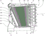
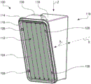
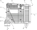
FIG. 1 is a perspective cross-sectional view of an embodiment of a filter according to the present disclosure with an inserted primary and secondary filter cartridge;
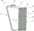
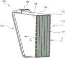
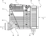
FIG. 2 is the filter of FIG. 1 without the secondary filter cartridge inserted;
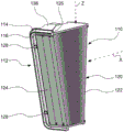
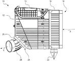
FIG. 3 is the filter of FIG. 1 without the main cartridge inserted;
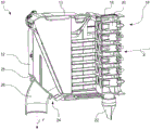
FIG. 4 is a cross-sectional view of the filter of FIG. 1;
FIG. 5 is a perspective exterior view of the filter of FIG. 1 according to the present invention;
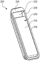
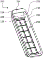
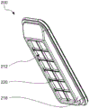
FIG. 6 is a perspective view of a secondary filter cartridge having a filter body according to the present disclosure;
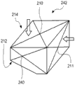
FIG. 6a is a perspective view of a filter body of an alternative secondary filter cartridge according to the present disclosure;
FIGS. 7 and 8 are perspective views of the secondary filter cartridge of FIG. 6 without the filter body;
FIG. 9 is a perspective cross-sectional view of the filter of FIG. 6;
FIG. 10 is a cross-sectional view of the filter of FIG. 7;
FIG. 11 is a perspective front view of the main filter cartridge;
FIG. 12 is a perspective rear view of the main filter cartridge of FIG. 11;
FIG. 13 is a perspective cross-sectional view of the main filter cartridge of FIG. 11;
FIG. 14 is a perspective rear view of the main cartridge of FIG. 11 without the edge protector;
fig. 15 and 16 are perspective external views of the filter of fig. 5 with different positions of the outflow nipple;
FIG. 17 is a side view of the filter of FIG. 5;
FIG. 18 is a side view of the filter of FIG. 15; and
fig. 19 is a side view of the filter of fig. 16.
Detailed Description
With reference to fig. 1 to 5, an embodiment of a filter 10 according to the present invention will now be described. Such a filter 10 can be used, for example, in an intake manifold of a construction or agricultural machine, a compressor or another device with an internal combustion engine, for filtering a fluid, in particular air. The filter 10 includes a filter housing 12 that is roughly divisible into a raw side region 14 and a clean side region 16.
The filter 100 performs flow by following the main inflow direction X. On the inflow side 16, the fluid to be filtered impinges on a roughening or preseparating module 18, which in the present case is designed as a cyclone block. In the cyclone block 18, a plurality of individual pre-separation units 20 are connected in parallel in a so-called multi-cyclone block. The dust and/or water which has been pre-separated in the cyclone block 18 is removed from the filter housing 12 via the outlet connection 22.
Downstream of the cyclone block 18, the fluid to be filtered flows into the main filter cartridge 100. The main filter cartridge 100 is in the present case realized as a prism. The inflow surface 110 of main cartridge 100 is not positioned parallel to the outflow surface 112 of main cartridge 100. Rather, the inflow surface 110 and the outflow surface 112 are angularly positioned relative to each other. In the present case, the inflow surface 110 of the main cartridge 100 is smaller than the outflow surface 112 of the main cartridge 100 with respect to the desired surface area. On the outflow side of the main cartridge 100, the sub-cartridge 200 is disposed in the filter housing 12. The main inflow surface 210 of the secondary filter element 200 is oriented towards the outflow surface 112 of the main cartridge 100 and is in particular arranged parallel to this outflow surface 112. In this embodiment, the outflow surface 212 is oriented parallel to the main inflow surface 210 of the secondary filter cartridge 200. Due to the inclined position of the outflow surface 112 of the main cartridge 100, a deflection of the main flow direction X already occurs upon inflow of fluid from the main cartridge 100, but also upon inflow from the auxiliary cartridge 200. Due to the outflow geometry of the filter housing 12 in the outflow region 24, the flowing fluid is deflected into the outflow direction Y and is guided to the outflow connection 26. In the present case, the main outflow direction Y is substantially perpendicular to the main inflow direction X. However, other outflow directions are also possible. This will be explained in more detail in connection with fig. 15 to 19, in particular.
Secondary cartridge flow-in surface 210 extends generally parallel to and spaced a distance from sealing surface 114 of primary cartridge 100. The distance is less than 2 cm; in this example, the pitch is 1 cm.
Fig. 11-14 illustrate a main filter cartridge 100. Main cartridge 100 includes an inlet surface 110 and an outlet surface 112. Inflow to the main cartridge 100 occurs along a main inflow direction X, and flow through the main cartridge 100 occurs along a main flow direction X1. Main cartridge 100 includes a cartridge frame 118 that receives a filter body 120. The filter body 120 is in the present case realized as a pleated bellows. The inflow-side flap edge 122 is positioned opposite the outflow-side flap edge 124. In fig. 11 to 14, the inflow-side flap edge 122 and the outflow-side flap edge 124 are positioned parallel, substantially perpendicular to the main flow direction X1 and substantially horizontal. This orientation of the flap edges 122, 124 enables a change in the flap depth in the direction of the insertion direction Z. Along the insertion direction Z, the main cartridge 100 may be inserted into the filter housing 12 of the filter 10. In this embodiment, the height of the folder decreases in the insertion direction Z. This causes the inflow surface 110 to tilt relative to the outflow surface 112.
In the region of the outflow surface 110, the filter frame 118 has a sealing surface 114, along which sealing surface 114 a circumferentially extending seal 116 is provided. The seal serves to separate the raw side region 14 from the clean side region 16 of the filter housing 12 of the filter 10 when the main cartridge 100 is inserted into the filter 10. The seal 112 includes a generally U-shaped cross-section.
For reinforcement and better mechanical connection of the seal 116 to the filter frame 118, a web 126 is provided which engages the U-shape of the seal 116. At the same time, seal 116 can contact or penetrate filter body 120 such that a bonded connection of filter body 120 to cartridge frame 118 and a fluid-tight sealing action between filter body 120 and cartridge frame 118 are simultaneously produced.
Furthermore, the seal 116 comprises a spacer structure, which in the present case is realized as a support knob 128. The support knob 128 is a component of the sealing material of the seal 116. As can be seen from the cross-sectional view of fig. 4, when the main cartridge 100 and the sub-cartridge 200 are inserted into the filter housing 12 of the filter 10, the support knob 128 contacts the sub-cartridge 200, particularly the sub-cartridge frame. In this state, the secondary filter cartridge 200 cannot be removed from the sealed position in the filter housing 12 even for, for example, a vibration stimulus that can be transmitted through the filter housing 12. Furthermore, by means of the support knob 128, it is ensured that the secondary filter cartridge 200 is seated in the correct position inside the filter housing 12 after installation of the main filter cartridge 100 and closure of the lid 13.
A plurality of support knobs 128 are positioned along the seal 116 on a side facing the outflow surface 112. For example, they may be manufactured integrally with the seal 116 when the seal 116 is manufactured.
The seal 116 is located at the outflow surface 112 of the main cartridge 100 and acts in a direction perpendicular to the outflow surface 112, i.e. substantially axially along the main flow direction X1.
The main cartridge 100 includes an edge protector 130 at its inflow side 110, the edge protector 130 extending circumferentially around the exterior of the filter frame 118. The edge protector 130 is designed such that impacts to the filter frame 118 can be absorbed and at least partially compensated for when the main cartridge 100 is knocked, for example when cleaning is performed. In this manner, breakage of the filter frame 118 or other damage to the filter cartridge 100 (e.g., the filter body 120) can be avoided. The edge protector 130 extends circumferentially around the inflow side edge of the filter element 100. In this context, a separate interruption, for example a notch 134, can be provided. The notch 134 is created when the edge protector 130 is manufactured. Herein, the filter frame 118 is positioned in a mold with the filter body 120. The webs fix the spacing between the mold bottom and the filter body 118 and cause the formation of the notch 134 during the casting process.
The cutout 136 is provided at the inflow side edge 132. The cutout 136 penetrates a side wall of the filter frame 118 and thus extends perpendicularly to the main flow direction X1. During the casting process already mentioned, the casting material for the edge protector 130 penetrates the cut 136, contacts the inner wall of the cartridge frame 118, and in particular the filter body 120. In this manner, a fluid-tight seal between filter body 120 and cartridge frame 118 and an adhesive bond between these two components are simultaneously created. Thus, the edge protector 130 is integrally manufactured with the adhesive connection between the filter body 120 and the cartridge frame 118 and the sealing action still required between these two components. For example, the edge protector 130 may be made of foamable polyurethane. However, silicone-based material systems are also possible.
The filter cartridge 100 includes a handle 138. The handle 138 interacts with the cover 13 of the filter 10 and ensures that the main cartridge 100 is reliably seated in the filter housing 12 and at the same time exerts an axially directed pressure on the seal 116 in the main flow direction X1 and in this way ensures a fixed sealing position of the main cartridge 100 in the filter housing 12.
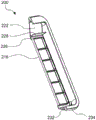
Fig. 6-10 illustrate an embodiment of a secondary filter cartridge 200. The secondary filter cartridge 200 includes a main flow-in surface 210, a flow-out surface 212, and a main flow direction Y1. In addition, the secondary filter cartridge 200 includes a filter body 214 supported by a cartridge frame 216. On the inflow side, a cartridge frame 216 having a frame area 218 that circumferentially surrounds the filter body 214 is substantially flush with the filter body. In the inserted state of the two filter cartridges 100, 200, the frame area 218 can serve as a seat for the support knob 128 of the main filter cartridge 100, for example.
In the present embodiment, the filter body 214 is generally a parallelepiped. However, other basic shapes are also possible, such as prisms. On the outflow side, i.e. in the region of the outflow surface 212, the cartridge frame 216 is provided with a grid structure 220. The grating structure 220 at least partially covers the outflow surface 212. In the case of a higher pressure difference between the inflow side 210 and the outflow side 212, the lattice structure 220 prevents an undesired bending or even a falling out of the filter body 214.
At the narrow side of the parallelepiped filter body 214, the cartridge frame 216 is provided with a handle recess 222. In order to provide a comfortable grip in the handle recess 222 for the hand of a person desiring to replace the secondary filter cartridge 200, the frame area 218 in the area of the handle recess 222 is widened to the handle stay 224. The width of the handle struts 224 is selected such that in this case a direct inflow of fluid flowing out of the main cartridge outflow side 112 towards the filter body 214 is possible, in particular on the side facing the handle recess 222. This is also readily apparent in the sectional view of fig. 4, in particular. Likewise, from the uppermost edge 113 of the primary filter element flow-out surface 112, the exiting fluid is able to flow directly to the filter body 214 of the secondary filter cartridge 200. In this case, in particular, fluid can enter the filter body 214 through the auxiliary inflow surface 211.
In this embodiment, the filter body 214 is designed as a filter bellows. The fold edge in this case extends parallel to the longitudinal axis of the secondary filter cartridge 200, so that the end face of the fold forms an auxiliary inflow surface 211. The fold edges of the folds form a main inflow surface 210 and an outflow surface 212. By combining the handle recess 222 and the filter bellows 214 with a lateral inflow via the auxiliary inflow surface 211, the pressure loss at the secondary filter cartridge 200 can be reduced, since the secondary filter cartridge 200 matches the flow guidance from the main filter cartridge 100 to the outflow connection in the filter housing 12 significantly better. At the same time, the grid structure 220 at the outflow side 212 increases the collapse resistance of the secondary filter cartridge 200. In addition, filter cartridge 200 may be easily removed with the aid of an integral handle at handle recess 222.
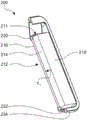
The secondary filter cartridge 200 includes a filter frame 216 that provides a groove 226 that extends circumferentially around the outflow side edge of the filter body 214. Also, a web 228 is provided on the side of cartridge frame 216 facing handle recess 222. The groove 226 serves as a molding for the circumferentially extending adhesive connection and sealing action of the filter body 214 with the cartridge frame 216. The sealing action and the adhesive connection are realized by a sealing material 230 (see fig. 9). For example, the sealing material 230 may be foamed polyurethane. However, silicone-based material systems are also possible.
The groove 226 and the additional web 228 ensure a good mechanical coupling of the sealing material 230 on the cartridge frame 216. Furthermore, this configuration has the advantage that no further processing steps, such as cutting the sealing material 230 to the required size, are required after introduction of the sealing material 230 into the groove 226 and insertion of the filter body 214 into the cartridge frame 216 and subsequent foaming and hardening. Excess material can be partially absorbed by the filter body 214 or can reach an intermediate area between the filter body 214 and the cartridge frame 216 without being detrimental.
The depth of the groove 226 extends generally along the main flow direction Y1 of the secondary filter cartridge 200. The outlet side grill structure 222 can be integrally formed with the cartridge frame 216.
At the inflow side perimeter of cartridge frame 216, cartridge frame 216 has a seal receiving groove 232. In the seal receiving groove 232, a seal 234 made of, for example, porous rubber can be inserted. The seal 234 thus acts radially, i.e. perpendicularly to the main flow direction Y1 of the secondary filter cartridge 200.
Fig. 15 to 19 show a filter 10 with differently oriented outlet connection 26. The filter housing 12 of the filter 10 comprises a fastening area 25 in the outflow area 24. The fastening region 25 is positioned at an angle of approximately 45 ° with respect to the main inflow direction X of the filter housing 12. The outflow nipple 26 can be attached to the fastening area 25. The outflow nipple 26 is shaped such that the fluid passing through the flow outflow nipple 26 undergoes a 45 ° deflection. The outflow nipple 46 is rotatably attached before final attachment on the fastening surface 25. Thus, at a very late point in time of the manufacture of the filter 10, the final deflection direction or outflow direction Y of the filter 10 can then be defined. In the geometry shown in this embodiment, collinear flow (fig. 15, 18), 90 ° deflection (fig. 17), and a range of intermediate angles are possible. In the angular range between the extreme angles, additional lateral deflection occurs.
Claims (43)
1. A secondary filter cartridge (200) for a filter (10) for filtering a fluid, wherein the secondary filter cartridge (200) is designed to be inserted into a filter (10) downstream of a primary filter cartridge (100) and comprises a primary inflow surface (210), an outflow surface (212) and a primary flow direction (Y1), a filter body (214) through which a flow can pass along the primary flow direction (Y1), a cartridge frame (216) supporting the filter body (214), wherein the cartridge frame (216) comprises a seal (234) for separating a filter interior of the filter (10) into a clean side and an uncleaned side and an adhesive connection (230) between the filter body (214) and the cartridge frame (216);
wherein the cartridge frame (216) comprises a handle region (222) on the inflow side, which is realized as a handle recess and which is directed towards the filter body (214);
wherein an auxiliary inflow surface (211) is provided laterally of the main inflow surface (210).
2. The secondary filter cartridge of claim 1, wherein the fluid is air.
3. The secondary filter cartridge of claim 1, wherein the filter is for an internal combustion engine.
4. The secondary filter cartridge of claim 1, wherein the seal (234) is designed to act radially with respect to the main flow direction (Y1).
5. The secondary filter cartridge of claim 1, wherein the seal (234) is designed to extend circumferentially around the filter cartridge (200) perpendicular to the main flow direction (Y1).
6. The secondary filter cartridge of any of claims 1-5, wherein a support section of the cartridge frame (216) extends circumferentially around the filter body (214) and includes an inner edge on an inner side.
7. The secondary filter cartridge of claim 6, wherein the cartridge frame (216) includes a groove (226), the groove (226) for receiving an adhesive material (230) of an adhesive connection.
8. The secondary filter cartridge of claim 7, wherein the depth of the groove (226) extends in the direction of the main flow direction (Y1).
9. The secondary filter cartridge of any of claims 1-5, wherein the seal-receiving section (232) of the cartridge frame (216) circumferentially surrounds an exterior of the filter body (214).
10. The secondary filter cartridge of any of claims 1-5, wherein the adhesive connection (230) comprises polyurethane.
11. The secondary filter cartridge of claim 10, wherein the adhesive connection (230) comprises foamed polyurethane.
12. The secondary filter cartridge of any of claims 1-5, wherein the adhesive connection (230) partially penetrates the filter body (214).
13. The secondary filter cartridge of any of claims 1-5, wherein the seal (234) comprises a porous rubber.
14. The secondary filter cartridge of any of claims 1-5, wherein the cartridge frame (216) includes a grate (220) covering the outflow surface (212) on an outflow side.
15. The secondary filter cartridge of claim 14, wherein the grate (220) is integral with the cartridge frame (216).
16. A secondary filter cartridge for a filter (10) for filtering a fluid, comprising a main inflow surface (210), an outflow surface (212) and a main flow direction (Y1), a filter body (214) through which a flow can be passed along the main flow direction (Y1), a cartridge frame (216) supporting the filter body (214), wherein the cartridge frame (216) comprises a seal (234) for separating the filter interior of the filter (10) into a cleaned side and an uncleaned side, and the cartridge frame (216) comprises a handle area (222) at the inflow side, wherein the handle area (222) is designed such that an inflow to the filter body (214) via the handle area (222) and a manual removal of the secondary filter cartridge (200) are possible;
wherein the handle region (222) is realized as a handle recess and the handle recess is directed towards the filter body (214);
wherein an auxiliary inflow surface (211) is provided laterally of the main inflow surface (210).
17. The secondary filter cartridge of claim 16, wherein the fluid is air.
18. A secondary filter cartridge according to claim 16, wherein the filter is for an internal combustion engine.
19. The secondary filter cartridge of claim 16, wherein the handle area (222) enables inflow into the filter body (214) laterally adjacent to the primary inflow surface (210).
20. The secondary filter cartridge of claim 16, wherein the handle area (222) does not protrude beyond the primary flow-in surface (210) in a primary flow direction (Y1).
21. The secondary filter cartridge of claim 16, wherein the filter body (214) is a parallelepiped.
22. The secondary filter cartridge of claim 16, wherein the filter body (214) is realized as a filter bellows.
23. The secondary filter cartridge of claim 22, wherein an end face of the filter bellows points in the direction of the handle region (222).
24. The secondary filter cartridge of claim 16, wherein the cartridge frame (216) includes a grate (220) covering the outflow surface (212) on an outflow side.
25. The secondary filter cartridge of claim 24, wherein the grate (220) is integral with the cartridge frame (216).
26. A filter (10) for filtering a fluid, comprising a filter housing (12) comprising a raw side region (14) and a clean side region (15), a main filter cartridge (100) and a secondary filter cartridge (200) according to any one of claims 1-25, wherein the main filter cartridge (100) is insertable into the filter housing (12) and comprises a main cartridge inflow surface (110), a main cartridge flow direction (X1), a main cartridge outflow surface (112) and a seal (116) arranged on a sealing surface (114) for fluid-tight separation of the filter housing (12) into the raw side region (14) and the clean side region (15), and the secondary filter cartridge (200) is arranged downstream of the main filter cartridge (100), the secondary filter cartridge (200) comprising a main inflow surface (210) of the secondary filter cartridge, a secondary filter cartridge (210), and a secondary filter cartridge (200) comprising a primary filter cartridge inflow surface (110), A secondary cartridge flow direction (Y1) and a secondary cartridge outflow surface (212), wherein the sealing surface (114) is arranged inclined with respect to the main cartridge flow direction (X1) of the main cartridge (100).
27. The filter according to claim 26 wherein the fluid is air.
28. The filter of claim 26, wherein the filter is used in an internal combustion engine.
29. The filter of claim 26, wherein the sealing surface (114) and the main cartridge flow direction (X1) are positioned at an angle relative to each other, the angle being between 80 ° and 10 °.
30. The filter of claim 26, wherein the sealing surface (114) and the main cartridge flow-out surface (112) extend in parallel.
31. The filter of claim 30, wherein the sealing surface (114) and the main cartridge flow-out surface (112) are positioned in a plane.
32. A filter according to any one of claims 26-31, wherein the main inflow surface (210) of the secondary cartridge extends parallel to the sealing surface (114) and at a distance apart.
33. The filter according to claim 32 wherein the spacing is less than 2 cm.
34. The filter according to claim 33 wherein the spacing is 1 cm.
35. A filter according to any one of claims 26-31, wherein the basic shape of the secondary filter cartridge (200) is a parallelepiped.
36. A filter according to any one of claims 26-31, wherein the basic shape of the main cartridge (100) is a prism having a quadrilateral shape as a base surface and as a top surface.
37. A filter according to any one of claims 26-31, wherein the main cartridge (100) is a pleated bellows with at least two different pleat depths.
38. Filter according to any one of claims 26-31, wherein the filter housing (12) comprises an inflow direction (X), an outflow direction (Y) and an outflow region (24) with an outflow opening, and an outflow nipple (26) is fastenable to the outflow region (24), wherein the outflow region (24) comprises a fastening surface (25) for the outflow nipple (26), and the fastening surface is positioned at an angle of 45 ° with respect to the main cartridge flow direction (X1).
39. A filter according to claim 38, wherein the outflow nipple (26) is shaped so as to cause a deflection of the flow direction by 45 °.
40. Filter according to claim 38, wherein the outflow nipple (26) comprises a fastening area realized in rotational symmetry for attachment on the filter housing (12).
41. A filter as claimed in claim 38, wherein the outflow direction (Y) and the fastening surface (25) are positioned at an angle of 45 ° with respect to each other.
42. The filter according to claim 38, wherein the fastening surface (20) and the secondary cartridge flow-out surface (212) extend in parallel.
43. A filter according to any one of claims 26-31, wherein the main cartridge (100) is insertable into and removable from the filter housing (12) along an insertion axis (Z) positioned at an angle relative to a main flow direction (X1) between 90 ° and the angle at which the sealing surface (114) is positioned relative to the main flow direction (X1), the filter housing (12) comprising a cover designed such that, in its state of closing the filter housing (12), it exerts a force on the main cartridge (100) in the direction of the sealing surface (114).
Applications Claiming Priority (7)
| Application Number | Priority Date | Filing Date | Title |
|---|---|---|---|
| DE202014004894.0U DE202014004894U1 (en) | 2014-06-18 | 2014-06-18 | Filter element with prismatic basic shape |
| DE202014004894.0 | 2014-06-18 | ||
| DE202014004897.5 | 2014-06-18 | ||
| DE202014004897.5U DE202014004897U1 (en) | 2014-06-18 | 2014-06-18 | Filter with variable outflow direction |
| DE202014008899 | 2014-11-11 | ||
| DE202014008899.3 | 2014-11-11 | ||
| PCT/EP2015/063592 WO2015193372A2 (en) | 2014-06-18 | 2015-06-17 | Filter and filter cartridge |
Publications (2)
| Publication Number | Publication Date |
|---|---|
| CN106457109A CN106457109A (en) | 2017-02-22 |
| CN106457109B true CN106457109B (en) | 2020-12-01 |
Family
ID=53404567
Family Applications (3)
| Application Number | Title | Priority Date | Filing Date |
|---|---|---|---|
| CN201580032480.2A Active CN106973567B (en) | 2014-06-18 | 2015-06-17 | Filter and filter cartridge |
| CN201580032511.4A Active CN106457109B (en) | 2014-06-18 | 2015-06-17 | Filter and filter cartridge |
| CN201580032483.6A Active CN106457108B (en) | 2014-06-18 | 2015-06-17 | Filter and filter cartridge |
Family Applications Before (1)
| Application Number | Title | Priority Date | Filing Date |
|---|---|---|---|
| CN201580032480.2A Active CN106973567B (en) | 2014-06-18 | 2015-06-17 | Filter and filter cartridge |
Family Applications After (1)
| Application Number | Title | Priority Date | Filing Date |
|---|---|---|---|
| CN201580032483.6A Active CN106457108B (en) | 2014-06-18 | 2015-06-17 | Filter and filter cartridge |
Country Status (8)
| Country | Link |
|---|---|
| US (7) | US20170096972A1 (en) |
| EP (6) | EP3157653B1 (en) |
| CN (3) | CN106973567B (en) |
| BR (2) | BR112016027956B1 (en) |
| DE (4) | DE112015002900A5 (en) |
| ES (2) | ES2919662T3 (en) |
| PL (2) | PL3738660T3 (en) |
| WO (3) | WO2015193346A2 (en) |
Families Citing this family (31)
| Publication number | Priority date | Publication date | Assignee | Title |
|---|---|---|---|---|
| US11235274B2 (en) | 2011-06-30 | 2022-02-01 | Donaldson Company, Inc. | Filter systems; components; features; and, methods of assembly and use |
| EP3157653B1 (en) * | 2014-06-18 | 2020-06-03 | Mann+Hummel GmbH | Filter and filter cartridge |
| DE102016003454A1 (en) * | 2015-04-10 | 2016-10-13 | Mann + Hummel Gmbh | Filter holder and filter assembly |
| DE102016003455B4 (en) * | 2015-04-10 | 2020-08-06 | Mann+Hummel Gmbh | Filter holder and filter arrangement |
| DE102016003456A1 (en) * | 2015-04-10 | 2016-10-13 | Mann + Hummel Gmbh | Filter holder, filter element and filter assembly |
| JP6434924B2 (en) * | 2016-01-25 | 2018-12-05 | 本田技研工業株式会社 | Air cleaner |
| DE102016001134A1 (en) * | 2016-02-03 | 2017-08-03 | Mann + Hummel Gmbh | Filter housing and filter |
| DE102016001133A1 (en) * | 2016-02-03 | 2017-08-03 | Mann + Hummel Gmbh | Filter element, element frame of a filter element, filter bellows of a filter element and filter |
| USD805106S1 (en) * | 2016-04-22 | 2017-12-12 | Centrifugal Universal Filtration Technology (Pty) Ltd | Pre-cleaner insert for vehicle snorkel |
| GB2550356B (en) * | 2016-05-16 | 2021-11-17 | Bitfury Group Ltd | Filter for immersion cooling apparatus |
| WO2017218966A1 (en) | 2016-06-17 | 2017-12-21 | Donaldson Company, Inc. | Air cleaner assemblies and cartridge |
| DE102016012328B4 (en) * | 2016-10-17 | 2019-07-04 | Mann+Hummel Gmbh | Filter device with a round filter element, in particular for gas filtration |
| CN109890666B (en) | 2016-10-20 | 2022-03-11 | 康明斯滤清系统知识产权公司 | Discontinuous directional protrusions of flat sheet |
| DE102016013844A1 (en) * | 2016-11-22 | 2018-05-24 | Mann + Hummel Gmbh | Round filter element with elongated cross-sectional shape |
| DE102017005958B3 (en) * | 2017-04-06 | 2018-10-11 | Mann+Hummel Gmbh | filtering device |
| BR112019025694A2 (en) * | 2017-06-05 | 2020-09-01 | Donaldson Company, Inc. | air purifier assemblies and methods of use |
| WO2019011724A1 (en) * | 2017-07-14 | 2019-01-17 | Haldor Topsøe A/S | Particle separating catalytic chemical reactor with filter unit |
| CN111432909B (en) * | 2017-08-10 | 2022-07-01 | 唐纳森公司 | Fluid filtration apparatus, systems and methods |
| CN111465442B (en) | 2017-09-25 | 2022-10-11 | 唐纳森公司 | Filter assembly |
| US20210046413A1 (en) * | 2018-05-07 | 2021-02-18 | Cummins Filtration Ip, Inc. | High performance density element with angle between inlet flow and outlet flow |
| US20200072169A1 (en) * | 2018-08-28 | 2020-03-05 | Parker-Hannifin Corporation | Non-cylindrical filter element and side entry air cleaner incorporating the same |
| CN112007451B (en) * | 2019-05-31 | 2024-03-29 | 大金工业株式会社 | Air purifying device |
| JP2022519925A (en) | 2019-03-27 | 2022-03-25 | ドナルドソン カンパニー,インコーポレイティド | Particle separator filter with an axially extending flow surface |
| US11395984B2 (en) * | 2019-05-24 | 2022-07-26 | Flory Industries | Dust control system and related methods |
| DE102019115568A1 (en) * | 2019-06-07 | 2020-12-10 | Mann+Hummel Gmbh | Filter element and filter system |
| CN110755957B (en) * | 2019-11-02 | 2020-11-10 | 山东国晟环境科技有限公司 | Purifying tower anti-blocking pipeline with rapid compensation filtering component |
| DE102020200945A1 (en) * | 2020-01-27 | 2021-07-29 | Deere & Company | Air filter system for a commercial vehicle |
| JP7318575B2 (en) * | 2020-03-17 | 2023-08-01 | コベルコ建機株式会社 | construction machinery |
| CN112090185A (en) * | 2020-08-25 | 2020-12-18 | 深圳市英威腾交通技术有限公司 | Ventilation dust filter |
| US11358088B1 (en) | 2021-04-22 | 2022-06-14 | Mann+Hummel Gmbh | Filter assembly for an air filter |
| EP4326420A1 (en) * | 2021-06-14 | 2024-02-28 | Baldwin Filters, Inc. | Filter cartridge including u-shaped canted inlet frame; filter system including same |
Citations (2)
| Publication number | Priority date | Publication date | Assignee | Title |
|---|---|---|---|---|
| WO2010114906A1 (en) * | 2009-03-31 | 2010-10-07 | Donaldson Company, Inc. | Air cleaner, components thereof, and methods |
| CN102015062A (en) * | 2008-02-26 | 2011-04-13 | 曼·胡默尔有限公司 | Air filter comprising a security element |
Family Cites Families (46)
| Publication number | Priority date | Publication date | Assignee | Title |
|---|---|---|---|---|
| DE2725437A1 (en) | 1977-06-04 | 1978-12-21 | Heinz Hoelter | Folded filter element - with radial instead of axial profile for easier flange connections |
| DE7835720U1 (en) | 1978-11-30 | 1979-03-29 | Delbag-Luftfilter Gmbh, 1000 Berlin | POCKET AIR FILTER FOR AIR CLEANING |
| IN152016B (en) * | 1980-11-24 | 1983-09-24 | Klenzaids Engineers Plc | |
| DE8808632U1 (en) * | 1988-07-06 | 1988-09-01 | Ing. Walter Hengst Gmbh & Co Kg, 4400 Muenster, De | |
| DE4031160C1 (en) * | 1990-10-03 | 1992-05-14 | Fa. Andreas Stihl, 7050 Waiblingen, De | |
| DE4407124B4 (en) * | 1994-03-04 | 2018-10-31 | Fa. Andreas Stihl | Air filter for an internal combustion engine |
| US5795361A (en) * | 1996-03-12 | 1998-08-18 | Dana Corporation | Filter configuration |
| IN189834B (en) * | 1997-04-18 | 2003-04-26 | Mann & Hummel Filter | |
| US5853445A (en) * | 1997-08-06 | 1998-12-29 | Dana Corporation | Interlocking dual filter |
| JPH11267433A (en) * | 1998-03-24 | 1999-10-05 | Sanden Corp | Filter device |
| US6179890B1 (en) * | 1999-02-26 | 2001-01-30 | Donaldson Company, Inc. | Air cleaner having sealing arrangement between media arrangement and housing |
| DE19930614A1 (en) * | 1999-07-02 | 2001-01-04 | Mann & Hummel Filter | Filter insert |
| US6200465B1 (en) * | 1999-08-06 | 2001-03-13 | Dana Corporation | Filter with integral lift tab |
| US6348077B1 (en) * | 1999-11-19 | 2002-02-19 | Solberg Manufacturing, Inc. | Multiple stage air-intake filter apparatus |
| US6780534B2 (en) * | 2001-04-11 | 2004-08-24 | Donaldson Company, Inc. | Filter assembly for intake air of fuel cell |
| KR20050098922A (en) | 2003-02-11 | 2005-10-12 | 도널드선 컴파니 인코포레이티드 | Air cleaner arrangements; serviceable filter elements;and,method |
| DE102004005904B4 (en) | 2004-02-05 | 2008-07-31 | Carl Freudenberg Kg | Tubular folded filter |
| DE102004059279B4 (en) * | 2004-12-09 | 2018-05-03 | Mann + Hummel Gmbh | air filter |
| JP5053099B2 (en) * | 2005-01-13 | 2012-10-17 | ドナルドソン カンパニー,インコーポレイティド | Air filter device |
| DE102005031058A1 (en) * | 2005-07-02 | 2007-01-04 | Mahle International Gmbh | Filter element and a filter housing suitable for receiving it |
| DE102005035591A1 (en) * | 2005-07-29 | 2007-02-15 | Robert Bosch Gmbh | Filter unit, especially for exhaust gas system of internal combustion engine, has gas-permeable wall of filter bag unevenly formed for stiffening, where wall of filter bag has periodic structure |
| KR101575553B1 (en) * | 2005-10-11 | 2015-12-07 | 도날드슨 컴파니, 인코포레이티드 | Air filter arrangement, assembly, and methods |
| DE202006007073U1 (en) * | 2006-05-02 | 2007-09-13 | Dolmar Gmbh | power tool |
| DE102006028161A1 (en) * | 2006-06-16 | 2007-12-27 | Mann + Hummel Gmbh | Compact filter element with knock-out protection |
| DE102006036498A1 (en) | 2006-07-28 | 2008-02-07 | Fraunhofer-Gesellschaft zur Förderung der angewandten Forschung e.V. | Composite honeycomb structure, e.g. useful as a filter or catalytic converter, comprises comprises prismatic segments whose sides are bonded together over their whole length parallel to the direction of flow |
| EP2134444B1 (en) * | 2007-02-26 | 2018-06-20 | Donaldson Company, Inc. | Air filter cartridge |
| WO2009106590A1 (en) * | 2008-02-26 | 2009-09-03 | Mann+Hummel Gmbh | Sealing configuration |
| EP2106836A1 (en) * | 2008-03-27 | 2009-10-07 | OFFICINE METALLURGICHE G. CORNAGLIA S.p.A. | Filter cartrige, filter housing and filter assembly |
| US7972402B2 (en) * | 2008-07-17 | 2011-07-05 | Mann + Hummel Gmbh | Reinforced filter element |
| US20110233133A1 (en) | 2008-07-31 | 2011-09-29 | Cummins Filtration Ip, Inc. | Direct Flow Filter Including an Integrated Flexible Seal |
| US10293296B2 (en) * | 2008-08-15 | 2019-05-21 | MANN+HUMMEL Filtration Technology Group Inc. | Filter |
| US8404115B2 (en) * | 2009-07-20 | 2013-03-26 | Cummins Filtration Ip Inc. | Sealed filter element |
| DE102009060214A1 (en) * | 2009-12-23 | 2011-06-30 | MAHLE International GmbH, 70376 | Filter element and manufacturing process |
| WO2011115973A2 (en) * | 2010-03-17 | 2011-09-22 | Baldwin Filters, Inc. | Fluid filter |
| US8852310B2 (en) * | 2010-09-07 | 2014-10-07 | Cummins Filtration Ip Inc. | Filter and filter media having reduced restriction |
| JP5922333B2 (en) * | 2011-03-02 | 2016-05-24 | 本田技研工業株式会社 | Air cleaner structure for small vehicles |
| DE102012000470A1 (en) * | 2012-01-13 | 2013-07-18 | Mann + Hummel Gmbh | Air filter element and air filter |
| US9504947B2 (en) * | 2012-11-13 | 2016-11-29 | Cummins Filtration Ip, Inc. | Air filter assemblies and carrier frames having vortex-generating flow guide |
| JP6377142B2 (en) * | 2013-05-22 | 2018-08-22 | ドナルドソン カンパニー,インコーポレイティド | Filter element and air cleaner |
| DE102014009887A1 (en) * | 2013-07-12 | 2015-01-15 | Mann + Hummel Gmbh | Filter element, filter with a filter element and filter housing of a filter |
| DE102014009026A1 (en) * | 2013-07-12 | 2015-01-15 | Mann + Hummel Gmbh | Filter element with at least one guide web, filter with a filter element and filter housing of a filter |
| DE102014017483A1 (en) * | 2013-12-12 | 2015-06-18 | Mann + Hummel Gmbh | Filter housing and filter assembly |
| EP3157653B1 (en) * | 2014-06-18 | 2020-06-03 | Mann+Hummel GmbH | Filter and filter cartridge |
| US20160059172A1 (en) * | 2014-08-28 | 2016-03-03 | Caterpillar Inc. | Filter element and air cleaner assembly |
| DE102014016300B4 (en) * | 2014-11-06 | 2018-05-30 | Mann + Hummel Gmbh | Filter and use of a hollow filter element in this filter |
| DE102014016301A1 (en) * | 2014-11-06 | 2016-05-25 | Mann + Hummel Gmbh | Hollow filter element of a filter for filtering fluid, filter, filter housing and sealing a hollow filter element |
-
2015
- 2015-06-17 EP EP15729838.1A patent/EP3157653B1/en active Active
- 2015-06-17 BR BR112016027956-5A patent/BR112016027956B1/en active IP Right Grant
- 2015-06-17 EP EP20176320.8A patent/EP3738660B1/en active Active
- 2015-06-17 WO PCT/EP2015/063542 patent/WO2015193346A2/en active Application Filing
- 2015-06-17 DE DE112015002900.1T patent/DE112015002900A5/en active Pending
- 2015-06-17 ES ES20176320T patent/ES2919662T3/en active Active
- 2015-06-17 DE DE102015007659.0A patent/DE102015007659A1/en active Pending
- 2015-06-17 CN CN201580032480.2A patent/CN106973567B/en active Active
- 2015-06-17 EP EP15729473.7A patent/EP3157652B1/en active Active
- 2015-06-17 PL PL20176320.8T patent/PL3738660T3/en unknown
- 2015-06-17 WO PCT/EP2015/063537 patent/WO2015193341A2/en active Application Filing
- 2015-06-17 CN CN201580032511.4A patent/CN106457109B/en active Active
- 2015-06-17 ES ES15729838T patent/ES2806461T3/en active Active
- 2015-06-17 CN CN201580032483.6A patent/CN106457108B/en active Active
- 2015-06-17 EP EP20178347.9A patent/EP3721967B1/en active Active
- 2015-06-17 EP EP20169881.8A patent/EP3741443B1/en active Active
- 2015-06-17 PL PL20178347.9T patent/PL3721967T3/en unknown
- 2015-06-17 WO PCT/EP2015/063592 patent/WO2015193372A2/en active Application Filing
- 2015-06-17 DE DE112015002880.3T patent/DE112015002880A5/en active Pending
- 2015-06-17 BR BR112016026996-9A patent/BR112016026996B1/en active IP Right Grant
- 2015-06-17 DE DE112015002877.3T patent/DE112015002877A5/en active Pending
- 2015-06-17 EP EP15729483.6A patent/EP3157654B1/en active Active
-
2016
- 2016-12-18 US US15/382,701 patent/US20170096972A1/en not_active Abandoned
- 2016-12-18 US US15/382,700 patent/US10337471B2/en active Active
- 2016-12-18 US US15/382,702 patent/US10337472B2/en active Active
-
2019
- 2019-05-30 US US16/427,177 patent/US10865749B2/en active Active
- 2019-06-03 US US16/429,903 patent/US10954899B2/en active Active
- 2019-06-13 US US16/439,847 patent/US10961957B2/en active Active
-
2020
- 2020-12-15 US US17/121,932 patent/US11719202B2/en active Active
Patent Citations (2)
| Publication number | Priority date | Publication date | Assignee | Title |
|---|---|---|---|---|
| CN102015062A (en) * | 2008-02-26 | 2011-04-13 | 曼·胡默尔有限公司 | Air filter comprising a security element |
| WO2010114906A1 (en) * | 2009-03-31 | 2010-10-07 | Donaldson Company, Inc. | Air cleaner, components thereof, and methods |
Also Published As
Similar Documents
| Publication | Publication Date | Title |
|---|---|---|
| CN106457109B (en) | Filter and filter cartridge | |
| US9726123B2 (en) | Air filter, filter element and filter housing of an air filter | |
| US7695539B2 (en) | Filter element and filter housing suitable for accommodation the same | |
| US10105630B2 (en) | Hollow filter element of a filter for filtering fluid, filter, filter housing, and seal of a hollow filter element | |
| US9776118B2 (en) | Filter element and housing with cooperating filter media support structures | |
| US10105629B2 (en) | Filter, hollow filter element, and filter housing of a filter, and seal of a hollow filter element | |
| WO2009064526A1 (en) | Authorized filter servicing and replacement | |
| CN110446539B (en) | Filtering sealing system | |
| BR112014017028B1 (en) | AIR FILTER AND AIR FILTER ELEMENT ARRANGEMENT | |
| AU2016259419B2 (en) | Engine Panel Filter and Housing System | |
| CN108371848B (en) | Air filter with integrated snow protection and filter element | |
| CN111615420A (en) | Filter element, in particular for gas filtration | |
| US9901857B2 (en) | Filter element, especially for gas filtration | |
| US20170182448A1 (en) | Plate-Type Filter Element for Gas Filtration | |
| EP3784364B1 (en) | Cartridge group for fuel filtration | |
| US20220176295A1 (en) | Filter element with outlet port check valve |
Legal Events
| Date | Code | Title | Description |
|---|---|---|---|
| C06 | Publication | ||
| PB01 | Publication | ||
| SE01 | Entry into force of request for substantive examination | ||
| SE01 | Entry into force of request for substantive examination | ||
| GR01 | Patent grant | ||
| GR01 | Patent grant |