EP3721778A1 - Doppelbesen mit selbsthebefunktion - Google Patents
Doppelbesen mit selbsthebefunktion Download PDFInfo
- Publication number
- EP3721778A1 EP3721778A1 EP20000024.8A EP20000024A EP3721778A1 EP 3721778 A1 EP3721778 A1 EP 3721778A1 EP 20000024 A EP20000024 A EP 20000024A EP 3721778 A1 EP3721778 A1 EP 3721778A1
- Authority
- EP
- European Patent Office
- Prior art keywords
- broom
- brooms
- suspension
- roller
- spring
- Prior art date
- Legal status (The legal status is an assumption and is not a legal conclusion. Google has not performed a legal analysis and makes no representation as to the accuracy of the status listed.)
- Granted
Links
Images


Classifications
-
- A—HUMAN NECESSITIES
- A46—BRUSHWARE
- A46B—BRUSHES
- A46B5/00—Brush bodies; Handles integral with brushware
- A46B5/0004—Additional brush head
- A46B5/0012—Brushes with two or more heads on the same end of a handle for simultaneous use, e.g. cooperating with each-other
-
- A—HUMAN NECESSITIES
- A46—BRUSHWARE
- A46B—BRUSHES
- A46B17/00—Accessories for brushes
- A46B17/02—Devices for holding brushes in use
-
- A—HUMAN NECESSITIES
- A46—BRUSHWARE
- A46B—BRUSHES
- A46B5/00—Brush bodies; Handles integral with brushware
- A46B5/002—Brush bodies; Handles integral with brushware having articulations, joints or flexible portions
- A46B5/0033—Brush bodies; Handles integral with brushware having articulations, joints or flexible portions bending or stretching or collapsing
- A46B5/0041—Mechanical joint or hinge, made up of several components
-
- A—HUMAN NECESSITIES
- A46—BRUSHWARE
- A46B—BRUSHES
- A46B2200/00—Brushes characterized by their functions, uses or applications
- A46B2200/30—Brushes for cleaning or polishing
- A46B2200/302—Broom
Definitions
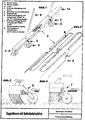
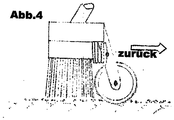
- Fig. 1 For double brooms with self-lifting function Fig. 1 , it is a broom system that rolls through Fig.1 (Photo 1) and a suspension with suspension Fig. 3 (Photo 2) is able to lift the brush body in the backward sweeping motion Fig. 4 .
- the double broom does not have to be lifted in the return movement. It rolls back over the debris, saving effort.
- the broom width (working width) can be increased significantly.
- the broom (1) was replaced with a second broom (1a) Fig. 1 , connected by means of elastic fittings (4) Fig. 2 .
- the fittings e.g. optionally fabric hoses
- Fig. 4 (Photo 4) function as a torsion joint and compensate for uneven floors. This design makes it possible to connect different brush widths and types (street brush, hall / hall brush, etc.).
- a particular advantage of the double broom is the gentle posture when sweeping. You move the broom forwards with light pressure Fig. 3 and then just pulls it back to you Fig. 4 . The broom lifts itself out and rolls back over the remaining debris. The broom does not need to be raised to reset it, as is customary in the trade. With the double broom with self-lifting function, you can create larger areas in the same time with less effort.
Landscapes
- Engineering & Computer Science (AREA)
- Mechanical Engineering (AREA)
- Cleaning Implements For Floors, Carpets, Furniture, Walls, And The Like (AREA)
Abstract
Description
-
- 1
- Besen links
- 1a
- Besen rechts
- 2
- Rolle
- 3
- Rollenaufhängung mit Feder
- 4
- Besentorsionsverbindung
- 5
- Besenstiel
- 6
- Rollenaufhängung mit gespannter Feder in der Vorwärtsbewegung
- 7
- Rollenaufhängung mit entspannter Feder in der Rückwärtsbewegung
- 8
- Elastisches/-e Formstück/-e als Torsionselement
- Beim Doppelbesen mit Selbsthebefunktion
Abb. 1 , handelt es sich um ein Besensystem, dass durch RollenAbb.1 (Foto 1) und einer Aufhängung mit FederungAbb. 3 (Foto 2) in der Lage ist, in der rückwärts Fegebewegung den Besenkörper anzuhebenAbb. 4 . - Der besondere Effekt der hier entsteht ist der, dass der Doppelbesen in der Rückholbewegung nicht angehoben werden muss. Er rollt kraftsparend über das Kehrgut zurück. Somit kann die Besenbreite (Arbeitsbreite) deutlich vergrößert werden. Hierfür wurde der Besen (1) mit einem zweiten Besen (1a)
Abb. 1 , mittels elastischer Formstücke (4) verbundenAbb. 2 . Die Formstücke (z. B. wahlweise Gewebeschläuche)Abb. 4 (Foto 4) funktionieren als Torsionsgelenk und gleichen Bodenunebenheiten aus. Durch diese Bauart ist es möglich, verschiedene Besenbreiten und -arten (Straßenbesen, Saal-/Hallenbesen usw.) zu verbinden. - Ein besonderer Vorteil des Doppelbesens ist die schonende Körperhaltung beim Fegen. Man bewegt den Besen durch leichten Druck nach vorn
Abb. 3 und zieht ihn dann einfach zu sich zurückAbb. 4 . Der Besen hebt sich hierbei selbständig aus und rollt über das noch liegende Kehrgut zurück. Der Besen braucht nicht wie handelsübliche zum Zurücksetzen angehoben werden. Mit dem Doppelbesen mit Selbsthebefunktion schafft man in der gleichen Zeit größere Flächen bei geringerem Kraftaufwand.
Claims (2)
- Bekannte Besen (Straßen-, Hallenbesen) bestehen aus einem Besenkörper mit Borsten aus verschiedenen Materialien und einem Stiel. Die Nutzung, sprich das Fegen, bedarf einer Wiederholung von vor- und rückwärtsläufigen Bewegungen. Bei diesen bekannten Besen muss der Besen in der rückläufigen Bewegung angehoben werden.
Bei der Besenselbsthebevorrichtung handelt es sich um eine Aufhängung mit Rolle und Feder; die an einem Besenkörper montiert ist. Diese Aufhängung ist so konstruiert, dass sie im Ruhezustand am Besen anliegt. Von diesen Aufhängungen werden je nach Besenbreite unterschiedlich viele verbaut. Die Aufhängung mit Rolle ist länger als die nach unten stehenden Borsten. Bei Druckbelastung, das heißt in der Vorwärtsbewegung, wird die Feder gespannt. Die Aufhängung mit Rolle schwängt vom Besen weg. Durch die Lageveränderung, der Aufhängung mit Rolle, zum Besen, senkt sich dieser ab.
In der rückläufigen Bewegung entspannt sich die Feder und zieht dadurch die Aufhängung mit Rolle zum Besen zurück. Der Längenunterschied zwischen der Aufhängung mit Rolle und Borsten ermöglicht den richtungsbezogenen Kontaktwechsel von Besen und Boden.
Die Größe und Beschaffenheit der zur Verwendung kommenden Rollen ist von der Art und Größe des Besens abhängig und nach dem Einsatz im Innen- oder Außenbereich.
Die zur Verwendung kommenden Federn sind Zug-, Druck- oder Drehfedern. Die Auswahl der Federart und der -stärke ist vom Besentyp abhängig, durch unterschiedlich zu hebende Gewichte. - Die Aufgabe der Besentorsionsverbindung besteht darin, zwei oder mehrere Besenkörper (z. B. Straßen- oder Hofbesen) stabil miteinander zu verbinden. Die so verbundenen Besen können sich in der Längsachse verdrehen.
Die Besentorsionsverbindung wurde so konzipiert, dass zwei oder mehrere Besenkörper (z. B. Straßen oder Hofbesen) stabil miteinander verbunden werden. Die so verbundenen Besen können sich in der Längsachse verdrehen.
Durch Verwendung zweier in der Längsachse, hintereinander montierter elastischer Formstücke als Verbindung zwischen den Besen, bleiben diese aber in der Fegerichtung starr.
Die Besenkörper können so Bodenunebenheiten ausgleichen und die Arbeitsbreite der miteinander verbundenen Besen bleibt beständig. Sie können nicht nach vorn oder zurück zusammenklappen.
Die Art und Größe der Verbindung, d. h. die zur Verwendung kommenden Materialien, sind abhängig von der Größe des Besens und dessen Einsatzgebietes im Innen- und Außenbereich.
Applications Claiming Priority (1)
| Application Number | Priority Date | Filing Date | Title |
|---|---|---|---|
| DE102019000778.6A DE102019000778B4 (de) | 2019-01-29 | 2019-01-29 | Doppelbesen mit Selbsthebefunktion |
Publications (3)
| Publication Number | Publication Date |
|---|---|
| EP3721778A1 true EP3721778A1 (de) | 2020-10-14 |
| EP3721778C0 EP3721778C0 (de) | 2024-10-16 |
| EP3721778B1 EP3721778B1 (de) | 2024-10-16 |
Family
ID=69176958
Family Applications (1)
| Application Number | Title | Priority Date | Filing Date |
|---|---|---|---|
| EP20000024.8A Active EP3721778B1 (de) | 2019-01-29 | 2020-01-16 | Doppelbesen mit selbsthebefunktion |
Country Status (3)
| Country | Link |
|---|---|
| EP (1) | EP3721778B1 (de) |
| DE (1) | DE102019000778B4 (de) |
| PL (1) | PL3721778T3 (de) |
Families Citing this family (1)
| Publication number | Priority date | Publication date | Assignee | Title |
|---|---|---|---|---|
| USD1085607S1 (en) * | 2023-06-14 | 2025-07-22 | Dotti Home Inc. | Broom |
Citations (3)
| Publication number | Priority date | Publication date | Assignee | Title |
|---|---|---|---|---|
| US2890470A (en) * | 1957-10-07 | 1959-06-16 | Lawrence W Schaefer | Push-type floor mop |
| US4358123A (en) * | 1978-05-16 | 1982-11-09 | Richards Dean E | Attachment for a ground traversing device and/or a ground traversing device |
| US5198036A (en) * | 1987-09-14 | 1993-03-30 | Sotolongo Enrique I | Lifting wheeled arrangement for rollers |
Family Cites Families (7)
| Publication number | Priority date | Publication date | Assignee | Title |
|---|---|---|---|---|
| US1525617A (en) * | 1923-04-16 | 1925-02-10 | Edward J Mills | Device for facilitating operation of push brushes and brooms |
| US2860360A (en) * | 1955-09-21 | 1958-11-18 | Francis M Leavelle | Sweeping mop |
| US4554699A (en) * | 1984-03-26 | 1985-11-26 | Simmons Stanley J | Flexible brush |
| SE504242C2 (sv) * | 1996-01-31 | 1996-12-16 | Carpeting I Stockholm Ab | Anordning för sammankoppling av två golvmoppstativ |
| US6694561B1 (en) * | 1998-04-06 | 2004-02-24 | Bruce Harrison | Sweeping device |
| US7000281B1 (en) * | 2004-02-17 | 2006-02-21 | Worldwide Integrated Resources, Inc. | Push broom which is convertible to a handheld whisk broom |
| WO2015104708A1 (en) * | 2014-01-07 | 2015-07-16 | Hevlin Yiftach | Device with expandable cleaning head |
-
2019
- 2019-01-29 DE DE102019000778.6A patent/DE102019000778B4/de active Active
-
2020
- 2020-01-16 PL PL20000024.8T patent/PL3721778T3/pl unknown
- 2020-01-16 EP EP20000024.8A patent/EP3721778B1/de active Active
Patent Citations (3)
| Publication number | Priority date | Publication date | Assignee | Title |
|---|---|---|---|---|
| US2890470A (en) * | 1957-10-07 | 1959-06-16 | Lawrence W Schaefer | Push-type floor mop |
| US4358123A (en) * | 1978-05-16 | 1982-11-09 | Richards Dean E | Attachment for a ground traversing device and/or a ground traversing device |
| US5198036A (en) * | 1987-09-14 | 1993-03-30 | Sotolongo Enrique I | Lifting wheeled arrangement for rollers |
Also Published As
| Publication number | Publication date |
|---|---|
| PL3721778T3 (pl) | 2025-03-03 |
| DE102019000778A1 (de) | 2020-07-30 |
| DE102019000778B4 (de) | 2020-12-24 |
| EP3721778C0 (de) | 2024-10-16 |
| EP3721778B1 (de) | 2024-10-16 |
Similar Documents
| Publication | Publication Date | Title |
|---|---|---|
| WO2008107101A1 (de) | Magnetische halteeinrichtung für eine brauseeinrichtung an einer stange | |
| DE102012108285A1 (de) | Bodenwischgerät sowie relativ zu einem Festteil schwingend angetriebener Körper | |
| CH390484A (de) | Drehstuhl | |
| DE202011110571U1 (de) | Antriebssystem für ein Reinigungsgerät sowie Reinigungsgerät | |
| DE102019000778B4 (de) | Doppelbesen mit Selbsthebefunktion | |
| DE2830906A1 (de) | Schraubvorrichtung zum einschrauben und festziehen von schrauben mit hohem anzugsmoment | |
| DE102013204386A1 (de) | Straßenreinigungsfahrzeug | |
| DE10029764B4 (de) | Fahrwagen | |
| DE19632800B4 (de) | Staubsauger | |
| DE60004921T2 (de) | Teleskopstange zum Handhaben von landwirtschaftlichen Geräten | |
| DE10040428B4 (de) | Reinigungsgerät | |
| DE102014105124A1 (de) | Vorsatzgerät für Bodenpflegegerät und Bodenpflegegerät mit Vorsatzgerät | |
| DE1068216B (de) | ||
| DE2153518A1 (de) | Einstellbare haltevorrichtung fuer reinigungsgeraete | |
| DE202020002224U1 (de) | Reinigungsgerät mit Stiel | |
| WO2016150506A1 (de) | Bodenreinigungsmaschine | |
| EP3345523B1 (de) | Bodendüse für staubsauger und staubsauger | |
| DE202014003394U1 (de) | Besenstiel | |
| DE202010003679U1 (de) | Stabförmiges Geräteteil | |
| DE1264349B (de) | Selbstfahrender Ruettelverdichter | |
| DE19840618C2 (de) | Passive Wankdämpfung und Stabilisierung an einer Fahrzeugachse | |
| DE2417714A1 (de) | Schutzscheibenwischer fuer kraftfahrzeuge | |
| DE17634C (de) | Neuerungen an Strafsenkehrmaschinen | |
| DE19649962A1 (de) | Fahrbare Reinigungsmaschine mit Kehreinheit und Scheuereinheit | |
| DE202014008553U1 (de) | Abstreifsegment für eine Abstreifvorrichtung |
Legal Events
| Date | Code | Title | Description |
|---|---|---|---|
| STAA | Information on the status of an ep patent application or granted ep patent |
Free format text: STATUS: UNKNOWN |
|
| PUAI | Public reference made under article 153(3) epc to a published international application that has entered the european phase |
Free format text: ORIGINAL CODE: 0009012 |
|
| STAA | Information on the status of an ep patent application or granted ep patent |
Free format text: STATUS: THE APPLICATION HAS BEEN PUBLISHED |
|
| AK | Designated contracting states |
Kind code of ref document: A1 Designated state(s): AL AT BE BG CH CY CZ DE DK EE ES FI FR GB GR HR HU IE IS IT LI LT LU LV MC MK MT NL NO PL PT RO RS SE SI SK SM TR |
|
| AX | Request for extension of the european patent |
Extension state: BA ME |
|
| STAA | Information on the status of an ep patent application or granted ep patent |
Free format text: STATUS: REQUEST FOR EXAMINATION WAS MADE |
|
| 17P | Request for examination filed |
Effective date: 20210413 |
|
| RBV | Designated contracting states (corrected) |
Designated state(s): AL AT BE BG CH CY CZ DE DK EE ES FI FR GB GR HR HU IE IS IT LI LT LU LV MC MK MT NL NO PL PT RO RS SE SI SK SM TR |
|
| STAA | Information on the status of an ep patent application or granted ep patent |
Free format text: STATUS: EXAMINATION IS IN PROGRESS |
|
| 17Q | First examination report despatched |
Effective date: 20230707 |
|
| GRAP | Despatch of communication of intention to grant a patent |
Free format text: ORIGINAL CODE: EPIDOSNIGR1 |
|
| STAA | Information on the status of an ep patent application or granted ep patent |
Free format text: STATUS: GRANT OF PATENT IS INTENDED |
|
| INTG | Intention to grant announced |
Effective date: 20240625 |
|
| GRAS | Grant fee paid |
Free format text: ORIGINAL CODE: EPIDOSNIGR3 |
|
| GRAA | (expected) grant |
Free format text: ORIGINAL CODE: 0009210 |
|
| STAA | Information on the status of an ep patent application or granted ep patent |
Free format text: STATUS: THE PATENT HAS BEEN GRANTED |
|
| AK | Designated contracting states |
Kind code of ref document: B1 Designated state(s): AL AT BE BG CH CY CZ DE DK EE ES FI FR GB GR HR HU IE IS IT LI LT LU LV MC MK MT NL NO PL PT RO RS SE SI SK SM TR |
|
| REG | Reference to a national code |
Ref country code: GB Ref legal event code: FG4D Free format text: NOT ENGLISH |
|
| REG | Reference to a national code |
Ref country code: CH Ref legal event code: EP Ref country code: DE Ref legal event code: R096 Ref document number: 502020009477 Country of ref document: DE |
|
| REG | Reference to a national code |
Ref country code: IE Ref legal event code: FG4D Free format text: LANGUAGE OF EP DOCUMENT: GERMAN |
|
| U01 | Request for unitary effect filed |
Effective date: 20241115 |
|
| U07 | Unitary effect registered |
Designated state(s): AT BE BG DE DK EE FI FR IT LT LU LV MT NL PT RO SE SI Effective date: 20241122 |
|
| U20 | Renewal fee for the european patent with unitary effect paid |
Year of fee payment: 6 Effective date: 20250120 |
|
| PG25 | Lapsed in a contracting state [announced via postgrant information from national office to epo] |
Ref country code: HR Free format text: LAPSE BECAUSE OF FAILURE TO SUBMIT A TRANSLATION OF THE DESCRIPTION OR TO PAY THE FEE WITHIN THE PRESCRIBED TIME-LIMIT Effective date: 20241016 Ref country code: IS Free format text: LAPSE BECAUSE OF FAILURE TO SUBMIT A TRANSLATION OF THE DESCRIPTION OR TO PAY THE FEE WITHIN THE PRESCRIBED TIME-LIMIT Effective date: 20250216 |
|
| PG25 | Lapsed in a contracting state [announced via postgrant information from national office to epo] |
Ref country code: ES Free format text: LAPSE BECAUSE OF FAILURE TO SUBMIT A TRANSLATION OF THE DESCRIPTION OR TO PAY THE FEE WITHIN THE PRESCRIBED TIME-LIMIT Effective date: 20241016 |
|
| PG25 | Lapsed in a contracting state [announced via postgrant information from national office to epo] |
Ref country code: NO Free format text: LAPSE BECAUSE OF FAILURE TO SUBMIT A TRANSLATION OF THE DESCRIPTION OR TO PAY THE FEE WITHIN THE PRESCRIBED TIME-LIMIT Effective date: 20250116 |
|
| PG25 | Lapsed in a contracting state [announced via postgrant information from national office to epo] |
Ref country code: GR Free format text: LAPSE BECAUSE OF FAILURE TO SUBMIT A TRANSLATION OF THE DESCRIPTION OR TO PAY THE FEE WITHIN THE PRESCRIBED TIME-LIMIT Effective date: 20250117 |
|
| PG25 | Lapsed in a contracting state [announced via postgrant information from national office to epo] |
Ref country code: RS Free format text: LAPSE BECAUSE OF FAILURE TO SUBMIT A TRANSLATION OF THE DESCRIPTION OR TO PAY THE FEE WITHIN THE PRESCRIBED TIME-LIMIT Effective date: 20250116 |
|
| PG25 | Lapsed in a contracting state [announced via postgrant information from national office to epo] |
Ref country code: SM Free format text: LAPSE BECAUSE OF FAILURE TO SUBMIT A TRANSLATION OF THE DESCRIPTION OR TO PAY THE FEE WITHIN THE PRESCRIBED TIME-LIMIT Effective date: 20241016 |
|
| PG25 | Lapsed in a contracting state [announced via postgrant information from national office to epo] |
Ref country code: SK Free format text: LAPSE BECAUSE OF FAILURE TO SUBMIT A TRANSLATION OF THE DESCRIPTION OR TO PAY THE FEE WITHIN THE PRESCRIBED TIME-LIMIT Effective date: 20241016 |
|
| PG25 | Lapsed in a contracting state [announced via postgrant information from national office to epo] |
Ref country code: CZ Free format text: LAPSE BECAUSE OF FAILURE TO SUBMIT A TRANSLATION OF THE DESCRIPTION OR TO PAY THE FEE WITHIN THE PRESCRIBED TIME-LIMIT Effective date: 20241016 |
|
| PLBE | No opposition filed within time limit |
Free format text: ORIGINAL CODE: 0009261 |
|
| STAA | Information on the status of an ep patent application or granted ep patent |
Free format text: STATUS: NO OPPOSITION FILED WITHIN TIME LIMIT |
|
| REG | Reference to a national code |
Ref country code: CH Ref legal event code: PL |
|
| PG25 | Lapsed in a contracting state [announced via postgrant information from national office to epo] |
Ref country code: MC Free format text: LAPSE BECAUSE OF FAILURE TO SUBMIT A TRANSLATION OF THE DESCRIPTION OR TO PAY THE FEE WITHIN THE PRESCRIBED TIME-LIMIT Effective date: 20241016 |
|
| 26N | No opposition filed |
Effective date: 20250717 |
|
| REG | Reference to a national code |
Ref country code: CH Ref legal event code: K11 Free format text: ST27 STATUS EVENT CODE: U-0-0-K10-K11 (AS PROVIDED BY THE NATIONAL OFFICE) Effective date: 20251014 Ref country code: CH Ref legal event code: U11 Free format text: ST27 STATUS EVENT CODE: U-0-0-U10-U11 (AS PROVIDED BY THE NATIONAL OFFICE) Effective date: 20251014 |
|
| PG25 | Lapsed in a contracting state [announced via postgrant information from national office to epo] |
Ref country code: CH Free format text: LAPSE BECAUSE OF NON-PAYMENT OF DUE FEES Effective date: 20250131 |
|
| PG25 | Lapsed in a contracting state [announced via postgrant information from national office to epo] |
Ref country code: CH Free format text: LAPSE BECAUSE OF NON-PAYMENT OF DUE FEES Effective date: 20250131 |
|
| PGRI | Patent reinstated in contracting state [announced from national office to epo] |
Ref country code: CH Effective date: 20251014 |
|
| PGFP | Annual fee paid to national office [announced via postgrant information from national office to epo] |
Ref country code: PL Payment date: 20251215 Year of fee payment: 7 |
|
| REG | Reference to a national code |
Ref country code: CH Ref legal event code: U11 Free format text: ST27 STATUS EVENT CODE: U-0-0-U10-U11 (AS PROVIDED BY THE NATIONAL OFFICE) Effective date: 20260201 |
|
| U20 | Renewal fee for the european patent with unitary effect paid |
Year of fee payment: 7 Effective date: 20260127 |
|
| PGFP | Annual fee paid to national office [announced via postgrant information from national office to epo] |
Ref country code: GB Payment date: 20260122 Year of fee payment: 7 |
|
| PGFP | Annual fee paid to national office [announced via postgrant information from national office to epo] |
Ref country code: IE Payment date: 20260121 Year of fee payment: 7 |
|
| PGFP | Annual fee paid to national office [announced via postgrant information from national office to epo] |
Ref country code: CH Payment date: 20260201 Year of fee payment: 7 |
|
| PG25 | Lapsed in a contracting state [announced via postgrant information from national office to epo] |
Ref country code: CY Free format text: LAPSE BECAUSE OF FAILURE TO SUBMIT A TRANSLATION OF THE DESCRIPTION OR TO PAY THE FEE WITHIN THE PRESCRIBED TIME-LIMIT Effective date: 20241016 |
|
| PG25 | Lapsed in a contracting state [announced via postgrant information from national office to epo] |
Ref country code: TR Free format text: LAPSE BECAUSE OF FAILURE TO SUBMIT A TRANSLATION OF THE DESCRIPTION OR TO PAY THE FEE WITHIN THE PRESCRIBED TIME-LIMIT Effective date: 20241016 |