EP3720623B1 - Système d'étirement, de courbure et de redressement et son procédé d'actionnement - Google Patents
Système d'étirement, de courbure et de redressement et son procédé d'actionnement Download PDFInfo
- Publication number
- EP3720623B1 EP3720623B1 EP19702043.1A EP19702043A EP3720623B1 EP 3720623 B1 EP3720623 B1 EP 3720623B1 EP 19702043 A EP19702043 A EP 19702043A EP 3720623 B1 EP3720623 B1 EP 3720623B1
- Authority
- EP
- European Patent Office
- Prior art keywords
- bending
- straightening
- measured values
- accordance
- control loop
- Prior art date
- Legal status (The legal status is an assumption and is not a legal conclusion. Google has not performed a legal analysis and makes no representation as to the accuracy of the status listed.)
- Active
Links
- 238000000034 method Methods 0.000 title claims description 46
- 239000000463 material Substances 0.000 claims description 50
- 239000011248 coating agent Substances 0.000 claims description 3
- 238000000576 coating method Methods 0.000 claims description 3
- 238000012545 processing Methods 0.000 claims description 2
- 238000005452 bending Methods 0.000 description 15
- 238000011156 evaluation Methods 0.000 description 11
- 239000000835 fiber Substances 0.000 description 8
- 238000005457 optimization Methods 0.000 description 3
- 238000005096 rolling process Methods 0.000 description 3
- CWYNVVGOOAEACU-UHFFFAOYSA-N Fe2+ Chemical compound [Fe+2] CWYNVVGOOAEACU-UHFFFAOYSA-N 0.000 description 2
- 229910045601 alloy Inorganic materials 0.000 description 2
- 239000000956 alloy Substances 0.000 description 2
- 230000001419 dependent effect Effects 0.000 description 2
- 238000005259 measurement Methods 0.000 description 2
- 229910052751 metal Inorganic materials 0.000 description 2
- 239000002184 metal Substances 0.000 description 2
- 238000011084 recovery Methods 0.000 description 2
- 230000006978 adaptation Effects 0.000 description 1
- 229910052782 aluminium Inorganic materials 0.000 description 1
- XAGFODPZIPBFFR-UHFFFAOYSA-N aluminium Chemical compound [Al] XAGFODPZIPBFFR-UHFFFAOYSA-N 0.000 description 1
- 238000010276 construction Methods 0.000 description 1
- 238000011161 development Methods 0.000 description 1
- 230000018109 developmental process Effects 0.000 description 1
- 238000005516 engineering process Methods 0.000 description 1
- 238000007730 finishing process Methods 0.000 description 1
- 238000007654 immersion Methods 0.000 description 1
- 238000009434 installation Methods 0.000 description 1
- 150000002739 metals Chemical class 0.000 description 1
- 230000000704 physical effect Effects 0.000 description 1
- 230000003252 repetitive effect Effects 0.000 description 1
- 238000007665 sagging Methods 0.000 description 1
- 239000007779 soft material Substances 0.000 description 1
- 239000007787 solid Substances 0.000 description 1
Images


Classifications
-
- B—PERFORMING OPERATIONS; TRANSPORTING
- B21—MECHANICAL METAL-WORKING WITHOUT ESSENTIALLY REMOVING MATERIAL; PUNCHING METAL
- B21D—WORKING OR PROCESSING OF SHEET METAL OR METAL TUBES, RODS OR PROFILES WITHOUT ESSENTIALLY REMOVING MATERIAL; PUNCHING METAL
- B21D1/00—Straightening, restoring form or removing local distortions of sheet metal or specific articles made therefrom; Stretching sheet metal combined with rolling
- B21D1/05—Stretching combined with rolling
-
- B—PERFORMING OPERATIONS; TRANSPORTING
- B21—MECHANICAL METAL-WORKING WITHOUT ESSENTIALLY REMOVING MATERIAL; PUNCHING METAL
- B21B—ROLLING OF METAL
- B21B15/00—Arrangements for performing additional metal-working operations specially combined with or arranged in, or specially adapted for use in connection with, metal-rolling mills
-
- B—PERFORMING OPERATIONS; TRANSPORTING
- B21—MECHANICAL METAL-WORKING WITHOUT ESSENTIALLY REMOVING MATERIAL; PUNCHING METAL
- B21B—ROLLING OF METAL
- B21B38/00—Methods or devices for measuring, detecting or monitoring specially adapted for metal-rolling mills, e.g. position detection, inspection of the product
- B21B38/02—Methods or devices for measuring, detecting or monitoring specially adapted for metal-rolling mills, e.g. position detection, inspection of the product for measuring flatness or profile of strips
-
- B—PERFORMING OPERATIONS; TRANSPORTING
- B21—MECHANICAL METAL-WORKING WITHOUT ESSENTIALLY REMOVING MATERIAL; PUNCHING METAL
- B21B—ROLLING OF METAL
- B21B15/00—Arrangements for performing additional metal-working operations specially combined with or arranged in, or specially adapted for use in connection with, metal-rolling mills
- B21B2015/0071—Levelling the rolled product
Definitions
- the invention relates to a stretch-bending straightening system according to the preamble of claim 1 and a method for its actuation according to the preamble of claim 10.
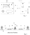
- Stretch-bend-straightening systems such as those in Fig. 3
- the system shown schematically are systems that are used to minimize internal tensions in ferrous and non-ferrous metallic strips and thereby achieve better flatness.
- Metallic bands are understood to mean any band-shaped materials.
- the term “metallic” includes metals per se as well as their alloys. Since the strips show unevenness after the previous rolling process, the straightening process is carried out. These unevenness are caused by fibers of different lengths in the material and are shown by wavy deformations in the strip. This is for explanation in the Figures 4a, 4b as Figures 5a to 5d shown.
- Has the band-shaped material 10 according to FIG Figure 4a Waves 12 are different fiber lengths according to Figure 4b responsible.
- the adjacent fibers have a different difference in length ⁇ L.
- These wavy deformations can appear in the strip-shaped material 10 as central waves 13 according to FIG Figure 5a , as edge waves 14 according to Figure 5b , as one-sided edge waves according to Figure 5c or as a combination of edge waves 14 and center waves 13.
- the stretch-bend-straightening system shown here generates a pull-up area in which the strip-shaped material 10 is stretched by means of a brake S-block 16 and a pull-S-block 18 that is fed from a coil arranged on a decoiler in the running direction 24 becomes.
- the designation “S” is used to clarify that the strip is guided around rollers in an S-shape in these areas.
- the tension that occurs is measured by a measuring device 22.
- the strip is subjected to 26 alternating bends in the bending and straightening unit. With these two measures, the shorter fibers are aligned with the longer ones and internal stresses are reduced.
- the strip-shaped material thus straightened is then wound up again on a recoiler 28.
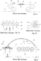
- an unevenness measuring system (UMS), which can be obtained from Ungerer Technology GmbH, can also be used according to the state of the art Fig. 8 can be used.
- This unevenness measuring system was specially designed to measure the unevenness of strips with relatively low specific strip tension. It determines the unevenness over the entire bandwidth of the product after the pull S-block 18 and is able to adjust the individual supports of the bending-straightening unit 26 so that an optimal straightening result is achieved.
- sensitive force sensors are used for the UMS, which are mounted on a fixed axis.
- a measuring roller 36 is preferably used for this.
- the controller C calculates the optimal parameters for the straightening process and thus regulates the setting of the supports, i.e. the support rollers 32, via a programmable logic controller PLC by means of a position controller 38.
- the UMS is as close as possible to the straightening process directly after the pull-S-block 18 in the pull-down area arranged in order to keep the dead distance 42 as small as possible.
- the dead distance is the distance that the material needs to get from the bending / straightening unit 26 to the measuring roller 36 before an unevenness can be determined on the measuring roller, which then starts a control process in a closed control loop.
- DE 22 03 911 A1 discloses a method and apparatus for controlling the flatness of a metal strip. Unevenness is detected by distance sensors and the immersion depth of the straightening rollers is then readjusted accordingly. This is done by intervening in a controlled system, but not by selecting a high pressure area or a pull-down area.
- Fig. 9 The measuring system shown is known, which is used in the high-tension area.
- a roller of the tension S-block 18 arranged after the bending and straightening unit 26 is replaced by a measuring roller 40.
- This roller consists of a massive body.
- the sensors are used on the circumference of the solid roller body and the entire running surface of the measuring roller 40 is covered with a PU coating.
- the sensors are able to detect the smallest differences in force in the belt.
- the force values determined are then transmitted to evaluation electronics as evaluation unit 34, processed there accordingly and transmitted to a controller C for calculating optimal parameters for the straightening process in a closed control loop.
- the advantage consists in a significantly shorter dead section 42 compared to the above-mentioned UMS system.
- the present invention is based on the object of designing a stretch-bending-straightening system and a method for its actuation in such a way that the quality of the strips processed with it is increased.
- the stretch-bending-straightening system has a feed means for feeding a strip-shaped material into a pull-up area and a pull-down area, the pull-down area being arranged downstream of the pull-up area in the running direction of the strip-shaped material.
- a bending and straightening unit is located in the pull-up area.
- a measuring system for determining first measured values in the pull-up area and a measuring system for determining second measured values in the pull-down area are provided.
- a controller is provided to determine the deviation of the first measured values from a predetermined or predeterminable target value of the bending alignment result and a controller is provided to determine the deviation of the second measured values from this target value.
- Manipulated variables are determined by the controller or controllers in order to minimize the deviations within closed control loops.
- at least two measuring systems are provided, one in a pull-up area and one in a pull-down area, in order to optimize the quality of the material to be processed as required.
- Selection means can be used to decide whether the first or the second closed control loop is used for optimization. Such a selection can be made according to certain criteria that are either based on empirical values or material parameters, but can also only be newly formed in the course of the process, since in the respective closed control loop in the pull-up area as well as in the pull-down area are measured at the same time, so that based on the parameters determined in this way an optimization can be selected. This allows a high quality tape to be produced in a simple and inexpensive manner.
- a single controller is preferably provided for the simultaneous determination of the deviation of the first and the second measured values from the setpoint value, so that the selection means alternatively select the first or the second control loop.
- the controller can without further synchronization between different regulators and controls an optimization can be carried out even in the case of small deviations in such a way that a switch is made from one control loop to the other.
- An evaluation unit is expediently provided for evaluating the first and / or the second measured values, that is to say more than one evaluation unit can also be provided.
- the selection means are thereby enabled to select the first or the second closed control loop as a function of the evaluation. Both manual and semi-automatic or automatic selection can be used as selection means, depending on the specifications given to the controller and the evaluation unit.
- display means are provided for displaying the first and second measured values and / or the selection means are provided for manual selection by an operator. This enables an operator to use the display to see at a glance where the measured values of the two measuring devices are currently moving and thus to decide whether to give preference to the first or the second control loop.
- the measuring system in the pull-up area is preferably formed by a measuring roller arranged after the bending / straightening unit. It is particularly advantageous if a roller of a tension S-block, which is usually arranged after the bending-straightening unit, is replaced by a measuring roller, on the circumference of which sensors are used and the running surface of which is covered with an elastic coating is. As a result, it can be determined almost immediately after the bending-straightening unit whether a good quality result is obtained in the pull-up area, so that the dead distance between the bending-straightening unit and the measuring system is shortened.
- the measuring roller is designed as part of the Werner-S-Block, no separate measuring system or no separate storage is required for such a roller; instead, the roller already present in the Werner-S-Block can be replaced by the measuring device, which further reduces the cost of the entire construction.
- the measuring system for determining the second measured values in the pull-down area is advantageously to be arranged after the pull-S-block, whereby it is arranged as close as possible to this block becomes. Such an arrangement helps to reduce the dead distance and thus the reject for this measuring system as well.
- the measuring roller used for this has measuring segments arranged next to one another with at least one sensor, preferably with two force sensors, since it is particularly important in the pull-down area to detect the differences over the bandwidth as precisely as possible over the entire area. While some deformations are not perceptible in the pull-up area due to the forces occurring there, these occur more frequently again under lower pulling forces in the pull-down area after elastic recovery and can therefore be clearly recognized there. In addition, a finer resolution is advantageous, which can be achieved by the arrangement of the measuring segments.
- the strip-shaped material is fed to the pull-up and pull-down area.
- First and second measured values are determined in the pull-up area as well as in the pull-down area, and a deviation from a target value is determined.
- a manipulated variable for the bending and straightening unit is calculated for both measuring systems, which can help optimize the result.
- predefined or predefinable criteria such as a deviation from the nominal value, but also empirical values or material parameters, it is then selected whether to work with the first or second closed control loop to achieve the desired result.
- the deviation of the first and second measured values is preferably determined simultaneously for both measuring systems by means of a single controller, so that the first or second closed control loop is selected as an alternative. According to the procedure, all information is therefore available at the same time in order to be able to make an informed decision.
- the first and second measured values are expediently evaluated according to predetermined criteria with a view to achieving a good result, the corresponding control loop then being selected as a function of the evaluation.
- criteria can initially be certain requirements for the quality of the strip to be processed, but they can also be material characteristics or empirical values that are specified by the operator or can be taken from expert knowledge that is possibly stored in a database.
- the first and second measured values are advantageously displayed to an operator at the same time, so that the operator can select the optimal control loop for the result to be achieved via selection means 48.
- This allows the operator to decide at a glance what is the best solution at the moment. Since this can change over the course of time even with a coil, this process can also be automated and monitored so that, if necessary, an indication of a suitable switchover time can be given to the operator.
- the method is initially operated on the basis of the first measured values from the pull-up area in a first closed control loop until the straightened strip-shaped material reaches the measuring roller in the pull-down area reached, so that it is then possible to switch to the second closed control loop in the pull-down area. Whether or not such a switchover is necessary at this moment can be determined on the basis of the measured values determined. The dead distance can be further reduced by such a configuration.
- Both the stretch-bending-straightening system and the method can be operated with a program that is set up and / or programmed with a program code in order to achieve the desired results and advantages when the program code is transferred to a computer, a processor or a programmable one Hardware component is running.
- both measuring systems for the pull-up and pull-down areas are combined for the first time.
- This system is preferably characterized by the use of a single controller C, but in principle several controllers can also be used.
- This preferably one controller C is able to evaluate the flatness measured values of the measuring roller 40 in the pull-up area 50 and of the measuring roller 36 in the pull-down area 52. The supports of the straightening machine are adjusted based on these values.
- the evaluation units 34 of the two measuring units are connected to the controller. This records the flatness values of the two units and uses the measured values of the active measuring unit to calculate the optimal parameters for the straightening process.
- the system operator preferably determines which of the two measuring units is to be used to regulate the straightening process. He is therefore able to use the more suitable measuring unit depending on the requirements and material and can also use this during a Change process. In order to be able to compare the two units for the respective process, it is possible to visualize the flatness measured values.
- the measured values of the measuring roller 36 in the pull-down area 52 and the measuring roller 40 in the pull-up area 50 are displayed graphically and / or as numerical values, preferably simultaneously, on a display unit 46.
- the system according to the invention thus achieves a more precise adaptation of the supports to the unevenness of the strip.
- Another advantage is that rejects can be permanently reduced in the case of materials for which better straightening results are achieved with the measuring roller 36 in the pull-down area 52.
- the measuring roller 40 is first activated in the pull-up area 50 and, after the dead section, it is switched to the measuring roller 36 in the pull-down area 52.
- the measuring roller 40 in the pull-up area 50 is suitable, for example, for high-strength materials. Since the tape is much stronger, the unevenness is not falsified by the high tension. Therefore, in this case, the measuring roller 40 can be used permanently in the pull-up area 50 and thus the advantage of the significantly shorter dead distance can be used.
- the controller C works with the values of the pull-up measuring roller 40, since its dead distance is significantly smaller.
- the dead path is understood to be the length of material that is required as a result of the controlled system from an actuating device, the bending / straightening unit 26, to the measuring point before a detected unevenness occurs a controller intervention on the bending-straightening unit 26 leads to an influence on the detected unevenness.
- the controller C adjusts the bending-straightening unit 26 accordingly with the calculated parameters in order to achieve the optimal straightening result.
- the controller C switches independently from the pull-up measuring roller 40 to the pull-down measuring roller 36 and regulates the support rollers 32 of the bending-straightening unit with the measured values of the pull-down measuring roller 36, if no other setting is specified by the operator via the input means 49 or by the stretch-bend-straightening system, for example on the basis of previous results already known from the machine.
- the system operator can intervene manually at any time via input means 49 and switch the controller C as desired. Using the input means 49, he can also enter and specify process data. Furthermore, the system operator can create a database 44 in which, for example, parameters for the process can be saved for materials that have been specified or have already been directed on the system. As a result, the controller C can independently select the optimal measuring roller 36 or measuring roller 40 for repetitive orders.
- further data can also be stored in the database 44, for example an assignment of certain operating parameters to certain materials or even expert knowledge.
- Expert knowledge is information on how an experienced operator would operate the stretch-bend-straightener and which parameters he would work with in order to achieve a good result.
- Further physical properties can also be entered here, such as the operating speed or temperature-dependent properties.
- both the measuring roller 40 in the pull-up area 50 and the measuring roller 36 in the pull-down area 52 are in engagement and display their measured values, it is possible to interpolate the measured values of the two measuring devices and have the software compare them with one another. This is made possible by, for example, forming an average value for each measuring device and determining this with defined limits at an interval of, for example, 50 control cycles.
- the controller C can then independently decide which measuring system is more suitable is. This switchover can take place automatically or a recommendation can be made to the system operator.
- Fig. 2 shows schematically a process sequence.
- step 100 strip-shaped material 10 is fed to a pull-up area 50 and a pull-down area 52.
- the material supplied in this way is measured in step 101 by means of a measuring device in the pull-up area, deviations in flatness being determined as first measured values.
- step 101 the strip-shaped material reaches the pull-down area 52 and there, in step 102, the deviations in flatness are also measured. This leads to the second measured values.
- step 103 the flatness deviations are compared with a target value for the flatness deviations. If the flatness deviation is less than or equal to the target value, the stretch-bend-straightener is operated with these operating parameters. If the target value is not adhered to, in step 104, preferably on the basis of predetermined criteria, it is selected whether the controlled system in the pull-up area or in the pull-down area will influence the result and thus the flatness deviation. Depending on which route is selected, the manipulated variable for the pull-up area 50 or the pull-down area 52 is calculated either in step 105 or in step 106.
- the manipulated variable is then applied to the bending and straightening unit 26 in step 107 and the method then jumps back to steps 101 and 102 in order to measure the deviations in flatness in the pull-up area 50 and in the pull-down area 52, respectively.
- the process then starts from the beginning.
Landscapes
- Engineering & Computer Science (AREA)
- Mechanical Engineering (AREA)
- Straightening Metal Sheet-Like Bodies (AREA)
Claims (16)
- Système d'étirement, de courbure et de redressement, doté- d'un système d'approvisionnement permettant l'approvisionnement d'un matériau (10) en forme de bande le long d'une direction de déplacement (24) dans une zone de traction élevée (50) et une zone de traction faible (52), dans lequel la zone de traction faible (52) est disposée en aval après la zone de traction élevée (50) dans la direction de déplacement (24),- d'un groupe de courbure et redressement (26), qui est disposé dans la zone de traction élevée (50),- d'au moins un système de mesure permettant la détermination de premières valeurs de mesure dans la zone de traction élevée (50),- d'un dispositif de commande (C), qui est destiné et approprié pour la détermination d'une déviation des premières valeurs de mesure par rapport à une valeur souhaitée prédéfinie ou pouvant être prédéfinie du résultat de la courbure et du redressement et pour la détermination d'au moins une grandeur de réglage pour le groupe de courbure et redressement (26) en fonction de la déviation déterminée dans une première boucle de réglage fermée, et- d'un moyen de réglage permettant d'avoir une influence sur la grandeur de réglage,- dans lequel, en complément, au moins un système de mesure est prévu pour la détermination de deuxièmes valeurs de mesure dans la zone de traction faible,caractérisé en ce qu'un dispositif de commande (C) est destiné et approprié pour la détermination d'une déviation des deuxièmes valeurs de mesure par rapport à une valeur souhaitée prédéfinie ou pouvant être prédéfinie du résultat de la courbure et du redressement et pour la détermination de l'au moins une grandeur de réglage en fonction de la déviation déterminée dans une deuxième boucle de réglage fermée, et que des moyens de sélection (48), qui sont destinés et appropriés pour sélectionner la première ou la deuxième boucle de réglage fermée, sont prévus pour la diminution de la déviation des premières et/ou deuxièmes valeurs de mesures par rapport à la valeur souhaitée prédéfinie ou pouvant être prédéfinie.
- Système d'étirement, de courbure et de redressement selon la revendication 1, caractérisé en ce que le dispositif de commande est un dispositif de commande (C) unique, qui est destiné et approprié pour la détermination simultanée de la déviation des premières et deuxièmes valeurs de mesure par rapport à la valeur souhaitée prédéfinie ou pouvant être prédéfinie, et que des moyens de sélection (48) sont destinés et appropriés pour sélectionner alternativement la première ou la deuxième boucle de réglage fermée.
- Système d'étirement, de courbure et de redressement selon la revendication 1 ou la revendication 2, caractérisé en ce qu'au moins une unité d'évaluation (34) est prévue pour l'évaluation des premières et deuxièmes valeurs de mesure et que les moyens de sélection (48) sont destinés et appropriés pour sélectionner, en fonction de l'évaluation, la première ou la deuxième boucle de réglage fermée.
- Système d'étirement, de courbure et de redressement selon l'une des revendications précédentes, caractérisé en ce que des moyens d'affichage (46) sont prévus pour l'affichage des premières et deuxièmes valeurs de mesure, et/ou que des moyens de sélection (48) sont prévus pour la sélection manuelle par un opérateur.
- Système d'étirement, de courbure et de redressement selon l'une des revendications précédentes, caractérisé en ce que l'au moins un système de mesure est conçu pour la détermination des premières valeurs de mesure dans la zone de traction élevée (50) par un rouleau de mesure (40) disposé après le groupe de courbure et redressement (26).
- Système d'étirement, de courbure et de redressement selon la revendication 5, caractérisé en ce qu'un rouleau d'un bloc de traction S (18) est remplacé par le rouleau de mesure (40), sur le périmètre duquel sont insérés des capteurs et dont la surface de roulement est recouverte d'un revêtement élastique.
- Système d'étirement, de courbure et de redressement selon l'une des revendications précédentes, caractérisé en ce que l'au moins un système de mesure est conçu pour la détermination des deuxièmes valeurs de mesure par un rouleau de mesure (36) disposé après le groupe de courbure et redressement (26) et après le bloc de traction S (18) dans la zone de traction faible (52).
- Système d'étirement, de courbure et de redressement selon la revendication 7, caractérisé en ce que l'au rouleau de mesure (36) présente des segments de mesure (36a) disposés les uns à côté des autres avec au moins un capteur, de préférence, avec deux capteurs de force.
- Système d'étirement, de courbure et de redressement selon l'une des revendications précédentes, caractérisé en ce que des moyens d'enregistrement sont prévus pour l'enregistrement des paramètres de fonctionnement réglés selon les première ou deuxième boucles de réglage fermées et qu'une banque de données (44) est prévue, qui est destinée et appropriée pour déposer ces paramètres de fonctionnement conjointement avec des données concernant le matériau travaillé avec ces paramètres de fonctionnement.
- Procédé pour la mise en oeuvre d'un système d'étirement, de courbure et de redressement selon l'une des revendications précédentes, avec les étapes :- d'approvisionnement d'un matériau (10) sous forme d'une bande le long d'une direction de déplacement (24) dans une zone de traction élevée (50) et une zone de traction faible (52), dans lequel un groupe de courbure et redressement (26) est disposé dans la zone de traction élevée (50), et dans lequel la zone de traction faible (52) est disposée en aval après la zone de traction élevée (50) dans la direction de déplacement (24)- de détermination de premières valeurs de mesure dans la zone de traction élevée (50),- de détermination d'une déviation des premières valeurs de mesure par rapport à une valeur souhaitée prédéfinie ou pouvant être prédéfinie du résultat de la courbure et du redressement,- de détermination d'au moins une grandeur de réglage pour le groupe de courbure et redressement (26) en fonction de la déviation déterminée dans une boucle de réglage fermée,- de détermination de deuxièmes valeurs de mesure dans la zone de traction faible (52),caractérisé par- la détermination d'une déviation des deuxièmes valeurs de mesure par rapport à une valeur souhaitée prédéfinie ou pouvant être prédéfinie du résultat de la courbure et du redressement,- la détermination de l'au moins une grandeur de réglage en fonction de la déviation déterminée dans une deuxième boucle de réglage fermée,- la sélection de la première ou de la deuxième boucle de réglage fermée pour la diminution de la déviation des premières et/ou deuxièmes valeurs de mesure par rapport à la valeur souhaitée prédéfinie ou pouvant être prédéfinie.
- Procédé selon la revendication 10, caractérisé en ce que la déviation des premières et deuxièmes valeurs de mesure par rapport à la valeur souhaitée prédéfinie ou pouvant être prédéfinie est déterminée simultanément au moyen d'un dispositif de commande (C) unique et que la première ou la deuxième boucle de réglage fermée est choisie alternativement.
- Procédé selon la revendication 10 ou la revendication 11, caractérisé en ce que les premières et deuxièmes valeurs de mesure sont évaluées selon des critères prédéterminés en ce qui concerne la production d'un résultat de la courbure et du redressement et que la première, ou la deuxième boucle de réglage fermée est choisie en fonction de l'évaluation.
- Procédé selon l'une des revendications 10 à 12, caractérisé en ce que les premières et deuxièmes valeurs de mesure sont affichées simultanément à un opérateur, et/ou que la première ou la deuxième boucle de réglage fermée peut être choisie manuellement par un opérateur.
- Procédé selon l'une des revendications précédentes, caractérisé en ce que le procédé fonctionne tout d'abord à l'aide des premières valeurs de mesure à partir de la zone de traction élevée (50) dans la première boucle de réglage fermée, jusqu'à ce que le matériau en forme de bande (10) ait atteint le rouleau de mesure (36) dans la zone de traction faible (52) et qu'ensuite on commute vers la deuxième boucle de réglage fermée dans la zone de traction faible (52).
- Procédé selon l'une des revendications précédentes, caractérisé par un enregistrement de paramètres de fonctionnement pour le système d'étirement de courbure et de redressement, déterminés déjà auparavant lors de la mise en œuvre du système d'étirement, de courbure et de redressement, conjointement avec des données concernant le matériau travaillé avec ces paramètres de fonctionnement dans une banque de données (44), et l'emploi des données enregistrées pour le travail de matériaux comparables.
- Programme avec un code de programme installé et/ou programmé pour la mise en œuvre du système d'étirement de courbure et de redressement selon l'une des revendications 1 à 9 et/ou pour l'exécution du procédé selon l'une des revendications 10 à 15, lorsque le code de programme est exécuté sur un ordinateur, un processeur ou un composant matériel programmable.
Applications Claiming Priority (3)
| Application Number | Priority Date | Filing Date | Title |
|---|---|---|---|
| DE102018101501 | 2018-01-23 | ||
| DE102018111627.6A DE102018111627A1 (de) | 2018-01-23 | 2018-05-15 | Streck-Biege-Richtanlage und Verfahren zu deren Betätigung |
| PCT/EP2019/051584 WO2019145338A1 (fr) | 2018-01-23 | 2019-01-23 | Système d'étirement, de courbure et de redressement et son procédé d'actionnement |
Publications (2)
| Publication Number | Publication Date |
|---|---|
| EP3720623A1 EP3720623A1 (fr) | 2020-10-14 |
| EP3720623B1 true EP3720623B1 (fr) | 2021-05-05 |
Family
ID=67144845
Family Applications (1)
| Application Number | Title | Priority Date | Filing Date |
|---|---|---|---|
| EP19702043.1A Active EP3720623B1 (fr) | 2018-01-23 | 2019-01-23 | Système d'étirement, de courbure et de redressement et son procédé d'actionnement |
Country Status (6)
| Country | Link |
|---|---|
| US (1) | US20210154716A1 (fr) |
| EP (1) | EP3720623B1 (fr) |
| CN (1) | CN110799277B (fr) |
| DE (1) | DE102018111627A1 (fr) |
| TW (1) | TW201936284A (fr) |
| WO (1) | WO2019145338A1 (fr) |
Families Citing this family (3)
| Publication number | Priority date | Publication date | Assignee | Title |
|---|---|---|---|---|
| DE102020007286B4 (de) | 2020-11-30 | 2023-05-04 | VDEh-Betriebsforschungsinstitut Gesellschaft mit beschränkter Haftung | Spannrollensatz für eine Richtanlage zum Richten eines Bandes, Richtanlage, Nachwalzgerüstanlage und Verfahren zum Betreiben einer Richtanlage |
| CN114505388B (zh) * | 2022-01-24 | 2022-10-21 | 燕山大学 | 用于板材的反复压弯校平装置及校平加工方法 |
| CN117732982B (zh) * | 2024-02-19 | 2024-05-10 | 四川腾邦科技有限公司 | 一种磁转动电机铁芯的多功能冲压系统及冲压方法 |
Family Cites Families (8)
| Publication number | Priority date | Publication date | Assignee | Title |
|---|---|---|---|---|
| BE790497A (fr) * | 1972-01-28 | 1973-02-15 | Bwg Bergwerk Walzwerk | Procede et dispositif pour la regulation de la planeite d'une bande metallique passant par une machine a dresser |
| JPS6120622A (ja) * | 1984-07-10 | 1986-01-29 | Mitsubishi Heavy Ind Ltd | テンシヨンレベラ制御方法 |
| DE19509067A1 (de) * | 1995-03-14 | 1996-09-19 | Bwg Bergwerk Walzwerk | Verfahren zum kontinuierlichen Richten von dünnen Metallbändern, insbesondere von Aluminium- und Edelstahl-Bändern mit Banddicken von 0,1 mm bis 0,5 mm, und Richtanlage zur Durchführung des Verfahrens |
| JP2001347318A (ja) * | 2000-06-08 | 2001-12-18 | Mitsubishi Heavy Ind Ltd | 板幅調整装置及び板幅調整方法 |
| DE102004043150A1 (de) * | 2004-09-03 | 2006-03-09 | Betriebsforschungsinstitut VDEh - Institut für angewandte Forschung GmbH | Spannrolle für eine Bandbehandlungsanlage sowie Bandbehandlungsanlage und Verwendung der Spannrolle |
| ITMI20062077A1 (it) * | 2006-10-30 | 2008-04-30 | Selema Srl | Sistema di stiramento e livellamento di una striscia metallica |
| DE102008045340A1 (de) * | 2008-09-01 | 2010-03-04 | Siemens Aktiengesellschaft | Betriebsverfahren für einen Streckrichter mit überlagerter Elongationsregelung und unterlagerter Zugregelung |
| DE102013106243C5 (de) * | 2013-06-14 | 2018-10-04 | Bwg Bergwerk- Und Walzwerk-Maschinenbau Gmbh | Verfahren und Vorrichtung zum Streckbiegerichten von Metallbändern |
-
2018
- 2018-05-15 DE DE102018111627.6A patent/DE102018111627A1/de not_active Withdrawn
-
2019
- 2019-01-21 TW TW108102257A patent/TW201936284A/zh unknown
- 2019-01-23 US US16/618,337 patent/US20210154716A1/en not_active Abandoned
- 2019-01-23 WO PCT/EP2019/051584 patent/WO2019145338A1/fr unknown
- 2019-01-23 EP EP19702043.1A patent/EP3720623B1/fr active Active
- 2019-01-23 CN CN201980003229.1A patent/CN110799277B/zh active Active
Also Published As
| Publication number | Publication date |
|---|---|
| TW201936284A (zh) | 2019-09-16 |
| DE102018111627A1 (de) | 2019-07-25 |
| WO2019145338A1 (fr) | 2019-08-01 |
| CN110799277A (zh) | 2020-02-14 |
| US20210154716A1 (en) | 2021-05-27 |
| CN110799277B (zh) | 2021-08-31 |
| EP3720623A1 (fr) | 2020-10-14 |
Similar Documents
| Publication | Publication Date | Title |
|---|---|---|
| EP3720623B1 (fr) | Système d'étirement, de courbure et de redressement et son procédé d'actionnement | |
| EP3210681B1 (fr) | Dispositif et procédé de laminage de matériau en bande à épaisseur variable | |
| EP3595824B1 (fr) | Procédé de fonctionnement d'une dresseuse à rouleaux | |
| EP2527053A1 (fr) | Procédé de commande pour une voie de laminage | |
| DE19653569C2 (de) | Verfahren zur automatisierten Führung eines Richtprozesses | |
| EP0121148A1 (fr) | Procédé pour la fabrication de feuillard à chaud avec section et planéité de bande de haute qualité | |
| EP1596999B2 (fr) | Procede de regulation de la temperature d'une bande metallique, en particulier dans un parcours de refroidissement | |
| EP2527054A1 (fr) | Procédé de commande pour une voie de laminage | |
| EP1711283B1 (fr) | Procede de reglage et mecanisme de reglage pour une cage de laminoir | |
| EP3122483B1 (fr) | Procédé permettant de positionner un galet de dressage d'une installation de dressage à galets | |
| DE19881041B4 (de) | Verfahren zur Steuerung und Voreinstellung eines Stahlwerkes oder von Teilen eines Stahlwerkes | |
| DE102017200365A1 (de) | Verfahren und Vorrichtung zum Richten eines Metallbandes | |
| DE102015223600A1 (de) | Verfahren zum Herstellen eines metallischen Bandes durch Endloswalzen | |
| EP4103339B1 (fr) | Détermination de la sensibilité d'une grandeur cible d'une matière à laminer pour un paramètre de fonctionnement d'un train de laminage à chaud | |
| EP1480767A1 (fr) | Procede de reduction des erreurs d'angle de pliage lors du pliage | |
| EP3566790B1 (fr) | Procédé de réglage dynamique d'écartement entre cylindres lors du laminage flexible de bandes métalliques | |
| DE3401894A1 (de) | Verfahren zum herstellen von walzband mit hoher bandprofil- und bandplanheitsguete | |
| EP1069963B1 (fr) | Procede et dispositif pour la production de segments de ressort a ruban cintres | |
| EP3494239B1 (fr) | Procédé de fonctionnement d'un four de recuit pour recuire une bande métallique | |
| EP3138639B1 (fr) | Procede de production d'une bande metallique par laminage en continu | |
| EP0272204B1 (fr) | Procédé de réglage d'épaisseur de paroi de tube | |
| EP3643418B1 (fr) | Machine à plier et son procédé de commande | |
| DE102022211278B3 (de) | Verfahren und Computerprogramm zum Anpassen des Soll-Dickenwertes für eine Regelung der Dicke eines neu zu walzenden Bandes für mindestens ein Walzgerüst | |
| EP4013556B1 (fr) | Procédé de détermination en ligne d'au moins un paramètre de laminage et laminoir doté d'un dispositif de détermination en ligne d'au moins un paramètre de laminage | |
| EP2512700B1 (fr) | Procédé permettant de faire fonctionner un cylindre enrouleur d'un four bobineur pour un laminoir à chaud fonctionnant de manière réversible, dispositif de commande et/ou de régulation et laminoir à chaud fonctionnant de manière réversible |
Legal Events
| Date | Code | Title | Description |
|---|---|---|---|
| STAA | Information on the status of an ep patent application or granted ep patent |
Free format text: STATUS: UNKNOWN |
|
| STAA | Information on the status of an ep patent application or granted ep patent |
Free format text: STATUS: THE INTERNATIONAL PUBLICATION HAS BEEN MADE |
|
| PUAI | Public reference made under article 153(3) epc to a published international application that has entered the european phase |
Free format text: ORIGINAL CODE: 0009012 |
|
| STAA | Information on the status of an ep patent application or granted ep patent |
Free format text: STATUS: REQUEST FOR EXAMINATION WAS MADE |
|
| 17P | Request for examination filed |
Effective date: 20191024 |
|
| AK | Designated contracting states |
Kind code of ref document: A1 Designated state(s): AL AT BE BG CH CY CZ DE DK EE ES FI FR GB GR HR HU IE IS IT LI LT LU LV MC MK MT NL NO PL PT RO RS SE SI SK SM TR |
|
| AX | Request for extension of the european patent |
Extension state: BA ME |
|
| GRAP | Despatch of communication of intention to grant a patent |
Free format text: ORIGINAL CODE: EPIDOSNIGR1 |
|
| STAA | Information on the status of an ep patent application or granted ep patent |
Free format text: STATUS: GRANT OF PATENT IS INTENDED |
|
| DAV | Request for validation of the european patent (deleted) | ||
| DAX | Request for extension of the european patent (deleted) | ||
| INTG | Intention to grant announced |
Effective date: 20201120 |
|
| GRAS | Grant fee paid |
Free format text: ORIGINAL CODE: EPIDOSNIGR3 |
|
| GRAA | (expected) grant |
Free format text: ORIGINAL CODE: 0009210 |
|
| STAA | Information on the status of an ep patent application or granted ep patent |
Free format text: STATUS: THE PATENT HAS BEEN GRANTED |
|
| AK | Designated contracting states |
Kind code of ref document: B1 Designated state(s): AL AT BE BG CH CY CZ DE DK EE ES FI FR GB GR HR HU IE IS IT LI LT LU LV MC MK MT NL NO PL PT RO RS SE SI SK SM TR |
|
| REG | Reference to a national code |
Ref country code: GB Ref legal event code: FG4D Free format text: NOT ENGLISH |
|
| REG | Reference to a national code |
Ref country code: CH Ref legal event code: EP |
|
| REG | Reference to a national code |
Ref country code: AT Ref legal event code: REF Ref document number: 1389155 Country of ref document: AT Kind code of ref document: T Effective date: 20210515 |
|
| REG | Reference to a national code |
Ref country code: IE Ref legal event code: FG4D Free format text: LANGUAGE OF EP DOCUMENT: GERMAN |
|
| REG | Reference to a national code |
Ref country code: DE Ref legal event code: R096 Ref document number: 502019001375 Country of ref document: DE |
|
| REG | Reference to a national code |
Ref country code: LT Ref legal event code: MG9D |
|
| PG25 | Lapsed in a contracting state [announced via postgrant information from national office to epo] |
Ref country code: FI Free format text: LAPSE BECAUSE OF FAILURE TO SUBMIT A TRANSLATION OF THE DESCRIPTION OR TO PAY THE FEE WITHIN THE PRESCRIBED TIME-LIMIT Effective date: 20210505 Ref country code: HR Free format text: LAPSE BECAUSE OF FAILURE TO SUBMIT A TRANSLATION OF THE DESCRIPTION OR TO PAY THE FEE WITHIN THE PRESCRIBED TIME-LIMIT Effective date: 20210505 Ref country code: LT Free format text: LAPSE BECAUSE OF FAILURE TO SUBMIT A TRANSLATION OF THE DESCRIPTION OR TO PAY THE FEE WITHIN THE PRESCRIBED TIME-LIMIT Effective date: 20210505 Ref country code: BG Free format text: LAPSE BECAUSE OF FAILURE TO SUBMIT A TRANSLATION OF THE DESCRIPTION OR TO PAY THE FEE WITHIN THE PRESCRIBED TIME-LIMIT Effective date: 20210805 |
|
| REG | Reference to a national code |
Ref country code: DE Ref legal event code: R082 Ref document number: 502019001375 Country of ref document: DE Representative=s name: UEXKUELL & STOLBERG PARTNERSCHAFT VON PATENT- , DE Ref country code: DE Ref legal event code: R081 Ref document number: 502019001375 Country of ref document: DE Owner name: VDEH-BETRIEBSFORSCHUNGSINSTITUT GMBH, DE Free format text: FORMER OWNER: LENZ, KLAUS, 47441 MOERS, DE Ref country code: DE Ref legal event code: R082 Ref document number: 502019001375 Country of ref document: DE Representative=s name: KOENIG SZYNKA TILMANN VON RENESSE PATENTANWAEL, DE |
|
| PG25 | Lapsed in a contracting state [announced via postgrant information from national office to epo] |
Ref country code: PL Free format text: LAPSE BECAUSE OF FAILURE TO SUBMIT A TRANSLATION OF THE DESCRIPTION OR TO PAY THE FEE WITHIN THE PRESCRIBED TIME-LIMIT Effective date: 20210505 Ref country code: LV Free format text: LAPSE BECAUSE OF FAILURE TO SUBMIT A TRANSLATION OF THE DESCRIPTION OR TO PAY THE FEE WITHIN THE PRESCRIBED TIME-LIMIT Effective date: 20210505 Ref country code: NO Free format text: LAPSE BECAUSE OF FAILURE TO SUBMIT A TRANSLATION OF THE DESCRIPTION OR TO PAY THE FEE WITHIN THE PRESCRIBED TIME-LIMIT Effective date: 20210805 Ref country code: PT Free format text: LAPSE BECAUSE OF FAILURE TO SUBMIT A TRANSLATION OF THE DESCRIPTION OR TO PAY THE FEE WITHIN THE PRESCRIBED TIME-LIMIT Effective date: 20210906 Ref country code: SE Free format text: LAPSE BECAUSE OF FAILURE TO SUBMIT A TRANSLATION OF THE DESCRIPTION OR TO PAY THE FEE WITHIN THE PRESCRIBED TIME-LIMIT Effective date: 20210505 Ref country code: RS Free format text: LAPSE BECAUSE OF FAILURE TO SUBMIT A TRANSLATION OF THE DESCRIPTION OR TO PAY THE FEE WITHIN THE PRESCRIBED TIME-LIMIT Effective date: 20210505 Ref country code: GR Free format text: LAPSE BECAUSE OF FAILURE TO SUBMIT A TRANSLATION OF THE DESCRIPTION OR TO PAY THE FEE WITHIN THE PRESCRIBED TIME-LIMIT Effective date: 20210806 Ref country code: IS Free format text: LAPSE BECAUSE OF FAILURE TO SUBMIT A TRANSLATION OF THE DESCRIPTION OR TO PAY THE FEE WITHIN THE PRESCRIBED TIME-LIMIT Effective date: 20210905 |
|
| REG | Reference to a national code |
Ref country code: NL Ref legal event code: MP Effective date: 20210505 |
|
| REG | Reference to a national code |
Ref country code: CH Ref legal event code: PK Free format text: BERICHTIGUNGEN |
|
| PG25 | Lapsed in a contracting state [announced via postgrant information from national office to epo] |
Ref country code: NL Free format text: LAPSE BECAUSE OF FAILURE TO SUBMIT A TRANSLATION OF THE DESCRIPTION OR TO PAY THE FEE WITHIN THE PRESCRIBED TIME-LIMIT Effective date: 20210505 |
|
| RAP2 | Party data changed (patent owner data changed or rights of a patent transferred) |
Owner name: VDEH-BETRIEBSFORSCHUNGSINSTITUT GMBH |
|
| RIN2 | Information on inventor provided after grant (corrected) |
Inventor name: LATHE, ROGER Inventor name: MUECKE, GERT Inventor name: LENZ, KLAUS |
|
| PG25 | Lapsed in a contracting state [announced via postgrant information from national office to epo] |
Ref country code: SK Free format text: LAPSE BECAUSE OF FAILURE TO SUBMIT A TRANSLATION OF THE DESCRIPTION OR TO PAY THE FEE WITHIN THE PRESCRIBED TIME-LIMIT Effective date: 20210505 Ref country code: EE Free format text: LAPSE BECAUSE OF FAILURE TO SUBMIT A TRANSLATION OF THE DESCRIPTION OR TO PAY THE FEE WITHIN THE PRESCRIBED TIME-LIMIT Effective date: 20210505 Ref country code: ES Free format text: LAPSE BECAUSE OF FAILURE TO SUBMIT A TRANSLATION OF THE DESCRIPTION OR TO PAY THE FEE WITHIN THE PRESCRIBED TIME-LIMIT Effective date: 20210505 Ref country code: SM Free format text: LAPSE BECAUSE OF FAILURE TO SUBMIT A TRANSLATION OF THE DESCRIPTION OR TO PAY THE FEE WITHIN THE PRESCRIBED TIME-LIMIT Effective date: 20210505 Ref country code: RO Free format text: LAPSE BECAUSE OF FAILURE TO SUBMIT A TRANSLATION OF THE DESCRIPTION OR TO PAY THE FEE WITHIN THE PRESCRIBED TIME-LIMIT Effective date: 20210505 Ref country code: CZ Free format text: LAPSE BECAUSE OF FAILURE TO SUBMIT A TRANSLATION OF THE DESCRIPTION OR TO PAY THE FEE WITHIN THE PRESCRIBED TIME-LIMIT Effective date: 20210505 Ref country code: DK Free format text: LAPSE BECAUSE OF FAILURE TO SUBMIT A TRANSLATION OF THE DESCRIPTION OR TO PAY THE FEE WITHIN THE PRESCRIBED TIME-LIMIT Effective date: 20210505 |
|
| REG | Reference to a national code |
Ref country code: DE Ref legal event code: R097 Ref document number: 502019001375 Country of ref document: DE |
|
| REG | Reference to a national code |
Ref country code: GB Ref legal event code: 732E Free format text: REGISTERED BETWEEN 20220113 AND 20220119 |
|
| PLBE | No opposition filed within time limit |
Free format text: ORIGINAL CODE: 0009261 |
|
| STAA | Information on the status of an ep patent application or granted ep patent |
Free format text: STATUS: NO OPPOSITION FILED WITHIN TIME LIMIT |
|
| 26N | No opposition filed |
Effective date: 20220208 |
|
| PG25 | Lapsed in a contracting state [announced via postgrant information from national office to epo] |
Ref country code: IS Free format text: LAPSE BECAUSE OF FAILURE TO SUBMIT A TRANSLATION OF THE DESCRIPTION OR TO PAY THE FEE WITHIN THE PRESCRIBED TIME-LIMIT Effective date: 20210905 Ref country code: AL Free format text: LAPSE BECAUSE OF FAILURE TO SUBMIT A TRANSLATION OF THE DESCRIPTION OR TO PAY THE FEE WITHIN THE PRESCRIBED TIME-LIMIT Effective date: 20210505 |
|
| PG25 | Lapsed in a contracting state [announced via postgrant information from national office to epo] |
Ref country code: IT Free format text: LAPSE BECAUSE OF FAILURE TO SUBMIT A TRANSLATION OF THE DESCRIPTION OR TO PAY THE FEE WITHIN THE PRESCRIBED TIME-LIMIT Effective date: 20210505 |
|
| PG25 | Lapsed in a contracting state [announced via postgrant information from national office to epo] |
Ref country code: MC Free format text: LAPSE BECAUSE OF FAILURE TO SUBMIT A TRANSLATION OF THE DESCRIPTION OR TO PAY THE FEE WITHIN THE PRESCRIBED TIME-LIMIT Effective date: 20210505 |
|
| REG | Reference to a national code |
Ref country code: BE Ref legal event code: MM Effective date: 20220131 |
|
| PG25 | Lapsed in a contracting state [announced via postgrant information from national office to epo] |
Ref country code: LU Free format text: LAPSE BECAUSE OF NON-PAYMENT OF DUE FEES Effective date: 20220123 |
|
| REG | Reference to a national code |
Ref country code: DE Ref legal event code: R082 Ref document number: 502019001375 Country of ref document: DE Representative=s name: UEXKUELL & STOLBERG PARTNERSCHAFT VON PATENT- , DE |
|
| PG25 | Lapsed in a contracting state [announced via postgrant information from national office to epo] |
Ref country code: BE Free format text: LAPSE BECAUSE OF NON-PAYMENT OF DUE FEES Effective date: 20220131 |
|
| PG25 | Lapsed in a contracting state [announced via postgrant information from national office to epo] |
Ref country code: IE Free format text: LAPSE BECAUSE OF NON-PAYMENT OF DUE FEES Effective date: 20220123 |
|
| PGFP | Annual fee paid to national office [announced via postgrant information from national office to epo] |
Ref country code: FR Payment date: 20230123 Year of fee payment: 5 |
|
| PGFP | Annual fee paid to national office [announced via postgrant information from national office to epo] |
Ref country code: AT Payment date: 20240118 Year of fee payment: 6 |
|
| PG25 | Lapsed in a contracting state [announced via postgrant information from national office to epo] |
Ref country code: MK Free format text: LAPSE BECAUSE OF FAILURE TO SUBMIT A TRANSLATION OF THE DESCRIPTION OR TO PAY THE FEE WITHIN THE PRESCRIBED TIME-LIMIT Effective date: 20210505 Ref country code: CY Free format text: LAPSE BECAUSE OF FAILURE TO SUBMIT A TRANSLATION OF THE DESCRIPTION OR TO PAY THE FEE WITHIN THE PRESCRIBED TIME-LIMIT Effective date: 20210505 |
|
| PGFP | Annual fee paid to national office [announced via postgrant information from national office to epo] |
Ref country code: DE Payment date: 20240119 Year of fee payment: 6 Ref country code: GB Payment date: 20240124 Year of fee payment: 6 Ref country code: CH Payment date: 20240202 Year of fee payment: 6 |