EP3718871A1 - Protection individuelle contre les intemperies - Google Patents
Protection individuelle contre les intemperies Download PDFInfo
- Publication number
- EP3718871A1 EP3718871A1 EP20166024.8A EP20166024A EP3718871A1 EP 3718871 A1 EP3718871 A1 EP 3718871A1 EP 20166024 A EP20166024 A EP 20166024A EP 3718871 A1 EP3718871 A1 EP 3718871A1
- Authority
- EP
- European Patent Office
- Prior art keywords
- flexible wall
- frame
- wall
- user
- protective
- Prior art date
- Legal status (The legal status is an assumption and is not a legal conclusion. Google has not performed a legal analysis and makes no representation as to the accuracy of the status listed.)
- Granted
Links
Images



Classifications
-
- B—PERFORMING OPERATIONS; TRANSPORTING
- B62—LAND VEHICLES FOR TRAVELLING OTHERWISE THAN ON RAILS
- B62J—CYCLE SADDLES OR SEATS; AUXILIARY DEVICES OR ACCESSORIES SPECIALLY ADAPTED TO CYCLES AND NOT OTHERWISE PROVIDED FOR, e.g. ARTICLE CARRIERS OR CYCLE PROTECTORS
- B62J17/00—Weather guards for riders; Fairings or stream-lining parts not otherwise provided for
- B62J17/08—Hoods protecting the rider
- B62J17/083—Frame mounted hoods specially adapted for rider propelled cycles
-
- B—PERFORMING OPERATIONS; TRANSPORTING
- B62—LAND VEHICLES FOR TRAVELLING OTHERWISE THAN ON RAILS
- B62J—CYCLE SADDLES OR SEATS; AUXILIARY DEVICES OR ACCESSORIES SPECIALLY ADAPTED TO CYCLES AND NOT OTHERWISE PROVIDED FOR, e.g. ARTICLE CARRIERS OR CYCLE PROTECTORS
- B62J17/00—Weather guards for riders; Fairings or stream-lining parts not otherwise provided for
- B62J17/08—Hoods protecting the rider
Definitions
- the present invention relates to personal protection against bad weather, intended to be worn by the user and attached to the steering means of a mobile machine.
- the present invention provides an individual protection device, making it possible to overcome the aforementioned drawbacks.
- the invention thus relates to an individual protection device against bad weather intended for the protection of a user using a rolling machine, the device comprising a protective wall, characterized in that the device is worn on the back of the vehicle.
- a carrying system comprising carrying straps and is constituted by a flexible wall which extends from the carrying system to position itself above the head of the user up to the front while means of fixing are provided to fix the free front end of the protective wall to the steering member of the rolling machine.
- the protective device thus obtained is light, easily transported and installed, and dynamically adapts to the position of the user when moving.
- the device according to the invention can also have one or more of the following characteristics.
- the flexible wall may comprise a frame formed by at least one elastically deformable flexible rod.
- the device is then collapsible into a more compact configuration for its transport.
- the frame can be formed by two flexible lateral rods which are elastically deformable.
- the side edges of the protective wall can be attached to the frame.
- the rigidity of the device is then improved in the deployed state.
- the flexible wall can be held by the frame over its entire periphery.
- the frame may include a plurality of interlocking tensioning arches made of a pre-stressed elastic flexible material forming, in the deployed state, a semi-rigid frame, and the device then comprises side skirts which delimit the curvature of the device while limiting the relaxation of the tensioning arches.
- the device thus obtained folds up by twisting the eight-shaped hoops, and deploys spontaneously under the action of said hoops.
- One of the tensioning arches can form a frame for a stretched portion of the flexible wall of the device in the deployed state.
- the rigidity of the device is then improved in the deployed state.
- One of the tensioning arches can form a frame for a transparent front portion of flexible wall so as to form a transparent windshield.
- the tensioning arches may be tangent or in contact around the front end of the device, at the level of the means for fixing to the steering means.
- the rigidity of the front part is then improved, and the folding of the device is simplified.
- the flexible wall may include a cross member.
- the carrying system may include a back wall.
- the frame can be made of fiberglass.
- the flexible wall may include a rear skirt protecting the lower back and the pelvis of the user.
- the rear skirt can form at least part of a cover accommodating the frame and the flexible wall in the folded state.
- the fixing means comprise at least one of the following: an elastic strap, a self-gripping band with textile loops and hooks, a reversible fastener with cooperation of shape, a tightening loop, hooks cooperating with the steering means by form cooperation.
- Fixing the device to the rolling machine is then quick, easily reversible, and does not require tools.
- the figure 1 is a perspective view, in use, of the personal protection device, according to one embodiment of the invention.
- the figure 2 is a front view and unfolded flat of the personal protection device.
- the figure 3 is a front view of the personal protection device, according to one embodiment of the invention.
- the figure 4 is a three-quarter front view of a device according to a variant of the invention.
- the figure 5 is a rear three-quarter view of the variant of the figure 4 in use, with a mobile machine and a user.
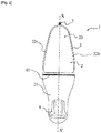
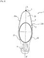
- the figure schematically illustrates the folding of the device according to the variant of figures 4 and 5 .
- the device (1) for personal protection against bad weather comprises a flexible wall (2), a frame (3), a carrying system (4) and a means of attachment (5) to the management body (MD) of a mobile machine (EM).
- MD management body
- EM mobile machine
- the flexible wall (2) constitutes the protective wall for the user (U).
- the latter consists of a layer of a flexible and deformable material and extends from the carrying system (4) to position itself above the user's head and to extend forward in the direction of of the steering means of the mobile machine, to which the free end of the device is intended to be fixed.
- the device (1) of the invention is carried on the back of the user (U) to be fixed in the protective position to a mobile device, such as a cycle, a scooter or a stroller.
- a mobile device such as a cycle, a scooter or a stroller.
- the flexible protective wall (2) is worn by the user and is therefore integral with it and follows its movements, its orientation is optimized according to the user's practice.
- the device (1) follows the movements of the user, in particular on a bicycle, both in a seated position in the saddle, and in a standing position. pedals in which the flexible wall (2) stretches upward, that leaning forward in which the flexible wall (2) bends forward.
- the flexible wall (2) has a longitudinal profile, with a longitudinal axis (X, X ') of symmetry, having a length greater than its width.
- the flexible wall (2) comprises a rear part (21) intended to be assembled to the carrying system (4), a front part (23) comprising the fixing means (5) intended to be fixed to the mobile vehicle, thus as side edges (22a, 22b), namely a right side border (22a) and a left side border (22b).
- the flexible wall is at least partly made of transparent material, such as for example PVC (polyvinyl chloride).
- the carrying system (4) is of the type of a back wall of a backpack, provided with carrying straps as illustrated.
- the length of the flexible wall (2) along the longitudinal axis (X, X ') is greater than 150 centimeters, preferably greater than 180 centimeters.
- the length of the flexible wall (2) is between 180 and 220 centimeters.
- the widest part of the flexible wall (2) is between 60 and 80 centimeters.
- the flexible wall has the shape of an ogive, namely that the widest part is located at approximately 50% of its length along the longitudinal axis (X, X ') intended to come to be positioned directly above the user, and tapers towards the front part (23) and towards the rear part.
- the width of the first quarter of the flexible wall (2), at the level of the carrying system (4), corresponding to a portion of the rear part (21) of the flexible wall (2) is between 30 and 50 centimeters.
- the preceding characteristic makes it possible to bring aerodynamics to the device (1), not hampering the user's progress and reducing wind resistance.
- the flexible wall (2) extends from the carrying system (4) and extends forward.
- the flexible wall (2) is intended to cover the back of the user.
- the flexible wall (2) extends on either side of the carrying system (4) along the longitudinal axis (X, X ').
- the flexible wall (2) is intended to cover the back of the user and extend rearwardly to prevent the user against projections coming from the rear axle of the mobile machine.
- the proximal end of the rear part (21) of the flexible wall (2) substantially coincides with the lower end of the carrying system (4).
- At least one third of the length of the flexible wall (2) is transparent. Soft portions of less than a third may be sufficient to form a visor.
- At least the front part (23) of the flexible wall (2) is transparent, in order to ensure the front visibility of the user
- At least fifty percent of the length of the flexible wall (2) is transparent.
- the flexible wall (2) is assembled with at least one frame (3).
- the frame (3) consists of two flexible lateral rods, elastically deformable, extending from the end of the rear part (21) to the end of the front part (23).
- the flexible wall (2) is held over its entire periphery by a frame (3), thanks to two side rods which in the position of use and protection are curved facing one of the the other so that their respective ends are connected.
- the frame (3) is U-shaped and extends from the rear end of the right side edge (22a), extends towards the front part (23) and is extends towards the rear end of the left side wall (22b).
- rods forming the frame are made of an elastically deformable material, and are for example made of fiberglass.
- the rod has a diameter of between 2 and 8 millimeters, preferably between 4 and 6 millimeters.
- the flexible wall (2) is thus held by the frame (3) at its lateral ends in a curved position, the flexible wall (2) may have a tendency to sag towards the head of the user, along of the longitudinal axis (X, X ').
- the device (1) comprises means for tensioning (61, 62) the flexible wall (2).
- the tensioning means is a cross member (61) arranged perpendicular to the longitudinal axis (X, X ').
- the cross member (61) extends over the width of the flexible wall (2) and connects the frame (3) on either side.
- crossmember (61) is made of a flexible elastically deformable material.
- crossmember (61) could be made in two short lengths connected together in the use position, so that the disconnection of the strands allows their storage in the carrying system.
- the cross member (61) is intended to come into position directly above the user, and allows better retention of the flexible wall in the position of use.
- the cross member (61) is located between a quarter and half of the length of the flexible wall (2), at the level of the rear part (21), preferably between a third and half of the length of the the flexible wall (2).
- the means of tensioning the flexible wall (2) is a hoop (62).
- the arch (62) extends from the lower end of the rear part (21) of the flexible wall (2) towards the front, in the direction of the fixing means (5) .
- the distal end of the arch (62), along the longitudinal axis (X, X ') extends to approximately one third of the length of the flexible wall (2).
- the carrying system (4) is a harness, such as for example of the type of a back wall of a backpack, provided with carrying straps (40a, 40b) as illustrated, and optionally further maintained by an additional waist strap (40).
- the harness is integrated into a backpack.
- the backpack advantageously comprises a compartment in which the flexible wall (2) afterwards is intended to be housed when the device (1) is folded in the position of non-use. It should be noted that, thanks to the flexibility of the elements constituting the individual protection, it is possible to fold the entire device back on itself.
- the carrying system (4) is removable, for example with a self-releasing disconnection system aiming to separate the shoulder straps from the back of the carrying system.
- the device (1) comprises a means for storing the flexible wall (2), located on the side opposite to that equipped with the carrying system (4).
- the carrying system (4) could also have pockets or storage compartment for various clothes or objects.
- the storage means is either an elastic wall comprising an orifice, or two elastic walls delimiting an opening, advantageously intended to be associated by a closure means.
- the fixing means (5) is an elastic strap or a self-gripping band with loops and textile hooks, for example, a reversible fastener with cooperation of shape (“clips”), a tightening loop, hooks. cooperating with the directing medium (MD) by form cooperation etc.
- the free lateral ends of the front part (23) each comprise a fixing means (5).
- the previous feature allows a connection to the steering means (MD) of the mobile machine as simple as possible in a very short time.
- This feature allows installation on any mobile device, scooter or stroller, without having to first install a connection structure to a specific mobile device.
- the figures 4 and 5 are three-quarter representations of the front and rear respectively of a particular embodiment of the device (1) for personal protection.
- the device is shown on its own, in the deployed state, ready to be installed on a mobile machine.
- the device is in use, and a user (U) carrying the device (1) and a mobile device connected to said device (1) are diagrammatically represented.
- the frame (3) of the device (1) for the individual protection of figures 4 and 5 comprises a plurality of tensioning arches (31, 33, 35) made of elastic flexible material and pre-stressed, here in particular three in number, of oval, elliptical or oblong shape.
- tensioning arches (31, 33, 35) are nested and coplanar with the flexible wall, so as to form a semi-rigid frame in the deployed state of the device (1).
- the tensioning arches (31, 33, 35) are also tangent or in contact around the front end of the device (1), at the level of the fixing means (5) by the steering means (MD).
- the tensioning hoops (31, 33, 35) of the figures 4 and 5 are in particular parallel and close enough to be able to be integrated into a single hem or a single fold of the flexible wall (2) over part of its front portion (21) over several tens of centimeters at the front end.
- the three tensioning arches (31, 33, 35) can according to a particular embodiment be loops of a single rod folded back on itself, or be composed of nested half-rods.
- the device (1) according to the invention can be used on any mobile, rental or self-service machine, by simply connecting the fixing means (5) to its steering means (MD).
- the smallest of the tensioning hoops (31) forms an oval or oblong frame for the transparent front portion (23) of the flexible wall (2), so as to form a windshield making it possible to maintain visibility towards the front for the user (U) while ensuring its protection against bad weather, framed by said smallest of the tensioning arches (31).
- the transparent front portion (23) of the flexible wall (2) can in particular be hemmed or more generally fixed around the smallest of the hoops (31) for a simplified assembly of the device (1).
- the intermediate arch (33) forms an additional stiffening structural element, making it possible to tension the flexible wall in order to ensure a curved shape above the user's head (U).
- the device (1) further comprises two side skirts (27) fixed laterally along the longitudinal edges on either side of the flexible wall (2).
- the side skirts (27) can, for example, be sewn, glued, welded or made from one material, with the flexible wall (2). These side skirts (27) are in particular crescent-shaped.
- the side skirts (27) are made of inextensible material and are stretched in the unfolded state of the device (1). The side skirts (27) thus delimit the curvature of the device (1) by limiting the relaxation of the pre-stressed tensioning arches (31, 33, 35), and thus contribute to the rigidity of the device (1).
- Side skirts (27, 29) of different shape, with larger surfaces, and / or forming a partial lateral closure are also possible.
- the rear portion (23) of the flexible wall (2) extends into a rear skirt (25) beyond the largest of the arches (35).
- the rear skirt (25) protects in particular the lower back and the pelvis of the user (U), in particular from water coming from the ground, for example raised by the rear wheel.
- the rear skirt (25) forms in the embodiment of figures 4 and 5 at least part of a protective cover, substantially circular, in which the device (1) can be placed in the folded state.
- the rear skirt (25) can also be padded and form a seat placed on the saddle on which the user (U) sits down to avoid contact with the wet saddle of the mobile device.
- the device (1) according to the invention does not require the initial installation of fasteners to the mobile device, which are assembled with complementary fasteners located on a protective bubble.
- the device (1) according to the invention can be used on any mobile, rental or self-service machine, by simply connecting the fixing means (5) to its steering means (MD).
- the folding of the device (1) of the embodiment of figures 4 and 5 is carried out in particular by twisting around the longitudinal axis (X, X ') then folding the tensioning arches (31, 33, 35) twisted in the form of eight on themselves.
- This fallback mode is particularly similar to the folding of tents with rapid deployment and sun visors with a pre-stressed flexible frame. Different stages of the withdrawal are briefly illustrated in figure 6 .
- the flexible wall (2) and the tensioning arches (31, 33, 35) thus folded are then inserted into the protective cover, which is advantageously a portion of the rear skirt (25), which cover then maintains the tensioning arches (31, 33, 35) in the folded state.
- the protective cover can in particular be separated from the rest of the device (1). The device is thus all-in-one.
- the flexible wall (2) and the tensioning arches (31, 33, 35), in the folded state, are taken out of the protective cover.
- the prestressed tensioning arches (31, 33, 35) relax and spontaneously deploy the device (1) by tensioning the flexible wall (2).
- the device In the folded state, the device is easily transportable, in particular by forming a backpack with the straps (40a, 40b), or as such in the form of a transport bag, attached by means of additional loops or fasteners (for example). example by means of a clip to the luggage rack of a bicycle).
- a particular embodiment provides for a reversible release attachment of the straps (40a, 40b) when a force greater than a limit value is applied to them.
- the straps (40a, 40b) may, for example, comprise form-cooperation release loops (clips), one half of which is connected to a portion of the strap by bands with textile loops and hooks. The buckles of the shoulder straps can then be easily changed.
- the straps (40a, 40b) are released in a reversible manner so as to avoid an accident or accident without rendering the device (1) unusable subsequently.
- the device (1) according to the invention allows easier descent and ascent on the mobile machine.
- the user passes one of his legs over the rear wheel in order to be able to sit on the saddle, which seems difficult in the presence of a structure connected to the part. rear of a bicycle.
- the device (1) according to the invention being worn by the user and detached from the mobile device, when it is not in use, the risks of damage and theft compared to a fixed structure are limited or even nil.
Landscapes
- Engineering & Computer Science (AREA)
- Mechanical Engineering (AREA)
- Professional, Industrial, Or Sporting Protective Garments (AREA)
- Body Structure For Vehicles (AREA)
Abstract
Description
- La présente invention concerne une protection individuelle contre les intempéries, destinée à être portée par l'utilisateur et fixée au moyen de direction d'un engin mobile.
- Dès l'invention de la bicyclette dans la deuxième moitié du 19ème siècle, des systèmes de protection contre les intempéries spécifiques à ces engins mobiles ont été développés, par exemple des fixations de parapluie au cadre du vélocipède, qui apportaient une protection contre la pluie toute relative.
- Des structures plus imposantes, sous des formes de coques de protection, rigides et forcément lourdes avec les moyens de l'époque amélioraient cette protection recherchée contre les intempéries, telles que divulguées par les documents
FR 867 497 FR 876 786 - Récemment, des structures disponibles dans le commerce, plus légères, basées sur une bulle de protection, ont vu le jour, répondant à des problématiques de légèreté, de coût et de relative facilité d'installation selon les modèles proposés.
- Ces structures se présentent par une toile munie d'armatures, reliées à l'avant et à l'arrière d'un vélo. Ces structures sont assemblées au vélo par des systèmes de fixation qui doivent être préinstallés et qui restent en place, une fois la toile et les armatures retirées.
- Ces structures sont en général destinées à un vélo personnel et ne permettent ainsi pas, ou en tout cas pas de manière aisée, d'être installées sur des vélos de location ou en libre-service.
- En outre, ces structures bien qu'efficaces, restent disponibles à un coût relativement élevé, ce qui semble limiter leur impact sur le plus grand nombre.
- La présente invention propose un dispositif de protection individuelle, permettant de pallier les inconvénients précités.
- L'invention se rapporte ainsi à un dispositif de protection individuelle contre les intempéries destiné à la protection d'un utilisateur utilisant un engin roulant, le dispositif comprenant une paroi de protection, caractérisé en ce que le dispositif est porté sur le dos de l'utilisateur par un système de portage comportant des bretelles de portage et est constitué par une paroi souple qui s'étend depuis le système de portage pour se positionner au-dessus de la tête de l'utilisateur jusque vers l'avant tandis que des moyens de fixation sont prévus pour fixer l'extrémité libre avant de la paroi de protection à l'organe de direction de l'engin roulant.
- Le dispositif de protection ainsi obtenu est léger, aisément transporté et installé, et s'adapte de façon dynamique à la position de l'utilisateur lors de ses déplacements.
- Le dispositif selon l'invention peut en outre présenter une ou plusieurs des caractéristiques suivantes.
- La paroi souple peut comprendre une armature constituée par au moins une tige flexible déformable élastiquement.
- Le dispositif est alors repliable en une configuration plus compacte pour son transport.
- L'armature peut être constituée par deux tiges flexibles latérales déformables élastiquement.
- Les bordures latérales de la paroi de protection peuvent être fixées à l'armature.
- La rigidité du dispositif est alors améliorée à l'état déployé.
- La paroi souple peut être maintenue par l'armature sur toute sa périphérie.
- En alternative, l'armature peut comporter une pluralité d'arceaux tendeurs imbriqués en matériau souple élastique précontraints formant, à l'état déployé une armature semi-rigide, et le dispositif comporte alors des jupes latérales qui délimitent la courbure du dispositif en limitant la détente des arceaux tendeurs.
- Le dispositif ainsi obtenu se replie par torsion des arceaux en forme de huit, et se déploie spontanément sous l'action desdits arceaux.
- Un des arceaux tendeurs peut former un cadre pour une portion tendue à l'état déployé de la paroi souple du dispositif.
- La rigidité du dispositif est alors améliorée à l'état déployé.
- Un des arceaux tendeurs peut former un cadre pour une portion avant transparente de paroi souple de sorte à former un pare-brise transparent.
- L'assemblage du dispositif est alors simplifié.
- Les arceaux tendeurs peuvent être tangents ou en contact autour de l'extrémité avant du dispositif, au niveau des moyens de fixation au moyen de direction.
- La rigidité de la partie avant est alors améliorée, et le repliage du dispositif est simplifié.
- La paroi souple peut comprendre une traverse.
- Le système de portage peut comporter une paroi dorsale.
- L'armature peut être réalisée en fibre de verre.
- La paroi souple peut comporter une jupe arrière protégeant le bas du dos et le bassin de l'utilisateur.
- La jupe arrière peut former au moins une partie d'une housse accueillant l'armature et la paroi souple à l'état replié.
- D'autres caractéristiques et avantages de l'invention se dégageront de la description qui va suivre en regard des dessins annexés qui ne sont donnés qu'à titre d'exemples non limitatifs.
- Les moyens de fixation comportent l'un au moins des suivants : une sangle élastique, une bande auto-agrippante à boucles et crochets textiles, une attache réversible à coopération de forme, une boucle de serrage, des crochets coopérant avec le moyen de direction par coopération de forme.
- La fixation du dispositif à l'engin roulant est alors rapide, aisément réversible, et ne nécessite pas d'outils.
- La
figure 1 est une vue en perspective, en cours d'utilisation, du dispositif de protection individuelle, selon un mode de réalisation de l'invention. - La
figure 2 est une vue de face et déployée à plat du dispositif de protection individuelle. - La
figure 3 est une vue de face du dispositif de protection individuelle, selon un mode d'exécution de l'invention, - La
figure 4 est une vue de trois-quarts avant d'un dispositif selon une variante de l'invention, - La
figure 5 est une vue de trois-quarts arrière de la variante de lafigure 4 en cours d'utilisation, avec un engin mobile et un utilisateur. - La figure illustre schématiquement le repliage du dispositif selon la variante des
figures 4 et5 . - Ainsi, le dispositif (1) de protection individuelle contre les intempéries selon l'invention, comprend une paroi souple (2), une armature (3), un système de portage (4) et un moyen de fixation (5) à l'organe de direction (MD) d'un engin mobile (EM).
- Il est entendu par organe de direction, des poignées, un guidon ou une potence.
- Ajoutons que tel qu'illustré à la
figure 1 , la paroi souple (2) constitue la paroi de protection pour l'utilisateur (U). Cette dernière est constituée par une couche d'un matériau souple et déformable et s'étend depuis le système de portage (4) pour se positionner au-dessus de la tête de l'utilisateur et à s'étendre vers l'avant en direction du moyen de direction de l'engin mobile, à laquelle l'extrémité libre du dispositif est destinée à être fixée. - Le dispositif (1) de l'invention est porté sur le dos de l'utilisateur (U) pour être fixé en position de protection à un engin mobile, tel qu'un cycle, une trottinette ou une poussette.
- La paroi souple (2) de protection est portée par l'utilisateur et lui est donc solidaire et suit ses mouvements, son orientation est optimisée selon la pratique de l'utilisateur.
- Ainsi, le dispositif (1) selon l'invention, suit les mouvements de l'utilisateur, notamment à vélo, tant dans une position assise sur la selle, que debout sur les pédales dans laquelle la paroi souple (2) se tend vers le haut, que penché en avant dans laquelle la paroi souple (2) se fléchit vers l'avant.
- Notons que la paroi souple (2) a un profil longitudinal, d'axe longitudinal (X, X') de symétrie, ayant une longueur supérieure à sa largeur.
- La paroi souple (2) comprend une partie arrière (21) destinée à être assemblée au système de portage (4), une partie avant (23) comprenant le moyen de fixation (5) destiné à se fixer à l'engin mobile, ainsi que des bordures latérales (22a, 22b), à savoir une bordure latérale droite (22a) et une bordure latérale gauche (22b).
- On notera que la paroi souple est au moins en partie en matériau transparent, tel que par exemple en PVC (Polychlorure de vinyle).
- Le système de portage (4) est du type d'une paroi dorsale d'un sac à dos, muni de bretelles de portage tel qu'illustré.
- Ajoutons que la longueur de la paroi souple (2) selon l'axe longitudinal (X, X') est supérieure à 150 centimètres, de préférence supérieure à 180 centimètres.
- Selon un mode de réalisation, la longueur de la paroi souple (2) est comprise entre 180 et 220 centimètres.
- Notons que la partie la plus large de la paroi souple (2) est comprise entre 60 et 80 centimètres.
- Précisons que selon le mode de réalisation illustré notamment aux
figures 2 et3 , la paroi souple a une forme d'ogive, à savoir que la partie la plus large est localisée à environ 50 %de sa longueur selon l'axe longitudinal (X, X') destinée à venir se positionner à l'aplomb de l'utilisateur, et se rétrécit en direction de la partie avant (23) et en direction de la partie arrière. - Précisons que selon une caractéristique supplémentaire, la largeur du premier quart de la paroi souple (2), au niveau du système de portage (4), correspondant à une portion de la partie arrière (21) de la paroi flexible (2), est comprise entre 30 et 50 centimètres.
- La caractéristique précédente, permet d'apporter de l'aérodynamisme au dispositif (1), ne gênant pas la progression de l'utilisateur et réduisant la prise au vent.
- Selon un mode de réalisation, la paroi souple (2) s'étend du système de portage (4) et se prolonge vers l'avant.
- Selon le mode de réalisation précédent, la paroi souple (2) est destinée à recouvrir le dos de l'utilisateur.
- Selon un autre mode de réalisation, la paroi souple (2) s'étend de part et d'autre du système de portage (4) selon l'axe longitudinal (X, X').
- Selon le mode de réalisation précédent, la paroi souple (2) est destinée à recouvrir le dos de l'utilisateur et se prolonger vers l'arrière pour prévenir l'utilisateur contre les projections provenant du train arrière de l'engin mobile.
- Selon le mode de réalisation illustré, l'extrémité proximale de la partie arrière (21) de la paroi souple (2) coïncide sensiblement avec l'extrémité inférieure du système de portage (4).
- Selon une caractéristique, au moins un tiers de la longueur de la paroi souple (2) est transparente. Des portions souples de moins d'un tiers peuvent suffire pour former une visière.
- Selon la caractéristique précédente, au moins la partie avant (23) de la paroi souple (2) est transparente, afin d'assurer la visibilité avant de l'utilisateur
- Selon un mode de réalisation, au moins cinquante pourcents de la longueur de la paroi souple (2) est transparente.
- Afin que la paroi souple (2) puisse conserver une certaine forme lors de son utilisation, la paroi souple (2) est assemblée à au moins une armature (3).
- Notons que les bordures latérales (22a, 22b) de la paroi souple (2) sont fixées à une armature (3).
- Selon le mode de réalisation l'armature (3) est constituée par deux tiges flexibles latérales, déformables élastiquement, s'étendant de l'extrémité de la partie arrière (21) à l'extrémité de la partie avant (23).
- Selon le mode de réalisation illustré, la paroi souple (2) est maintenue sur toute sa périphérie par une armature (3), grâce, à deux tiges latérales qui en position d'utilisation et de protection sont recourbées en regard l'une de l'autre de telle manière à ce que leurs extrémités respectives soient raccordées.
- Selon une variante d'exécution, l'armature (3) est en forme de U et s'étend de l'extrémité arrière de la bordure latérale droite (22a), s'étend en direction de la partie avant (23) et se prolonge en direction de l'extrémité arrière de la paroi latérale gauche (22b).
- Rappelons que les tiges formant l'armature sont en matériau déformable élastiquement, et sont par exemple réalisées en fibre de verre.
- Selon la caractéristique précédente, la tige a un diamètre compris entre 2 et 8 millimètres, de préférence compris entre 4 et 6 millimètres.
- La paroi souple (2) est ainsi maintenue par l'armature (3) à ses extrémités latérales dans une position courbée, la paroi souple (2) peut avoir tendance à s'affaisser en direction de la tête de l'utilisateur, le long de l'axe longitudinal (X, X').
- Ainsi, le dispositif (1) comprend un moyen d'étarquer (61, 62) la paroi souple (2).
- Selon le mode de réalisation illustré à la
figure 2 , le moyen d'étarquer est une traverse (61) agencée perpendiculairement à l'axe longitudinal (X, X'). - Selon le mode de réalisation précédent, la traverse (61) s'étend sur la largeur de la paroi flexible (2) et relie, de part et d'autre l'armature (3).
- Notons que la traverse (61) est réalisée en un matériau flexible déformable élastiquement.
- Précisons par ailleurs que la traverse (61) pourrait être réalisée en deux brins de courte longueur connectés ensemble en position d'utilisation, de façon à ce que la déconnexion des brins permette leur rangement dans le système de portage.
- Selon une caractéristique, la traverse (61) est destinée à venir se positionner à l'aplomb de l'utilisateur, et permet une meilleure retenue de la paroi souple en position d'utilisation.
- Selon la caractéristique précédente, la traverse (61) est localisée entre le quart et la moitié de la longueur de la paroi souple (2), au niveau de la partie arrière (21), préférentiellement entre le tiers et la moitié de la longueur de la paroi souple (2).
- Selon le mode d'exécution illustré à la
figure 3 , le moyen d'étarquer la paroi flexible (2) est un arceau (62). - Selon le mode d'exécution précédent, l'arceau (62) s'étend de l'extrémité inférieure de la partie arrière (21) de la paroi souple (2) vers l'avant, en direction du moyen de fixation (5).
- Selon le mode de réalisation des
figures 1 à 3 , l'extrémité distale de l'arceau (62), selon l'axe longitudinal (X, X') s'étend jusqu'à environ un tiers de la longueur de la paroi souple (2). - Selon le mode de réalisation illustré, le système de portage (4) est un harnais, comme par exemple du type d'une paroi dorsale d'un sac à dos, muni de bretelles de portage (40a, 40b) tel qu'illustré, et éventuellement maintenu en outre par une sangle ventrale (40) supplémentaire.
- Selon une variante d'exécution, le harnais est intégré à un sac à dos.
- Précisons que le sac à dos comprend avantageusement un compartiment dans lequel la paroi souple (2) après est destinée à venir se loger lorsque le dispositif (1) est replié en position de non utilisation. On précisera que grâce à la souplesse des éléments constituant la protection individuelle il est possible de replier tout le dispositif sur lui-même.
- Selon un perfectionnement, le système de portage (4) est amovible comme par exemple avec un système de déconnexion auto-déclenchable visant à désolidariser les bretelles du dos du système de portage.
- Ainsi, en cas de fortes bourrasques qui pourraient déstabiliser l'utilisateur en circulation sur la route, la désolidarisation de la paroi souple, du système de portage (4). Des accidents potentiels peuvent ainsi être évités (déport sur une voie de circulation de voitures par exemple).
- Selon un autre mode d'exécution, le système de portage (4) étant localisé au niveau de la face destinée à faire face à l'utilisateur, le dispositif (1) comprend un moyen de rangement de la paroi souple (2), localisé sur la face opposée à celle équipée du système de portage (4).
- Selon une variante le système de portage (4) pourrait également avoir des poches ou compartiment de rangement pour divers vêtements ou objets
- Selon le mode d'exécution précédent, le moyen de rangement est soit une paroi élastique comprenant un orifice, soit deux parois élastiques délimitant une ouverture, avantageusement destinées à être associées par un moyen de fermeture. Une fois la paroi souple (2) repliée, cette dernière est destinée à être retenue pliée par la/les paroi(s) élastique(s).
- Selon une caractéristique complémentaire, le moyen de fixation (5) est une sangle élastique ou une bande auto-agrippante à boucles et crochets textiles par exemple, une attache réversible à coopération de forme (« clips »), une boucle de serrage, des crochets coopérant avec le moyen de direction (MD) par coopération de forme etc.
- Selon le mode de réalisation illustré, les extrémités latérales libres de la partie avant (23) comprennent chacune un moyen de fixation (5).
- La caractéristique précédente permet une connexion au moyen de direction (MD) de l'engin mobile la plus simple possible en un temps très court. Cette caractéristique permet une installation sur tout engin mobile, trottinette ou poussette, sans avoir à installer au préalable une structure de connexion à un engin mobile spécifique.
- Les
figures 4 et5 sont des représentations de trois quart respectivement de devant et de derrière d'un mode de réalisation particulier de dispositif (1) de protection individuelle. - En
figure 4 , le dispositif est représenté seul, à l'état déployé, prêt à être installé sur un engin mobile. - En
figure 5 , le dispositif est en cours d'utilisation, et un utilisateur (U) portant le dispositif (1) ainsi qu'un engin mobile relié audit dispositif (1) sont schématiquement représentés. - L'armature (3) du dispositif (1) de protection individuelle des
figures 4 et5 comporte une pluralité d'arceaux tendeurs (31, 33, 35) en matériau souple élastique et précontraints, ici en particulier au nombre de trois, de forme ovale, elliptique ou oblongue. - Ces arceaux tendeurs (31, 33, 35) sont imbriqués et coplanaires avec la paroi souple, de sorte à former une armature semi-rigide à l'état déployé du dispositif (1).
- Les arceaux tendeurs (31, 33, 35) sont en outre tangents ou en contact autour de l'extrémité avant du dispositif (1), au niveau des moyens de fixation (5) au moyen de direction (MD). Les arceaux tendeurs (31, 33, 35) du dispositif des
figures 4 et5 sont en particulier parallèles et assez proches pour pouvoir être intégrés dans un seul ourlet ou un seul repli de la paroi souple (2) sur une partie de sa portion avant (21) sur plusieurs dizaines de centimètres au niveau de l'extrémité avant. - Les trois arceaux tendeurs (31, 33, 35) peuvent selon un mode de réalisation particulier être des boucles d'une seule tige repliée sur elle-même, ou être composées de demi-tiges imbriquées.
- Ainsi le dispositif (1) selon l'invention peut être utilisé sur tout engin mobile, de location ou en libre-service, par simple liaison du moyen de fixation (5) à son moyen de direction (MD).
- Le plus grand (35) des arceaux tendeurs (31, 33, 35), forme un cadre pour une portion importante du dispositif (1) et en particulier pour toute la portion tendue et donc semi-rigide du dispositif (1) à l'état déployé.
- Le plus petit des arceaux tendeurs (31) forme un cadre ovale ou oblong pour la portion avant (23) transparente de la paroi souple (2), de sorte à former un pare-brise permettant de conserver la visibilité vers l'avant pour l'utilisateur (U) tout en assurant sa protection contre les intempéries, encadré par ledit plus petit des arceaux tendeurs (31). La portion avant (23) transparente de paroi souple (2) peut notamment être ourlée ou plus généralement fixée autour du plus petit des arceaux (31) pour un assemblage simplifié du dispositif (1).
- L'arceau intermédiaire (33) forme un élément structurel rigidifiant supplémentaire, permettant d'étarquer la paroi souple afin d'assurer une forme courbée au-dessus de la tête de l'utilisateur (U).
- Le dispositif (1) comporte en outre deux jupes latérales (27) fixées latéralement le long des bords longitudinaux de part et d'autre de la paroi souple (2). Les jupes latérales (27) peuvent être par exemple cousues, collées, soudées ou venant de matière, avec la paroi souple (2). Ces jupes latérales (27) sont en particulier en forme de croissant. Les jupes latérales (27) sont réalisées en matériau inextensible et sont tendues à l'état déplié du dispositif (1). Les jupes latérales (27) délimitent ainsi la courbure du dispositif (1) en limitant la détente des arceaux tendeurs (31, 33, 35) précontraints, et contribuent ainsi à la rigidité du dispositif (1). Des jupes latérales (27, 29) de forme différente, de surfaces plus importantes, et/ou formant une fermeture latérale partielle sont aussi envisageables.
- La portion arrière (23) de la paroi souple (2) se prolonge en une jupe arrière (25) au-delà du plus grand des arceaux (35). La jupe arrière (25) protège notamment le bas du dos et le bassin de l'utilisateur (U), notamment de l'eau provenant du sol, par exemple soulevée par la roue arrière. La jupe arrière (25) forme dans le mode de réalisation des
figures 4 et5 au moins une partie d'une housse protectrice, sensiblement circulaire, dans laquelle le dispositif (1) peut être disposé à l'état replié. - La jupe arrière (25) peut en outre être rembourrée et former une assise posée sur la selle sur laquelle l'utilisateur (U) vient s'asseoir pour éviter le contact avec la selle mouillée de l'engin mobile.
- Contrairement aux produits disponibles sur le marché, le dispositif (1) selon l'invention ne nécessite pas d'installation initiale de fixations à l'engin mobile, qui sont assemblées à des fixations complémentaires localisées sur une bulle de protection.
- Ainsi le dispositif (1) selon l'invention peut être utilisé sur tout engin mobile, de location ou en libre-service, par simple liaison du moyen de fixation (5) à son moyen de direction (MD).
- Le repli du dispositif (1) du mode de réalisation des
figures 4 et5 est en particulier effectué par torsion autour de l'axe longitudinal (X, X') puis repli des arceaux tendeurs (31, 33, 35) tordus en forme de huit sur eux-mêmes. Ce mode de repli est notamment semblable au repli de tentes à déploiement rapide et de pare-soleils à cadre souple précontraint. Différentes étapes du repli sont sommairement illustrées enfigure 6 . - La paroi souple (2) et les arceaux tendeurs (31, 33, 35) ainsi repliés sont alors insérés dans la housse protectrice, qui est avantageusement une portion de la jupe arrière (25), housse qui maintient alors les arceaux tendeurs (31, 33, 35) à l'état replié. La housse protectrice peut en particulier être séparée du reste du dispositif (1). Le dispositif est ainsi tout-en-un.
- Pour le déploiement, la paroi souple (2) et les arceaux tendeurs (31, 33, 35), à l'état replié, sont sortis de la housse protectrice. Ainsi libérés, les arceaux tendeurs (31, 33, 35) précontraints se détendent et déploient spontanément le dispositif (1) en tendant la paroi souple (2).
- A l'état replié, le dispositif est aisément transportable, notamment en formant un sac à dos avec les bretelles (40a, 40b), ou en tant que tel sous forme de sac de transport, attaché au moyen de boucles ou attaches supplémentaires (par exemple au moyen d'une attache au porte-bagage d'un vélo).
- Pour une sécurité améliorée, un mode de réalisation particulier prévoit une fixation à libération réversible des bretelles (40a, 40b) lorsqu'une force supérieure à une valeur limite leur est appliquée. Les bretelles (40a, 40b) peuvent par exemple comporter des boucles de libération à coopération de forme (clips) dont une moitié est reliée à une portion de bretelle par des bandes à boucles et crochets textiles. Les boucles des bretelles peuvent alors être changées simplement.
- Ainsi, en cas d'accident ou si le dispositif s'accroche à un obstacle, les bretelles (40a, 40b) se libèrent de façon réversible de sorte à éviter un accident ou suraccident sans rendre le dispositif (1) inutilisable ultérieurement.
- Contrairement à une structure solidaire de la partie arrière et de la partie avant d'un engin mobile, le dispositif (1) selon l'invention, permet une descente et une montée facilitées sur l'engin mobile. En effet, selon les types d'engin mobile, l'utilisateur passe une de ses jambes au-dessus de la roue arrière afin de pouvoir s'asseoir sur la selle, ce qui semble difficile en présence d'une structure reliée à la partie arrière d'un vélo.
- Notons également que le dispositif (1) selon l'invention étant porté par l'utilisateur et désolidarisé de l'engin mobile, lorsqu'il n'est pas utilisé, les risques de dégradation et de vol en comparaison d'une structure fixe sont limités voire nuls.
Claims (15)
- Dispositif de protection individuelle (1) contre les intempéries destiné à la protection d'un utilisateur (U) utilisant un engin roulant (ER), le dispositif (1) comprenant une paroi de protection (2), caractérisé en ce que le dispositif est porté sur le dos de l'utilisateur par un système de portage (4) comportant des bretelles (40a, 40b) de portage et est constitué par une paroi souple (2) qui s'étend depuis le système de portage pour se positionner au-dessus de la tête de l'utilisateur jusque vers l'avant tandis que des moyens de fixation (5) sont prévus pour fixer l'extrémité libre avant de la paroi de protection à l'organe de direction (MD) de l'engin roulant (ER).
- Dispositif de protection (1) selon la revendication précédente, caractérisé en ce que la paroi souple (2) comprend une armature (3) constituée par au moins une tige flexible déformable élastiquement (22a, 22b).
- Dispositif de protection (1) selon la revendication précédente, caractérisé en ce que l'armature (3) est constituée par deux tiges flexibles latérales déformables élastiquement.
- Dispositif de protection (1) selon l'une quelconque des revendications précédentes, caractérisé en ce que les bordures latérales de la paroi de protection (2) sont fixées à l'armature (3).
- Dispositif de protection (1) selon la revendication précédente, caractérisé en ce que la paroi souple (2) est maintenue par l'armature (3) sur toute sa périphérie.
- Dispositif de protection (1) selon la revendication 1, caractérisé en ce que l'armature (3) comporte une pluralité d'arceaux tendeurs (31, 33, 35) imbriqués en matériau souple élastique précontraints formant une armature semi-rigide, et en ce qu'il comporte des jupes latérales (27) qui délimitent la courbure du dispositif (1) en limitant la détente des arceaux tendeurs (31, 33, 35).
- Dispositif de protection (1) selon la revendication précédente, caractérisé en ce qu'un des arceaux tendeurs (35) forme un cadre pour une portion tendue à l'état déployé de la paroi souple (2) du dispositif (1).
- Dispositif selon l'une des revendications 6 ou 7, caractérisé en ce qu'un des arceaux tendeurs (31) forme un cadre pour une portion avant (23) transparente de paroi souple (2) de sorte à former un pare-brise transparent.
- Dispositif selon l'une des revendications 6 à 8, caractérisé en ce que les arceaux tendeurs (31, 33, 35) sont tangents ou en contact autour de l'extrémité avant du dispositif (1), au niveau des moyens de fixation (5) au moyen de direction (MD).
- Dispositif de protection (1) selon l'une quelconque des revendications précédentes, caractérisé en ce que la paroi souple (2) comprend une traverse (61).
- Dispositif de protection (1) selon l'une quelconque des revendications précédentes, caractérisé en ce que le système de portage (4) comporte une paroi dorsale.
- Dispositif de protection (1) selon la revendication précédente, caractérisé en ce que l'armature est réalisée en fibre de verre.
- Dispositif selon l'une des revendications précédentes, caractérisé en ce que la paroi souple (2) comporte une jupe arrière (25) protégeant le bas du dos et le bassin de l'utilisateur (U).
- Dispositif selon la revendication précédente, caractérisé en ce que la jupe arrière (25) forme au moins une partie d'une housse accueillant l'armature (3) et la paroi souple (2) à l'état replié.
- Dispositif selon l'une des revendications précédentes, caractérisé en ce que les moyens de fixation comportent l'un au moins des suivants : une sangle élastique, une bande auto-agrippante à boucles et crochets textiles, une attache réversible à coopération de forme, une boucle de serrage, des crochets coopérant avec le moyen de direction (MD) par coopération de forme. 1
Applications Claiming Priority (1)
| Application Number | Priority Date | Filing Date | Title |
|---|---|---|---|
| FR1903681A FR3094694B1 (fr) | 2019-04-05 | 2019-04-05 | Protection individuelle contre les intemperies |
Publications (2)
| Publication Number | Publication Date |
|---|---|
| EP3718871A1 true EP3718871A1 (fr) | 2020-10-07 |
| EP3718871B1 EP3718871B1 (fr) | 2025-07-09 |
Family
ID=67810771
Family Applications (1)
| Application Number | Title | Priority Date | Filing Date |
|---|---|---|---|
| EP20166024.8A Active EP3718871B1 (fr) | 2019-04-05 | 2020-03-26 | Protection individuelle contre les intemperies |
Country Status (2)
| Country | Link |
|---|---|
| EP (1) | EP3718871B1 (fr) |
| FR (1) | FR3094694B1 (fr) |
Citations (9)
| Publication number | Priority date | Publication date | Assignee | Title |
|---|---|---|---|---|
| FR867497A (fr) | 1940-10-17 | 1941-11-03 | Dispositif de protection pour bicyclettes | |
| FR876786A (fr) | 1940-12-31 | 1942-11-17 | Appareil de protection pour les vélocipédistes contre le mauvais temps | |
| DE20310227U1 (de) * | 2003-07-03 | 2003-10-09 | Hofmayer, Peter, 91083 Baiersdorf | Regen-, Sonnen- und Windschutz |
| WO2003091088A1 (fr) * | 2002-04-24 | 2003-11-06 | Koenig Frederic | Dispositif de protection pour les cyclistes contre les intemperies |
| ITTO20080798A1 (it) * | 2008-10-29 | 2010-04-30 | Giovanni Monfrino | Copertura per veicoli scoperti, in particolare cicli e/o motocicli |
| WO2014191313A1 (fr) * | 2013-05-27 | 2014-12-04 | Allnew Ag | Dispositif de protection contre les intempéries destiné à être monté de façon amovible sur un véhicule à deux roues ou plus |
| ES1160383U (es) * | 2016-05-31 | 2016-07-05 | Miren Losune LASHERAS ECHEGARAY | Sistema de protección en vehículos sin carrocería |
| JP2017036022A (ja) * | 2015-08-10 | 2017-02-16 | 孝幸 清水 | 自転車に装着する簡易屋根 |
| CN108720199A (zh) * | 2017-12-27 | 2018-11-02 | 孟卫平 | 一种防护装备 |
-
2019
- 2019-04-05 FR FR1903681A patent/FR3094694B1/fr active Active
-
2020
- 2020-03-26 EP EP20166024.8A patent/EP3718871B1/fr active Active
Patent Citations (9)
| Publication number | Priority date | Publication date | Assignee | Title |
|---|---|---|---|---|
| FR867497A (fr) | 1940-10-17 | 1941-11-03 | Dispositif de protection pour bicyclettes | |
| FR876786A (fr) | 1940-12-31 | 1942-11-17 | Appareil de protection pour les vélocipédistes contre le mauvais temps | |
| WO2003091088A1 (fr) * | 2002-04-24 | 2003-11-06 | Koenig Frederic | Dispositif de protection pour les cyclistes contre les intemperies |
| DE20310227U1 (de) * | 2003-07-03 | 2003-10-09 | Hofmayer, Peter, 91083 Baiersdorf | Regen-, Sonnen- und Windschutz |
| ITTO20080798A1 (it) * | 2008-10-29 | 2010-04-30 | Giovanni Monfrino | Copertura per veicoli scoperti, in particolare cicli e/o motocicli |
| WO2014191313A1 (fr) * | 2013-05-27 | 2014-12-04 | Allnew Ag | Dispositif de protection contre les intempéries destiné à être monté de façon amovible sur un véhicule à deux roues ou plus |
| JP2017036022A (ja) * | 2015-08-10 | 2017-02-16 | 孝幸 清水 | 自転車に装着する簡易屋根 |
| ES1160383U (es) * | 2016-05-31 | 2016-07-05 | Miren Losune LASHERAS ECHEGARAY | Sistema de protección en vehículos sin carrocería |
| CN108720199A (zh) * | 2017-12-27 | 2018-11-02 | 孟卫平 | 一种防护装备 |
Also Published As
| Publication number | Publication date |
|---|---|
| FR3094694A1 (fr) | 2020-10-09 |
| FR3094694B1 (fr) | 2022-01-14 |
| EP3718871B1 (fr) | 2025-07-09 |
Similar Documents
| Publication | Publication Date | Title |
|---|---|---|
| US8757662B2 (en) | Top for a vehicle | |
| EP1117314B1 (fr) | Sac a dos avec systeme de roulage et traction integre | |
| EP3481668B1 (fr) | Nacelle pour enfant présentant une armature et une enveloppe de remplissage | |
| WO2011116950A1 (fr) | Agencement de coussin de securite gonflable dans une planche de bord comportant un volet relie a la planche de bord par un lien lineaire | |
| FR3082105A1 (fr) | Sac de protection et de rangement avec fermeture par enroulement | |
| EP0956989A1 (fr) | Toit découvrable de véhicule automobile | |
| CN105246773A (zh) | 可分离地安装在双轮车或多轮车上的天气防护装置 | |
| WO2017103122A1 (fr) | Nacelle pour enfant présentant une armature interne à structure asymétrique | |
| EP3718871B1 (fr) | Protection individuelle contre les intemperies | |
| EP0780068A1 (fr) | Bagage roulant | |
| EP0995641B1 (fr) | Dispositif de protection tel que filet de protection pour vehicule automobile | |
| EP4302640B1 (fr) | Poche d airbag integree dans un sac a dos ou un vetement | |
| EP1001890B1 (fr) | Dispositif d'amenagement de la partie arriere de chargement d'un habitacle de vehicule automobile | |
| EP2735499A1 (fr) | Protection pour vélo | |
| FR2781650A1 (fr) | Casque de protection repliable | |
| FR2903582A1 (fr) | Dispositif pour transporter une charge soit par roulement ou soit par partage sur le dos. | |
| FR2701687A1 (fr) | Véhicule léger pourvu de moyens de protection du conducteur. | |
| EP4538155B1 (fr) | Nacelle de transport en vélo équipée d'une capote | |
| EP3730396A1 (fr) | Bateau comportant un support gonflable | |
| FR2923688A1 (fr) | Claie de portage | |
| FR2745765A3 (fr) | Siege de securite pour bebes dans les automobiles | |
| FR2829084A1 (fr) | Dispositif d'agencement d'une ceinture de securite a l'arriere d'un vehicule | |
| FR2736609A1 (fr) | Landau avec nacelle amovible a placer dans un vehicule muni de ceintures de securite | |
| EP1308334A1 (fr) | Parasol pour véhicule | |
| FR2878697A1 (fr) | Dispositif pour fixer un parapluie ouvert a un sac a dos |
Legal Events
| Date | Code | Title | Description |
|---|---|---|---|
| PUAI | Public reference made under article 153(3) epc to a published international application that has entered the european phase |
Free format text: ORIGINAL CODE: 0009012 |
|
| STAA | Information on the status of an ep patent application or granted ep patent |
Free format text: STATUS: THE APPLICATION HAS BEEN PUBLISHED |
|
| AK | Designated contracting states |
Kind code of ref document: A1 Designated state(s): AL AT BE BG CH CY CZ DE DK EE ES FI FR GB GR HR HU IE IS IT LI LT LU LV MC MK MT NL NO PL PT RO RS SE SI SK SM TR |
|
| AX | Request for extension of the european patent |
Extension state: BA ME |
|
| STAA | Information on the status of an ep patent application or granted ep patent |
Free format text: STATUS: REQUEST FOR EXAMINATION WAS MADE |
|
| 17P | Request for examination filed |
Effective date: 20210226 |
|
| RBV | Designated contracting states (corrected) |
Designated state(s): AL AT BE BG CH CY CZ DE DK EE ES FI FR GB GR HR HU IE IS IT LI LT LU LV MC MK MT NL NO PL PT RO RS SE SI SK SM TR |
|
| STAA | Information on the status of an ep patent application or granted ep patent |
Free format text: STATUS: EXAMINATION IS IN PROGRESS |
|
| 17Q | First examination report despatched |
Effective date: 20220825 |
|
| RAP1 | Party data changed (applicant data changed or rights of an application transferred) |
Owner name: RAINJOY |
|
| GRAP | Despatch of communication of intention to grant a patent |
Free format text: ORIGINAL CODE: EPIDOSNIGR1 |
|
| STAA | Information on the status of an ep patent application or granted ep patent |
Free format text: STATUS: GRANT OF PATENT IS INTENDED |
|
| INTG | Intention to grant announced |
Effective date: 20250205 |
|
| GRAJ | Information related to disapproval of communication of intention to grant by the applicant or resumption of examination proceedings by the epo deleted |
Free format text: ORIGINAL CODE: EPIDOSDIGR1 |
|
| STAA | Information on the status of an ep patent application or granted ep patent |
Free format text: STATUS: EXAMINATION IS IN PROGRESS |
|
| STAA | Information on the status of an ep patent application or granted ep patent |
Free format text: STATUS: GRANT OF PATENT IS INTENDED |
|
| GRAJ | Information related to disapproval of communication of intention to grant by the applicant or resumption of examination proceedings by the epo deleted |
Free format text: ORIGINAL CODE: EPIDOSDIGR1 |
|
| STAA | Information on the status of an ep patent application or granted ep patent |
Free format text: STATUS: EXAMINATION IS IN PROGRESS |
|
| GRAS | Grant fee paid |
Free format text: ORIGINAL CODE: EPIDOSNIGR3 |
|
| STAA | Information on the status of an ep patent application or granted ep patent |
Free format text: STATUS: GRANT OF PATENT IS INTENDED |
|
| GRAP | Despatch of communication of intention to grant a patent |
Free format text: ORIGINAL CODE: EPIDOSNIGR1 |
|
| INTC | Intention to grant announced (deleted) | ||
| GRAA | (expected) grant |
Free format text: ORIGINAL CODE: 0009210 |
|
| STAA | Information on the status of an ep patent application or granted ep patent |
Free format text: STATUS: THE PATENT HAS BEEN GRANTED |
|
| INTG | Intention to grant announced |
Effective date: 20250516 |
|
| AK | Designated contracting states |
Kind code of ref document: B1 Designated state(s): AL AT BE BG CH CY CZ DE DK EE ES FI FR GB GR HR HU IE IS IT LI LT LU LV MC MK MT NL NO PL PT RO RS SE SI SK SM TR |
|
| REG | Reference to a national code |
Ref country code: GB Ref legal event code: FG4D Free format text: NOT ENGLISH |
|
| REG | Reference to a national code |
Ref country code: CH Ref legal event code: EP |
|
| REG | Reference to a national code |
Ref country code: IE Ref legal event code: FG4D Free format text: LANGUAGE OF EP DOCUMENT: FRENCH |
|
| REG | Reference to a national code |
Ref country code: DE Ref legal event code: R096 Ref document number: 602020054090 Country of ref document: DE |
|
| REG | Reference to a national code |
Ref country code: NL Ref legal event code: MP Effective date: 20250709 |
|
| PG25 | Lapsed in a contracting state [announced via postgrant information from national office to epo] |
Ref country code: PT Free format text: LAPSE BECAUSE OF FAILURE TO SUBMIT A TRANSLATION OF THE DESCRIPTION OR TO PAY THE FEE WITHIN THE PRESCRIBED TIME-LIMIT Effective date: 20251110 |
|
| PG25 | Lapsed in a contracting state [announced via postgrant information from national office to epo] |
Ref country code: NL Free format text: LAPSE BECAUSE OF FAILURE TO SUBMIT A TRANSLATION OF THE DESCRIPTION OR TO PAY THE FEE WITHIN THE PRESCRIBED TIME-LIMIT Effective date: 20250709 |
|
| REG | Reference to a national code |
Ref country code: AT Ref legal event code: MK05 Ref document number: 1811640 Country of ref document: AT Kind code of ref document: T Effective date: 20250709 |
|
| PG25 | Lapsed in a contracting state [announced via postgrant information from national office to epo] |
Ref country code: IS Free format text: LAPSE BECAUSE OF FAILURE TO SUBMIT A TRANSLATION OF THE DESCRIPTION OR TO PAY THE FEE WITHIN THE PRESCRIBED TIME-LIMIT Effective date: 20251109 |
|
| PG25 | Lapsed in a contracting state [announced via postgrant information from national office to epo] |
Ref country code: NO Free format text: LAPSE BECAUSE OF FAILURE TO SUBMIT A TRANSLATION OF THE DESCRIPTION OR TO PAY THE FEE WITHIN THE PRESCRIBED TIME-LIMIT Effective date: 20251009 |
|
| REG | Reference to a national code |
Ref country code: LT Ref legal event code: MG9D |
|
| PG25 | Lapsed in a contracting state [announced via postgrant information from national office to epo] |
Ref country code: AT Free format text: LAPSE BECAUSE OF FAILURE TO SUBMIT A TRANSLATION OF THE DESCRIPTION OR TO PAY THE FEE WITHIN THE PRESCRIBED TIME-LIMIT Effective date: 20250709 |
|
| PG25 | Lapsed in a contracting state [announced via postgrant information from national office to epo] |
Ref country code: FI Free format text: LAPSE BECAUSE OF FAILURE TO SUBMIT A TRANSLATION OF THE DESCRIPTION OR TO PAY THE FEE WITHIN THE PRESCRIBED TIME-LIMIT Effective date: 20250709 |
|
| PG25 | Lapsed in a contracting state [announced via postgrant information from national office to epo] |
Ref country code: HR Free format text: LAPSE BECAUSE OF FAILURE TO SUBMIT A TRANSLATION OF THE DESCRIPTION OR TO PAY THE FEE WITHIN THE PRESCRIBED TIME-LIMIT Effective date: 20250709 |
|
| PG25 | Lapsed in a contracting state [announced via postgrant information from national office to epo] |
Ref country code: GR Free format text: LAPSE BECAUSE OF FAILURE TO SUBMIT A TRANSLATION OF THE DESCRIPTION OR TO PAY THE FEE WITHIN THE PRESCRIBED TIME-LIMIT Effective date: 20251010 |
|
| PG25 | Lapsed in a contracting state [announced via postgrant information from national office to epo] |
Ref country code: SE Free format text: LAPSE BECAUSE OF FAILURE TO SUBMIT A TRANSLATION OF THE DESCRIPTION OR TO PAY THE FEE WITHIN THE PRESCRIBED TIME-LIMIT Effective date: 20250709 |
|
| PG25 | Lapsed in a contracting state [announced via postgrant information from national office to epo] |
Ref country code: LV Free format text: LAPSE BECAUSE OF FAILURE TO SUBMIT A TRANSLATION OF THE DESCRIPTION OR TO PAY THE FEE WITHIN THE PRESCRIBED TIME-LIMIT Effective date: 20250709 |
|
| PG25 | Lapsed in a contracting state [announced via postgrant information from national office to epo] |
Ref country code: PL Free format text: LAPSE BECAUSE OF FAILURE TO SUBMIT A TRANSLATION OF THE DESCRIPTION OR TO PAY THE FEE WITHIN THE PRESCRIBED TIME-LIMIT Effective date: 20250709 Ref country code: BG Free format text: LAPSE BECAUSE OF FAILURE TO SUBMIT A TRANSLATION OF THE DESCRIPTION OR TO PAY THE FEE WITHIN THE PRESCRIBED TIME-LIMIT Effective date: 20250709 |
|
| PG25 | Lapsed in a contracting state [announced via postgrant information from national office to epo] |
Ref country code: RS Free format text: LAPSE BECAUSE OF FAILURE TO SUBMIT A TRANSLATION OF THE DESCRIPTION OR TO PAY THE FEE WITHIN THE PRESCRIBED TIME-LIMIT Effective date: 20251009 |
|
| PG25 | Lapsed in a contracting state [announced via postgrant information from national office to epo] |
Ref country code: ES Free format text: LAPSE BECAUSE OF FAILURE TO SUBMIT A TRANSLATION OF THE DESCRIPTION OR TO PAY THE FEE WITHIN THE PRESCRIBED TIME-LIMIT Effective date: 20250709 |
|
| PG25 | Lapsed in a contracting state [announced via postgrant information from national office to epo] |
Ref country code: SM Free format text: LAPSE BECAUSE OF FAILURE TO SUBMIT A TRANSLATION OF THE DESCRIPTION OR TO PAY THE FEE WITHIN THE PRESCRIBED TIME-LIMIT Effective date: 20250709 |
|
| PG25 | Lapsed in a contracting state [announced via postgrant information from national office to epo] |
Ref country code: DK Free format text: LAPSE BECAUSE OF FAILURE TO SUBMIT A TRANSLATION OF THE DESCRIPTION OR TO PAY THE FEE WITHIN THE PRESCRIBED TIME-LIMIT Effective date: 20250709 |
|
| PGFP | Annual fee paid to national office [announced via postgrant information from national office to epo] |
Ref country code: DE Payment date: 20260313 Year of fee payment: 7 |
|
| PG25 | Lapsed in a contracting state [announced via postgrant information from national office to epo] |
Ref country code: IT Free format text: LAPSE BECAUSE OF FAILURE TO SUBMIT A TRANSLATION OF THE DESCRIPTION OR TO PAY THE FEE WITHIN THE PRESCRIBED TIME-LIMIT Effective date: 20250709 |
|
| PGFP | Annual fee paid to national office [announced via postgrant information from national office to epo] |
Ref country code: FR Payment date: 20260325 Year of fee payment: 7 |
|
| PG25 | Lapsed in a contracting state [announced via postgrant information from national office to epo] |
Ref country code: CZ Free format text: LAPSE BECAUSE OF FAILURE TO SUBMIT A TRANSLATION OF THE DESCRIPTION OR TO PAY THE FEE WITHIN THE PRESCRIBED TIME-LIMIT Effective date: 20250709 |
|
| PG25 | Lapsed in a contracting state [announced via postgrant information from national office to epo] |
Ref country code: SK Free format text: LAPSE BECAUSE OF FAILURE TO SUBMIT A TRANSLATION OF THE DESCRIPTION OR TO PAY THE FEE WITHIN THE PRESCRIBED TIME-LIMIT Effective date: 20250709 Ref country code: EE Free format text: LAPSE BECAUSE OF FAILURE TO SUBMIT A TRANSLATION OF THE DESCRIPTION OR TO PAY THE FEE WITHIN THE PRESCRIBED TIME-LIMIT Effective date: 20250709 |
|
| PLBE | No opposition filed within time limit |
Free format text: ORIGINAL CODE: 0009261 |
|
| STAA | Information on the status of an ep patent application or granted ep patent |
Free format text: STATUS: NO OPPOSITION FILED WITHIN TIME LIMIT |