EP3718734A1 - Process and apparatus for injection molding of plastic materials - Google Patents
Process and apparatus for injection molding of plastic materials Download PDFInfo
- Publication number
- EP3718734A1 EP3718734A1 EP20176644.1A EP20176644A EP3718734A1 EP 3718734 A1 EP3718734 A1 EP 3718734A1 EP 20176644 A EP20176644 A EP 20176644A EP 3718734 A1 EP3718734 A1 EP 3718734A1
- Authority
- EP
- European Patent Office
- Prior art keywords
- pin valve
- displacement
- speed
- constant
- uniform
- Prior art date
- Legal status (The legal status is an assumption and is not a legal conclusion. Google has not performed a legal analysis and makes no representation as to the accuracy of the status listed.)
- Pending
Links
- 239000000463 material Substances 0.000 title claims abstract description 23
- 238000000034 method Methods 0.000 title claims abstract description 20
- 238000001746 injection moulding Methods 0.000 title claims abstract description 12
- 238000006073 displacement reaction Methods 0.000 claims abstract description 51
- 238000001514 detection method Methods 0.000 claims description 7
- 238000002347 injection Methods 0.000 claims description 4
- 239000007924 injection Substances 0.000 claims description 4
- 230000005355 Hall effect Effects 0.000 claims description 2
- 238000007620 mathematical function Methods 0.000 claims description 2
- 230000003287 optical effect Effects 0.000 claims description 2
- 238000010586 diagram Methods 0.000 description 9
- 239000012530 fluid Substances 0.000 description 8
- 238000000465 moulding Methods 0.000 description 5
- 230000005540 biological transmission Effects 0.000 description 4
- 230000000694 effects Effects 0.000 description 3
- 230000007547 defect Effects 0.000 description 2
- 239000000243 solution Substances 0.000 description 2
- 230000002776 aggregation Effects 0.000 description 1
- 238000004220 aggregation Methods 0.000 description 1
- 230000001174 ascending effect Effects 0.000 description 1
- 238000004891 communication Methods 0.000 description 1
- 238000010276 construction Methods 0.000 description 1
- 230000007423 decrease Effects 0.000 description 1
- 230000003247 decreasing effect Effects 0.000 description 1
- 238000012856 packing Methods 0.000 description 1
- 238000011144 upstream manufacturing Methods 0.000 description 1
Images


Classifications
-
- B—PERFORMING OPERATIONS; TRANSPORTING
- B29—WORKING OF PLASTICS; WORKING OF SUBSTANCES IN A PLASTIC STATE IN GENERAL
- B29C—SHAPING OR JOINING OF PLASTICS; SHAPING OF MATERIAL IN A PLASTIC STATE, NOT OTHERWISE PROVIDED FOR; AFTER-TREATMENT OF THE SHAPED PRODUCTS, e.g. REPAIRING
- B29C45/00—Injection moulding, i.e. forcing the required volume of moulding material through a nozzle into a closed mould; Apparatus therefor
- B29C45/17—Component parts, details or accessories; Auxiliary operations
- B29C45/26—Moulds
- B29C45/27—Sprue channels ; Runner channels or runner nozzles
- B29C45/28—Closure devices therefor
- B29C45/2806—Closure devices therefor consisting of needle valve systems
- B29C45/281—Drive means therefor
-
- B—PERFORMING OPERATIONS; TRANSPORTING
- B29—WORKING OF PLASTICS; WORKING OF SUBSTANCES IN A PLASTIC STATE IN GENERAL
- B29C—SHAPING OR JOINING OF PLASTICS; SHAPING OF MATERIAL IN A PLASTIC STATE, NOT OTHERWISE PROVIDED FOR; AFTER-TREATMENT OF THE SHAPED PRODUCTS, e.g. REPAIRING
- B29C45/00—Injection moulding, i.e. forcing the required volume of moulding material through a nozzle into a closed mould; Apparatus therefor
- B29C45/17—Component parts, details or accessories; Auxiliary operations
- B29C45/76—Measuring, controlling or regulating
- B29C45/77—Measuring, controlling or regulating of velocity or pressure of moulding material
-
- B—PERFORMING OPERATIONS; TRANSPORTING
- B29—WORKING OF PLASTICS; WORKING OF SUBSTANCES IN A PLASTIC STATE IN GENERAL
- B29C—SHAPING OR JOINING OF PLASTICS; SHAPING OF MATERIAL IN A PLASTIC STATE, NOT OTHERWISE PROVIDED FOR; AFTER-TREATMENT OF THE SHAPED PRODUCTS, e.g. REPAIRING
- B29C45/00—Injection moulding, i.e. forcing the required volume of moulding material through a nozzle into a closed mould; Apparatus therefor
- B29C45/17—Component parts, details or accessories; Auxiliary operations
- B29C45/76—Measuring, controlling or regulating
- B29C45/78—Measuring, controlling or regulating of temperature
-
- B—PERFORMING OPERATIONS; TRANSPORTING
- B29—WORKING OF PLASTICS; WORKING OF SUBSTANCES IN A PLASTIC STATE IN GENERAL
- B29C—SHAPING OR JOINING OF PLASTICS; SHAPING OF MATERIAL IN A PLASTIC STATE, NOT OTHERWISE PROVIDED FOR; AFTER-TREATMENT OF THE SHAPED PRODUCTS, e.g. REPAIRING
- B29C45/00—Injection moulding, i.e. forcing the required volume of moulding material through a nozzle into a closed mould; Apparatus therefor
- B29C45/17—Component parts, details or accessories; Auxiliary operations
- B29C45/26—Moulds
- B29C45/27—Sprue channels ; Runner channels or runner nozzles
- B29C45/28—Closure devices therefor
- B29C45/2806—Closure devices therefor consisting of needle valve systems
- B29C2045/2872—Closure devices therefor consisting of needle valve systems with at least three positions, e.g. two different open positions to control the melt flow
-
- B—PERFORMING OPERATIONS; TRANSPORTING
- B29—WORKING OF PLASTICS; WORKING OF SUBSTANCES IN A PLASTIC STATE IN GENERAL
- B29C—SHAPING OR JOINING OF PLASTICS; SHAPING OF MATERIAL IN A PLASTIC STATE, NOT OTHERWISE PROVIDED FOR; AFTER-TREATMENT OF THE SHAPED PRODUCTS, e.g. REPAIRING
- B29C2945/00—Indexing scheme relating to injection moulding, i.e. forcing the required volume of moulding material through a nozzle into a closed mould
- B29C2945/76—Measuring, controlling or regulating
- B29C2945/76003—Measured parameter
- B29C2945/76006—Pressure
-
- B—PERFORMING OPERATIONS; TRANSPORTING
- B29—WORKING OF PLASTICS; WORKING OF SUBSTANCES IN A PLASTIC STATE IN GENERAL
- B29C—SHAPING OR JOINING OF PLASTICS; SHAPING OF MATERIAL IN A PLASTIC STATE, NOT OTHERWISE PROVIDED FOR; AFTER-TREATMENT OF THE SHAPED PRODUCTS, e.g. REPAIRING
- B29C2945/00—Indexing scheme relating to injection moulding, i.e. forcing the required volume of moulding material through a nozzle into a closed mould
- B29C2945/76—Measuring, controlling or regulating
- B29C2945/76494—Controlled parameter
- B29C2945/76545—Flow rate
-
- B—PERFORMING OPERATIONS; TRANSPORTING
- B29—WORKING OF PLASTICS; WORKING OF SUBSTANCES IN A PLASTIC STATE IN GENERAL
- B29C—SHAPING OR JOINING OF PLASTICS; SHAPING OF MATERIAL IN A PLASTIC STATE, NOT OTHERWISE PROVIDED FOR; AFTER-TREATMENT OF THE SHAPED PRODUCTS, e.g. REPAIRING
- B29C2945/00—Indexing scheme relating to injection moulding, i.e. forcing the required volume of moulding material through a nozzle into a closed mould
- B29C2945/76—Measuring, controlling or regulating
- B29C2945/76494—Controlled parameter
- B29C2945/76568—Position
-
- B—PERFORMING OPERATIONS; TRANSPORTING
- B29—WORKING OF PLASTICS; WORKING OF SUBSTANCES IN A PLASTIC STATE IN GENERAL
- B29C—SHAPING OR JOINING OF PLASTICS; SHAPING OF MATERIAL IN A PLASTIC STATE, NOT OTHERWISE PROVIDED FOR; AFTER-TREATMENT OF THE SHAPED PRODUCTS, e.g. REPAIRING
- B29C2945/00—Indexing scheme relating to injection moulding, i.e. forcing the required volume of moulding material through a nozzle into a closed mould
- B29C2945/76—Measuring, controlling or regulating
- B29C2945/76494—Controlled parameter
- B29C2945/76595—Velocity
- B29C2945/76598—Velocity linear movement
-
- B—PERFORMING OPERATIONS; TRANSPORTING
- B29—WORKING OF PLASTICS; WORKING OF SUBSTANCES IN A PLASTIC STATE IN GENERAL
- B29C—SHAPING OR JOINING OF PLASTICS; SHAPING OF MATERIAL IN A PLASTIC STATE, NOT OTHERWISE PROVIDED FOR; AFTER-TREATMENT OF THE SHAPED PRODUCTS, e.g. REPAIRING
- B29C2945/00—Indexing scheme relating to injection moulding, i.e. forcing the required volume of moulding material through a nozzle into a closed mould
- B29C2945/76—Measuring, controlling or regulating
- B29C2945/76655—Location of control
- B29C2945/76732—Mould
- B29C2945/76752—Mould runners, nozzles
- B29C2945/76755—Mould runners, nozzles nozzles
-
- B—PERFORMING OPERATIONS; TRANSPORTING
- B29—WORKING OF PLASTICS; WORKING OF SUBSTANCES IN A PLASTIC STATE IN GENERAL
- B29C—SHAPING OR JOINING OF PLASTICS; SHAPING OF MATERIAL IN A PLASTIC STATE, NOT OTHERWISE PROVIDED FOR; AFTER-TREATMENT OF THE SHAPED PRODUCTS, e.g. REPAIRING
- B29C2945/00—Indexing scheme relating to injection moulding, i.e. forcing the required volume of moulding material through a nozzle into a closed mould
- B29C2945/76—Measuring, controlling or regulating
- B29C2945/76822—Phase or stage of control
- B29C2945/76859—Injection
Definitions
- the present invention refers to the injection molding of plastic materials and more in particular it regards a method for injection molding by means of an apparatus comprising a distributor of fluid plastic material under pressure connected to at least one injector including a pin valve displaceable between a fully closed position and a maximum open position and vice versa.
- these injection molding methods comprise a step for filling the mold cavity with the plastic material following the displacement of the pin valve from the fully closed position to the maximum opening position, followed by a step of packing the plastic material injected under pressure into the cavity, whereby the pin valve is held in the maximum open position.
- the pin valve is then displaced from the maximum open position to the fully closed position and the molded detail is removed from the mold after a waiting period so as to allow the plastic material to solidify.
- the displacements of the pin valve or each injector are conventionally carried out through a fluid actuator.
- Apparatus in which the pin valve is actuated by an electric actuator, for example rotary, have been proposed in more recent times.
- Both electric and fluid actuators are typically controlled utilising electronic systems which operate according to process parameters, detected by means of special sensors, and/or by means of specific algorithms. This allows to efficiently control both the position and the displacement speed of the pin valve between the closing position and the opening position so as to vary the flow of the plastic material injected during the molding cycle.
- documents WO-2012/074879A1 and WO-2012/087491A1 provide for controlling the actuator to displace the pin valve continuously from the closing position to the opening position at one or more so-called intermediate speeds and then at one or more speeds higher than the intermediate speed/s.
- Such control is carried out as a function of the time or of the space covered by the pin valve starting from the closed position thereof: a position sensor directly associated to the pin valve which transmits the signals thereof to the electronic control of the actuator is provided for in such case.
- This type of control is difficult to correlate with the actual process conditions, i.e. a series of considerably variable parameters for example as a function of variation of the operating conditions and the physical state of the plastic material, and also the pressure of the plastic material supplied to the injector. This can create surface defects on the molded pieces.
- the actuator that actuates the pin valve be of the electrical type and specifically of the electrical rotary type it is convenient, for simplicity purposes, to detect the position of the pin valve not directly but rather indirectly.
- the shaft of the rotary electric motor actuates the pin valve of the injector by means of a transmission which distinctively includes a nut and screw unit and an oscillating lever.
- the position of the pin valve is in this case conveniently detected by means of an encoder associated to the drive shaft and operatively connected to the electronic control thereof.
- a more accurate and precise control is particularly necessary for the injection molding of articles that require high quality both from a mechanical point of view and from an aesthetic point of view.
- the object of the invention is to provide an efficient solution to the aforementioned technical problem, through a peculiar control of the injection process capable of allowing to be able to limit or entirely eliminate the aforementioned defects from the molded pieces.
- the invention is directed to an injection molding method of the type defined at the beginning, in which during the displacement from the fully closed position to the maximum open position the pin valve is stopped in a plurality of partial opening intermediate positions and the displacement speed of the pin valve between the stop positions is uniform and constant.
- the method according to the invention provides for that the pin valve be displaced at a uniform and constant speed even from the maximum open position towards the fully closed position, temporarily stopping in a plurality of partial closing intermediate positions.
- the opening and closing constant and uniform speed can be programmed as a function of the characteristics of the injected plastic material and the articles to be molded, and the opening constant and uniform speed can be equal to or different from the closing constant and uniform speed.
- the duration of the stop times of the pin valve can be constant or, more preferably, variable. In particular, during the opening displacement thereof, the stop times shorten progressively as the pin valve draws closer to the maximum opening position.
- the opening displacement of the pin valve is not only discontinuous but it also provides for one or more steps for the temporary and quick return towards the closing position.
- the same mode can also be provided for in the closing displacement of the pin valve which, besides being discontinuous, may provide for one or more steps for the temporary and quick return towards the opening position.
- These steps can for example be provided for in proximity of an initial position and/or of an intermediate position and/or of a final position of the opening or closing stroke of the pin valve essentially with the aim calibrating and possibly compensating or correcting the signals regarding the indirect detection of the position of the pin valve transmitted by the encoder of the electric motor to the electronic control unit. In this manner, the pin valve speed control becomes considerably more accurate, to the advantage of the quality of the molded articles.
- the initial opening speed of the pin valve starting from the fully closing position can be conveniently different and more in particular greater than the aforementioned uniform and constant displacement speed, and thus be a maximum opening speed, until the pin valve stops in a first minimum partial opening position.
- the Applicant surprisingly found out that it is possible to obtain considerable effects in terms of improved aesthetic quality of the molded pieces particularly in case of molding apparatus with multiple injectors actuated in a sequence or cascade fashion.
- the invention also regards an apparatus for implementing the injection molding method.
- the injection moulding apparatus subject of the invention is generally conventional and well-known to the man skilled in the art. It can for example be of the type described and illustrated in the previously mentioned document US-2015/266216A1 ( US-9738016B2 ) and comprise, in brief, a distributor of the molten plastic material or hot runner which supplies the plastic material to one or more injectors each comprising a nozzle movable in which is a pin valve that can be axially displaced, by means of an actuator, between an advanced fully closing position and a receded maximum opening position so as to allow the flow of the plastic material into the mold, and vice versa to close the flow.
- the molding cycle may provide for, in a known fashion, an injection of the sequential or cascade type.
- the actuator that controls the displacements of the pin valve of the or of each injector can be of the fluid type (hydraulic or pneumatic) or of the electric type.
- An example of such electric actuator, of the rotary type, is described and illustrated in the prior art document EP-2679374A1 in the name of the Applicant, in which the electric drive shaft actuates the pin valve by means of a transmission including a nut and screw unit and an oscillating lever.
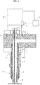
- FIG 1 schematically shows a molding apparatus thus made in which an injector 3, connected to a distributer of molten plastic material distributor or hot runner 2, comprises a nozzle 5 provided - at the free end thereof - with a nozzle terminal 6 placed in communication with the cavity of a mold by means of a gate.
- the flow of the plastic material through the nozzle terminal 6 is controlled by a pin valve 7 axially displaceable along the nozzle 5 by means of an actuator 8, between the lowered fully closing position represented in figure 1 , and a raised maximum opening position.
- the actuator 8 is in this case an electric actuator, and more in particular a rotary electric motor: the arrangement thereof illustrated in figure 1 is solely for indicative purposes, in that it can conveniently be of the type described and illustrated in the aforementioned document n° EP-2679374 , according to which the shaft of rotary electric motor 8 is arranged transversely to the pin valve 7 and actuates it through a transmission (not illustrated) including a nut and screw unit and an oscillating lever. It should be observed that the invention also identically applies to other configurations, for example of the type in which the shaft of the electric motor is axially aligned with the pin valve 7.
- the electric motor 8 is provided - in a known fashion - with an encoder 9 associated to the shaft thereof and suitable to indirectly detect the position of the pin valve 7.
- the encoder 9 is operatively connected to an electronic control unit 4 configured to actuate electric motor 8, and thus the pin valve 7, in a controlled fashion as a function of various parameters.
- the displacement speed of the pin valve 7 carried out by the electric motor 8 is carried out as a function of the position thereof detected by means of the encoder 9.
- the programmable control provides for the discontinuous displacement of the pin valve and the stopping thereof in one or more intermediate positions between the fully closing and maximum opening, and/or vice versa, by setting an always uniform and constant speed during each step for displacing the pin valve in the opening stroke thereof and/or in the closing stroke thereof, unless as otherwise explained hereinafter.
- Such uniform and constant speed combined with the displacement pauses of the pin valve surprisingly allows to improve the aesthetic and structural qualities of the molded articles.
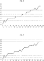
- the diagram of figure 2 shows an example of an opening cycle according to the invention: the upper part of the diagram represents the speed/time correlation and the lower part represents the position/time correlation of the pin valve 7.
- the displacement from the fully closing position to the maximum opening position provides for various steps for stopping the pin valve partial opening intermediate positions, in which the speed thereof is null.
- the displacement speed of the pin valve between each stop position and the subsequent one, except for acceleration-deceleration transients, is always constant and uniform, and this speed can be programmed by means of the electronic control unit 4.
- the diagram of Figure 3 shows an example of a closing cycle according to the invention: also in this case the upper part of the diagram represents the speed/time correlation and the lower part represents the position/time correlation of the pin valve.
- the displacement from the maximum opening position to the fully closing position provides for various steps for stopping the pin valve in partial closing intermediate positions, in which the speed thereof is null.
- the speed of the pin valve between each stop position and the subsequent one is always constant and uniform, and it can also be programmed, i.e. it can be modified whenever deemed necessary, by means of the electronic control unit 4.
- the speed in the sections in which the pin valve is being displaced can constantly be in the order of 20 mm/sec.
- This value same case applying to the number, the position and the duration of the stop steps of the pin valve may vary depending on the programming mode of the electronic control of the actuator of the injector, whether of the electric or fluid type.
- the opening constant and uniform speed may be equal to or different (greater or lesser) from the closing constant and uniform speed.
- the discontinuous displacement, with constant and uniform displacement speed, of the pin valve may be provided for only in one or in the other of the opening and closing cycles.
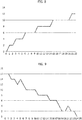
- Figures 4-8 and 9-11 show further alternative examples of speed profiles of the pin valve 7, respectively in opening and closing mode, which fall within the scope of protection of the present invention.
- the abscissas indicate the time in seconds or multiples while the ordinates indicate the position of the pin valve in mm. or multiples.
- this initial speed is a maximum opening speed of the pin valve. Also in this case, the duration of the stop pauses of the pin valve decreases towards the maximum opening position.
- the motion inversion is particularly advantageous should the detection of the position of the pin valve be, like in the case described herein, carried out indirectly by means of the encoder 9 (or equivalent systems), in that this allows to verify and possibly correct the signals regarding the indirect detection of the position of the pin valve 7 transmitted by the encoder 9 of the motor 8 to the electronic control unit 4. In this manner, the precision of the control of the speed of the pin valve becomes considerably more accurate, to the advantage of the quality of the molded articles.
- the duration of the stop pauses of the pin valve is also variable and in the profile of figure 8 such duration extends towards the maximum opening position.
- the same operating modes described above can be provided for in the closing displacement of the pin valve which, besides being discontinuous, has a uniform and constant displacement speed between the stop pauses, whose duration can be equal or different. Also one or more steps for the temporary and brief return to a partial opening position can be contemplated.
- the closing profile represented in figure 9 provides for variable pauses and motion inversion respectively in proximity of the initial maximum open position and the final fully closed position.
- the profiles of figures 10 and 11 on the contrary do not provide for any inversion and the duration of the stops between each displacement section at uniform and constant speed is respectively equal or different, in particular it increases towards the fully closing position.
- the stop times of the pin valve during the closing and/or opening displacement can be conveniently variable according to a mathematical function referred to the internal conditions of the mold: for example, the duration of the stop can be proportional to the injection pressure in the various points of the mold and/or to the flow rate of the injected material.
- the opening and closing profiles of the pin valve can be configured independently from each other. Furthermore, they can have, the one or the other, conventional profiles for example of the constant and continuous speed type.
Landscapes
- Engineering & Computer Science (AREA)
- Manufacturing & Machinery (AREA)
- Mechanical Engineering (AREA)
- Injection Moulding Of Plastics Or The Like (AREA)
- Moulds For Moulding Plastics Or The Like (AREA)
- Processing And Handling Of Plastics And Other Materials For Molding In General (AREA)
Applications Claiming Priority (3)
| Application Number | Priority Date | Filing Date | Title |
|---|---|---|---|
| IT102018000005902A IT201800005902A1 (it) | 2018-05-31 | 2018-05-31 | Procedimento e apparecchiatura di stampaggio ad iniezione di materie plastiche |
| PCT/IB2019/053936 WO2019229564A1 (en) | 2018-05-31 | 2019-05-13 | Process and apparatus for injection molding of plastic materials |
| EP19729847.4A EP3621780B1 (en) | 2018-05-31 | 2019-05-13 | Process and apparatus for injection molding of plastic materials |
Related Parent Applications (2)
| Application Number | Title | Priority Date | Filing Date |
|---|---|---|---|
| EP19729847.4A Division EP3621780B1 (en) | 2018-05-31 | 2019-05-13 | Process and apparatus for injection molding of plastic materials |
| EP19729847.4A Division-Into EP3621780B1 (en) | 2018-05-31 | 2019-05-13 | Process and apparatus for injection molding of plastic materials |
Publications (1)
| Publication Number | Publication Date |
|---|---|
| EP3718734A1 true EP3718734A1 (en) | 2020-10-07 |
Family
ID=63312357
Family Applications (2)
| Application Number | Title | Priority Date | Filing Date |
|---|---|---|---|
| EP19729847.4A Active EP3621780B1 (en) | 2018-05-31 | 2019-05-13 | Process and apparatus for injection molding of plastic materials |
| EP20176644.1A Pending EP3718734A1 (en) | 2018-05-31 | 2019-05-13 | Process and apparatus for injection molding of plastic materials |
Family Applications Before (1)
| Application Number | Title | Priority Date | Filing Date |
|---|---|---|---|
| EP19729847.4A Active EP3621780B1 (en) | 2018-05-31 | 2019-05-13 | Process and apparatus for injection molding of plastic materials |
Country Status (8)
| Country | Link |
|---|---|
| US (2) | US11247373B2 (it) |
| EP (2) | EP3621780B1 (it) |
| JP (2) | JP6836009B2 (it) |
| KR (2) | KR102318506B1 (it) |
| CN (2) | CN110831736B (it) |
| IT (1) | IT201800005902A1 (it) |
| MX (1) | MX2019014793A (it) |
| WO (1) | WO2019229564A1 (it) |
Families Citing this family (2)
| Publication number | Priority date | Publication date | Assignee | Title |
|---|---|---|---|---|
| IT201800005902A1 (it) * | 2018-05-31 | 2018-08-31 | Procedimento e apparecchiatura di stampaggio ad iniezione di materie plastiche | |
| IT202200010004A1 (it) * | 2022-05-13 | 2023-11-13 | Inglass S P A Con Socio Unico | “Apparato per stampaggio a iniezione” |
Citations (8)
| Publication number | Priority date | Publication date | Assignee | Title |
|---|---|---|---|---|
| WO2012074879A1 (en) | 2010-11-23 | 2012-06-07 | Synventive Molding Solutions, Inc. | Injection molding flow control apparatus and method |
| EP2679374A1 (en) | 2012-06-28 | 2014-01-01 | Inglass S.p.A. | Apparatus for injection-moulding of plastic materials |
| US20150266216A1 (en) | 2014-03-18 | 2015-09-24 | Inglass S.P.A. | Method of injection molding of plastic materials |
| WO2016081713A1 (en) * | 2014-11-21 | 2016-05-26 | Synventive Molding Solutions, Inc. | Valve system in an injection molding system |
| US20160167272A1 (en) | 2014-12-11 | 2016-06-16 | Inglass S.P.A. | Method and apparatus for injection molding of plastic materials |
| WO2018020177A1 (fr) * | 2016-07-28 | 2018-02-01 | Runipsys Europe | Système de commande d'un obturateur d'un système d'injection de matière plastique |
| WO2018175362A1 (en) * | 2017-03-20 | 2018-09-27 | Synventive Molding Solutions, Inc. | Valve pin positions and velocity control method and apparatus |
| US20180281258A1 (en) * | 2017-04-04 | 2018-10-04 | Inglass S.P.A. | Method, Apparatus and Press for Injection Moulding of Plastic Material |
Family Cites Families (15)
| Publication number | Priority date | Publication date | Assignee | Title |
|---|---|---|---|---|
| WO1992013700A1 (en) * | 1991-02-12 | 1992-08-20 | Seiki Corporation | Improved hot runner mold arrangement and use thereof |
| JP3154385B2 (ja) * | 1995-05-29 | 2001-04-09 | 宇部興産株式会社 | 射出圧縮成形方法 |
| JP2002178379A (ja) * | 2000-12-15 | 2002-06-26 | Sumitomo Chem Co Ltd | 発泡体の製造装置 |
| JP2006224499A (ja) * | 2005-02-18 | 2006-08-31 | Hirotec Corp | 射出成形機およびその射出成形方法 |
| KR200418312Y1 (ko) * | 2006-03-13 | 2006-06-08 | 김혁중 | 전동 사출성형기 밸브장치 |
| KR100676728B1 (ko) * | 2006-03-13 | 2007-02-01 | 김혁중 | 전동 사출성형기 밸브장치 |
| JP5636800B2 (ja) * | 2010-08-04 | 2014-12-10 | トヨタ車体株式会社 | 射出成形方法および射出成形装置 |
| JP5817077B2 (ja) | 2011-11-17 | 2015-11-18 | 株式会社吉野工業所 | 射出成形方法 |
| CN105050791B (zh) * | 2012-12-13 | 2017-02-15 | 圣万提注塑工业(苏州)有限公司 | 气动驱动销速度控制注射成型装置和方法 |
| JP5878145B2 (ja) * | 2013-08-22 | 2016-03-08 | 日精樹脂工業株式会社 | ホットランナーノズルとこのホットランナーノズルを用いた多層成形品成形用の金型 |
| ITUB20150413A1 (it) * | 2015-05-11 | 2016-11-11 | Inglass Spa | Metodo di gestione di un'apparecchiatura di stampaggio ad iniezione di materie plastiche |
| CN106608027A (zh) * | 2015-10-23 | 2017-05-03 | 柳道(青岛)热流道系统有限公司 | 阀式热流道系统及其注塑工艺 |
| ITUB20156839A1 (it) * | 2015-12-10 | 2017-06-10 | Inglass Spa | Apparecchiatura di stampaggio ad iniezione di materie plastiche |
| JP2017202649A (ja) * | 2016-05-13 | 2017-11-16 | エスバンス 株式会社 | 射出成形金型におけるバルブピンの駆動装置 |
| IT201800005902A1 (it) * | 2018-05-31 | 2018-08-31 | Procedimento e apparecchiatura di stampaggio ad iniezione di materie plastiche |
-
2018
- 2018-05-31 IT IT102018000005902A patent/IT201800005902A1/it unknown
-
2019
- 2019-05-13 CN CN201980003506.9A patent/CN110831736B/zh active Active
- 2019-05-13 KR KR1020217007120A patent/KR102318506B1/ko active IP Right Grant
- 2019-05-13 EP EP19729847.4A patent/EP3621780B1/en active Active
- 2019-05-13 EP EP20176644.1A patent/EP3718734A1/en active Pending
- 2019-05-13 MX MX2019014793A patent/MX2019014793A/es unknown
- 2019-05-13 KR KR1020207002714A patent/KR102252095B1/ko active IP Right Grant
- 2019-05-13 JP JP2020500713A patent/JP6836009B2/ja active Active
- 2019-05-13 US US16/624,934 patent/US11247373B2/en active Active
- 2019-05-13 CN CN202110561996.3A patent/CN113442384B/zh active Active
- 2019-05-13 WO PCT/IB2019/053936 patent/WO2019229564A1/en unknown
-
2021
- 2021-02-04 JP JP2021016754A patent/JP7062106B2/ja active Active
- 2021-11-30 US US17/537,939 patent/US11794392B2/en active Active
Patent Citations (10)
| Publication number | Priority date | Publication date | Assignee | Title |
|---|---|---|---|---|
| WO2012074879A1 (en) | 2010-11-23 | 2012-06-07 | Synventive Molding Solutions, Inc. | Injection molding flow control apparatus and method |
| WO2012087491A1 (en) | 2010-11-23 | 2012-06-28 | Synventive Molding Solutions, Inc. | Injection molding flow control apparatus and method |
| EP2679374A1 (en) | 2012-06-28 | 2014-01-01 | Inglass S.p.A. | Apparatus for injection-moulding of plastic materials |
| US20150266216A1 (en) | 2014-03-18 | 2015-09-24 | Inglass S.P.A. | Method of injection molding of plastic materials |
| US9738016B2 (en) | 2014-03-18 | 2017-08-22 | Inglass S.P.A. | Method of injection molding of plastic materials |
| WO2016081713A1 (en) * | 2014-11-21 | 2016-05-26 | Synventive Molding Solutions, Inc. | Valve system in an injection molding system |
| US20160167272A1 (en) | 2014-12-11 | 2016-06-16 | Inglass S.P.A. | Method and apparatus for injection molding of plastic materials |
| WO2018020177A1 (fr) * | 2016-07-28 | 2018-02-01 | Runipsys Europe | Système de commande d'un obturateur d'un système d'injection de matière plastique |
| WO2018175362A1 (en) * | 2017-03-20 | 2018-09-27 | Synventive Molding Solutions, Inc. | Valve pin positions and velocity control method and apparatus |
| US20180281258A1 (en) * | 2017-04-04 | 2018-10-04 | Inglass S.P.A. | Method, Apparatus and Press for Injection Moulding of Plastic Material |
Non-Patent Citations (1)
| Title |
|---|
| "The new FLEXflow Accurate, stable and easy-to-use Servo-Driven valve gate for top quality. WHAT YOU HAVE ALWAYS DREAMED OF ONLY BETTER", 9 October 2014 (2014-10-09), www.hrsflow.com, XP055205110, Retrieved from the Internet <URL:http://www.hrsflow.com/DownLoadFileUrl.php?url=backend@@download@@file_upload@@allegato@@141009112811_1_flexflow_flyer_eng.pdf&nomefile=1_flexflow_flyer_eng.pdf> [retrieved on 20150728] * |
Also Published As
| Publication number | Publication date |
|---|---|
| IT201800005902A1 (it) | 2018-08-31 |
| US20220088843A1 (en) | 2022-03-24 |
| US11247373B2 (en) | 2022-02-15 |
| MX2019014793A (es) | 2020-08-17 |
| JP2020526419A (ja) | 2020-08-31 |
| BR112019026030A2 (pt) | 2020-11-17 |
| CN110831736A (zh) | 2020-02-21 |
| KR20200023437A (ko) | 2020-03-04 |
| US11794392B2 (en) | 2023-10-24 |
| KR102318506B1 (ko) | 2021-10-28 |
| US20210069954A1 (en) | 2021-03-11 |
| JP2021073120A (ja) | 2021-05-13 |
| CN113442384A (zh) | 2021-09-28 |
| KR102252095B1 (ko) | 2021-05-13 |
| CN113442384B (zh) | 2023-07-21 |
| EP3621780A1 (en) | 2020-03-18 |
| WO2019229564A1 (en) | 2019-12-05 |
| CN110831736B (zh) | 2021-06-08 |
| EP3621780B1 (en) | 2020-07-08 |
| JP6836009B2 (ja) | 2021-02-24 |
| KR20210030495A (ko) | 2021-03-17 |
| JP7062106B2 (ja) | 2022-05-02 |
Similar Documents
| Publication | Publication Date | Title |
|---|---|---|
| US11446850B2 (en) | Method and apparatus for injection molding of plastic materials | |
| US10137622B2 (en) | Method and apparatus for injection molding of plastic materials | |
| US11794392B2 (en) | Process and apparatus for injection molding of plastic materials | |
| US20100225025A1 (en) | Process and device for cascade injection molding | |
| JP6911245B2 (ja) | プラスチック材料の射出成形のための方法、装置、およびプレス | |
| KR102020687B1 (ko) | 사출성형기, 그의 제어장치 및 제어방법 | |
| BR112019026030B1 (pt) | Processo e aparelho para moldagem por injeção de materiais plásticos | |
| JPH0288210A (ja) | プレス成形機のプレス工程制御方法 | |
| JPH02224861A (ja) | 射出成形方法 |
Legal Events
| Date | Code | Title | Description |
|---|---|---|---|
| PUAI | Public reference made under article 153(3) epc to a published international application that has entered the european phase |
Free format text: ORIGINAL CODE: 0009012 |
|
| STAA | Information on the status of an ep patent application or granted ep patent |
Free format text: STATUS: THE APPLICATION HAS BEEN PUBLISHED |
|
| AC | Divisional application: reference to earlier application |
Ref document number: 3621780 Country of ref document: EP Kind code of ref document: P |
|
| AK | Designated contracting states |
Kind code of ref document: A1 Designated state(s): AL AT BE BG CH CY CZ DE DK EE ES FI FR GB GR HR HU IE IS IT LI LT LU LV MC MK MT NL NO PL PT RO RS SE SI SK SM TR |
|
| STAA | Information on the status of an ep patent application or granted ep patent |
Free format text: STATUS: REQUEST FOR EXAMINATION WAS MADE |
|
| 17P | Request for examination filed |
Effective date: 20201125 |
|
| RBV | Designated contracting states (corrected) |
Designated state(s): AL AT BE BG CH CY CZ DE DK EE ES FI FR GB GR HR HU IE IS IT LI LT LU LV MC MK MT NL NO PL PT RO RS SE SI SK SM TR |
|
| STAA | Information on the status of an ep patent application or granted ep patent |
Free format text: STATUS: EXAMINATION IS IN PROGRESS |
|
| 17Q | First examination report despatched |
Effective date: 20210430 |
|
| P01 | Opt-out of the competence of the unified patent court (upc) registered |
Effective date: 20230515 |