EP3715694A2 - Vorrichtung zum verbinden und reparieren von rohrabschnitten eines rohrs, insbesondere eines hdpe rohrs - Google Patents
Vorrichtung zum verbinden und reparieren von rohrabschnitten eines rohrs, insbesondere eines hdpe rohrs Download PDFInfo
- Publication number
- EP3715694A2 EP3715694A2 EP20164776.5A EP20164776A EP3715694A2 EP 3715694 A2 EP3715694 A2 EP 3715694A2 EP 20164776 A EP20164776 A EP 20164776A EP 3715694 A2 EP3715694 A2 EP 3715694A2
- Authority
- EP
- European Patent Office
- Prior art keywords
- pipe
- clamping sleeve
- coupling
- gripping teeth
- coupling rings
- Prior art date
- Legal status (The legal status is an assumption and is not a legal conclusion. Google has not performed a legal analysis and makes no representation as to the accuracy of the status listed.)
- Granted
Links
- 229920001903 high density polyethylene Polymers 0.000 title claims description 8
- 230000008878 coupling Effects 0.000 claims abstract description 111
- 238000010168 coupling process Methods 0.000 claims abstract description 111
- 238000005859 coupling reaction Methods 0.000 claims abstract description 111
- 238000007789 sealing Methods 0.000 claims abstract description 31
- 230000008439 repair process Effects 0.000 claims abstract description 8
- 230000015572 biosynthetic process Effects 0.000 claims abstract description 5
- 239000004700 high-density polyethylene Substances 0.000 claims description 7
- 229920002943 EPDM rubber Polymers 0.000 claims description 4
- 229920000459 Nitrile rubber Polymers 0.000 claims description 4
- XAGFODPZIPBFFR-UHFFFAOYSA-N aluminium Chemical compound [Al] XAGFODPZIPBFFR-UHFFFAOYSA-N 0.000 claims description 2
- 229910052782 aluminium Inorganic materials 0.000 claims description 2
- 238000009749 continuous casting Methods 0.000 claims description 2
- 238000001746 injection moulding Methods 0.000 claims description 2
- 239000004033 plastic Substances 0.000 claims description 2
- 229920003023 plastic Polymers 0.000 claims description 2
- 229910001220 stainless steel Inorganic materials 0.000 claims description 2
- 239000010935 stainless steel Substances 0.000 claims description 2
- 244000089486 Phragmites australis subsp australis Species 0.000 description 4
- 238000010276 construction Methods 0.000 description 2
- 239000007788 liquid Substances 0.000 description 2
- XLYOFNOQVPJJNP-UHFFFAOYSA-N water Substances O XLYOFNOQVPJJNP-UHFFFAOYSA-N 0.000 description 2
- 230000007547 defect Effects 0.000 description 1
- 230000001419 dependent effect Effects 0.000 description 1
- 230000008030 elimination Effects 0.000 description 1
- 238000003379 elimination reaction Methods 0.000 description 1
- 239000012530 fluid Substances 0.000 description 1
- 239000000446 fuel Substances 0.000 description 1
- 239000007789 gas Substances 0.000 description 1
- 238000003466 welding Methods 0.000 description 1
Images

Classifications
-
- F—MECHANICAL ENGINEERING; LIGHTING; HEATING; WEAPONS; BLASTING
- F16—ENGINEERING ELEMENTS AND UNITS; GENERAL MEASURES FOR PRODUCING AND MAINTAINING EFFECTIVE FUNCTIONING OF MACHINES OR INSTALLATIONS; THERMAL INSULATION IN GENERAL
- F16L—PIPES; JOINTS OR FITTINGS FOR PIPES; SUPPORTS FOR PIPES, CABLES OR PROTECTIVE TUBING; MEANS FOR THERMAL INSULATION IN GENERAL
- F16L55/00—Devices or appurtenances for use in, or in connection with, pipes or pipe systems
- F16L55/16—Devices for covering leaks in pipes or hoses, e.g. hose-menders
- F16L55/168—Devices for covering leaks in pipes or hoses, e.g. hose-menders from outside the pipe
- F16L55/17—Devices for covering leaks in pipes or hoses, e.g. hose-menders from outside the pipe by means of rings, bands or sleeves pressed against the outside surface of the pipe or hose
- F16L55/172—Devices for covering leaks in pipes or hoses, e.g. hose-menders from outside the pipe by means of rings, bands or sleeves pressed against the outside surface of the pipe or hose the ring, band or sleeve being tightened by a tangentially arranged threaded pin and a nut
-
- F—MECHANICAL ENGINEERING; LIGHTING; HEATING; WEAPONS; BLASTING
- F16—ENGINEERING ELEMENTS AND UNITS; GENERAL MEASURES FOR PRODUCING AND MAINTAINING EFFECTIVE FUNCTIONING OF MACHINES OR INSTALLATIONS; THERMAL INSULATION IN GENERAL
- F16L—PIPES; JOINTS OR FITTINGS FOR PIPES; SUPPORTS FOR PIPES, CABLES OR PROTECTIVE TUBING; MEANS FOR THERMAL INSULATION IN GENERAL
- F16L21/00—Joints with sleeve or socket
- F16L21/06—Joints with sleeve or socket with a divided sleeve or ring clamping around the pipe-ends
-
- F—MECHANICAL ENGINEERING; LIGHTING; HEATING; WEAPONS; BLASTING
- F16—ENGINEERING ELEMENTS AND UNITS; GENERAL MEASURES FOR PRODUCING AND MAINTAINING EFFECTIVE FUNCTIONING OF MACHINES OR INSTALLATIONS; THERMAL INSULATION IN GENERAL
- F16L—PIPES; JOINTS OR FITTINGS FOR PIPES; SUPPORTS FOR PIPES, CABLES OR PROTECTIVE TUBING; MEANS FOR THERMAL INSULATION IN GENERAL
- F16L21/00—Joints with sleeve or socket
- F16L21/002—Sleeves or nipples for pipes of the same diameter; Reduction pieces
- F16L21/005—Sleeves or nipples for pipes of the same diameter; Reduction pieces made of elastic material, e.g. partly or completely surrounded by clamping devices
-
- F—MECHANICAL ENGINEERING; LIGHTING; HEATING; WEAPONS; BLASTING
- F16—ENGINEERING ELEMENTS AND UNITS; GENERAL MEASURES FOR PRODUCING AND MAINTAINING EFFECTIVE FUNCTIONING OF MACHINES OR INSTALLATIONS; THERMAL INSULATION IN GENERAL
- F16L—PIPES; JOINTS OR FITTINGS FOR PIPES; SUPPORTS FOR PIPES, CABLES OR PROTECTIVE TUBING; MEANS FOR THERMAL INSULATION IN GENERAL
- F16L21/00—Joints with sleeve or socket
- F16L21/06—Joints with sleeve or socket with a divided sleeve or ring clamping around the pipe-ends
- F16L21/065—Joints with sleeve or socket with a divided sleeve or ring clamping around the pipe-ends tightened by tangentially-arranged threaded pins
-
- F—MECHANICAL ENGINEERING; LIGHTING; HEATING; WEAPONS; BLASTING
- F16—ENGINEERING ELEMENTS AND UNITS; GENERAL MEASURES FOR PRODUCING AND MAINTAINING EFFECTIVE FUNCTIONING OF MACHINES OR INSTALLATIONS; THERMAL INSULATION IN GENERAL
- F16L—PIPES; JOINTS OR FITTINGS FOR PIPES; SUPPORTS FOR PIPES, CABLES OR PROTECTIVE TUBING; MEANS FOR THERMAL INSULATION IN GENERAL
- F16L21/00—Joints with sleeve or socket
- F16L21/08—Joints with sleeve or socket with additional locking means
Definitions
- the present invention describes a device for connecting and / or repairing pipe sections of a pipe, in particular an HDPE pipe, according to the preamble of the first claim.
- the device according to the invention relates in particular to a device which on the one hand connects two pipe sections of a pipe or on the other hand repairs a damaged section of a pipe in order to obtain a functional pipe suitable for conveying a liquid.
- Coupling devices in the form of a clamping sleeve for example in the document, are known US 2012/0242083 A1 shown.
- the ones from the US 2012/0242083 A1 known coupling device can be placed around an existing pipeline.
- This known coupling device “Arpol MultiFix” also has several limiting rods that can be connected to the clamping sleeve to achieve axial tensile strength.
- the «Arpol MultiFix» coupling device has the disadvantage, however, that the construction is complicated and handling is difficult.
- the present invention has set itself the task of providing a coupling device for connecting and repairing pipe sections of a pipe, in particular HDPE pipe, which overcomes the disadvantages of the known prior art and in particular has a simplified and compact design.
- a third axial extension of a coupling ring is in a ratio of preferably 1 to 5 to 10, more preferably 2 to 4 to 10, most preferably about 3 to 10, compared to a second axial extension of the clamping sleeve.
- the coupling device according to the invention achieved here has the advantage of a compact and easily manageable construction due to the two relatively small coupling rings, the coupling device according to the invention being easily portable even with larger dimensions.
- the at least two coupling rings arranged on both sides of the clamping sleeve can each be accommodated in a flange bearing with a U-shaped cross-section, so that tensile forces acting on the pipe sections in the installed state are compensated for the formation of an axially tensile repair coupling and so that the tension achieved by the clamping sleeve Sealing area and the axial tensile strength achieved by the coupling rings is spatially separated.
- the coupling device according to the invention advantageously allows a connection of two pipe sections of a pipe that is independent of the weather and can even be carried out under water.
- the coupling device according to the invention is suitable as a tensile, open repair coupling.
- HDPE high density polyethylene
- repairing a pipe can be understood to mean the elimination of defects such as pipe cracks, breaks, punctures and the like.
- connecting pipe sections of a pipe can be understood, among other things, to mean that pipe sections can be laid quickly without welding.
- the coupling device according to the invention advantageously allows the sealing area achieved by the clamping sleeve and the through the coupling rings achieved, axial tensile strength is spatially separated. This results in the further advantage that the gripping teeth are freely movable and have no negative influence on the sealing by the sealing element or sealing sleeve of the clamping sleeve.
- the coupling rings that can be attached on both sides can also be understood as anchor rings.
- an axial tensile strength is understood to mean that the axial mobility of the connected pipe sections is prevented or reduced as far as possible.
- the coupling device according to the invention ensures such an axial tensile strength at a fluid pressure in the pipe of up to 16 bar.
- the coupling device according to the invention already ensures the necessary tightness without attaching additional support rings. Nevertheless, it is optionally conceivable that the coupling device according to the invention has support rings.
- a first axial extension of each flange bearing is preferably in a ratio of preferably 1 to 4 to 10, more preferably 1 to 3 to 10, most preferably about 2 to 10, compared to a second axial extension of the clamping sleeve.
- a flange bearing is understood to mean a bearing element which is designed to receive or support a coupling ring.
- the gripping teeth of the at least two coupling rings are preferably aligned with the clamping sleeve in order to increase the axial tensile strength.
- the gripping teeth are preferably made of aluminum and / or stainless steel and / or a plastic suitable for injection molding and continuous casting.
- the gripping teeth of the at least two coupling rings are preferably interchangeable or, if they are worn, they can be replaced by the gripping teeth having a bore with an internal thread and each being fastened to a coupling ring using a corresponding screw element or riveting.
- an angular distance ⁇ between two adjacent gripping teeth of a coupling ring is preferably between 10 ° to 30 °, more preferably between 15 ° to 25 °, most preferably about 20 ° to 25 ° °.
- the gripping teeth are preferably arranged and designed in such a way that the gripping teeth can engage the pipe up to a maximum of 10%.
- the gripping teeth are arranged in several rows and in particular offset at an angle in the at least two coupling rings, so that a particularly high axial tensile strength is achieved, in particular for high nominal pressures and / or large pipe diameters.
- the sealing element of the coupling device according to the invention is preferably made of ethylene propylene diene rubber (EPDM) and / or nitrile butadiene rubber (NBR).
- EPDM ethylene propylene diene rubber
- NBR nitrile butadiene rubber
- the device is preferably designed in such a way that the closing area of the coupling rings can be offset with respect to the closing area of the clamping sleeve, preferably by 45 ° to 90 °, more preferably by 60 ° to 90 °, very particularly preferably by 90 °, so that greater strength is achieved becomes.
- This displaceability or rotatability has the advantage that, in the event of a torsion of the pipe or the pipeline, the closing areas can also rotate.
- Fig.1a shows a perspective view of a preferred embodiment of the coupling device 1 according to the invention in the assembled or installed state, which provides a connection between the pipe sections R1; R2 of a pipe R, in particular an HDPE pipe, produces.
- the coupling device 1 here comprises a clamping sleeve 5 with an attachable or attached sealing element facing the pipe, which cannot be seen here (see FIG Fig.1b respectively Fig.2a ) as well as with a pipe clamp 9 surrounding the sealing element 10 for producing a sealing connection between the pipe sections R1; R2 of a pipe R.
- Fig.1a here two coupling rings 2 '; 2 "in mechanical operative connection with the clamping sleeve 5 for fastening the coupling device 1 to the pipe R.
- the two coupling rings 2';2" arranged here on both sides of the clamping sleeve 5 are each in one, with one, in particular U-shaped, cross-sectional flange bearings 3 '; 3 "can be received, so that in the installed state, tensile forces acting on the pipe sections R1; R2 are compensated for the formation of an axially tensile repair coupling, and so that the sealing area achieved by the clamping sleeve 5 and that by the Coupling rings 2 '; 2 "achieved, axial tensile strength is spatially separated to prevent a negative influence on the tightness of the sealing element, not shown here.
- the clamping sleeve 5 has two clamping sleeve elements 27 here.
- the coupling device 1 is designed in such a way that the closing area S1 of the two coupling rings 2 '; 2 "can be offset from the closing area S2 of the clamping sleeve 6, preferably by 45 ° to 90 °, more preferably by 60 ° up to 90 °, very particularly preferably 90 °, so that a higher strength is achieved.
- the closing area S1 is formed here by two second fastening bolts 21 which are operatively connected to each other with a second receiving tab 23 '; 23 "and a second bolt element 24';24” which can be received in the second receiving tab 23 '; 23 "(see FIG Fig.2b ).
- the second fastening bolts 21 can have an external thread and the second bolt elements 24 '; 24 "have a bore with a corresponding internal thread, so that a closing movement of a coupling ring 2';2" can be achieved by actuating or rotating the second fastening bolt 21.
- the closing area S2 of the clamping sleeve 6 is formed here by a first first fastening bolt 20 that is operatively connected to a first receiving tab 25 and a first bolt element 26 that can be received in the first receiving tab 25.
- a first bolt element 26 can be received in a first receiving tab 25 and the first bolt elements 26 are provided with two bores with an internal thread, an external thread of the first fastening bolt 20 being designed to correspond to the internal thread of the first bolt elements 26 and by actuation or by rotating the first fastening bolt 20, a closing movement of the clamping sleeve 6 can be achieved.
- a hinge (not shown here) can be provided for the rotatable connection of the clamping sleeve elements 27 of the clamping sleeve 6.
- the coupling device 1 Due to the design of the coupling device 1 with a locking area S1 or S2 provided clamping sleeve 6 or respectively Coupling rings 2 '; 2 ", the coupling device can be placed around an existing pipe for repair purposes.
- Fig.1b shows a perspective view of the coupling device 1 according to the invention in the assembled state without a pipe.
- the flange bearing 3 ′ can be seen to comprise two separate flange bearing elements 30 ′ formed on the pipe clip 9 of the clamping sleeve 5.
- the molded flange bearing elements 30 ' extend at least in sections over the circumference of the clamping sleeve 5.
- Fig.2a shows an in Fig.1a shown cross-section AA through the inventive coupling device 1 in the assembled state, which connects the pipe sections R1; R2 of a pipe R produces.
- clamping sleeve 5 is provided with double sealing lips 11 ′; 11 ′′ arranged at the ends on the sealing element 10 for sealing between the pipe R and the clamping sleeve 5.
- the two coupling rings 2 '; 2 here have a U-shaped cross-section.
- a receiving area A is formed in the U-shaped cross-section of the two coupling rings 2';2", with the at least two coupling rings 2 '; 2 "a plurality of gripping teeth 15 ';15" arranged here in a row are arranged.
- Fig.2a It can be seen that the gripping teeth 15 '; 15 "in the receiving area A of the two coupling rings 2';2” can be received or exchanged in that the gripping teeth 15 '; 15 “comprise a bore B with an internal thread and are here based on a corresponding screw element 16 a coupling ring 2 '; 2 "can be attached.
- Fig.2a also shows that the gripping teeth 15 '; 15 "of the at least two coupling rings 2';2" are oriented towards the clamping sleeve 5 in the installed state of the device 1 to increase the axial tensile strength, with one tooth element Z of the gripping teeth being particularly preferred over one Vertical has an orientation angle ⁇ of preferably 50 ° to 70 °, very particularly preferably about 60 °.
- the gripping teeth 15 '; 15 are arranged in several rows and in particular offset at an angle in the at least two coupling rings 2'; 2" so that a particularly high axial tensile strength is achieved, especially for high nominal pressures and / or large pipe diameters.
- the preferred embodiment of the coupling device 1 according to the invention shown has a third axial extension z of each coupling ring 2 '; 2 "compared to a second axial extension y of the clamping sleeve 5, the third axial extension z of a coupling ring 2';2" being compared to the second axial extension Extension y of the clamping sleeve 5 is in a ratio of preferably 1 to 5 to 10, more preferably 2 to 4 to 10, most preferably about 3 to 10.
- preferred Embodiment of the inventive coupling device 1 has a second axial extension y of each flange bearing 3 '; 3 "of the clamping sleeve 5, the first axial extension x of each flange bearing 3';3" being preferred over a second axial extension y of the clamping sleeve 5 in a ratio of 1 to 4 to 10, more preferably 1 to 3 to 10, most preferably about 2 to 10.
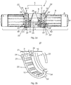
- Fig.2b shows an in Fig.1a shown cross section BB through a coupling ring 2 'of the coupling device 1 according to the invention in the assembled state without a pipe.
- a coupling ring 2 ' can be seen to be formed by two opposing coupling ring sections 22'.
- two opposing closing areas S1 between the two coupling ring sections 22 ' are two opposing closing areas S1 between the two coupling ring sections 22 '.
- the coupling device 1 preferably has an angular distance ⁇ between two adjacent gripping teeth 15 '; 15 "of a coupling ring 2'; 2", preferably between 10 ° to 30 °, more preferably between 15 ° to 25 °, am most preferably about 20 ° to 25 °.
- Fig.2c shows a cross-section through a gripping tooth 15 'of the preferred embodiment of the coupling device according to the invention, the respective tooth elements Z of the gripping teeth 15' having an orientation angle ⁇ of preferably 50 ° to 70 °, very particularly preferably about 60 °, with respect to a vertical.
Landscapes
- Engineering & Computer Science (AREA)
- General Engineering & Computer Science (AREA)
- Mechanical Engineering (AREA)
- Mutual Connection Of Rods And Tubes (AREA)
- Electric Cable Installation (AREA)
- Joints With Pressure Members (AREA)
- Pipe Accessories (AREA)
Abstract
Description
- Die vorliegende Erfindung beschreibt eine Vorrichtung zum Verbinden und / oder Reparieren von Rohrabschnitten eines Rohrs, insbesondere eines HDPE Rohrs, gemäss Oberbegriff des ersten Patentanspruches.
- Die erfindungsgemässe Vorrichtung betrifft insbesondere eine Vorrichtung, welche einerseits zwei Rohrabschnitte eines Rohrs verbindet oder andererseits einen beschädigten Abschnitt eines Rohrs repariert zum Erhalt eines funktionstüchtigen, zum Fördern einer Flüssigkeit geeigneten Rohrs.
- Bekannt sind Kupplungseinrichtungen in Form einer Klemmhülse wie beispielsweise im Dokument
US 2012/0242083 A1 gezeigt. - Die aus der
US 2012/0242083 A1 bekannte Kupplungsvorrichtung kann um eine bestehende Rohrleitung herum gelegt werden. - Bekannte Kupplungsvorrichtungen wie beispielsweise aus der
US 2012/0242083 A1 bekannt haben den Nachteil, dass hohe Temperaturen und hohe Luftfeuchtigkeit problematisch sind beziehungsweise die Handhabung bei hohen Temperaturen und hoher Luftfeuchtigkeit erschwert ist. - Die aus der
US 2012/0242083 A1 bekannte Kupplungsvorrichtung hat den weiteren Nachteil, dass gerade bei höheren Nenndrücken die axiale Zugfestigkeit der Kupplungsvorrichtung zu gering ist. - Im Weiteren ist aus dem Stand der Technik eine solche Kupplungsvorrichtung zum Verbinden und Reparieren von Rohrabschnitten bekannt unter dem Namen «Arpol MultiFix».
- Diese bekannte Kupplungsvorrichtung «Arpol MultiFix» weist zusätzlich mehrere, mit der Klemmhülse verbindbare Begrenzungsstangen zur Erzielung einer axialen Zugfestigkeit auf.
- Die Kupplungsvorrichtung «Arpol MultiFix» hat jedoch den Nachteil, dass Bauweise kompliziert und die Handhabung erschwert ist.
- Die vorliegende Erfindung hat sich zur Aufgabe gestellt, eine Kupplungsvorrichtung zum Verbinden und Reparieren von Rohrabschnitten eines Rohrs, insbesondere HDPE Rohrs, bereitzustellen, welche die Nachteile des bekannten Standes der Technik überwindet und insbesondere eine vereinfachte und kompakte Bauweise aufweist.
- Diese Aufgaben erfüllt eine Vorrichtung mit den Merkmalen des Patentanspruches 1.
- Erfindungsgemäss stehen eine dritte axiale Ausdehnung jeweils eines Kupplungsrings gegenüber einer zweiten axialen Ausdehnung der Klemmhülse in einem Verhältnis von bevorzugt 1 bis 5 zu 10, noch bevorzugter 2 bis 4 zu 10, am meisten bevorzugt etwa 3 zu 10.
- Die hierbei erzielte, erfindungsgemässe Kupplungsvorrichtung hat aufgrund der beiden verhältnismässig klein ausgestalteten Kupplungsringe den Vorteil einer kompakten und leicht handhabbaren Bauweise, wobei die erfindungsgemässe Kupplungsvorrichtung auch bei grösseren Dimensionen leicht tragbar ist.
- Dabei sind die mindestens zwei beidseitig zur Klemmhülse angeordneten Kupplungsringe jeweils in einem, mit einem u-förmigen Querschnitt versehenen Bundlager aufnehmbar, so dass im Einbauzustand auf die Rohrabschnitte wirkende Zugkräfte kompensiert werden zur Ausbildung einer axial-zugfesten Reparaturkupplung und so dass der durch die Klemmhülse erzielte Abdichtungsbereich und die durch die Kupplungsringe erzielte, axiale Zugfestigkeit räumlich getrennt wird.
- Die erfindungsgemässe Kupplungsvorrichtung erlaubt vorteilhaft ein witterungsunabhängiges und sogar unter Wasser durchführbares Verbinden zweier Rohrabschnitte eines Rohrs. Zudem ist die erfindungsgemässe Kupplungsvorrichtung als zugfeste, offene Reparaturkupplung geeignet.
- Im Weiteren wurde vorteilhaft gefunden, dass anhand der erfindungsgemässen Kupplungsvorrichtung eine flexible Verbindung zweier Rohrabschnitte eines Rohrs erzielt werden kann.
- Die Verwendung von High Density Polyethylen (HDPE) für die Rohrabschnitte des Rohrs im Zusammenhang mit der erfindungsgemässen Kupplungsvorrichtung hat den Vorteil, dass ein auf HDPE basierendes Rohr zum Fördern von Flüssigkeiten wie Wasser, Gas, Kraftstoff oder dergleichen besonders geeignet ist.
- Im Sinne der vorliegenden Erfindung kann unter Reparieren eines Rohrs die Beseitigung von Fehlern wie Rohrrisse, Brüche, Einstiche und dergleichen verstanden werden. Im Weiteren kann im Sinne der vorliegenden Erfindung unter Verbinden von Rohrabschnitten eines Rohrs unter anderem verstanden werden, dass ein schnelles Verlegen von Rohrabschnitten ohne ein Schweissen möglich ist.
- Die erfindungsgemässe Kupplungsvorrichtung erlaubt vorteilhaft, dass der durch die Klemmhülse erzielte Abdichtungsbereich und die durch die Kupplungsringe erzielte, axiale Zugfestigkeit räumlich getrennt wird. Hieraus resultiert der weitere Vorteil, dass die Greifzähne freibeweglich sind und keinen negativen Einfluss auf die Abdichtung durch das Dichtelement beziehungsweise Dichtmanschette der Klemmhülse haben.
- Mit anderen Worten können die beidseitig anbringbaren Kupplungsringe auch als Ankerringe aufgefasst.
- Im Sinne der vorliegenden Erfindung wird unter einer axialen Zugfestigkeit verstanden, dass die axiale Beweglichkeit der verbundenen Rohrabschnitte verhindert beziehungsweise möglichst verringert wird.
- Es hat sich vorteilhaft gezeigt, dass die erfindungsgemässe Kupplungsvorrichtung eine solche axiale Zugfestigkeit bei einem Flüssigkeitsdruck im Rohr bis 16bar gewährleistet.
- Zudem hat sich vorteilhaft gezeigt, dass die erfindungsgemässe Kupplungsvorrichtung ohne Anbringung zusätzlicher Stützringe bereits die notwendige Dichtigkeit gewährleistet. Dennoch ist es optional denkbar, dass die erfindungsgemässe Kupplungsvorrichtung Stützringe aufweist.
- Weitere vorteilhafte Ausgestaltungsformen sind in den abhängigen Patentansprüchen angegeben.
- Vorzugsweise stehen bei der erfindungsgemässen Kupplungsvorrichtung eine erste axiale Ausdehnung jeweils eines Bundlagers gegenüber einer zweiten axialen Ausdehnung der Klemmhülse in einem Verhältnis von bevorzugt 1 bis 4 zu 10, noch bevorzugter 1 bis 3 zu 10, am meisten bevorzugt etwa 2 zu 10.
- Im Sinne der vorliegenden Erfindung wird unter einem Bundlager ein Lagerelement verstanden, das die Ausgestaltung geeignet ist zur Aufnahme beziehungsweise Lagerung jeweils eines Kupplungsrings.
- Vorzugsweise sind die Greifzähne der mindestens zwei Kupplungsringe im eingebauten Zustand der Vorrichtung zur Klemmhülse hin ausgerichtet zur Erhöhung der axialen Zugfestigkeit. Hierbei sind die Greifzähne bevorzugt aus Aluminium und / oder aus Edelstahl und / oder einem für Spritzguss und Strangguss geeigneten Kunststoff gefertigt. Im Weiteren sind vorzugsweise die Greifzähne der mindestens zwei Kupplungsringe austauschbar beziehungsweise nach Abnutzung ersetzbar, indem die Greifzähne eine Bohrung mit einem Innengewinde umfassen und anhand eines korrespondierenden Schraubenelements oder mittels Vernieten jeweils an einem Kupplungsring befestigbar sind.
- Vorzugsweise beträgt bei der erfindungsgemässen Kupplungsvorrichtung für einen Innendurchmesser der Kupplungsvorrichtung von <400mm einen Winkelabstand α zwischen zwei benachbarten Greifzähnen jeweils eines Kupplungsrings von bevorzugt zwischen 10° bis 30°, noch bevorzugter zwischen 15° bis 25°, am meisten bevorzugt etwa 20° bis 25°.
- Im Weiteren sind bevorzugt die Greifzähne derart angeordnet und ausgestaltet, so dass die Greifzähne bis zu maximal 10% in das Rohr eingreifen können.
- Gemäss einer weiteren bevorzugten Ausgestaltung der erfindungsgemässen Kupplungsvorrichtung sind die Greifzähne in mehreren Reihen und insbesondere im Winkel versetzt in den mindestens zwei Kupplungsringen angeordnet, so dass eine besonders hohe axiale Zugfestigkeit erreicht wird, insbesondere für hohe Nenndrücke und / oder grosse Rohrdurchmesser.
- Vorzugsweise ist das Dichtungselement der erfindungsgemässen Kupplungsvorrichtung aus Ethylen Propylen Dien Kautschuk (EPDM) und / oder Nitril Butadien Rubber (NBR) gefertigt.
- Bevorzugt ist die Vorrichtung derart ausgestaltet, so dass der Schliessbereich der Kupplungsringe gegenüber dem Schliessbereich der Klemmhülse versetzbar, vorzugsweise um 45° bis 90°, noch bevorzugter um 60° bis 90°, ganz besonders bevorzugt um 90°, so dass eine höhere Festigkeit erzielt wird. Diese Versetzbarkeit beziehungsweise Verdrehbarkeit hat den Vorteil, dass im Falle einer Torsion des Rohrs beziehungsweise der Rohrleitung die Schliessbereiche mitdrehen können.
- Ein bevorzugtes Ausführungsbeispiel des Erfindungsgegenstandes wird nachstehend im Zusammenhang mit den anliegenden Zeichnungen beschrieben. Es zeigen:
- Fig. 1a
- eine perspektivische Ansicht einer bevorzugten Ausführungsform der erfindungsgemässen Kupplungsvorrichtung in eingebauten Zustand, welche eine Verbindung zwischen den Rohrabschnitten eines Rohrs herstellt;
- Fig. 1b
- eine perspektivische Ansicht der bevorzugten Ausführungsform der erfindungsgemässen Kupplungsvorrichtung im zusammengebauten Zustand ohne Rohr;
- Fig. 2a
- einen Querschnitt A-A durch die bevorzugte Ausführungsform der erfindungsgemässe Kupplungsvorrichtung im zusammengebauten Zustand, welche eine Verbindung zwischen den Rohrabschnitten eines Rohrs herstellt;
- Fig. 2b
- einen Querschnitt B-B durch einen Kupplungsring der erfindungsgemässen Kupplungsvorrichtung im zusammengebauten Zustand ohne Rohr;
- Fig. 2c
- einen Querschnitt durch einen Greifzahn der bevorzugten Ausführungsform der erfindungsgemässen Kupplungsvorrichtung.
-
Fig.1a zeigt eine perspektivische Ansicht einer bevorzugten Ausführungsform der erfindungsgemässen Kupplungsvorrichtung 1 im zusammengebauten beziehungsweise eingebauten Zustand, welche eine Verbindung zwischen den Rohrabschnitten R1; R2 eines Rohrs R, insbesondere eines HDPE-Rohrs, herstellt. - Wie in
Fig.1a ersichtlich umfasst die erfindungsgemässe Kupplungsvorrichtung 1 hier eine Klemmhülse 5 mit einem hier nicht ersichtlichen, anbringbaren oder angebrachten, dem Rohr zugewandten Dichtungselement (sieheFig.1b beziehungsweiseFig.2a ) sowie mit einer das Dichtungselement 10 umgebende Rohrschelle 9 zur Herstellung einer dichtenden Verbindung zwischen den Rohrabschnitten R1; R2 eines Rohrs R. Zudem zeigtFig.1a hier zwei, mit der Klemmhülse 5 in mechanischer Wirkverbindung stehende Kupplungsringe 2';2" zum Befestigen der Kupplungsvorrichtung 1 am Rohr R. Dabei sind die hier zwei beidseitig zur Klemmhülse 5 angeordneten Kupplungsringe 2';2" jeweils in einem, mit einem, insbesondere u-förmigen, Querschnitt versehenen Bundlager 3';3" aufnehmbar, so dass im Einbauzustand auf die Rohrabschnitte R1; R2 wirkende Zugkräfte kompensiert werden zur Ausbildung einer axial-zugfesten Reparaturkupplung, und so dass der durch die Klemmhülse 5 erzielte Abdichtungsbereich und die durch die Kupplungsringe 2';2" erzielte, axiale Zugfestigkeit räumlich getrennt wird zur Verhinderung einer negativen Beeinflussung der Dichtigkeit des hier nicht ersichtlichen Dichtungselements. Wie inFig.1a ersichtlich weist hier die Klemmhülse 5 zwei Klemmhülsenelemente 27 auf. - Wie mittels eines Doppelpfeils angedeutet ist die Kupplungsvorrichtung 1 derart ausgestaltet, so dass der Schliessbereich S1 der beiden Kupplungsringe 2';2" gegenüber dem Schliessbereich S2 der Klemmhülse 6 versetzbar ist, vorzugsweise um 45° bis 90°, noch bevorzugter um 60° bis 90°, ganz besonders bevorzugt um 90°, so dass eine höhere Festigkeit erzielt wird.
- Der Schliessbereich S1 wird hier durch zwei zweite, mit jeweils einer zweiten Aufnahmelasche 23';23" sowie einem in der zweiten Aufnahmelasche 23';23" aufnehmbaren, zweiten Bolzenelement 24';24" in Wirkverbindung stehenden, zweiten Befestigungsbolzen 21 gebildet (siehe
Fig.2b ). Hierbei können beispielsweise die zweiten Befestigungsbolzen 21 ein Aussengewinde und die zweiten Bolzenelemente 24';24" eine Bohrung mit einem korrespondierenden Innengewinde aufweisen, so dass durch Betätigung beziehungsweise Drehen des zweiten Befestigungsbolzen 21 eine Schliessbewegung eines Kupplungsrings 2';2" erzielbar ist. - Der Schliessbereich S2 der Klemmhülse 6 wird hier durch eine erste, mit jeweils einer ersten Aufnahmelasche 25 sowie einem in der ersten Aufnahmelasche 25 aufnehmbaren, ersten Bolzenelement 26 in Wirkverbindung stehenden, ersten Befestigungsbolzen 20 gebildet. Wie in
Fig.1a ersichtlich ist hier beispielhaft jeweils in einer ersten Aufnahmelasche 25 ein erstes Bolzenelement 26 aufnehmbar und die ersten Bolzenelemente 26 mit zwei Bohrungen mit einem Innengewinde versehen, wobei hier ein Aussengewinde der ersten Befestigungsbolzens 20 mit dem Innengewinde der ersten Bolzenelemente 26 korrespondierend ausgebildet ist und dabei durch Betätigung beziehungsweise Drehen des ersten Befestigungsbolzens 20 eine Schliessbewegung der Klemmhülse 6 erzielbar ist. Auf der dem Schliessbereich S2 gegenüberliegenden Seite kann ein hier nicht gezeigtes Scharnier vorgesehen sein zur drehbaren Verbindung der Klemmhülsenelemente 27 der Klemmhülse 6. - Aufgrund der Ausgestaltung der Kupplungsvorrichtung 1 mit einem Schliessbereich S1 beziehungsweise S2 versehenen Klemmhülse 6 beziehungsweise Kupplungsringe 2';2" kann die Kupplungsvorrichtung für Reparaturzwecke um ein bestehendes Rohr herumgelegt werden.
-
Fig.1b zeigt eine perspektivische Ansicht der erfindungsgemässen Kupplungsvorrichtung 1 im zusammengebauten Zustand ohne Rohr. - Wie in
Fig.1b ersichtlich umfasst hier das Bundlager 3' zwei getrennte, an die Rohrschelle 9 der Klemmhülse 5 angeformte Bundlagerelemente 30'. Dabei erstrecken sich die angeformten Bundlagerelemente 30' zumindest abschnittsweise über den Umfang der Klemmhülse 5. Eine derartige Ausgestaltung des Bundlagers 3' erlaubt die erwähnte Versetzbarkeit der Schliessbereiche S1 und S2. -
Fig.2a zeigt einen inFig.1a angezeigten Querschnitt A-A durch die erfindungsgemässe Kupplungsvorrichtung 1 im zusammengebauten Zustand, welche eine Verbindung zwischen den Rohrabschnitten R1; R2 eines Rohrs R herstellt. - Dabei ist hier die Klemmhülse 5 jeweils mit am Dichtungselement 10 endseitig angeordneten, doppelten Dichtlippen 11';11" zur Abdichtung zwischen Rohr R und Klemmhülse 5 versehen.
- Wie in
Fig.2a ersichtlich weisen die zwei Kupplungsringe 2';2" hier einen u-förmigen Querschnitt auf. Dabei wird hier im u-förmigen Querschnitt der beiden Kupplungsringe 2';2" ein Aufnahmebereich A gebildet, wobei im Aufnahmebereich A der mindestens zwei Kupplungsringe 2';2" eine Vielzahl von hier in einer Reihe angeordneten Greifzähnen 15';15" angeordnet sind. Insbesondere ist hierbei inFig.2a ersichtlich, dass die Greifzähne 15';15" im Aufnahmebereich A der beiden Kupplungsringe 2';2" aufnehmbar beziehungsweise austauschbar sind, indem die Greifzähne 15';15" eine Bohrung B mit einem Innengewinde umfassen und hier anhand eines korrespondierenden Schraubenelements 16 jeweils an einem Kupplungsring 2';2" befestigbar sind.Fig.2a zeigt zudem, dass die Greifzähne 15';15" der mindestens zwei Kupplungsringe 2';2" im eingebauten Zustand der Vorrichtung 1 zur Klemmhülse 5 hin ausgerichtet sind zur Erhöhung der axialen Zugfestigkeit, wobei ganz besonders bevorzugt jeweils ein Zahnelement Z der Greifzähne gegenüber einer Vertikale einen Ausrichtungswinkel β von bevorzugt 50° bis 70°, ganz besonders bevorzugt etwa 60° aufweist. - Alternativ ist es denkbar, dass gemäss einer weiteren, bevorzugten Ausführungsform die Greifzähne 15';15" in mehreren Reihen und insbesondere im Winkel versetzt in den mindestens zwei Kupplungsringen 2';2" angeordnet sind, so dass eine besonders hohe axiale Zugfestigkeit erreicht wird, insbesondere für hohe Nenndrücke und / oder grosse Rohrdurchmesser.
- Wie in
Fig.2a ersichtlich sind hier zwei beidseitig zur Klemmhülse 5 angeordnete Kupplungsringe 2';2" jeweils in einem, mit einem hier u-förmigen, Querschnitt versehenen Bundlager 3';3" aufgenommen, so dass im Einbauzustand auf die Rohrabschnitte R1; R2 wirkende Zugkräfte kompensiert werden zur Ausbildung einer axial-zugfesten Reparaturkupplung. Dadurch wird vorteilhaft der durch die Klemmhülse 5 erzielte Abdichtungsbereich und die durch die Kupplungsringe 2';2" erzielte, axiale Zugfestigkeit räumlich getrennt zur Verhinderung einer negativen Beeinflussung der Dichtigkeit des Dichtungselements 10. - Die in
Fig.2a gezeigte, bevorzugte Ausführungsform der erfindungsgemässen Kupplungsvorrichtung 1 weist eine dritte axiale Ausdehnung z jeweils eines Kupplungsrings 2';2" gegenüber einer zweiten axialen Ausdehnung y der Klemmhülse 5, wobei die dritte axiale Ausdehnung z jeweils eines Kupplungsrings 2';2" gegenüber der zweiten axialen Ausdehnung y der Klemmhülse 5 in einem Verhältnis von bevorzugt 1 bis 5 zu 10, noch bevorzugter 2 bis 4 zu 10, am meisten bevorzugt etwa 3 zu 10 stehen. Im Weiteren weist die inFig.2a gezeigte, bevorzugte Ausführungsform der erfindungsgemässen Kupplungsvorrichtung 1 eine zweite axiale Ausdehnung y jeweils eines Bundlagers 3';3" der Klemmhülse 5, wobei die erste axiale Ausdehnung x jeweils eines Bundlagers 3';3" gegenüber einer zweiten axialen Ausdehnung y der Klemmhülse 5 in einem Verhältnis von bevorzugt 1 bis 4 zu 10, noch bevorzugter 1 bis 3 zu 10, am meisten bevorzugt etwa 2 zu 10 stehen. -
Fig.2b zeigt einen inFig.1a angezeigten Querschnitt B-B durch einen Kupplungsring 2' der erfindungsgemässen Kupplungsvorrichtung 1 im zusammengebauten Zustand ohne Rohr. - Wie in
Fig.2b ersichtlich wird ein Kupplungsring 2' durch zwei gegenüberliegende Kupplungsringabschnitte 22' gebildet. Wie zudem inFig.2b gezeigt liegen zwischen den beiden Kupplungsringabschnitten 22' jeweils zwei gegenüberliegende Schliessbereiche S1. - Bevorzugt weist die Kupplungsvorrichtung 1 bei einem Innendurchmesser DI von <400mm einen Winkelabstand α zwischen zwei benachbarten Greifzähnen 15';15" jeweils eines Kupplungsrings 2';2" bevorzugt zwischen 10° bis 30°, noch bevorzugter zwischen 15° bis 25°, am meisten bevorzugt etwa 20° bis 25° auf.
-
Fig.2c zeigt einen Querschnitt durch einen Greifzahn 15' der bevorzugten Ausführungsform der erfindungsgemässen Kupplungsvorrichtung, wobei die jeweiligen Zahnelemente Z der Greifzähne 15' gegenüber einer Vertikale einen Ausrichtungswinkel β von bevorzugt 50° bis 70°, ganz besonders bevorzugt etwa 60° aufweisen. -
- 1 Vorrichtung / Kupplungsvorrichtung
- 2';2" Kupplungsringe
- 3';3" Bundlager
- 5 Klemmhülse
- 9 Rohrschelle
- 10 Dichtungselement
- 11';11" Dichtungslippe
- 15'; 15" Greifzahn
- 16 Schraubenelement (zur Befestigung eines Greifzahns)
- 20 Erste Befestigungsbolzen (an der Klemmhülse)
- 21 Zweite Befestigungsbolzen (an den Kupplungsringen)
- 22';22" Kupplungsringabschnitte
- 23';23" Zweite Aufnahmelasche (an den Kupplungsringen)
- 24';24" Zweites Bolzenelement (zur Aufnahme in der Aufnahmelasche eines Kupplungsrings)
- 25 Erste Aufnahmelasche (an der Klemmhülse)
- 26 Erstes Bolzenelement (an der Klemmhülse)
- 27 Klemmhülsenelement
- 30';30" Bundlagerabschnitte
- A Aufnahmebereich (der Kupplungsringe)
- B Bohrung (in Greifzahn)
- DI Innendurchmesser (der Vorrichtung)
- Z Zahnelemente (eines Greifzahns)
- α Winkelabstand (zwischen benachbarten Greifzähnen)
- β Winkelausrichtung (der Zähne eines Greifzahns)
Claims (10)
- Vorrichtung (1) zum Verbinden und Reparieren von Rohrabschnitten (R1; R2) eines Rohrs (R), insbesondere HDPE Rohrs, umfassend:- mindestens eine Klemmhülse (5) umfassend ein anbringbares Dichtungselement (10) und eine das Dichtungselement (10) umgebende Rohrschelle (9) zur Herstellung der Verbindung zwischen den Rohrabschnitten (R1; R2) eines Rohrs (R);
wobei die mindestens eine Klemmhülse (5) jeweils mit, vorzugsweise am Dichtungselement (10) endseitig angeordneten und, vorzugsweise doppelten, Dichtlippen (11'; 11 ") zur Abdichtung zwischen Rohr (R) und Klemmhülse (5) versehen ist;- mindestens zwei, mit der Klemmhülse (5) in mechanischer Wirkverbindung stehende Kupplungsringe (2';2") zum Befestigen der Kupplungsvorrichtung (1) am Rohr (R);wobei die mindestens zwei Kupplungsringe (2';2") einen u-, m- oder v-förmigen Querschnitt aufweisen;
wobei in einem Aufnahmebereich (A) der mindestens zwei Kupplungsringe (2';2") eine Vielzahl von bevorzugt in mindestens einer Reihe angeordneten Greifzähnen (15';15") angeordnet sind; und wobei die mindestens zwei beidseitig zur Klemmhülse (5) angeordneten Kupplungsringe (2';2") jeweils in einem, mit einem, insbesondere u-förmigen, Querschnitt versehenen Bundlager (3';3") aufnehmbar sind, so dass im Einbauzustand auf die Rohrabschnitte (R1; R2) wirkende Zugkräfte kompensiert werden zur Ausbildung einer axial-zugfesten Reparaturkupplung, und so dass der durch die Klemmhülse (5) erzielte Abdichtungsbereich und die durch die Kupplungsringe (2';2") erzielte, axiale Zugfestigkeit räumlich getrennt wird zur Verhinderung einer negativen Beeinflussung der Dichtigkeit des Dichtungselements (10);
dadurch gekennzeichnet, dass
eine dritte axiale Ausdehnung (z) jeweils eines Kupplungsrings (2';2") gegenüber einer zweiten axialen Ausdehnung (y) der Klemmhülse (5) in einem Verhältnis von bevorzugt 1 bis 5 zu 10, noch bevorzugter 2 bis 4 zu 10, am meisten bevorzugt etwa 3 zu 10 stehen. - Vorrichtung (1) nach Patentanspruch 1,
dadurch gekennzeichnet, dass
eine erste axiale Ausdehnung (x) jeweils eines Bundlagers (3';3") gegenüber einer zweiten axialen Ausdehnung (y) der Klemmhülse (5) in einem Verhältnis von bevorzugt 1 bis 4 zu 10, noch bevorzugter 1 bis 3 zu 10, am meisten bevorzugt etwa 2 zu 10 stehen. - Vorrichtung (1) nach Patentanspruch 1 oder 2,
dadurch gekennzeichnet, dass
die Greifzähne (15';15") der mindestens zwei Kupplungsringe (2';2") im eingebauten Zustand der Vorrichtung (1) zur Klemmhülse (5) hin ausgerichtet sind zur Erhöhung der axialen Zugfestigkeit. - Vorrichtung (1) nach einem der vorherigen Patentansprüche,
dadurch gekennzeichnet, dass
die Greifzähne (15';15") aus Aluminium und / oder aus Edelstahl und / oder einem für Spritzguss und Strangguss geeigneten Kunststoff gefertigt sind. - Vorrichtung (1) nach einem der vorherigen Patentansprüche,
dadurch gekennzeichnet, dass
die Greifzähne (15';15") der mindestens zwei Kupplungsringe (2';2") austauschbar sind, indem die Greifzähne (15';15") eine Bohrung (B) mit einem Innengewinde umfassen und anhand eines korrespondierenden Schraubenelements (16) oder mittels Vernieten jeweils an einem Kupplungsring (2';2") befestigbar sind. - Vorrichtung (1) nach einem der vorherigen Patentansprüche,
dadurch gekennzeichnet, dass
insbesondere für einen Innendurchmesser (DI) der Vorrichtung von <400mm, ein Winkelabstand (a) zwischen zwei benachbarten Greifzähnen (15';15") jeweils eines Kupplungsrings (2';2") bevorzugt zwischen 10° bis 30°, noch bevorzugter zwischen 15° bis 25°, am meisten bevorzugt etwa 20° bis 25° beträgt. - Vorrichtung (1) nach einem der vorherigen Patentansprüche,
dadurch gekennzeichnet, dass
die Greifzähne (15';15") derart angeordnet und ausgestaltet sind, so dass die Greifzähne (15';15") bis zu maximal 10% in das Rohr (R) eingreifen können. - Vorrichtung (1) nach einem der vorherigen Patentansprüche,
dadurch gekennzeichnet, dass
die Greifzähne (15';15") in mehreren Reihen und insbesondere im Winkel versetzt in den mindestens zwei Kupplungsringen (2';2") angeordnet sind, so dass eine besonders hohe axiale Zugfestigkeit erreicht wird, insbesondere für hohe Nenndrücke und / oder grosse Rohrdurchmesser. - Vorrichtung (1) nach einem der vorherigen Patentansprüche,
dadurch gekennzeichnet, dass
das Dichtungselement (10) aus Ethylen Propylen Dien Kautschuk (EPDM) und / oder Nitril Butadien Rubber (NBR) gefertigt ist. - Vorrichtung (1) nach einem der vorherigen Patentansprüche,
dadurch gekennzeichnet, dass
die Vorrichtung derart ausgestaltet ist, so dass der Schliessbereich (S1) der Kupplungsringe (2';2") gegenüber Schliessbereich (S2) der Klemmhülse (6) versetzbar ist, vorzugsweise um 45° bis 90°, noch bevorzugter um 60° bis 90°, ganz besonders bevorzugt um 90°, so dass eine höhere Festigkeit erzielt wird.
Applications Claiming Priority (1)
| Application Number | Priority Date | Filing Date | Title |
|---|---|---|---|
| CH00392/19A CH716001A2 (de) | 2019-03-26 | 2019-03-26 | Vorrichtung zum Verbinden und Reparieren von Rohrabschnitten eines Rohrs, insbesondere eines HDPE Rohrs. |
Publications (3)
| Publication Number | Publication Date |
|---|---|
| EP3715694A2 true EP3715694A2 (de) | 2020-09-30 |
| EP3715694A3 EP3715694A3 (de) | 2020-11-11 |
| EP3715694B1 EP3715694B1 (de) | 2022-05-04 |
Family
ID=69953815
Family Applications (1)
| Application Number | Title | Priority Date | Filing Date |
|---|---|---|---|
| EP20164776.5A Active EP3715694B1 (de) | 2019-03-26 | 2020-03-23 | Vorrichtung zum verbinden und reparieren von rohrabschnitten eines rohrs, insbesondere eines hdpe rohrs |
Country Status (4)
| Country | Link |
|---|---|
| EP (1) | EP3715694B1 (de) |
| CH (1) | CH716001A2 (de) |
| ES (1) | ES2924385T3 (de) |
| MA (1) | MA53296A (de) |
Citations (1)
| Publication number | Priority date | Publication date | Assignee | Title |
|---|---|---|---|---|
| US20120242083A1 (en) | 2011-03-22 | 2012-09-27 | Airvac Inc | Pipe coupling |
Family Cites Families (1)
| Publication number | Priority date | Publication date | Assignee | Title |
|---|---|---|---|---|
| US7665773B2 (en) * | 2006-06-21 | 2010-02-23 | Conocophillips Company | Self-tightening clamp assemblies for protection against full pipe separation |
-
2019
- 2019-03-26 CH CH00392/19A patent/CH716001A2/de unknown
-
2020
- 2020-03-23 EP EP20164776.5A patent/EP3715694B1/de active Active
- 2020-03-23 MA MA053296A patent/MA53296A/fr unknown
- 2020-03-23 ES ES20164776T patent/ES2924385T3/es active Active
Patent Citations (1)
| Publication number | Priority date | Publication date | Assignee | Title |
|---|---|---|---|---|
| US20120242083A1 (en) | 2011-03-22 | 2012-09-27 | Airvac Inc | Pipe coupling |
Also Published As
| Publication number | Publication date |
|---|---|
| EP3715694B1 (de) | 2022-05-04 |
| ES2924385T3 (es) | 2022-10-06 |
| CH716001A2 (de) | 2020-09-30 |
| EP3715694A3 (de) | 2020-11-11 |
| MA53296A (fr) | 2022-02-16 |
Similar Documents
| Publication | Publication Date | Title |
|---|---|---|
| DE602005002368T2 (de) | Anordnung zur Verbindung eines Kraftstoffspeichers für Kraftstoff unter Druck und mindestens einem Injektor, für eine Brennkraftmaschine | |
| EP2492569A2 (de) | Muffenverbindung | |
| DE2104702A1 (de) | Rohrkupplung | |
| CH643341A5 (de) | Flanschverbindung. | |
| DE3838935A1 (de) | Kupplungsstueck | |
| EP2904301B1 (de) | Halteriegel für eine muffenrohrverbindung | |
| DE102014205626A1 (de) | Dichtungsvorrichtung | |
| EP3715694B1 (de) | Vorrichtung zum verbinden und reparieren von rohrabschnitten eines rohrs, insbesondere eines hdpe rohrs | |
| EP2053298B1 (de) | Verteileranordnung | |
| DE102019002736A1 (de) | Verwendung einer Manschette zum Verbinden von Leitungen, Verfahren zum Verbinden von Leitungen eines Wärmetauschermoduls und Wärmetauschersystem mit der entsprechenden Verbindung | |
| DE202016106901U1 (de) | Rohrverbinder | |
| EP2607786A1 (de) | Rohrbogen zur Abgasführung in Heizungsanlagen und Anordnung mit einem Rohrbogen | |
| DE10222559B4 (de) | Rohrkompensatoranordnung zur Aufnahme von bei Erwärmung oder Abkühlung eines Leitungsrohrs auftretenden axialen und lateralen Bewegungen | |
| DE2911448A1 (de) | Rohrverbindung | |
| DE202011102671U1 (de) | Vorrichtung zum Abdichten von Ringräumen | |
| DE102004018229B3 (de) | Fluidverteilvorrichtung | |
| DE202012003173U1 (de) | Formteil mit mindestens einer Steckmuffe aus Kunststoff sowie mit einer ringförmigen Lippendichtung und Rohrverbindungsanordnung mit einem solchen Formteil | |
| DE60216093T2 (de) | Rohrverbindung | |
| DE4037279C2 (de) | Kompensator | |
| DE2937193A1 (de) | Rohrverbindungsvorrichtung | |
| DE202022102378U1 (de) | Klemmverschraubung, Verwendung einer Klemmverschraubung und eine Schlauchanordnung | |
| DE2324910A1 (de) | Loesbare anschlussverbindung fuer eine z. b. aus metall bestehende starre leitung | |
| DE3232221A1 (de) | Verbindung eines kunststoffummantelten stahlrohres mit einem kunststoffrohr | |
| DE102022110730A1 (de) | Klemmverschraubung, Verwendung einer Klemmverschraubung und eine Schlauchanordnung | |
| EP0987481B1 (de) | Pressringdichtung |
Legal Events
| Date | Code | Title | Description |
|---|---|---|---|
| PUAI | Public reference made under article 153(3) epc to a published international application that has entered the european phase |
Free format text: ORIGINAL CODE: 0009012 |
|
| STAA | Information on the status of an ep patent application or granted ep patent |
Free format text: STATUS: THE APPLICATION HAS BEEN PUBLISHED |
|
| AK | Designated contracting states |
Kind code of ref document: A2 Designated state(s): AL AT BE BG CH CY CZ DE DK EE ES FI FR GB GR HR HU IE IS IT LI LT LU LV MC MK MT NL NO PL PT RO RS SE SI SK SM TR |
|
| AX | Request for extension of the european patent |
Extension state: BA ME |
|
| PUAL | Search report despatched |
Free format text: ORIGINAL CODE: 0009013 |
|
| AK | Designated contracting states |
Kind code of ref document: A3 Designated state(s): AL AT BE BG CH CY CZ DE DK EE ES FI FR GB GR HR HU IE IS IT LI LT LU LV MC MK MT NL NO PL PT RO RS SE SI SK SM TR |
|
| AX | Request for extension of the european patent |
Extension state: BA ME |
|
| RIC1 | Information provided on ipc code assigned before grant |
Ipc: F16L 21/06 20060101ALI20201008BHEP Ipc: F16L 21/08 20060101ALI20201008BHEP Ipc: F16L 55/172 20060101AFI20201008BHEP |
|
| STAA | Information on the status of an ep patent application or granted ep patent |
Free format text: STATUS: REQUEST FOR EXAMINATION WAS MADE |
|
| 17P | Request for examination filed |
Effective date: 20210507 |
|
| RAV | Requested validation state of the european patent: fee paid |
Extension state: MA Effective date: 20210507 Extension state: TN Effective date: 20210507 |
|
| RBV | Designated contracting states (corrected) |
Designated state(s): AL AT BE BG CH CY CZ DE DK EE ES FI FR GB GR HR HU IE IS IT LI LT LU LV MC MK MT NL NO PL PT RO RS SE SI SK SM TR |
|
| RIC1 | Information provided on ipc code assigned before grant |
Ipc: F16L 21/08 20060101ALI20210826BHEP Ipc: F16L 21/06 20060101ALI20210826BHEP Ipc: F16L 55/172 20060101AFI20210826BHEP |
|
| GRAP | Despatch of communication of intention to grant a patent |
Free format text: ORIGINAL CODE: EPIDOSNIGR1 |
|
| STAA | Information on the status of an ep patent application or granted ep patent |
Free format text: STATUS: GRANT OF PATENT IS INTENDED |
|
| GRAJ | Information related to disapproval of communication of intention to grant by the applicant or resumption of examination proceedings by the epo deleted |
Free format text: ORIGINAL CODE: EPIDOSDIGR1 |
|
| GRAP | Despatch of communication of intention to grant a patent |
Free format text: ORIGINAL CODE: EPIDOSNIGR1 |
|
| INTG | Intention to grant announced |
Effective date: 20211012 |
|
| INTG | Intention to grant announced |
Effective date: 20211104 |
|
| GRAS | Grant fee paid |
Free format text: ORIGINAL CODE: EPIDOSNIGR3 |
|
| GRAA | (expected) grant |
Free format text: ORIGINAL CODE: 0009210 |
|
| STAA | Information on the status of an ep patent application or granted ep patent |
Free format text: STATUS: THE PATENT HAS BEEN GRANTED |
|
| AK | Designated contracting states |
Kind code of ref document: B1 Designated state(s): AL AT BE BG CH CY CZ DE DK EE ES FI FR GB GR HR HU IE IS IT LI LT LU LV MC MK MT NL NO PL PT RO RS SE SI SK SM TR |
|
| REG | Reference to a national code |
Ref country code: GB Ref legal event code: FG4D Free format text: NOT ENGLISH |
|
| REG | Reference to a national code |
Ref country code: CH Ref legal event code: EP |
|
| REG | Reference to a national code |
Ref country code: AT Ref legal event code: REF Ref document number: 1489389 Country of ref document: AT Kind code of ref document: T Effective date: 20220515 |
|
| REG | Reference to a national code |
Ref country code: DE Ref legal event code: R096 Ref document number: 502020001036 Country of ref document: DE |
|
| REG | Reference to a national code |
Ref country code: IE Ref legal event code: FG4D Free format text: LANGUAGE OF EP DOCUMENT: GERMAN |
|
| REG | Reference to a national code |
Ref country code: SE Ref legal event code: TRGR |
|
| REG | Reference to a national code |
Ref country code: LT Ref legal event code: MG9D |
|
| RAP4 | Party data changed (patent owner data changed or rights of a patent transferred) |
Owner name: ABORRA AG |
|
| REG | Reference to a national code |
Ref country code: NL Ref legal event code: MP Effective date: 20220504 |
|
| REG | Reference to a national code |
Ref country code: ES Ref legal event code: FG2A Ref document number: 2924385 Country of ref document: ES Kind code of ref document: T3 Effective date: 20221006 |
|
| PG25 | Lapsed in a contracting state [announced via postgrant information from national office to epo] |
Ref country code: PT Free format text: LAPSE BECAUSE OF FAILURE TO SUBMIT A TRANSLATION OF THE DESCRIPTION OR TO PAY THE FEE WITHIN THE PRESCRIBED TIME-LIMIT Effective date: 20220905 Ref country code: NO Free format text: LAPSE BECAUSE OF FAILURE TO SUBMIT A TRANSLATION OF THE DESCRIPTION OR TO PAY THE FEE WITHIN THE PRESCRIBED TIME-LIMIT Effective date: 20220804 Ref country code: NL Free format text: LAPSE BECAUSE OF FAILURE TO SUBMIT A TRANSLATION OF THE DESCRIPTION OR TO PAY THE FEE WITHIN THE PRESCRIBED TIME-LIMIT Effective date: 20220504 Ref country code: LT Free format text: LAPSE BECAUSE OF FAILURE TO SUBMIT A TRANSLATION OF THE DESCRIPTION OR TO PAY THE FEE WITHIN THE PRESCRIBED TIME-LIMIT Effective date: 20220504 Ref country code: HR Free format text: LAPSE BECAUSE OF FAILURE TO SUBMIT A TRANSLATION OF THE DESCRIPTION OR TO PAY THE FEE WITHIN THE PRESCRIBED TIME-LIMIT Effective date: 20220504 Ref country code: GR Free format text: LAPSE BECAUSE OF FAILURE TO SUBMIT A TRANSLATION OF THE DESCRIPTION OR TO PAY THE FEE WITHIN THE PRESCRIBED TIME-LIMIT Effective date: 20220805 Ref country code: FI Free format text: LAPSE BECAUSE OF FAILURE TO SUBMIT A TRANSLATION OF THE DESCRIPTION OR TO PAY THE FEE WITHIN THE PRESCRIBED TIME-LIMIT Effective date: 20220504 Ref country code: BG Free format text: LAPSE BECAUSE OF FAILURE TO SUBMIT A TRANSLATION OF THE DESCRIPTION OR TO PAY THE FEE WITHIN THE PRESCRIBED TIME-LIMIT Effective date: 20220804 |
|
| PG25 | Lapsed in a contracting state [announced via postgrant information from national office to epo] |
Ref country code: RS Free format text: LAPSE BECAUSE OF FAILURE TO SUBMIT A TRANSLATION OF THE DESCRIPTION OR TO PAY THE FEE WITHIN THE PRESCRIBED TIME-LIMIT Effective date: 20220504 Ref country code: PL Free format text: LAPSE BECAUSE OF FAILURE TO SUBMIT A TRANSLATION OF THE DESCRIPTION OR TO PAY THE FEE WITHIN THE PRESCRIBED TIME-LIMIT Effective date: 20220504 Ref country code: LV Free format text: LAPSE BECAUSE OF FAILURE TO SUBMIT A TRANSLATION OF THE DESCRIPTION OR TO PAY THE FEE WITHIN THE PRESCRIBED TIME-LIMIT Effective date: 20220504 Ref country code: IS Free format text: LAPSE BECAUSE OF FAILURE TO SUBMIT A TRANSLATION OF THE DESCRIPTION OR TO PAY THE FEE WITHIN THE PRESCRIBED TIME-LIMIT Effective date: 20220904 |
|
| PG25 | Lapsed in a contracting state [announced via postgrant information from national office to epo] |
Ref country code: SM Free format text: LAPSE BECAUSE OF FAILURE TO SUBMIT A TRANSLATION OF THE DESCRIPTION OR TO PAY THE FEE WITHIN THE PRESCRIBED TIME-LIMIT Effective date: 20220504 Ref country code: SK Free format text: LAPSE BECAUSE OF FAILURE TO SUBMIT A TRANSLATION OF THE DESCRIPTION OR TO PAY THE FEE WITHIN THE PRESCRIBED TIME-LIMIT Effective date: 20220504 Ref country code: RO Free format text: LAPSE BECAUSE OF FAILURE TO SUBMIT A TRANSLATION OF THE DESCRIPTION OR TO PAY THE FEE WITHIN THE PRESCRIBED TIME-LIMIT Effective date: 20220504 Ref country code: EE Free format text: LAPSE BECAUSE OF FAILURE TO SUBMIT A TRANSLATION OF THE DESCRIPTION OR TO PAY THE FEE WITHIN THE PRESCRIBED TIME-LIMIT Effective date: 20220504 Ref country code: DK Free format text: LAPSE BECAUSE OF FAILURE TO SUBMIT A TRANSLATION OF THE DESCRIPTION OR TO PAY THE FEE WITHIN THE PRESCRIBED TIME-LIMIT Effective date: 20220504 Ref country code: CZ Free format text: LAPSE BECAUSE OF FAILURE TO SUBMIT A TRANSLATION OF THE DESCRIPTION OR TO PAY THE FEE WITHIN THE PRESCRIBED TIME-LIMIT Effective date: 20220504 |
|
| REG | Reference to a national code |
Ref country code: DE Ref legal event code: R097 Ref document number: 502020001036 Country of ref document: DE |
|
| PLBE | No opposition filed within time limit |
Free format text: ORIGINAL CODE: 0009261 |
|
| STAA | Information on the status of an ep patent application or granted ep patent |
Free format text: STATUS: NO OPPOSITION FILED WITHIN TIME LIMIT |
|
| PG25 | Lapsed in a contracting state [announced via postgrant information from national office to epo] |
Ref country code: AL Free format text: LAPSE BECAUSE OF FAILURE TO SUBMIT A TRANSLATION OF THE DESCRIPTION OR TO PAY THE FEE WITHIN THE PRESCRIBED TIME-LIMIT Effective date: 20220504 |
|
| 26N | No opposition filed |
Effective date: 20230207 |
|
| PGFP | Annual fee paid to national office [announced via postgrant information from national office to epo] |
Ref country code: FR Payment date: 20230328 Year of fee payment: 4 |
|
| PG25 | Lapsed in a contracting state [announced via postgrant information from national office to epo] |
Ref country code: SI Free format text: LAPSE BECAUSE OF FAILURE TO SUBMIT A TRANSLATION OF THE DESCRIPTION OR TO PAY THE FEE WITHIN THE PRESCRIBED TIME-LIMIT Effective date: 20220504 |
|
| PGFP | Annual fee paid to national office [announced via postgrant information from national office to epo] |
Ref country code: TR Payment date: 20230320 Year of fee payment: 4 Ref country code: SE Payment date: 20230314 Year of fee payment: 4 Ref country code: BE Payment date: 20230324 Year of fee payment: 4 |
|
| PGFP | Annual fee paid to national office [announced via postgrant information from national office to epo] |
Ref country code: ES Payment date: 20230404 Year of fee payment: 4 Ref country code: CH Payment date: 20230401 Year of fee payment: 4 |
|
| PG25 | Lapsed in a contracting state [announced via postgrant information from national office to epo] |
Ref country code: MC Free format text: LAPSE BECAUSE OF FAILURE TO SUBMIT A TRANSLATION OF THE DESCRIPTION OR TO PAY THE FEE WITHIN THE PRESCRIBED TIME-LIMIT Effective date: 20220504 |
|
| PG25 | Lapsed in a contracting state [announced via postgrant information from national office to epo] |
Ref country code: LU Free format text: LAPSE BECAUSE OF NON-PAYMENT OF DUE FEES Effective date: 20230323 |
|
| REG | Reference to a national code |
Ref country code: IE Ref legal event code: MM4A |
|
| PG25 | Lapsed in a contracting state [announced via postgrant information from national office to epo] |
Ref country code: IT Free format text: LAPSE BECAUSE OF FAILURE TO SUBMIT A TRANSLATION OF THE DESCRIPTION OR TO PAY THE FEE WITHIN THE PRESCRIBED TIME-LIMIT Effective date: 20220504 Ref country code: IE Free format text: LAPSE BECAUSE OF NON-PAYMENT OF DUE FEES Effective date: 20230323 |
|
| PGFP | Annual fee paid to national office [announced via postgrant information from national office to epo] |
Ref country code: DE Payment date: 20240206 Year of fee payment: 5 Ref country code: GB Payment date: 20240208 Year of fee payment: 5 |