EP3715496B1 - Sputteringtarget zur herstellung molybdänoxidhaltiger schichten - Google Patents
Sputteringtarget zur herstellung molybdänoxidhaltiger schichten Download PDFInfo
- Publication number
- EP3715496B1 EP3715496B1 EP19166312.9A EP19166312A EP3715496B1 EP 3715496 B1 EP3715496 B1 EP 3715496B1 EP 19166312 A EP19166312 A EP 19166312A EP 3715496 B1 EP3715496 B1 EP 3715496B1
- Authority
- EP
- European Patent Office
- Prior art keywords
- target material
- oxide
- sputtering
- phase
- proportion
- Prior art date
- Legal status (The legal status is an assumption and is not a legal conclusion. Google has not performed a legal analysis and makes no representation as to the accuracy of the status listed.)
- Active
Links
Images


Classifications
-
- C—CHEMISTRY; METALLURGY
- C23—COATING METALLIC MATERIAL; COATING MATERIAL WITH METALLIC MATERIAL; CHEMICAL SURFACE TREATMENT; DIFFUSION TREATMENT OF METALLIC MATERIAL; COATING BY VACUUM EVAPORATION, BY SPUTTERING, BY ION IMPLANTATION OR BY CHEMICAL VAPOUR DEPOSITION, IN GENERAL; INHIBITING CORROSION OF METALLIC MATERIAL OR INCRUSTATION IN GENERAL
- C23C—COATING METALLIC MATERIAL; COATING MATERIAL WITH METALLIC MATERIAL; SURFACE TREATMENT OF METALLIC MATERIAL BY DIFFUSION INTO THE SURFACE, BY CHEMICAL CONVERSION OR SUBSTITUTION; COATING BY VACUUM EVAPORATION, BY SPUTTERING, BY ION IMPLANTATION OR BY CHEMICAL VAPOUR DEPOSITION, IN GENERAL
- C23C14/00—Coating by vacuum evaporation, by sputtering or by ion implantation of the coating forming material
- C23C14/06—Coating by vacuum evaporation, by sputtering or by ion implantation of the coating forming material characterised by the coating material
- C23C14/08—Oxides
- C23C14/083—Oxides of refractory metals or yttrium
-
- C—CHEMISTRY; METALLURGY
- C23—COATING METALLIC MATERIAL; COATING MATERIAL WITH METALLIC MATERIAL; CHEMICAL SURFACE TREATMENT; DIFFUSION TREATMENT OF METALLIC MATERIAL; COATING BY VACUUM EVAPORATION, BY SPUTTERING, BY ION IMPLANTATION OR BY CHEMICAL VAPOUR DEPOSITION, IN GENERAL; INHIBITING CORROSION OF METALLIC MATERIAL OR INCRUSTATION IN GENERAL
- C23C—COATING METALLIC MATERIAL; COATING MATERIAL WITH METALLIC MATERIAL; SURFACE TREATMENT OF METALLIC MATERIAL BY DIFFUSION INTO THE SURFACE, BY CHEMICAL CONVERSION OR SUBSTITUTION; COATING BY VACUUM EVAPORATION, BY SPUTTERING, BY ION IMPLANTATION OR BY CHEMICAL VAPOUR DEPOSITION, IN GENERAL
- C23C14/00—Coating by vacuum evaporation, by sputtering or by ion implantation of the coating forming material
- C23C14/22—Coating by vacuum evaporation, by sputtering or by ion implantation of the coating forming material characterised by the process of coating
- C23C14/34—Sputtering
- C23C14/3407—Cathode assembly for sputtering apparatus, e.g. Target
- C23C14/3414—Metallurgical or chemical aspects of target preparation, e.g. casting, powder metallurgy
-
- H—ELECTRICITY
- H01—ELECTRIC ELEMENTS
- H01J—ELECTRIC DISCHARGE TUBES OR DISCHARGE LAMPS
- H01J37/00—Discharge tubes with provision for introducing objects or material to be exposed to the discharge, e.g. for the purpose of examination or processing thereof
- H01J37/32—Gas-filled discharge tubes
- H01J37/34—Gas-filled discharge tubes operating with cathodic sputtering
- H01J37/3411—Constructional aspects of the reactor
- H01J37/3414—Targets
- H01J37/3426—Material
- H01J37/3429—Plural materials
Definitions
- the present invention relates to a sputtering target for producing molybdenum oxide-containing layers and the use of such a sputtering target for the gas phase deposition of a molybdenum oxide-containing layer.
- Molybdenum oxide-containing layers (especially those based on molybdenum oxide) have interesting optical properties and are therefore particularly used in layer structures in optical or optoelectronic applications such as electronic displays. They are often used in combination with or directly adjacent to metallic layers made of, for example, aluminum (Al), copper (Cu), titanium (Ti), or (metallic) molybdenum (Mo), which function as electrical conductors, for example.
- An example of the application of molybdenum oxide layers is JP 2013020347 A in which metallic conductor tracks within the display of a capacitive touch sensor (touch screen) are covered by a light-absorbing layer of MoOx in order to suppress unwanted reflections of the metallic conductor tracks.
- Important properties such as light absorption, light reflection, light transmission, etching rate, thermal stability and stability against other chemicals used in the manufacturing process (e.g. photoresist developer or remover) depend on the precise stoichiometric composition of the deposited molybdenum oxide-containing layer and the added doping elements (e.g. Ta, Nb, etc.).
- the etching rate is relevant for subsequent structuring of the deposited layer using photolithography in conjunction with a wet-chemical etching process.
- molybdenum oxide-containing layers are required in which the oxide (molybdenum oxide and/or a molybdenum-containing mixed oxide) is present in a substoichiometric composition, i.e. the oxide has unoccupied oxygen valences and there are oxygen vacancies in the deposited molybdenum oxide-containing layer.
- molybdenum oxide-containing Layers can achieve interesting electro-optical properties, such as high light absorption (and correspondingly low light reflection) in the visible wavelength range, particularly at a reference wavelength of 550 nm, and at the same time sufficient electrical conductivity (particularly a sheet resistance of ⁇ 20 k ⁇ / ⁇ or ⁇ 20 k ⁇ /Square).
- Pure molybdenum oxide layers do have attractive electro-optical properties, but they usually have an etching rate that is too high in common wet etching media (e.g.
- Such molybdenum oxide-containing layers are produced industrially in a coating process using cathode sputtering ("sputtering").
- sputtering cathode sputtering
- the metal atoms of the target material react to a large extent only with the oxygen from the process gas during the coating process, so that the process control is made more difficult by hysteresis effects (discontinuous changes in the layer deposition rate, the discharge current and/or the target voltage due to changes in the oxygen partial pressure) and poisoning of the target surface (target poisoning).
- the deposition of a sputtering target with oxidic target material is advantageous under industrial conditions, since the coating process can be carried out either with a pure noble gas process gas (usually argon) or with noble gas (usually argon) as the main component to which small amounts of other gases, such as oxygen, are added.
- the use of oxide target material enables higher coating rates and greater process stability while simplifying process control.
- the EN 10 2012 112 739 A1 describes a substoichiometric target material in which an oxygen deficiency is set either by a reduced oxide phase of substoichiometric and thus electrically conductive oxide or oxynitride based on Nb 2 O 5-y , TiO 2-y , MoO 3-y , WO 3-y , V 2 O 5-y (y>0) or mixtures thereof alone or by the reduced oxide phase together with a metallic admixture.
- M is at least one metal from the group Ti, Nb, Ta, Mo, W, Zr and Hf.
- the document EN 10 2014 111935 A1 describes a sputtering target containing a mixture of various substoichiometric metal oxides of different metals such as Mo, W, Nb, Ti, Ta, V, etc.
- the starting powders were Nb 2 O 5 , MoOs and MoO 2 , the synthesis conditions were analogous to those for (Mo 1-x Ta x ) 5 O 14 , but the mixed oxide in a temperature range of 600 - 750 °C.
- the object of the present invention is to provide doped molybdenum oxide-containing sputtering targets in which a stable sputtering process can be set for producing high-quality layers, wherein the sputtering targets can be produced cost-effectively and reliably on an industrial scale.
- the target material has - based on a micrograph of the same and measured with a Raman microscope (by means of Raman spectroscopy) - a matrix phase consisting of a mixed oxide (Mo 1-x M x ) 5 O 14 with 0.01 ⁇ x ⁇ 0.13, where M in this mixed oxide is one or more elements from the group tantalum (Ta), niobium (Nb), vanadium (V) and titanium (Ti).
- the present invention is based on the finding that, with regard to the process stability of the sputtering process, it is advantageous if the oxygen content of the target material is identical or essentially identical to that of the layer to be produced.
- the oxygen content (wt.%) of the target material and the oxygen content (wt.%) of the layer to be produced preferably differ from one another by a maximum of ⁇ 2 wt.%.
- a supply of oxygen via the process gas is therefore not necessary or only required to a small extent, which suppresses hysteresis effects and simplifies the process control.
- the at least one doping element M is contained in the target material.
- the at least one doping element M can in principle be present in elemental form in the target (ie in metallic form, e.g. as Ta, Nb, V, Ti), it can be present as an oxide (e.g. Ta 2 O 5 , V 2 O 5 , Nb 2 O 5 , TiO 2 ), it can be present as a substoichiometric oxide and furthermore it can form a mixed oxide with one or more of the above-mentioned molybdenum oxides and/or with one or more oxides of the at least one further doping element M.
- the present invention is based on the The finding is that different phases of the target material, particularly if they are partially insulating or dielectric, can lead to particle formation through the formation of arcs during sputtering. This can result in layer defects or damage to the sputtering target.
- the strength of oxide targets is rather low, especially if the microstructure has several different, unevenly distributed, coarse and/or porous phases. It is particularly critical with regard to strength if phases have different densities or CTE's (CTE: coefficient of thermal expansion) and/or adjacent phases are not sufficiently firmly connected to one another due to, for example, diffusion pores, different lattice types, etc.
- phase homogeneity and layer stoichiometry of the layers produced can be inadequate, especially if there are several unevenly distributed, coarse and porous phases of the target material.
- Some of the phases e.g. MoOs
- the (Mo 1-x M x ) 5 O 14 mixed oxide phase with 0.01 ⁇ x ⁇ 0.13 provided according to the invention is particularly advantageous in the target material because it is electrically conductive, has no water solubility and is stable under ambient conditions. Furthermore, the doping element M is also bound (at least partially) in this matrix phase and thus in an electrically conductive phase and evenly distributed over the target material. Since this mixed oxide phase forms the matrix phase according to the invention, in which any second phases present (preferably finely distributed) can be embedded, it takes up a significant portion of the target material that passes through the sputtering target, whereby the entire target material is characterized by these advantageous properties. For example, electrical conductivity is thus ensured throughout the entire target material.
- the sputtering target according to the invention can be produced on an industrial scale as a compact component (compact target material of e.g. at least 1 kg per target segment) with high relative density and high phase purity within short process times (e.g. holding times typically ⁇ 12 hours), as will be described in more detail below.
- Sputtering also known as cathode sputtering, is a physical process in which atoms or molecules are released from a solid body (target material) by bombardment with high-energy ions (e.g. noble gas ions of the process gas) and pass into the gas phase. To produce thin layers, the sputtered target material is deposited on a substrate and forms a solid layer there.
- This coating process sometimes also known as sputter deposition, is one of the PVD processes (PVD: physical vapor deposition) and is also referred to below as "sputtering”.
- the target material is the solid material of a sputtering target that is intended for sputtering during the sputtering process and for layer formation (if necessary together with other materials from the process gas and/or other sputtering targets).
- the sputtering target can be formed exclusively by the target material or can also have further components connected to the target material directly or indirectly (i.e. via at least one further component), such as back plate(s), support tube(s), connection piece(s), insert(s).
- the sputtering target (and accordingly the target material) can be provided in different geometries, in particular as a planar sputtering target with different basic shapes, such as square, rectangular, round, etc., or as a tubular sputtering target.
- the target material forms in particular a macroscopic solid with an extension along at least one spatial direction of at least 0.03 m (meters).
- an “oxidic” target material is understood to mean that the metals contained in the target material are essentially completely present as oxides.
- the proportion of metallic phases in the target material based on a micrograph of the same is ⁇ 1 vol.%.
- the proportion of metallic phases in the target material is below the detection limit using the Raman measurements used here and described in more detail below.
- the target material is referred to as "electrically conductive” if it has an electrical conductivity of at least 80 S/m, measured using a resistance measuring station (Ulvac ZEM3) using the 4-point measuring method.
- phase of the target material is understood to be a spatial region of the same within which there is a uniform chemical composition and a uniform crystal structure, whereby the orientation of the individual crystal grains within a phase can be different.
- a “mixed oxide” is understood to mean an oxide with a crystal structure in which the crystal lattice is composed of oxygen ions and cations of several elements (in this case in particular Mo and at least one doping element M).
- a “matrix phase” is understood to mean that it permeates the target material in a coherent, percolating network in which any additional phases (“second phases”) are embedded as island-shaped regions (observable on the micrograph with a Raman microscope using Raman spectroscopy).
- the determination of the various phases and their volume fractions as well as the density of the target material is carried out using a representative cross-section of a sample, whereby - since an isotropic structure can be assumed - the volume data are derived from the area fractions measured on the cut surface (ie the volume fractions correspond to the measured area fractions).
- a metallographic section of the sample is produced using dry preparation, whereby Raman spectroscopy is used with a Raman microscope for the spatially resolved determination of the various metal oxide phases. As explained below As described in detail, in Raman spectroscopy the sample surface of the target material to be analyzed is scanned point by point with a laser beam and a complete Raman spectrum is created for each measuring point ("Raman mapping").
- the volume data (or the identical area data) of the various metal oxide phases are standardized and relative to the total volume (or the total area) occupied by the material particles (grains) of the target material.
- the volume (or the identical area) occupied by the pores of the target material is excluded from this total volume (or this total area).
- the volume data (or the identical area data) of the individual metal oxide phases therefore add up to 100% without the pore volume.
- the target material can be formed from several metal oxides of different chemical composition (which then form different phases).
- the respective metal oxide can be a stoichiometric or a substoichiometric metal oxide of exactly one metal or alternatively of several metals (ie in the latter case a mixed oxide).
- Mo forms the main component according to the invention with regard to the metals contained (which are present as cations), ie the Mo content (Mo; in at.%) relative to the sum of all metals contained (Me; in at.%) including the Mo content (Mo; in at.%), ie Mo/(Me+Mo) is at least 50%. In particular, it is at least 80%, even more preferably at least 84%.
- the target material in addition to Mo and the at least one doping element M, other metals may also be contained in the target material.
- the other metals contained in the target material in addition to Mo - apart from any impurities that may be present - are formed exclusively by the at least one doping element M.
- the target material can contain two or more doping elements M from the group Ta, Nb, V and Ti.
- the target material only contains exactly one doping element M from this group.
- this exactly one doping element M is Ta or alternatively Nb.
- the wet etching rate in a common aluminum etchant (mixture of phosphoric acid, nitric acid, acetic acid and water) can be reduced to an acceptable level.
- the wet etching rate in copper etchants based on hydrogen peroxide can also be influenced by adding Ta or Nb.
- Ta or Ta oxide powder is a starting product that is available in large quantities, but is subject to strong price fluctuations.
- Nb or Nb oxide powder is usually available at a cheaper price.
- the target material may contain manufacturing-related "impurities” (metals as well as non-metals), such as tungsten (W), sodium (Na), potassium (K), antimony (Sb), vanadium (V), chromium (Cr), iron (Fe), carbon (C) and nitrogen (N).
- impurities metal as well as non-metals
- W tungsten
- Na sodium
- K potassium
- K antimony
- V vanadium
- Cr chromium
- Fe iron
- C carbon
- N nitrogen
- the total content of such impurities is typically ⁇ 1,000 ⁇ g/g.
- the mixed oxide (Mo 1-x M x ) 5 O 14 will contain two or more doping elements M from the group Ta, Nb, V and Ti. In particular, however, the mixed oxide (Mo 1-x M x ) 5 O 14 will contain only one doping element M from this group. Furthermore, according to the present invention, it is basically possible for several different mixed oxides (Mo 1-x M x ) 5 O 14 , each with M as one or more elements from the group Ta, Nb, V and Ti, to be contained in the target material, with exactly one of these mixed oxides then forming the said matrix phase. In particular, the following applies to the range x within the Mixed oxide (Mo 1-x M x ) 5 O 14 of the matrix phase 0.02 ⁇ x ⁇ 0.12.
- the matrix phase in the target material made up of the mixed oxide (Mo 1-x M x ) 5 O 14 has a proportion of ⁇ 60 vol.%, i.e. it is in the range of 60-100 vol.%, based on a micrograph of the target material - measured with a Raman microscope (using Raman spectroscopy).
- the proportion is ⁇ 75 vol.%, i.e. it is in the range of 75-100 vol.%, even more preferably the proportion is ⁇ 90 vol.%, i.e. it is in the range of 90-100 vol.%.
- the higher the proportion of the mixed oxide phase the more the target material is characterized by the advantageous properties of this matrix phase explained above.
- a very high proportion is only achieved if the composition of the target material approximates the ratio of the relevant elements in the mixed oxide (Mo 1-x M x ) 5 O 14 .
- the proportion is 100 vol.% (ie no second phases are detectable).
- the composition of the target material must largely correspond to the ratio of the elements in the mixed oxide.
- the proportion of the second phase MoOs is in the range of 0 - 2 vol.%, i.e. the proportion is ⁇ 2 vol.%.
- the proportion of the second phase MoOs should be kept as low as possible, since MoOs is electrically insulating (electrical conductivity less than 1 ⁇ 10 -5 S/m), which can lead to particle formation during the coating process.
- MoOs is water-soluble, which is disadvantageous during mechanical processing and storage of the target.
- a second phase MoOs in the target material is not detectable at all using Raman spectroscopy (i.e. measured proportion of 0 vol.%), or - if it cannot be completely avoided - is kept to a proportion in the range of 0.1 - 1.0 vol.%.
- the oxygen content in wt.% is in the range from 26 to 32 wt.%.
- the oxygen content in the deposited layer influences the optical reflection, so that a largely corresponding oxygen content, which is typically in the above-mentioned range, is preferably set in the target material.
- sufficient electrical conductivity is achieved within this range, so that a DC (direct current) sputtering process is possible (while electrically insulating targets have to be sputtered with an RF (RF: radio frequency; i.e. high frequency) sputtering process (i.e. alternating current), which is associated with increased costs (particularly with regard to the design of the sputtering system).
- RF radio frequency
- the oxygen content can - as described in more detail below - be adjusted during production by weighing in appropriate oxide-containing powders, so that the weighed-in oxygen content (in relation to the weighed-in metal content) corresponds to the desired oxygen content of the target material.
- the oxygen content mentioned is favorable for the sintering behavior and the formation of the mixed oxide (Mo 1-x M x ) 5 O 14 during production. It is useful to consider only the total oxygen content in the target material, since the exact occupancy of the various lattice sites in the metal oxide phases can also change depending on the temperature.
- the total oxygen content in the target material is determined by carrier gas hot extraction (Detection of oxygen as CO or CO 2 using an infrared measuring cell, e.g. with a LECO RO300 or LECO 836 device).
- the proportion of the (at least one) doping element M in at.% in the target material relative to the total content of Mo and the doping element M in at.% in total, ie M/(Mo+M), is in the range of 0.02 - 0.15.
- a minimum content of the (at least one) doping element M is required so that the mixed oxide (Mo 1-x M x ) 5 O 14 can form as a matrix phase in the target material.
- the proportion x of the doping element M within the matrix phase (Mo 1-x M x ) 5 O 14 can vary to a certain extent and can therefore also be slightly reduced.
- a minimum content of the doping element M is required so that the desired properties of the layer produced (in particular with regard to wet etching behavior) are present.
- too high a content of the doping element M is disadvantageous because the doping element M can then no longer be absorbed in the matrix phase and consequently leads to an increased proportion of the oxide of the doping element (e.g. Ta 2 O 5 , Nb 2 O 5 , V 2 O 5 , TiO 2 ) in the form of a second phase.
- the reflection of the layers produced increases again with increasing content of the doping element M (e.g. Ta) and the etching rate no longer corresponds to the desired range.
- the range of 0.05 - 0.12 for the ratio M/(Mo+M) is particularly preferred.
- the desired ratio M/(Mo+M) can be set during production by weighing out corresponding powders, since this remains largely unchanged with the production route described below.
- the proportions of the metals contained in the target material itself as well as the ratio M/(Mo+M) can be determined by chemical analysis, in particular by ICP-MS (Inductively Coupled Plasma Mass Spectroscopy) or ICP-OES (Inductively Coupled Plasma Optical Emission Spectrometry).
- the doping element M is formed by Ta in the target material and the matrix phase of the mixed oxide is formed by (Mo 1-x Ta x ) 6 O 14 with 0.06 ⁇ x ⁇ 0.08.
- the Ta content x in the matrix phase (Mo 1-x Ta x ) 6 O 14 has the value 0.07.
- x is generally within the range 0.06 ⁇ x ⁇ 0.08, with the matrix phase being formed stably in this range.
- Ta is particularly preferred with regard to influencing the wet etching rate and availability.
- the matrix phase (Mo 1-x Ta x ) 6 O 14 has also proven to be particularly advantageous in practice.
- the added doping element M (here: Ta) is incorporated into the matrix phase of the mixed oxide (Mo 1-x M x ) 5 O 14 and preferably the doping element M (here: Ta) - if it is not completely incorporated - is present as a metal oxide (e.g. mixed oxide, Ta 2 O 5 ) and not as a metallic element.
- Ta as a metallic phase would lead to significantly different properties.
- the proportion of Ta 2 O 5 is also preferably relatively low, since Ta 2 O 5 is dielectric and can therefore be the cause of particles and layer defects during sputtering.
- Ta 2 O 5 would be optically transparent as a thin partial layer in the produced layer and would therefore impair the optical properties of the layer.
- Ta (preferably as the only doping element M contained) is present in the target material entirely as a metal oxide (e.g. mixed oxide, Ta 2 O 5 ) (i.e. not as a metallic element), wherein in the target material, based on a micrograph of the same - measured with a Raman microscope (by means of Raman spectroscopy) - the proportion of the phase Ta 2 O 5 is ⁇ 3 vol.% (i.e. proportion of 0-3 vol.%), preferably ⁇ 1 vol.% (i.e. proportion of 0-1 vol.%).
- a metal oxide e.g. mixed oxide, Ta 2 O 5
- the proportion of the phase Ta 2 O 5 is ⁇ 3 vol.% (i.e. proportion of 0-3 vol.%), preferably ⁇ 1 vol.% (i.e. proportion of 0-1 vol.%).
- the doping element M in the target material is formed by Nb and the matrix phase of the mixed oxide is formed by (Mo 1-x Nb x ) 5 O 14 with 0.07 ⁇ x ⁇ 0.12.
- x is usually within the range of 0.07 ⁇ x ⁇ 0.12, whereby the matrix phase is formed stably in this range.
- Nb is advantageous in terms of influencing the wet etching rate and low-cost availability, also because the matrix phase is formed stably over a wider range of 0.07 ⁇ x ⁇ 0.12.
- the added doping element M (here: Nb) is incorporated into the matrix phase of the mixed oxide (Mo 1-x M x ) 5 O 14 and preferably the doping element M (here: Nb) - if it is not completely incorporated - is present as a metal oxide (e.g. mixed oxide, Nb 2 O 5 ) and not as a metallic element.
- Nb preferably as the only doping element M contained is present in the target material entirely as a metal oxide (e.g.
- the target material has a relative density of ⁇ 95% (i.e. in a range of 95 - 99.9%), in particular of ⁇ 97% (i.e. in a range of 97 - 99.9%), preferably of ⁇ 98% (i.e. in a range of 98 - 99.9%).
- a compact target material with a high relative density is important for the quality of the deposited layers, since less dense target materials can lead to lightning discharges ("Ares") and particle formation during sputtering.
- the relative density is determined by means of digital image analysis based on light microscopic images of the metallographic section of the target material, in which the relative surface area "FA” of the pores (FA: surface area of the pores relative to the total area examined) is evaluated.
- the relative density then corresponds to the value (1-FA), where it is calculated as the arithmetic mean of three such porosity measurements. The procedure is described in detail below.
- the target material has an electrical conductivity of ⁇ 100 S/m at 25°C. This enables DC sputtering and sufficient electrical conductivity is also achieved in the produced layer.
- the electrical conductivity is measured using the 4-point measuring method via a resistance measuring station (e.g. Ulvac ZEM3).
- the target material is in the form of a (macroscopic) solid produced by powder metallurgy.
- the powder metallurgy production route which is not according to the invention, enables cost-effective production of the target material on an industrial scale as a compact component (compact target material of e.g. at least 1 kg per target segment) with high relative density and high phase purity within short process times (e.g. holding times typically ⁇ 12 hours).
- Powder metallurgical production is understood to mean that corresponding starting powders (which, in the case of several powders, are mixed beforehand) are compacted by applying pressure and/or temperature.
- the powder metallurgical production leads to a characteristic microstructure of the target material, in particular to a multi-phase and fine-grained structure.
- the powder metallurgical production is easily recognizable by a person skilled in the art on the basis of a micrograph of the target material in a light microscope, in a scanning electron microscope (SEM) or via a Raman microscope.
- SEM scanning electron microscope
- the starting powder is preferably a powder mixture of MoO 2 , MoO 3 , optionally containing small amounts of substoichiometric molybdenum oxides such as in particular Mo 4 O 11 , and one or more oxides of the doping element M (Ta 2 O 5 , V 2 O 5 , Nb 2 O 5 , TiO 2 ).
- the amounts of the various powders are weighed in such a way that the desired ratio of the elements Mo, M and O is set.
- MoO 2 and MoOs are easily accessible, inexpensive and thermodynamically stable raw materials under ambient conditions, easy to handle.
- Substoichiometric oxides can by reduction of MoOs powder in an appropriate atmosphere such as H 2 .
- the powders used are very fine-grained (with d50 values typically ⁇ 10 ⁇ m) and are mixed very well before the compaction step.
- the coarse fraction > 63 ⁇ m is sieved off in the MoO 2 powder and the powder from the oxide of the doping element M (and possibly also in the substoichiometric molybdenum oxides) using an appropriate sieving step (e.g. sieve with a mesh size of 63 ⁇ m).
- a particularly fine powder is also used for the MoOs powder (e.g. with a d50 value of 3 ⁇ m, particle size measurement by laser diffraction, e.g. using a Malvern device).
- the powders are preferably mixed in an intensive mixer or with a plowshare mixer, whereby care must be taken to ensure that the powders are very well mixed.
- Compaction can be carried out in particular by means of hot pressing, hot isostatic pressing, spark plasma sintering (SPS) or press sintering.
- Compaction takes place in particular at temperatures between 600 and 800 °C and pressing pressures between 15 and 110 MPa.
- Compaction preferably takes place in a vacuum or in a protective gas atmosphere (e.g. argon), especially if elevated temperatures are set.
- SPS spark plasma sintering
- compaction takes place by applying pressure and temperature, with the heat being generated internally by an electric current passed through the powder mixture.
- hot pressing compaction also takes place by applying pressure and temperature, with the heat being supplied from outside via a heated mold.
- hot isostatic pressing the starting powder is in a closed capsule and compaction takes place by applying pressure and temperature to the capsule.
- compaction by means of press sintering the starting powder is pressed into a green compact. and then sintered by heat treatment below the melting temperature.
- the starting powders are converted into the target material in a solid phase reaction or, depending on the chemical composition and process conditions, also in a liquid phase reaction or multi-phase reaction (e.g. solid-liquid).
- the reactions that take place are similar to a comproportionation: MoOs is reduced to possibly different substoichiometric oxides (e.g. Mo 18 O 52 , MoO 4 O 11 , ...), while MoO 2 is at least partially oxidized to possibly different substoichiometric oxides.
- At least one oxide of the doping element M (Ta 2 O 5 , V 2 O 5 , Nb 2 O 5 , TiO 2 ) is incorporated to a high extent into the mixed oxide (Mo 1-x M x ) 5 O 14 to form the matrix phase.
- mechanical post-processing can be carried out, for example using cutting tools, to achieve the desired final geometry or surface preparation (setting the desired surface roughness). If necessary, further components such as back plate(s), support tube(s), connection piece(s), insert(s) must be attached to complete the sputtering target.
- one or more second phases are formed in the matrix phase as finely and evenly distributed, small islands.
- the islands of the second phase(s) have an equivalent circular diameter (each calculated from the relevant area of the island, shown in the form of a circle with the same area and with an "equivalent circular diameter") of ⁇ 60 ⁇ m each.
- the number of "small islands with an equivalent circular diameter of ⁇ 60 ⁇ m each" is considered relative to the total number of islands in a representatively selected, analyzed area of 1,000 ⁇ m ⁇ 1,000 ⁇ m.
- This fine island structure of the second phase(s) can be visualized with a Raman image of the microsection and can be evaluated accordingly by means of quantitative image analysis with regard to the area and size of the islands.
- the present invention further relates to the use of a sputtering target according to the present invention, which can additionally be designed according to one or more of the developments and variants described above, for the gas phase deposition of a molybdenum oxide-containing layer, wherein the sputtering process is carried out as a DC sputtering process or pulsed DC sputtering process in a noble gas atmosphere without oxygen or alternatively with the supply of at most 20 vol.% oxygen as a reactive gas.
- direct current sputtering, or DC sputtering a direct voltage is applied between the sputtering target connected as a cathode and an anode (usually the housing of the coating system and/or shielding plates in the vacuum chamber).
- the DC sputtering process or pulsed DC sputtering process takes place in a noble gas atmosphere, in particular an argon gas atmosphere, preferably non-reactively without the additional supply of oxygen.
- a noble gas atmosphere in particular an argon gas atmosphere
- the layers deposited in this way may have a slightly lower oxygen content than the target material used due to a slight oxygen depletion during the coating process (removal of oxygen formed via the extracted process gas), although this can vary slightly depending on the coating system and operating mode.
- the target material can also be reactively sputtered with the addition of a maximum of 20 vol.% oxygen (based on the composition of the reactive gas), preferably ⁇ 10 vol.%, even more preferably ⁇ 5 vol.%, whereby the amount of oxygen supplied can be kept comparatively low by using an oxidic target material.
- a maximum of 20 vol.% oxygen based on the composition of the reactive gas
- ⁇ 10 vol.% even more preferably ⁇ 5 vol.%
- MoO 2 powder (Plansee SE; d50 value of approx. 6 ⁇ m) is sieved in a sieve with a mesh size of 63 ⁇ m, whereby the coarse fraction >63 ⁇ m is not reused.
- 40 mol.% of the MoO 2 powder obtained in this way is mixed with 57 mol.% MoOs powder (Molymet, present with a d50 value of approx. 3 ⁇ m) and 3 mol.% tantalum pentoxide powder (HC Starck, d50 value of approx. 2 ⁇ m; sieved to ⁇ 63 ⁇ m; Ta 2 O 5 ) in a plowshare mixer (Lödige) for 20 minutes, so that a homogeneous distribution between the powder components is achieved.
- the resulting powder mixture is placed in a graphite mold with dimensions of 0250 mm (i.e. diameter of 250 mm) and a height of 50 mm and compacted in a hot press under vacuum at a pressure of 30 MPa, a temperature of 800 °C and a holding time of 480 minutes.
- the compacted component has a relative density of 97.5%.
- the majority of the resulting target material consists of the matrix phase of the mixed oxide (Mo 0.93 Ta 0.07 ) 5 O 14 with a proportion of 79.4 vol.%.
- the target material also has a MoO 2 phase with a proportion of 8.5 vol.% and a Mo 4 O 11 phase with a proportion of 12.1 vol.%.
- MoO 2 powder (Plansee SE; d50 value of approx. 6 ⁇ m) is sieved in a sieve with a mesh size of 63 ⁇ m, whereby the coarse fraction >63 ⁇ m is not reused.
- 40 mol.% of the MoO 2 powder obtained in this way is mixed with 57 mol.% MoOs powder (Molymet, in this case with a d50 value of approx. 3 ⁇ m) and 3 mol.% tantalum pentoxide powder (HC Starck, d50 value of approx. 2 ⁇ m; sieved to ⁇ 63 ⁇ m; Ta 2 O 5 ) in an intensive mixer (Eirich) for 10 minutes, so that a homogeneous distribution between the powder components is achieved.
- MoOs powder Molymet, in this case with a d50 value of approx. 3 ⁇ m
- tantalum pentoxide powder HC Starck, d50 value of approx. 2 ⁇ m; sieved to ⁇ 63
- the resulting powder mixture is placed in a graphite mold with dimensions of 0250 mm (i.e. diameter of 250 mm) and a height of 50 mm and compacted in a hot press under vacuum at a pressure of 30 MPa, a temperature of 800 °C and a holding time of 360 minutes.
- the compacted component has a relative density of 99.5%.
- the majority of the target material obtained consists of the matrix phase of the mixed oxide (Mo 0.93 Ta 0.07 ) 5 O 14 with a proportion of 94.3 vol.%.
- the target material also has a MoO 2 phase with a proportion of 2.6 vol.%, a Mo 4 O 11 phase with a proportion of 3.0 vol.% and a Ta 2 O 5 phase with a proportion of 0.1 vol.%.
- Fig.7 The microstructure of the target material produced in this way, determined by Raman mapping, is shown.
- areas with Mo0 2 phase, areas with Mo 4 O 11 phase and areas with Ta 2 O 5 phase can be seen, corresponding to the phase proportions shown above.
- These different Phases are embedded in a matrix which is formed by the (Moo. 93 Tao.o 7 ) 5 0i 4 phase.
- Fig.8 As a comparative example, a Raman mapping of a target material is shown which does not have a matrix phase of the mixed oxide (Mo 0.93 Ta 0.07 ) 5 O 14 .
- the (Mo 0.93 Ta 0.07 ) 5 O 14 phase is present in a proportion of 24.0 vol.%.
- the Mo 4 O 11 phase accounts for 50.3 vol.%, the MoO 2 phase for 12.5 vol.%, the Mo 18 O 52 phase for 5.0 vol.%, the Ta 2 O 3 phase for 2.4 vol.% and the MoOs phase for 5.8 vol.%.
- the phases within the target material of the comparative example are significantly coarser and more unevenly distributed compared to the target material according to the invention from Fig.7 .
- MoO 2 powder (Plansee SE; d50 value of approx. 6 ⁇ m) is sieved in a sieve with a mesh size of 63 ⁇ m, whereby the coarse fraction >63 ⁇ m is not reused.
- 52 mol.% of the MoO 2 powder obtained in this way is mixed with 42 mol.% MoOs powder (Molymet, present with a d50 value of approx. 3 ⁇ m) and 6 mol.% tantalum pentoxide powder (HC Starck, d50 value of approx. 2 ⁇ m; sieved to ⁇ 63 ⁇ m; Ta 2 O 5 ) in a plowshare mixer (Lödige) for 20 minutes, so that a homogeneous distribution between the powder components is achieved.
- the resulting powder mixture is placed in a graphite mold with dimensions of 0250 mm (i.e. diameter of 250 mm) and a height of 50 mm and compacted in a hot press under vacuum at a pressure of 30 MPa, a temperature of 800 °C and a holding time of 480 minutes.
- the compacted component has a relative density of 97.5%.
- the majority of the resulting target material consists of the matrix phase of the mixed oxide (Mo 0.93 Ta 0.07 ) 5 O 14 with a proportion of 80.3 vol.%.
- the resulting target material has a MoO 2 phase with a proportion of 18.9 vol.%, a Mo 4 O 11 phase with a proportion of 0.2 vol.% and a Ta 2 O 5 phase with a proportion of 0.6 vol.%.
- MoO 2 powder (Plansee SE; d50 value of approx. 6 ⁇ m) is sieved in a sieve with a mesh size of 63 ⁇ m, whereby the coarse fraction >63 ⁇ m is not reused. 45 mol.% of the MoO 2 powder obtained in this way is mixed with 51 mol.% MoOs powder (Molymet, in this case with a d50 value of approx. 3 ⁇ m) and 4 mol.% niobium pentoxide powder (HC Starck, d50 value of approx.
- the resulting powder mixture is placed in a graphite mold with dimensions of 0250 mm (i.e. diameter of 250 mm) and a height of 50 mm and compacted in a hot press under vacuum at a pressure of 30 MPa, a temperature of 800 °C and a holding time of 360 minutes.
- the majority of the resulting target material consists of the matrix phase of the mixed oxide (Mo 0.91 Nb 0.09 ) 5 O 14 phase with a proportion of 78.6 vol.%.
- the compacted component has a relative density of 98.2%.
- the resulting target material has a MoO 2 phase with a proportion of 18.7 vol.%, a Mo 4 O 11 phase with a proportion of 2.6 vol.% and a Nb 2 O 3 phase with a proportion of 0.1 vol.%.
- MoO 2 powder (Plansee SE; d50 value of approx. 6 ⁇ m) is sieved in a sieve with a mesh size of 63 ⁇ m, whereby the coarse fraction >63 ⁇ m is not reused. 39 mol.% of the MoO 2 powder obtained in this way is ground with 52 mol.% MoOs powder (Molymet, in this case with a d50 value of approx. 3 ⁇ m) and 8 mol.% titanium dioxide powder (rutile; d50 value of ⁇ 1 ⁇ m; TiO 2 ) in a ball mill for 10 minutes and then mixed in an intensive mixer (Eirich) for 10 minutes to achieve a homogeneous distribution between the powder components.
- MoOs powder Molymet, in this case with a d50 value of approx. 3 ⁇ m
- titanium dioxide powder rutile; d50 value of ⁇ 1 ⁇ m; TiO 2
- the resulting powder mixture is placed in a graphite mold with dimensions of ⁇ 100mm and a height of 50 mm and compacted in a hot press under vacuum at a pressure of 30 MPa, a temperature of 800 °C and a holding time of 120 min.
- the compacted The component has a relative density of 91.2%.
- the target material obtained has a matrix phase of the mixed oxide (Mo 0.97 Ti 0.03 ) 5 O 14 .
- the molybdenum-tantalum oxide target materials produced according to Example 1 and Example 2 were sputtered non-reactively under specified process conditions in comparison with a non-inventive molybdenum-tantalum oxide target material (reference) in order to determine the layer properties.
- the molybdenum-tantalum oxide target material used as a reference had the same composition as in Examples 1 and 2, but without a matrix phase made of the mixed oxide (Mo 0.93 Ta 0.07 ) 5 O 14 being present.
- a sputtering power of 100 W and an argon process pressure of 5.0 ⁇ 10 -3 mbar (22 sccm; sscm: standard cubic centimeters per minute) were used.
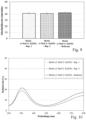
- the deposition rate of the sputtering targets used is in Fig.9 shown, with the left column in Fig.9 the target material from Example 1 (Ex. 1), the middle column corresponds to the target material from Example 2 (Ex. 2) and the right column corresponds to the target material of the reference.
- the reflectivity of the layers produced was used as a criterion for the assessment.
- glass substrates Cornning Eagle XG, 50 ⁇ 50 ⁇ 0.7 mm 3
- the molybdenum-tantalum oxide target materials mentioned above, produced according to Example 1 and Example 2 were sputtered non-reactively under specified process conditions in comparison with the above-mentioned non-inventive molybdenum-tantalum oxide target material (reference).
- the reflection was measured through the glass substrate using a Perkin Elmer Lambda 950 photospectrometer over the specified wavelength range.
- the layer thickness of the molybdenum-tantalum oxide was varied in a range from 40 to 60 nm.
- the results from this series of tests for a molybdenum-tantalum oxide layer thickness of 50 nm are shown in Fig.10 where the reflectivity in (%) is plotted against the wavelength in (nm; nanometers).
- Reflectivity curves from example 1 (example 1; dotted curve) and example 2 (example 2; dashed curve) almost lie on top of each other, except that the reflectivity curve of example 1 is slightly increased in the range of higher wavelengths. The curves lie significantly below the solid reflectivity curve of the non-inventive reference.
- the target materials according to Examples 1 and 2 achieve a lower reflectivity over the wavelength range considered (see Fig.10 ), and this with comparable separation rates (see Fig.9 ). Furthermore, the target materials according to the invention have the other advantages explained above. In particular, due to their electrical conductivity and advantageous phase composition (matrix phase; fine distribution of the second phases), they have a preferred sputtering behavior (uniform sputtering rate while avoiding arcs and particle formation), which has a positive effect on the layer quality (homogeneous layer composition; uniform layer thickness).
- a metallographic section was produced from a representative sample part using dry preparation.
- a sample with an area of approx. 10-15 ⁇ 10-15 mm 2 was cut using a dry cutting method (diamond wire saw, band saw, etc.), cleaned using compressed air, then embedded in phenolic resin while warm and conductive (C-doped), ground and polished. Since at least the MoOs phase portion is water-soluble, dry preparation is important. The section obtained in this way was then analyzed using a light microscope.
- a Raman microscope Horiba LabRAM HR800
- a confocal light microscope Olympus BX41
- a complete Raman spectrum was created for each of the 201 ⁇ 201 measuring points ("Raman mapping").
- Raman spectra are obtained from the backscattered radiation, which is split wavelength-dispersively by an optical grating (300 lines/mm; spectral resolution: 2.6 cm -1 ) and recorded using a CCD detector (1024 ⁇ 256 pixel multichannel CCD; spectral range: 200-1050 nm).
- a microscope objective with 100x magnification and numerical aperture NA of 0.9, which is used to focus the laser beam from the Raman spectrometer, a theoretical measuring point size of 0.7 ⁇ m 2 was achieved.
- the excitation energy density (5 mW/ ⁇ m 2 ) is chosen to be low enough to avoid phase transformations in the sample.
- the penetration depth of the excitation radiation is limited to a few micrometers for molybdenum oxides (in the case of pure MoOs, for example, to approx. 4 ⁇ m).
- the Raman signal was averaged over 1 s (s: second) acquisition time, resulting in a sufficiently good signal-to-noise ratio.
- Horiba LabSpec 6 evaluation software a two-dimensional representation of the surface composition of the sample was created, from which the domain size, area proportions, etc. of the various phases can be determined quantitatively.
- Fig. 1 to 6 reference spectra of (Mo 0.93 Ta 0.07 ) 5 O 14 ( Fig.1 ), Ta 2 O 5 ( Fig.2 ), Mon 18 O 52 ( Fig.3 ), MoO2 ( Fig.4 ), MoOs ( Fig.5 ), Mon 4 O 11 ( Fig.6 ) (in the individual spectra, the intensity (number) of scattered light is plotted against the Raman shift (cm -1 )).
- the analysis and assignment of the Raman spectra is carried out using the "Multivariate Analysis Module" of the above-mentioned evaluation software using the CLS method (classical least square fitting).
- Each measurement point is then assigned a color that corresponds to a metal oxide phase, whereby only the phase with the highest weighting factor c i is used for the color assignment.
- the size (the amount) of the weighting factor c i determines the brightness of the measurement point. This procedure is justified insofar as the spectrum of a measurement point can usually be clearly assigned to a single metal oxide phase.
- the analytical method described here is very well suited for determining the relative phase proportions of the phases in question.
- the relative density of the target material is determined by digital image analysis of light microscopic images of the metallographic section, in which the relative surface area "FA" of the pores is determined. After preparation of the samples, three bright field images were taken each with a size of 1 ⁇ 1mm 2 at 100x magnification, whereby zones of obvious breakouts or other damage patterns such as scratches due to dry preparation were avoided where possible.
- the image area to be measured was set (ROI) to exclude the scale bar.
- the result is the relative area share "FA” of the pores (in percent) and the image colored according to the selected grayscale interval (colored means that this pixel was included in the measurement and was therefore counted as a pore).
- the value (1-FA) for the relative density was determined as the arithmetic mean of three such porosity measurements.
Landscapes
- Chemical & Material Sciences (AREA)
- Engineering & Computer Science (AREA)
- Materials Engineering (AREA)
- Chemical Kinetics & Catalysis (AREA)
- Mechanical Engineering (AREA)
- Metallurgy (AREA)
- Organic Chemistry (AREA)
- Plasma & Fusion (AREA)
- Analytical Chemistry (AREA)
- Physics & Mathematics (AREA)
- Physical Vapour Deposition (AREA)
- Compositions Of Oxide Ceramics (AREA)
- Inorganic Compounds Of Heavy Metals (AREA)
Priority Applications (6)
| Application Number | Priority Date | Filing Date | Title |
|---|---|---|---|
| EP19166312.9A EP3715496B1 (de) | 2019-03-29 | 2019-03-29 | Sputteringtarget zur herstellung molybdänoxidhaltiger schichten |
| JP2021557471A JP7580390B2 (ja) | 2019-03-29 | 2020-03-03 | 酸化モリブデン含有層を製造するためのスパッタリングターゲット |
| CN202080024251.7A CN113614278B (zh) | 2019-03-29 | 2020-03-03 | 用于制备含氧化钼层的溅射靶 |
| PCT/EP2020/055481 WO2020200605A1 (de) | 2019-03-29 | 2020-03-03 | Sputteringtarget zur herstellung molybdänoxidhaltiger schichten |
| KR1020217033119A KR102886784B1 (ko) | 2019-03-29 | 2020-03-03 | 몰리브덴 산화물을 함유하는 층을 제조하기 위한 스퍼터링 타겟 |
| TW109109436A TWI819205B (zh) | 2019-03-29 | 2020-03-20 | 製造含氧化鉬層的濺鍍靶 |
Applications Claiming Priority (1)
| Application Number | Priority Date | Filing Date | Title |
|---|---|---|---|
| EP19166312.9A EP3715496B1 (de) | 2019-03-29 | 2019-03-29 | Sputteringtarget zur herstellung molybdänoxidhaltiger schichten |
Publications (2)
| Publication Number | Publication Date |
|---|---|
| EP3715496A1 EP3715496A1 (de) | 2020-09-30 |
| EP3715496B1 true EP3715496B1 (de) | 2024-07-17 |
Family
ID=66041301
Family Applications (1)
| Application Number | Title | Priority Date | Filing Date |
|---|---|---|---|
| EP19166312.9A Active EP3715496B1 (de) | 2019-03-29 | 2019-03-29 | Sputteringtarget zur herstellung molybdänoxidhaltiger schichten |
Country Status (6)
| Country | Link |
|---|---|
| EP (1) | EP3715496B1 (https=) |
| JP (1) | JP7580390B2 (https=) |
| KR (1) | KR102886784B1 (https=) |
| CN (1) | CN113614278B (https=) |
| TW (1) | TWI819205B (https=) |
| WO (1) | WO2020200605A1 (https=) |
Families Citing this family (5)
| Publication number | Priority date | Publication date | Assignee | Title |
|---|---|---|---|---|
| JP2022014783A (ja) * | 2020-07-07 | 2022-01-20 | 三菱マテリアル株式会社 | 酸化モリブデンスパッタリングターゲット、および、酸化モリブデンスパッタリングターゲットの製造方法 |
| CN114916228B (zh) * | 2020-12-10 | 2023-08-15 | Lt金属株式会社 | 以钼氧化物为主成分的金属氧化物烧结体及包含其的溅射靶材 |
| KR102646917B1 (ko) * | 2021-09-16 | 2024-03-13 | 엘티메탈 주식회사 | 몰리브덴 산화물계 소결체, 상기 소결체를 이용한 박막, 상기 박막을 포함하는 박막트랜지스터 및 디스플레이 장치 |
| TWI839845B (zh) * | 2021-10-06 | 2024-04-21 | 南韓商Lt金屬股份有限公司 | 氧化鉬基燒結體、濺鍍靶材、使用燒結體的氧化物薄膜、包含薄膜的薄膜電晶體及顯示裝置 |
| KR102917229B1 (ko) | 2021-10-14 | 2026-01-28 | 엘티메탈 주식회사 | 몰리브덴 산화물계 소결체, 이를 포함하는 스퍼터링 타겟 및 산화물 박막 |
Family Cites Families (10)
| Publication number | Priority date | Publication date | Assignee | Title |
|---|---|---|---|---|
| EP0852266B1 (en) | 1995-08-23 | 2004-10-13 | Asahi Glass Ceramics Co., Ltd. | Target, process for production thereof, and method of forming highly refractive film |
| CA2533110A1 (en) * | 2003-07-22 | 2005-05-06 | H.C. Starck Inc. | Method of making m002 powders, products made from m002 powders, deposition of m002 thin films, and methods of using such materials |
| US7754185B2 (en) * | 2004-06-29 | 2010-07-13 | H.C. Starck Inc. | Method of making MoO2 powders, products made from MoO2 powders, deposition of MoO2 thin films, and methods of using such materials |
| US20070071985A1 (en) * | 2005-09-29 | 2007-03-29 | Prabhat Kumar | Sputtering target, low resistivity, transparent conductive film, method for producing such film and composition for use therein |
| CN102105619B (zh) * | 2008-06-06 | 2014-01-22 | 出光兴产株式会社 | 氧化物薄膜用溅射靶及其制造方法 |
| JP2013020347A (ja) | 2011-07-08 | 2013-01-31 | Toppan Printing Co Ltd | タッチパネルおよびタッチパネルの製造方法 |
| DE102012112742A1 (de) | 2012-10-23 | 2014-04-24 | Fraunhofer-Gesellschaft zur Förderung der angewandten Forschung e.V. | Hoch absorbierendes Schichtsystem, Verfahren zur Herstellung des Schichtsystems und dafür geeignetes Sputtertarget |
| DE102013103679A1 (de) * | 2013-04-11 | 2014-10-30 | Heraeus Materials Technology Gmbh & Co. Kg | Licht absorbierende Schicht und die Schicht enthaltendes Schichtsystem, Verfahren zur dessen Herstellung und dafür geeignetes Sputtertarget |
| KR102316360B1 (ko) * | 2013-10-29 | 2021-10-22 | 플란제 에스이 | 스퍼터링 타깃 및 제조방법 |
| DE102014111935A1 (de) | 2014-08-20 | 2016-02-25 | Heraeus Deutschland GmbH & Co. KG | Zweilagiges Schichtsystem mit teilabsorbierender Schicht sowie Verfahren und Sputtertarget zur Herstellung dieser Schicht |
-
2019
- 2019-03-29 EP EP19166312.9A patent/EP3715496B1/de active Active
-
2020
- 2020-03-03 JP JP2021557471A patent/JP7580390B2/ja active Active
- 2020-03-03 KR KR1020217033119A patent/KR102886784B1/ko active Active
- 2020-03-03 WO PCT/EP2020/055481 patent/WO2020200605A1/de not_active Ceased
- 2020-03-03 CN CN202080024251.7A patent/CN113614278B/zh active Active
- 2020-03-20 TW TW109109436A patent/TWI819205B/zh active
Also Published As
| Publication number | Publication date |
|---|---|
| KR20210145172A (ko) | 2021-12-01 |
| CN113614278B (zh) | 2024-01-30 |
| JP2022526163A (ja) | 2022-05-23 |
| TW202104623A (zh) | 2021-02-01 |
| TWI819205B (zh) | 2023-10-21 |
| WO2020200605A1 (de) | 2020-10-08 |
| JP7580390B2 (ja) | 2024-11-11 |
| EP3715496A1 (de) | 2020-09-30 |
| CN113614278A (zh) | 2021-11-05 |
| KR102886784B1 (ko) | 2025-11-14 |
Similar Documents
| Publication | Publication Date | Title |
|---|---|---|
| EP3467140B1 (de) | Targetmaterial zur abscheidung von molybdänoxid-schichten | |
| EP3715496B1 (de) | Sputteringtarget zur herstellung molybdänoxidhaltiger schichten | |
| EP3715497B1 (de) | Sputteringtarget zur herstellung molybdänoxidhaltiger schichten | |
| EP2984508B1 (de) | Licht absorbierende schicht und die schicht enthaltendes schichtsystem, verfahren zur herstellung des schichtsystems und dafür geeignetes sputtertarget | |
| EP2912501B1 (de) | Licht absorbierendes schichtsystem und dessen herstellung sowie dafür geeignetes sputtertarget | |
| WO2016026590A1 (de) | Zweilagiges schichtsystem mit teilabsorbierender schicht sowie verfahren und sputtertarget zur herstellung dieser schicht | |
| EP3765427B1 (de) | Verfahren zur herstellung eines polykristallinen keramischen festkörpers | |
| DE102016117048A1 (de) | Sputtertarget zur Herstellung einer Licht absorbierenden Schicht | |
| DE102017102569A1 (de) | Schichtsystem mit einer Schwärzungsschicht, sowie Verfahren und Sputtertarget zur Herstellung derselben | |
| WO2025261656A1 (de) | Mola-sputtertarget |
Legal Events
| Date | Code | Title | Description |
|---|---|---|---|
| PUAI | Public reference made under article 153(3) epc to a published international application that has entered the european phase |
Free format text: ORIGINAL CODE: 0009012 |
|
| STAA | Information on the status of an ep patent application or granted ep patent |
Free format text: STATUS: THE APPLICATION HAS BEEN PUBLISHED |
|
| AK | Designated contracting states |
Kind code of ref document: A1 Designated state(s): AL AT BE BG CH CY CZ DE DK EE ES FI FR GB GR HR HU IE IS IT LI LT LU LV MC MK MT NL NO PL PT RO RS SE SI SK SM TR |
|
| AX | Request for extension of the european patent |
Extension state: BA ME |
|
| STAA | Information on the status of an ep patent application or granted ep patent |
Free format text: STATUS: REQUEST FOR EXAMINATION WAS MADE |
|
| 17P | Request for examination filed |
Effective date: 20210330 |
|
| RBV | Designated contracting states (corrected) |
Designated state(s): AL AT BE BG CH CY CZ DE DK EE ES FI FR GB GR HR HU IE IS IT LI LT LU LV MC MK MT NL NO PL PT RO RS SE SI SK SM TR |
|
| STAA | Information on the status of an ep patent application or granted ep patent |
Free format text: STATUS: EXAMINATION IS IN PROGRESS |
|
| 17Q | First examination report despatched |
Effective date: 20231006 |
|
| GRAP | Despatch of communication of intention to grant a patent |
Free format text: ORIGINAL CODE: EPIDOSNIGR1 |
|
| STAA | Information on the status of an ep patent application or granted ep patent |
Free format text: STATUS: GRANT OF PATENT IS INTENDED |
|
| INTG | Intention to grant announced |
Effective date: 20240221 |
|
| GRAS | Grant fee paid |
Free format text: ORIGINAL CODE: EPIDOSNIGR3 |
|
| GRAA | (expected) grant |
Free format text: ORIGINAL CODE: 0009210 |
|
| STAA | Information on the status of an ep patent application or granted ep patent |
Free format text: STATUS: THE PATENT HAS BEEN GRANTED |
|
| AK | Designated contracting states |
Kind code of ref document: B1 Designated state(s): AL AT BE BG CH CY CZ DE DK EE ES FI FR GB GR HR HU IE IS IT LI LT LU LV MC MK MT NL NO PL PT RO RS SE SI SK SM TR |
|
| REG | Reference to a national code |
Ref country code: CH Ref legal event code: EP |
|
| REG | Reference to a national code |
Ref country code: DE Ref legal event code: R096 Ref document number: 502019011670 Country of ref document: DE |
|
| REG | Reference to a national code |
Ref country code: IE Ref legal event code: FG4D Free format text: LANGUAGE OF EP DOCUMENT: GERMAN |
|
| REG | Reference to a national code |
Ref country code: LT Ref legal event code: MG9D |
|
| REG | Reference to a national code |
Ref country code: NL Ref legal event code: MP Effective date: 20240717 |
|
| PG25 | Lapsed in a contracting state [announced via postgrant information from national office to epo] |
Ref country code: PT Free format text: LAPSE BECAUSE OF FAILURE TO SUBMIT A TRANSLATION OF THE DESCRIPTION OR TO PAY THE FEE WITHIN THE PRESCRIBED TIME-LIMIT Effective date: 20241118 |
|
| PG25 | Lapsed in a contracting state [announced via postgrant information from national office to epo] |
Ref country code: NL Free format text: LAPSE BECAUSE OF FAILURE TO SUBMIT A TRANSLATION OF THE DESCRIPTION OR TO PAY THE FEE WITHIN THE PRESCRIBED TIME-LIMIT Effective date: 20240717 |
|
| PG25 | Lapsed in a contracting state [announced via postgrant information from national office to epo] |
Ref country code: PT Free format text: LAPSE BECAUSE OF FAILURE TO SUBMIT A TRANSLATION OF THE DESCRIPTION OR TO PAY THE FEE WITHIN THE PRESCRIBED TIME-LIMIT Effective date: 20241118 Ref country code: NL Free format text: LAPSE BECAUSE OF FAILURE TO SUBMIT A TRANSLATION OF THE DESCRIPTION OR TO PAY THE FEE WITHIN THE PRESCRIBED TIME-LIMIT Effective date: 20240717 |
|
| PG25 | Lapsed in a contracting state [announced via postgrant information from national office to epo] |
Ref country code: NO Free format text: LAPSE BECAUSE OF FAILURE TO SUBMIT A TRANSLATION OF THE DESCRIPTION OR TO PAY THE FEE WITHIN THE PRESCRIBED TIME-LIMIT Effective date: 20241017 |
|
| PG25 | Lapsed in a contracting state [announced via postgrant information from national office to epo] |
Ref country code: GR Free format text: LAPSE BECAUSE OF FAILURE TO SUBMIT A TRANSLATION OF THE DESCRIPTION OR TO PAY THE FEE WITHIN THE PRESCRIBED TIME-LIMIT Effective date: 20241018 Ref country code: FI Free format text: LAPSE BECAUSE OF FAILURE TO SUBMIT A TRANSLATION OF THE DESCRIPTION OR TO PAY THE FEE WITHIN THE PRESCRIBED TIME-LIMIT Effective date: 20240717 Ref country code: PL Free format text: LAPSE BECAUSE OF FAILURE TO SUBMIT A TRANSLATION OF THE DESCRIPTION OR TO PAY THE FEE WITHIN THE PRESCRIBED TIME-LIMIT Effective date: 20240717 |
|
| PG25 | Lapsed in a contracting state [announced via postgrant information from national office to epo] |
Ref country code: BG Free format text: LAPSE BECAUSE OF FAILURE TO SUBMIT A TRANSLATION OF THE DESCRIPTION OR TO PAY THE FEE WITHIN THE PRESCRIBED TIME-LIMIT Effective date: 20240717 |
|
| PG25 | Lapsed in a contracting state [announced via postgrant information from national office to epo] |
Ref country code: LV Free format text: LAPSE BECAUSE OF FAILURE TO SUBMIT A TRANSLATION OF THE DESCRIPTION OR TO PAY THE FEE WITHIN THE PRESCRIBED TIME-LIMIT Effective date: 20240717 |
|
| PG25 | Lapsed in a contracting state [announced via postgrant information from national office to epo] |
Ref country code: IS Free format text: LAPSE BECAUSE OF FAILURE TO SUBMIT A TRANSLATION OF THE DESCRIPTION OR TO PAY THE FEE WITHIN THE PRESCRIBED TIME-LIMIT Effective date: 20241117 |
|
| PG25 | Lapsed in a contracting state [announced via postgrant information from national office to epo] |
Ref country code: HR Free format text: LAPSE BECAUSE OF FAILURE TO SUBMIT A TRANSLATION OF THE DESCRIPTION OR TO PAY THE FEE WITHIN THE PRESCRIBED TIME-LIMIT Effective date: 20240717 |
|
| PG25 | Lapsed in a contracting state [announced via postgrant information from national office to epo] |
Ref country code: RS Free format text: LAPSE BECAUSE OF FAILURE TO SUBMIT A TRANSLATION OF THE DESCRIPTION OR TO PAY THE FEE WITHIN THE PRESCRIBED TIME-LIMIT Effective date: 20241017 Ref country code: ES Free format text: LAPSE BECAUSE OF FAILURE TO SUBMIT A TRANSLATION OF THE DESCRIPTION OR TO PAY THE FEE WITHIN THE PRESCRIBED TIME-LIMIT Effective date: 20240717 |
|
| PG25 | Lapsed in a contracting state [announced via postgrant information from national office to epo] |
Ref country code: RS Free format text: LAPSE BECAUSE OF FAILURE TO SUBMIT A TRANSLATION OF THE DESCRIPTION OR TO PAY THE FEE WITHIN THE PRESCRIBED TIME-LIMIT Effective date: 20241017 Ref country code: PL Free format text: LAPSE BECAUSE OF FAILURE TO SUBMIT A TRANSLATION OF THE DESCRIPTION OR TO PAY THE FEE WITHIN THE PRESCRIBED TIME-LIMIT Effective date: 20240717 Ref country code: NO Free format text: LAPSE BECAUSE OF FAILURE TO SUBMIT A TRANSLATION OF THE DESCRIPTION OR TO PAY THE FEE WITHIN THE PRESCRIBED TIME-LIMIT Effective date: 20241017 Ref country code: LV Free format text: LAPSE BECAUSE OF FAILURE TO SUBMIT A TRANSLATION OF THE DESCRIPTION OR TO PAY THE FEE WITHIN THE PRESCRIBED TIME-LIMIT Effective date: 20240717 Ref country code: IS Free format text: LAPSE BECAUSE OF FAILURE TO SUBMIT A TRANSLATION OF THE DESCRIPTION OR TO PAY THE FEE WITHIN THE PRESCRIBED TIME-LIMIT Effective date: 20241117 Ref country code: HR Free format text: LAPSE BECAUSE OF FAILURE TO SUBMIT A TRANSLATION OF THE DESCRIPTION OR TO PAY THE FEE WITHIN THE PRESCRIBED TIME-LIMIT Effective date: 20240717 Ref country code: GR Free format text: LAPSE BECAUSE OF FAILURE TO SUBMIT A TRANSLATION OF THE DESCRIPTION OR TO PAY THE FEE WITHIN THE PRESCRIBED TIME-LIMIT Effective date: 20241018 Ref country code: FI Free format text: LAPSE BECAUSE OF FAILURE TO SUBMIT A TRANSLATION OF THE DESCRIPTION OR TO PAY THE FEE WITHIN THE PRESCRIBED TIME-LIMIT Effective date: 20240717 Ref country code: ES Free format text: LAPSE BECAUSE OF FAILURE TO SUBMIT A TRANSLATION OF THE DESCRIPTION OR TO PAY THE FEE WITHIN THE PRESCRIBED TIME-LIMIT Effective date: 20240717 Ref country code: BG Free format text: LAPSE BECAUSE OF FAILURE TO SUBMIT A TRANSLATION OF THE DESCRIPTION OR TO PAY THE FEE WITHIN THE PRESCRIBED TIME-LIMIT Effective date: 20240717 |
|
| PG25 | Lapsed in a contracting state [announced via postgrant information from national office to epo] |
Ref country code: SM Free format text: LAPSE BECAUSE OF FAILURE TO SUBMIT A TRANSLATION OF THE DESCRIPTION OR TO PAY THE FEE WITHIN THE PRESCRIBED TIME-LIMIT Effective date: 20240717 Ref country code: DK Free format text: LAPSE BECAUSE OF FAILURE TO SUBMIT A TRANSLATION OF THE DESCRIPTION OR TO PAY THE FEE WITHIN THE PRESCRIBED TIME-LIMIT Effective date: 20240717 Ref country code: RO Free format text: LAPSE BECAUSE OF FAILURE TO SUBMIT A TRANSLATION OF THE DESCRIPTION OR TO PAY THE FEE WITHIN THE PRESCRIBED TIME-LIMIT Effective date: 20240717 |
|
| REG | Reference to a national code |
Ref country code: DE Ref legal event code: R097 Ref document number: 502019011670 Country of ref document: DE |
|
| PG25 | Lapsed in a contracting state [announced via postgrant information from national office to epo] |
Ref country code: EE Free format text: LAPSE BECAUSE OF FAILURE TO SUBMIT A TRANSLATION OF THE DESCRIPTION OR TO PAY THE FEE WITHIN THE PRESCRIBED TIME-LIMIT Effective date: 20240717 |
|
| PG25 | Lapsed in a contracting state [announced via postgrant information from national office to epo] |
Ref country code: CZ Free format text: LAPSE BECAUSE OF FAILURE TO SUBMIT A TRANSLATION OF THE DESCRIPTION OR TO PAY THE FEE WITHIN THE PRESCRIBED TIME-LIMIT Effective date: 20240717 |
|
| PG25 | Lapsed in a contracting state [announced via postgrant information from national office to epo] |
Ref country code: SK Free format text: LAPSE BECAUSE OF FAILURE TO SUBMIT A TRANSLATION OF THE DESCRIPTION OR TO PAY THE FEE WITHIN THE PRESCRIBED TIME-LIMIT Effective date: 20240717 |
|
| PLBE | No opposition filed within time limit |
Free format text: ORIGINAL CODE: 0009261 |
|
| STAA | Information on the status of an ep patent application or granted ep patent |
Free format text: STATUS: NO OPPOSITION FILED WITHIN TIME LIMIT |
|
| 26N | No opposition filed |
Effective date: 20250422 |
|
| PG25 | Lapsed in a contracting state [announced via postgrant information from national office to epo] |
Ref country code: SE Free format text: LAPSE BECAUSE OF FAILURE TO SUBMIT A TRANSLATION OF THE DESCRIPTION OR TO PAY THE FEE WITHIN THE PRESCRIBED TIME-LIMIT Effective date: 20240717 |
|
| PG25 | Lapsed in a contracting state [announced via postgrant information from national office to epo] |
Ref country code: MC Free format text: LAPSE BECAUSE OF FAILURE TO SUBMIT A TRANSLATION OF THE DESCRIPTION OR TO PAY THE FEE WITHIN THE PRESCRIBED TIME-LIMIT Effective date: 20240717 |
|
| REG | Reference to a national code |
Ref country code: CH Ref legal event code: H13 Free format text: ST27 STATUS EVENT CODE: U-0-0-H10-H13 (AS PROVIDED BY THE NATIONAL OFFICE) Effective date: 20251023 |
|
| PG25 | Lapsed in a contracting state [announced via postgrant information from national office to epo] |
Ref country code: LU Free format text: LAPSE BECAUSE OF NON-PAYMENT OF DUE FEES Effective date: 20250329 |
|
| GBPC | Gb: european patent ceased through non-payment of renewal fee |
Effective date: 20250329 |
|
| REG | Reference to a national code |
Ref country code: BE Ref legal event code: MM Effective date: 20250331 |
|
| PG25 | Lapsed in a contracting state [announced via postgrant information from national office to epo] |
Ref country code: GB Free format text: LAPSE BECAUSE OF NON-PAYMENT OF DUE FEES Effective date: 20250329 |
|
| PG25 | Lapsed in a contracting state [announced via postgrant information from national office to epo] |
Ref country code: FR Free format text: LAPSE BECAUSE OF NON-PAYMENT OF DUE FEES Effective date: 20250331 |
|
| PG25 | Lapsed in a contracting state [announced via postgrant information from national office to epo] |
Ref country code: BE Free format text: LAPSE BECAUSE OF NON-PAYMENT OF DUE FEES Effective date: 20250331 |
|
| PG25 | Lapsed in a contracting state [announced via postgrant information from national office to epo] |
Ref country code: CH Free format text: LAPSE BECAUSE OF NON-PAYMENT OF DUE FEES Effective date: 20250331 |
|
| PG25 | Lapsed in a contracting state [announced via postgrant information from national office to epo] |
Ref country code: IE Free format text: LAPSE BECAUSE OF NON-PAYMENT OF DUE FEES Effective date: 20250329 |
|
| PG25 | Lapsed in a contracting state [announced via postgrant information from national office to epo] |
Ref country code: IT Free format text: LAPSE BECAUSE OF FAILURE TO SUBMIT A TRANSLATION OF THE DESCRIPTION OR TO PAY THE FEE WITHIN THE PRESCRIBED TIME-LIMIT Effective date: 20240717 |
|
| PGFP | Annual fee paid to national office [announced via postgrant information from national office to epo] |
Ref country code: DE Payment date: 20260319 Year of fee payment: 8 |