EP3712447B1 - Verbinder und rahmenstruktur mit verbinder - Google Patents
Verbinder und rahmenstruktur mit verbinder Download PDFInfo
- Publication number
- EP3712447B1 EP3712447B1 EP18878610.7A EP18878610A EP3712447B1 EP 3712447 B1 EP3712447 B1 EP 3712447B1 EP 18878610 A EP18878610 A EP 18878610A EP 3712447 B1 EP3712447 B1 EP 3712447B1
- Authority
- EP
- European Patent Office
- Prior art keywords
- expansion
- bolt
- slot
- connector
- main body
- Prior art date
- Legal status (The legal status is an assumption and is not a legal conclusion. Google has not performed a legal analysis and makes no representation as to the accuracy of the status listed.)
- Active
Links
Images


Classifications
-
- F—MECHANICAL ENGINEERING; LIGHTING; HEATING; WEAPONS; BLASTING
- F16—ENGINEERING ELEMENTS AND UNITS; GENERAL MEASURES FOR PRODUCING AND MAINTAINING EFFECTIVE FUNCTIONING OF MACHINES OR INSTALLATIONS; THERMAL INSULATION IN GENERAL
- F16B—DEVICES FOR FASTENING OR SECURING CONSTRUCTIONAL ELEMENTS OR MACHINE PARTS TOGETHER, e.g. NAILS, BOLTS, CIRCLIPS, CLAMPS, CLIPS OR WEDGES; JOINTS OR JOINTING
- F16B7/00—Connections of rods or tubes, e.g. of non-circular section, mutually, including resilient connections
- F16B7/20—Connections of rods or tubes, e.g. of non-circular section, mutually, including resilient connections using bayonet connections
-
- F—MECHANICAL ENGINEERING; LIGHTING; HEATING; WEAPONS; BLASTING
- F16—ENGINEERING ELEMENTS AND UNITS; GENERAL MEASURES FOR PRODUCING AND MAINTAINING EFFECTIVE FUNCTIONING OF MACHINES OR INSTALLATIONS; THERMAL INSULATION IN GENERAL
- F16B—DEVICES FOR FASTENING OR SECURING CONSTRUCTIONAL ELEMENTS OR MACHINE PARTS TOGETHER, e.g. NAILS, BOLTS, CIRCLIPS, CLAMPS, CLIPS OR WEDGES; JOINTS OR JOINTING
- F16B19/00—Bolts without screw-thread; Pins, including deformable elements; Rivets
- F16B19/04—Rivets; Spigots or the like fastened by riveting
- F16B19/08—Hollow rivets; Multi-part rivets
- F16B19/10—Hollow rivets; Multi-part rivets fastened by expanding mechanically
- F16B19/1027—Multi-part rivets
- F16B19/1036—Blind rivets
- F16B19/1081—Blind rivets fastened by a drive-pin
-
- F—MECHANICAL ENGINEERING; LIGHTING; HEATING; WEAPONS; BLASTING
- F16—ENGINEERING ELEMENTS AND UNITS; GENERAL MEASURES FOR PRODUCING AND MAINTAINING EFFECTIVE FUNCTIONING OF MACHINES OR INSTALLATIONS; THERMAL INSULATION IN GENERAL
- F16B—DEVICES FOR FASTENING OR SECURING CONSTRUCTIONAL ELEMENTS OR MACHINE PARTS TOGETHER, e.g. NAILS, BOLTS, CIRCLIPS, CLAMPS, CLIPS OR WEDGES; JOINTS OR JOINTING
- F16B7/00—Connections of rods or tubes, e.g. of non-circular section, mutually, including resilient connections
- F16B7/04—Clamping or clipping connections
-
- F—MECHANICAL ENGINEERING; LIGHTING; HEATING; WEAPONS; BLASTING
- F16—ENGINEERING ELEMENTS AND UNITS; GENERAL MEASURES FOR PRODUCING AND MAINTAINING EFFECTIVE FUNCTIONING OF MACHINES OR INSTALLATIONS; THERMAL INSULATION IN GENERAL
- F16B—DEVICES FOR FASTENING OR SECURING CONSTRUCTIONAL ELEMENTS OR MACHINE PARTS TOGETHER, e.g. NAILS, BOLTS, CIRCLIPS, CLAMPS, CLIPS OR WEDGES; JOINTS OR JOINTING
- F16B12/00—Jointing of furniture or the like, e.g. hidden from exterior
- F16B12/10—Jointing of furniture or the like, e.g. hidden from exterior using pegs, bolts, tenons, clamps, clips, or the like
- F16B12/28—Jointing of furniture or the like, e.g. hidden from exterior using pegs, bolts, tenons, clamps, clips, or the like for metal furniture parts
- F16B12/32—Jointing of furniture or the like, e.g. hidden from exterior using pegs, bolts, tenons, clamps, clips, or the like for metal furniture parts using clamps, clips, wedges, sliding bolts, or the like
-
- F—MECHANICAL ENGINEERING; LIGHTING; HEATING; WEAPONS; BLASTING
- F16—ENGINEERING ELEMENTS AND UNITS; GENERAL MEASURES FOR PRODUCING AND MAINTAINING EFFECTIVE FUNCTIONING OF MACHINES OR INSTALLATIONS; THERMAL INSULATION IN GENERAL
- F16B—DEVICES FOR FASTENING OR SECURING CONSTRUCTIONAL ELEMENTS OR MACHINE PARTS TOGETHER, e.g. NAILS, BOLTS, CIRCLIPS, CLAMPS, CLIPS OR WEDGES; JOINTS OR JOINTING
- F16B2/00—Friction-grip releasable fastenings
- F16B2/02—Clamps, i.e. with gripping action effected by positive means other than the inherent resistance to deformation of the material of the fastening
- F16B2/14—Clamps, i.e. with gripping action effected by positive means other than the inherent resistance to deformation of the material of the fastening using wedges
-
- F—MECHANICAL ENGINEERING; LIGHTING; HEATING; WEAPONS; BLASTING
- F16—ENGINEERING ELEMENTS AND UNITS; GENERAL MEASURES FOR PRODUCING AND MAINTAINING EFFECTIVE FUNCTIONING OF MACHINES OR INSTALLATIONS; THERMAL INSULATION IN GENERAL
- F16B—DEVICES FOR FASTENING OR SECURING CONSTRUCTIONAL ELEMENTS OR MACHINE PARTS TOGETHER, e.g. NAILS, BOLTS, CIRCLIPS, CLAMPS, CLIPS OR WEDGES; JOINTS OR JOINTING
- F16B21/00—Means for preventing relative axial movement of a pin, spigot, shaft or the like and a member surrounding it; Stud-and-socket releasable fastenings
- F16B21/06—Releasable fastening devices with snap-action
- F16B21/065—Releasable fastening devices with snap-action with an additional locking element
-
- F—MECHANICAL ENGINEERING; LIGHTING; HEATING; WEAPONS; BLASTING
- F16—ENGINEERING ELEMENTS AND UNITS; GENERAL MEASURES FOR PRODUCING AND MAINTAINING EFFECTIVE FUNCTIONING OF MACHINES OR INSTALLATIONS; THERMAL INSULATION IN GENERAL
- F16B—DEVICES FOR FASTENING OR SECURING CONSTRUCTIONAL ELEMENTS OR MACHINE PARTS TOGETHER, e.g. NAILS, BOLTS, CIRCLIPS, CLAMPS, CLIPS OR WEDGES; JOINTS OR JOINTING
- F16B21/00—Means for preventing relative axial movement of a pin, spigot, shaft or the like and a member surrounding it; Stud-and-socket releasable fastenings
- F16B21/06—Releasable fastening devices with snap-action
- F16B21/07—Releasable fastening devices with snap-action in which the socket has a resilient part
-
- F—MECHANICAL ENGINEERING; LIGHTING; HEATING; WEAPONS; BLASTING
- F16—ENGINEERING ELEMENTS AND UNITS; GENERAL MEASURES FOR PRODUCING AND MAINTAINING EFFECTIVE FUNCTIONING OF MACHINES OR INSTALLATIONS; THERMAL INSULATION IN GENERAL
- F16B—DEVICES FOR FASTENING OR SECURING CONSTRUCTIONAL ELEMENTS OR MACHINE PARTS TOGETHER, e.g. NAILS, BOLTS, CIRCLIPS, CLAMPS, CLIPS OR WEDGES; JOINTS OR JOINTING
- F16B21/00—Means for preventing relative axial movement of a pin, spigot, shaft or the like and a member surrounding it; Stud-and-socket releasable fastenings
- F16B21/10—Means for preventing relative axial movement of a pin, spigot, shaft or the like and a member surrounding it; Stud-and-socket releasable fastenings by separate parts
- F16B21/16—Means for preventing relative axial movement of a pin, spigot, shaft or the like and a member surrounding it; Stud-and-socket releasable fastenings by separate parts with grooves or notches in the pin or shaft
- F16B21/18—Means for preventing relative axial movement of a pin, spigot, shaft or the like and a member surrounding it; Stud-and-socket releasable fastenings by separate parts with grooves or notches in the pin or shaft with circlips or like resilient retaining devices, i.e. resilient in the plane of the ring or the like; Details
-
- F—MECHANICAL ENGINEERING; LIGHTING; HEATING; WEAPONS; BLASTING
- F16—ENGINEERING ELEMENTS AND UNITS; GENERAL MEASURES FOR PRODUCING AND MAINTAINING EFFECTIVE FUNCTIONING OF MACHINES OR INSTALLATIONS; THERMAL INSULATION IN GENERAL
- F16B—DEVICES FOR FASTENING OR SECURING CONSTRUCTIONAL ELEMENTS OR MACHINE PARTS TOGETHER, e.g. NAILS, BOLTS, CIRCLIPS, CLAMPS, CLIPS OR WEDGES; JOINTS OR JOINTING
- F16B7/00—Connections of rods or tubes, e.g. of non-circular section, mutually, including resilient connections
- F16B7/04—Clamping or clipping connections
- F16B7/044—Clamping or clipping connections for rods or tubes being in angled relationship
- F16B7/0446—Clamping or clipping connections for rods or tubes being in angled relationship for tubes using the innerside thereof
-
- F—MECHANICAL ENGINEERING; LIGHTING; HEATING; WEAPONS; BLASTING
- F16—ENGINEERING ELEMENTS AND UNITS; GENERAL MEASURES FOR PRODUCING AND MAINTAINING EFFECTIVE FUNCTIONING OF MACHINES OR INSTALLATIONS; THERMAL INSULATION IN GENERAL
- F16B—DEVICES FOR FASTENING OR SECURING CONSTRUCTIONAL ELEMENTS OR MACHINE PARTS TOGETHER, e.g. NAILS, BOLTS, CIRCLIPS, CLAMPS, CLIPS OR WEDGES; JOINTS OR JOINTING
- F16B7/00—Connections of rods or tubes, e.g. of non-circular section, mutually, including resilient connections
- F16B7/22—Connections of rods or tubes, e.g. of non-circular section, mutually, including resilient connections using hooks or like elements
-
- Y—GENERAL TAGGING OF NEW TECHNOLOGICAL DEVELOPMENTS; GENERAL TAGGING OF CROSS-SECTIONAL TECHNOLOGIES SPANNING OVER SEVERAL SECTIONS OF THE IPC; TECHNICAL SUBJECTS COVERED BY FORMER USPC CROSS-REFERENCE ART COLLECTIONS [XRACs] AND DIGESTS
- Y10—TECHNICAL SUBJECTS COVERED BY FORMER USPC
- Y10T—TECHNICAL SUBJECTS COVERED BY FORMER US CLASSIFICATION
- Y10T403/00—Joints and connections
- Y10T403/32—Articulated members
- Y10T403/32254—Lockable at fixed position
- Y10T403/32426—Plural distinct positions
- Y10T403/32442—At least one discrete position
- Y10T403/32451—Step-by-step adjustment
-
- Y—GENERAL TAGGING OF NEW TECHNOLOGICAL DEVELOPMENTS; GENERAL TAGGING OF CROSS-SECTIONAL TECHNOLOGIES SPANNING OVER SEVERAL SECTIONS OF THE IPC; TECHNICAL SUBJECTS COVERED BY FORMER USPC CROSS-REFERENCE ART COLLECTIONS [XRACs] AND DIGESTS
- Y10—TECHNICAL SUBJECTS COVERED BY FORMER USPC
- Y10T—TECHNICAL SUBJECTS COVERED BY FORMER US CLASSIFICATION
- Y10T403/00—Joints and connections
- Y10T403/70—Interfitted members
- Y10T403/7062—Clamped members
- Y10T403/7064—Clamped members by wedge or cam
- Y10T403/7066—Clamped members by wedge or cam having actuator
Definitions
- the present invention discloses a connector and a frame structure using the same.
- the Chinese utility model patent with the publication number CN 206017376U discloses a quick installation structure, including a socket, a bolt and a bolt base.
- the socket is provided with a slot, and the slot is provided with clamping blocks which can be retracted into inner walls of the slot.
- One end of the bolt is provided with clamping grooves in one-to-one correspondence with the clamping blocks, and the bolt is clamped with the clamping grooves through the clamping blocks.
- the socket and the bolt base are respectively connected to different components needing to be connected, and then, the bolt is inserted into the socket to complete quick connection between two components. When disassembly is needed, it is only necessary to apply a reverse pulling force to the two connected components to withdraw the bolt from the socket.
- a tail end of the bolt can slide in the bolt base, and a clamping device is provided between the bolt and the socket. A distance between the two connected components can be adjusted within a certain range, so that the ability to adjust the production accuracy of the frame structure during installation is very good.
- the French patent FR2909141 discloses a connector and DE3621130A1 another connector as defined in the preamble of claim 1.
- the technical problem to be solved by the present invention is to provide a connector and a frame structure using the same.
- the connector achieves quick disassembly and assembly, and also has the advantages of reliable connection, convenient disassembly and assembly and long service life.
- a connector at least includes:
- Each expansion arm is provided with clamping teeth on a surface corresponding to the inner wall of the slot, the side wall of the slot is provided with limiting teeth corresponding to the clamping teeth, and the clamping teeth are meshed with the limiting teeth in a connected state.
- the expansion arm and the slot are connected by the meshing of the clamping teeth.
- an interaction force between the clamping teeth and the limiting teeth can also bear the load together, so that the reliability of connection is better.
- An end part of the acting end is provided with a first limiting block, and a side surface of the first limiting block away from the acting end is provided with a chamfer.
- the connector is configured so that, after the installation is completed, the first limiting block passes through the expansion channel and abuts against the expansion arm, so as to prevent the expansion bolt from retreating from the expansion channel to improve the reliability of connection
- the bolt main body is based on the standard that it can move freely in the slot along the length direction of the slot in a natural state.
- the expansion arm In a connected state, the expansion arm is inserted into the slot, the acting end of the expansion bolt is inserted from an expansion bolt channel and opens the expansion arms to an inner wall direction of the slot, finally, the expansion arm is in contact with an inner wall of the slot, and tight connection is achieved through an acting force between the expansion arm and the inner wall of the slot.
- the connector achieves quick assembly and disassembly between two components to be connected, and has certain gap adjustment capability and good adaptability.
- the present application further has the following beneficial effects.
- the slot is cylindrical, and the expansion arms are uniformly distributed in a ring shape.
- a cross section of the slot is rectangular, and at least one pair of the expansion arms are distributed relatively.
- the expansion arm includes a connecting block, an inner side of the connecting block is provided with a transition slope at the end close to the bolt main body, and the expansion bolt is provided with a second limiting block corresponding to the transition slope and compressing the transition slope.
- the second limiting block is configured to compress the transition slope to prevent the expansion arm from sinking downward on the side close to the bolt main body, and separating from the inner wall of the slot, thus ensuring that there is a sufficient contact area between the expansion arm and the side wall of the slot to improve the reliability of connection.
- a limiting groove corresponding to the connecting block is formed between the first limiting block and the second limiting block, the limiting groove is internally provided with a plurality of bulges for compressing the connecting block, and the highest point of the bulge is lower than that of the first limiting block and the second limiting block.
- the setting of the bulges can ensure that a pressing force of the slot and the expansion bolt on the connecting block is stable and reliable, thereby further improving the reliability of connection.
- a frame structure includes a sectional material I, a sectional material II and the aforementioned connector.
- the socket is detachably connected with the sectional material I
- the bolt is detachably connected with the sectional material II
- the sectional material I is connected with the sectional material II through the connector.
- the connector achieves quick connection and disassembly between sectional materials to be connected.
- the sectional materials can be directly and quickly connected at an installation site, so that the installation flexibility is better, and the cost of storage and transportation is greatly reduced.
- the sectional material II includes a cross beam and a side beam, and the cross beam is detachably connected with the side beam.
- the bolt is connected with the side beam, the bolt further includes an installation part, the installation part is provided with a preset hole, and the cross beam is connected with the side beam and the bolt through a three-in-one connector.
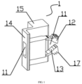
- a connector at least includes a socket 2, a bolt 1 and an expansion bolt 3.
- the socket 2 includes a connection end 21, and a slot 23, which extends along a length direction of the socket 2 from an end surface of the connection end 21, is provided on the socket 2.
- the bolt 1 includes a bolt main body 14 that is adapted to the slot 23, a front end of the bolt main body 14 is provided with at least two expansion arms 16, and the bolt main body 14 is internally provided with an expansion channel 11 which traverses the bolt main body 14 along a length direction.
- FIG. 1 the bolt main body 14 that is adapted to the slot 23, a front end of the bolt main body 14 is provided with at least two expansion arms 16, and the bolt main body 14 is internally provided with an expansion channel 11 which traverses the bolt main body 14 along a length direction.
- the expansion bolt 3 includes a main body of the expansion bolt 3 that matches the expansion channel 11, a front end of the main body of the expansion bolt 3 is provided with an acting end 35 that interacts with the expansion arm 16, and the socket 2 and the bolt 1 are tightly connected by means of an expansion force that is generated by the acting end 35 opening the expansion arms 16.
- the bolt main body 14 is based on the standard that it can move freely in the slot 23 along a length direction of the slot 23 in a natural state.
- the expansion arm 16 is inserted into the slot 23
- the acting end 35 of the expansion bolt 3 is inserted from a channel of the expansion bolt 3 and opens the expansion arms 16 to an inner wall direction of the slot 23
- the expansion arm 16 is in contact with an inner wall of the slot 23, and tight connection is achieved through an acting force between the expansion arm 16 and the inner wall of the slot 23.
- shapes of the slot 23 and the bolt 1 can be set according to needs as long as the slot 23 and the expansion bolt 3 can together compress the expansion arm 16, and the expansion arm 16 need to be reasonably arranged according to the shapes of the slot 23 and the bolt 1.
- the cross section of the slot 23 is preferably rectangular, and at least two of the expansion arms 16 are distributed relatively.
- the expansion arm 16 is provided with clamping teeth 17 on a surfaces corresponding to an inner wall of the slot 23, the side wall of the slot 23 is provided with limiting teeth 22 corresponding to the clamping teeth 17, and the clamping teeth 17 are meshed with the limiting teeth 22 in a connected state.
- the expansion arm 16 and the slot 23 are connected by the meshing of the clamping teeth 17.
- an interaction force between the clamping teeth 17 and the limiting teeth 22 can also bear the load together, so that the reliability of connection is better.
- an end part of the acting end 35 is provided with a first limiting block 34, and a side surface of the first limiting block 34 away from the acting end 35 is provided with a chamfer.
- the first limiting block 34 passes through the channel of the expansion bolt 3 and abuts against the expansion arm 16, so as to prevent the expansion bolt 3 from retreating from the channel of the expansion bolt 3 to improve the reliability of connection.
- the expansion arm 16 includes a connecting block 12, an inner side of the connecting block 12 is provided with a transition slope 13 at an end close to the bolt main body 14, and the expansion bolt 3 is provided with a second limiting block 32 corresponding to the transition slope 13 and compressing the transition slope 13.
- the second limiting block 32 is configured to compress the transition slope 13 to prevent the expansion arm 16 from sinking downward on the side close to the bolt main body 14, and separating from the inner wall of the slot 23 to ensure that there is a sufficient contact area between the expansion arm 16 and the side wall of the slot 23 to improve the reliability of connection.
- a limiting groove corresponding to the connecting block 12 is formed between the first limiting block 34 and the second limiting block 32, the limiting groove is internally provided with a plurality of bulges 33 for compressing the connecting block 12, and the highest point of the bulge 33 is lower than that of the first limiting block 34 and the second limiting block 32.
- the setting of the bulges 33 can ensure that a pressing force of the slot 23 and the expansion bolt 3 on the connecting block 12 is stable and reliable, thereby further improving the reliability of connection.
- the connector achieves quick assembly and disassembly between two components to be connected, and has certain gap adjustment capability and good adaptability.
- the processes of adjusting the gap and finally inserting and locking the expansion bolt 3 and the process of pulling out the expansion bolt 3 for disassembly have no need of tools and can be completed manually by installation personnel, the operation is simple, and the use is convenient.
- the load is borne by the friction force between the socket 2 and the expansion arm 16.
- the expansion arm 16 and the bolt main body 14 are broken.
- the operating end 31 of the expansion bolt 3 can be set larger in size and can abut against the bolt 1 in a connected state, so as to prevent the sudden separation between the connected components to improve the safety of connection.
- the connector of the present application the gap between the two components to be connected is adjusted through the length of the bolt main body 14 inserted into the slot 23.
- no base of the bolt 1 is provided, and the overall length of the connector is greatly reduced, which facilitates the installation and use of the connector.
- a frame structure includes a sectional material I 4, a sectional material II 5 composed of a cross beam 51 and a side beam 52, and the aforementioned connector.
- the bolt 1 further includes an installation part 15, the installation part 15 is provided with a preset hole 18 corresponding to a three-in-one connector 7, and the cross beam 51 is connected with the side beam 52 through the three-in-one connector 7.
- the socket 2 is detachably connected with the sectional material I 4, the bolt 1 is detachably connected with the sectional material II 5, and the sectional material I 4 is connected with the sectional material II 5 through the connector.
- the connector achieves quick connection and disassembly between sectional materials to be connected. When in use, the sectional materials can be directly and quickly connected at an installation site, so that the installation flexibility is better, and the cost of storage and transportation is greatly reduced.
- the three-in-one connector 7 has been widely applied to the prior art, especially the furniture industry.
- the Chinese invention patent with the publication number CN 103256280A discloses a detachable connection device for a hollow extruded plastic board, and the structure and functions of the device are the same as those of the three-in-one connector.
Landscapes
- Engineering & Computer Science (AREA)
- General Engineering & Computer Science (AREA)
- Mechanical Engineering (AREA)
- Mutual Connection Of Rods And Tubes (AREA)
- Connector Housings Or Holding Contact Members (AREA)
- Details Of Connecting Devices For Male And Female Coupling (AREA)
Claims (8)
- - Verbinder, bestehend aus mindestens :eine Buchse (2), die ein Verbindungsende (21) umfasst, wobei an der Buchse (2) ein Schlitz (23) vorgesehen ist, der sich in einer Längsrichtung der Buchse (2) von einer Endfläche des Verbindungsendes (21) aus erstreckt;einen Riegel (1), umfassend einen Riegelhauptkörper (14), der an den Schlitz (23) angepasst ist, wobei ein vorderes Ende des Riegelhauptkörpers (14) mindestens zwei Erweiterungsarme (16) aufweist und der Riegelhauptkörper (14) innen einen Erweiterungskanal (11) aufweist, der den Riegelhauptkörper (14) in einer Längsrichtung durchquert; undeinen Erweiterungsriegel (3), wobei der Erweiterungsriegel (3) einen Erweiterungsriegelhauptkörper umfasst, der dem Erweiterungskanal ( 11) entspricht, wobei ein vorderes Ende des Erweiterungsriegelhauptkörpers ein Aktionsende (35) aufweist, das mit den Erweiterungsarmen (16) zusammenwirkt, und wobei die Buchse (2) und der Riegel (1) mittels einer Erweiterungskraft, die durch das Aktionsende (35) erzeugt wird, das die Erweiterungsarme (16) öffnet, klemmend miteinander verbunden sind ; wobei jeder Erweiterungsarm (16) Klemmzähne (17) auf Flächen aufweist, die den Innenwänden des Schlitzes (23) entsprechen, wobei die Seitenwände des Schlitzes (23) Begrenzungszähne (22) aufweisen, die den Klemmzähnen (17) entsprechen, und wobei die Klemmzähne (17) in einem verbundenen Zustand mit den Begrenzungszähnen (22) in Eingriff sind,dadurch gekennzeichnet, dass ein Endabschnitt des Aktionsendes (35) einen ersten Begrenzungsblock (34) aufweist und eine Seitenfläche des ersten Begrenzungsblocks (34) entfernt von dem Aktionsende (35) eine Abschrägung aufweist, wobei der Verbinder so konfiguriert ist, dass nach Abschluss der Installation, der erste Begrenzungsblock (34) durch den Erweiterungskanal (11) verläuft und an den Erweiterungsarm (16) anstößt, so dass der Erweiterungsriegel (3) daran gehindert wird, sich gegenüber dem Erweiterungskanal (11) zurückzuziehen, um die Zuverlässigkeit der Verbindung zu verbessern.
- - Verbinder nach Anspruch 1, wobei der Schlitz (23) zylindrisch ist und die Erweiterungsarme (16) gleichmäßig in einer Ringform verteilt sind.
- - Verbinder nach Anspruch 1, wobei ein Querschnitt des Schlitzes (23) rechteckig ist und mindestens ein Paar der Erweiterungsarme (16) entgegengesetzt verteilt sind.
- - Verbinder nach Anspruch 1, wobei jeder Erweiterungsarm (16) einen Verbindungsblock (12) umfasst, eine Innenseite des Verbindungsblocks (12) eine Übergangsschräge (13) an dem Ende nahe dem Riegelhauptkörper (14) aufweist, und der Erweiterungsriegel (3) einen zweiten Begrenzungsblock (32) aufweist, der der Übergangsschräge (13) entspricht und die Übergangsschräge (13) zusammendrückt.
- - Verbinder nach Anspruch 4, wobei eine dem Verbindungsblock (12) entsprechende Begrenzungsnut zwischen dem ersten Begrenzungsblock (34) und dem zweiten Begrenzungsblock (32) ausgebildet ist, und die Begrenzungsnut innen eine Vielzahl von Erhebungen (33) zum Zusammendrücken des Verbindungsblocks (12) aufweist.
- - Rahmenstruktur, umfassend modulare Hardware I (4), modulare Hardware II (5) und den Verbinder nach einem der Ansprüche 1 bis 5, wobei die Buchse (2) lösbar mit der modularen Hardware I (4) verbunden ist, der Riegel (1) lösbar mit der modularen Hardware II (5) verbunden ist, und die modulare Hardware I (4) über den Verbinder mit der modularen Hardware II (5) verbunden ist.
- - Rahmenstruktur nach Anspruch 6, wobei das modulare Material II (5) einen Querträger (51) und einen Seitenträger (52) umfasst und der Querträger (51) lösbar mit dem Seitenträger (52) verbunden ist.
- - Rahmenstruktur nach Anspruch 7, wobei der Riegel (1) mit dem Seitenträger (52) verbunden ist, der Riegel (1) ferner einen Installationsabschnitt (15) aufweist, der Installationsabschnitt (15) ein vordefiniertes Loch (18) aufweist, und der Querträger mit dem Seitenträger und dem Riegel über einen Drei-in-einem-Verbinder verbunden ist.
Applications Claiming Priority (2)
| Application Number | Priority Date | Filing Date | Title |
|---|---|---|---|
| CN201711129532.5A CN107747579B (zh) | 2017-11-15 | 2017-11-15 | 连接件及使用该连接件的框架结构 |
| PCT/CN2018/080221 WO2019095601A1 (zh) | 2017-11-15 | 2018-03-23 | 连接件及使用该连接件的框架结构 |
Publications (4)
| Publication Number | Publication Date |
|---|---|
| EP3712447A1 EP3712447A1 (de) | 2020-09-23 |
| EP3712447A4 EP3712447A4 (de) | 2020-12-23 |
| EP3712447B1 true EP3712447B1 (de) | 2025-02-12 |
| EP3712447C0 EP3712447C0 (de) | 2025-02-12 |
Family
ID=61251230
Family Applications (1)
| Application Number | Title | Priority Date | Filing Date |
|---|---|---|---|
| EP18878610.7A Active EP3712447B1 (de) | 2017-11-15 | 2018-03-23 | Verbinder und rahmenstruktur mit verbinder |
Country Status (6)
| Country | Link |
|---|---|
| US (1) | US11629740B2 (de) |
| EP (1) | EP3712447B1 (de) |
| CN (1) | CN107747579B (de) |
| ES (1) | ES3024882T3 (de) |
| PL (1) | PL3712447T3 (de) |
| WO (1) | WO2019095601A1 (de) |
Families Citing this family (13)
| Publication number | Priority date | Publication date | Assignee | Title |
|---|---|---|---|---|
| CN107747579B (zh) * | 2017-11-15 | 2024-07-02 | 杭州康利达卫浴有限公司 | 连接件及使用该连接件的框架结构 |
| CN109404393B (zh) * | 2018-11-08 | 2024-08-02 | 山东意象铝品科技有限公司 | 传动锁紧中梃连接件及其连接方法 |
| CN110186378B (zh) * | 2019-07-03 | 2021-06-25 | 长春禹衡光学有限公司 | 一种光栅尺 |
| CN111188418B (zh) * | 2020-02-21 | 2024-10-22 | 广州地铁设计研究院股份有限公司 | 装配式建筑的锁合机构 |
| CN111577062B (zh) * | 2020-06-12 | 2025-06-10 | 杭州康利达卫浴有限公司 | 通用连接件、连接组件及淋浴房 |
| CN112875873B (zh) * | 2021-01-13 | 2021-10-01 | 哈尔滨工业大学 | 一种交叉流蜂格微生物载体填料 |
| DE102021206087A1 (de) | 2021-06-15 | 2022-12-15 | Zf Active Safety Gmbh | Bremssattel mit einer Blende |
| DE102021206084A1 (de) | 2021-06-15 | 2022-12-15 | Zf Active Safety Gmbh | Bremssattel mit einer Blende |
| US12473756B2 (en) * | 2021-10-27 | 2025-11-18 | The Boeing Company | Adjustable latch systems and methods |
| CN114635504B (zh) * | 2022-04-13 | 2023-10-13 | 杭州潮峰重工钢结构有限公司 | 基于仿古建筑的装配式钢结构框架快装结构及其安装方法 |
| US11739776B1 (en) * | 2022-06-07 | 2023-08-29 | Koch-Glitsch, Lp | Clamp having a lock and a release resisting key |
| CN117022858A (zh) * | 2023-08-10 | 2023-11-10 | 山东纪铭环保科技有限公司 | 一种快装式工业托盘 |
| CN120985235B (zh) * | 2025-10-23 | 2026-02-06 | 大连同泰汽车部件有限公司 | 一种焊接工装拆装装置 |
Citations (1)
| Publication number | Priority date | Publication date | Assignee | Title |
|---|---|---|---|---|
| DE3621130A1 (de) * | 1986-06-24 | 1988-01-21 | Novaplus Verbindungselemente G | Blindniet |
Family Cites Families (20)
| Publication number | Priority date | Publication date | Assignee | Title |
|---|---|---|---|---|
| FR732532A (fr) * | 1932-03-02 | 1932-09-21 | Dispositif permettant le montage et le démontage instantanés des lits et autres meubles ainsi que des charpentes légères et provisoires | |
| GB1491083A (en) * | 1975-03-19 | 1977-11-09 | Newage Kitchens Ltd | Joint assemblies |
| US4488843A (en) * | 1982-07-16 | 1984-12-18 | Illinois Tool Works Inc. | Reusable one piece drive fastener |
| DE3437930A1 (de) * | 1984-10-17 | 1986-06-12 | MOTOS Motor-Technik GmbH, 4512 Wallenhorst | Steckbares verbindungselement |
| FR2724893B1 (fr) * | 1994-09-26 | 1996-12-13 | Valeo Systemes Dessuyage | Platine-support pour un dispositif d'essuie-glace de vehicule automobile |
| US5704746A (en) * | 1997-01-30 | 1998-01-06 | Illinois Tool Works Inc. | Plastic fastener for threaded blind aperture |
| GB9806428D0 (en) * | 1998-03-26 | 1998-05-20 | Ultraframe Uk Ltd | Connecting device |
| DE29918363U1 (de) * | 1999-04-01 | 2000-01-13 | Karl Simon GmbH & Co KG, 78733 Aichhalden | Montageelement für den Möbelbau |
| FR2882114B1 (fr) * | 2005-02-17 | 2008-06-20 | Raymond Et Cie Soc En Commandi | Rivet metallique a fixation demontable |
| FR2909141B3 (fr) * | 2006-11-29 | 2008-10-31 | Kenmark Ind Co Ltd | Unite de mise en prise d'article a combiner |
| US20150233181A1 (en) * | 2012-09-05 | 2015-08-20 | Branach Technology Pty Ltd | Releasable coupling for ladder section and the like |
| CN103256280B (zh) | 2013-03-05 | 2015-05-20 | 周口市五杰塑钢有限公司 | 中空挤塑板可拆连接装置及使用该装置的连接结构、家具 |
| DE102013008503A1 (de) * | 2013-05-15 | 2014-11-20 | Iav Gmbh Ingenieurgesellschaft Auto Und Verkehr | Verbindungssystem mit Dorn und Doppelhülse |
| CN203822777U (zh) * | 2014-03-06 | 2014-09-10 | 重庆赫杰精密机械有限公司 | 检具快速连接结构 |
| GB2539395B (en) * | 2015-06-12 | 2017-11-15 | Make It Fail Ltd | Clamping mechanism |
| US10015895B2 (en) * | 2015-11-13 | 2018-07-03 | Getac Technology Corporation | Casing device and insertion structure thereof |
| CN206017376U (zh) * | 2016-08-26 | 2017-03-15 | 杭州康利达卫浴有限公司 | 一种快速安装结构 |
| US10570937B2 (en) * | 2017-01-10 | 2020-02-25 | Sensorlink Corporation | Clamp sensor systems and methods |
| CN107747579B (zh) * | 2017-11-15 | 2024-07-02 | 杭州康利达卫浴有限公司 | 连接件及使用该连接件的框架结构 |
| CN207437526U (zh) * | 2017-11-15 | 2018-06-01 | 杭州康利达卫浴有限公司 | 一种连接件及使用该连接件的框架结构 |
-
2017
- 2017-11-15 CN CN201711129532.5A patent/CN107747579B/zh active Active
-
2018
- 2018-03-23 PL PL18878610.7T patent/PL3712447T3/pl unknown
- 2018-03-23 ES ES18878610T patent/ES3024882T3/es active Active
- 2018-03-23 EP EP18878610.7A patent/EP3712447B1/de active Active
- 2018-03-23 WO PCT/CN2018/080221 patent/WO2019095601A1/zh not_active Ceased
- 2018-03-23 US US16/763,682 patent/US11629740B2/en active Active
Patent Citations (1)
| Publication number | Priority date | Publication date | Assignee | Title |
|---|---|---|---|---|
| DE3621130A1 (de) * | 1986-06-24 | 1988-01-21 | Novaplus Verbindungselemente G | Blindniet |
Also Published As
| Publication number | Publication date |
|---|---|
| ES3024882T3 (en) | 2025-06-05 |
| US11629740B2 (en) | 2023-04-18 |
| CN107747579B (zh) | 2024-07-02 |
| PL3712447T3 (pl) | 2025-06-02 |
| US20200370581A1 (en) | 2020-11-26 |
| EP3712447A4 (de) | 2020-12-23 |
| EP3712447A1 (de) | 2020-09-23 |
| WO2019095601A1 (zh) | 2019-05-23 |
| CN107747579A (zh) | 2018-03-02 |
| EP3712447C0 (de) | 2025-02-12 |
Similar Documents
| Publication | Publication Date | Title |
|---|---|---|
| EP3712447B1 (de) | Verbinder und rahmenstruktur mit verbinder | |
| CN213270588U (zh) | 一种快速接头 | |
| CN103840316A (zh) | 防松型弹性焊接电缆快速连接装置 | |
| CN207437526U (zh) | 一种连接件及使用该连接件的框架结构 | |
| CN211639192U (zh) | 一种防坠落安全保护结构 | |
| CN211114445U (zh) | 一种用于钢筋连接的快装套筒 | |
| CN110094405B (zh) | 一种卡扣式螺栓及其使用方法 | |
| CN220550758U (zh) | 连接组件及预制构件 | |
| CN110697321A (zh) | 一种便于拆装的组合模块传输带 | |
| CN208564290U (zh) | 一种窗框限位支撑结构 | |
| CN214533869U (zh) | 一种对接锁紧装置 | |
| CN214034090U (zh) | 一种装配式绿色建筑木材 | |
| CN211168501U (zh) | 一种便于拆装的组合模块传输带 | |
| CN210371519U (zh) | 一种家具二合一连体快装连杆 | |
| CN220963952U (zh) | 一种重载连接器 | |
| CN221402153U (zh) | 一种螺纹沟槽式不锈钢三通管 | |
| CN221609186U (zh) | 一种活动驳接爪 | |
| CN217500999U (zh) | 一种二次搭设外架的连墙件 | |
| CN210371839U (zh) | 一种钢丝绳固定用夹具 | |
| CN223918763U (zh) | 一种保压机构及生产线 | |
| CN215858282U (zh) | 一种高抗滑移能力的槽钢连接结构 | |
| CN216041774U (zh) | 一种安全式钢结构节点构件 | |
| CN210769807U (zh) | 销轴的安装结构及采用其制造的凳子 | |
| CN222705947U (zh) | 一种防脱连接器及电缆线束 | |
| CN217234073U (zh) | 一种连体活动垫圈螺母 |
Legal Events
| Date | Code | Title | Description |
|---|---|---|---|
| STAA | Information on the status of an ep patent application or granted ep patent |
Free format text: STATUS: THE INTERNATIONAL PUBLICATION HAS BEEN MADE |
|
| PUAI | Public reference made under article 153(3) epc to a published international application that has entered the european phase |
Free format text: ORIGINAL CODE: 0009012 |
|
| STAA | Information on the status of an ep patent application or granted ep patent |
Free format text: STATUS: REQUEST FOR EXAMINATION WAS MADE |
|
| 17P | Request for examination filed |
Effective date: 20200615 |
|
| AK | Designated contracting states |
Kind code of ref document: A1 Designated state(s): AL AT BE BG CH CY CZ DE DK EE ES FI FR GB GR HR HU IE IS IT LI LT LU LV MC MK MT NL NO PL PT RO RS SE SI SK SM TR |
|
| AX | Request for extension of the european patent |
Extension state: BA ME |
|
| A4 | Supplementary search report drawn up and despatched |
Effective date: 20201125 |
|
| RIC1 | Information provided on ipc code assigned before grant |
Ipc: F16B 19/10 20060101ALI20201119BHEP Ipc: F16B 7/04 20060101ALI20201119BHEP Ipc: F16B 7/20 20060101AFI20201119BHEP |
|
| DAV | Request for validation of the european patent (deleted) | ||
| DAX | Request for extension of the european patent (deleted) | ||
| STAA | Information on the status of an ep patent application or granted ep patent |
Free format text: STATUS: EXAMINATION IS IN PROGRESS |
|
| 17Q | First examination report despatched |
Effective date: 20230413 |
|
| GRAP | Despatch of communication of intention to grant a patent |
Free format text: ORIGINAL CODE: EPIDOSNIGR1 |
|
| STAA | Information on the status of an ep patent application or granted ep patent |
Free format text: STATUS: GRANT OF PATENT IS INTENDED |
|
| INTG | Intention to grant announced |
Effective date: 20240902 |
|
| GRAS | Grant fee paid |
Free format text: ORIGINAL CODE: EPIDOSNIGR3 |
|
| GRAA | (expected) grant |
Free format text: ORIGINAL CODE: 0009210 |
|
| STAA | Information on the status of an ep patent application or granted ep patent |
Free format text: STATUS: THE PATENT HAS BEEN GRANTED |
|
| AK | Designated contracting states |
Kind code of ref document: B1 Designated state(s): AL AT BE BG CH CY CZ DE DK EE ES FI FR GB GR HR HU IE IS IT LI LT LU LV MC MK MT NL NO PL PT RO RS SE SI SK SM TR |
|
| REG | Reference to a national code |
Ref country code: GB Ref legal event code: FG4D |
|
| REG | Reference to a national code |
Ref country code: CH Ref legal event code: EP |
|
| REG | Reference to a national code |
Ref country code: DE Ref legal event code: R096 Ref document number: 602018079173 Country of ref document: DE |
|
| REG | Reference to a national code |
Ref country code: IE Ref legal event code: FG4D |
|
| U01 | Request for unitary effect filed |
Effective date: 20250311 |
|
| PGFP | Annual fee paid to national office [announced via postgrant information from national office to epo] |
Ref country code: GB Payment date: 20250317 Year of fee payment: 8 |
|
| U07 | Unitary effect registered |
Designated state(s): AT BE BG DE DK EE FI FR IT LT LU LV MT NL PT RO SE SI Effective date: 20250417 |
|
| U20 | Renewal fee for the european patent with unitary effect paid |
Year of fee payment: 8 Effective date: 20250422 |
|
| REG | Reference to a national code |
Ref country code: ES Ref legal event code: FG2A Ref document number: 3024882 Country of ref document: ES Kind code of ref document: T3 Effective date: 20250605 |
|
| PG25 | Lapsed in a contracting state [announced via postgrant information from national office to epo] |
Ref country code: RS Free format text: LAPSE BECAUSE OF FAILURE TO SUBMIT A TRANSLATION OF THE DESCRIPTION OR TO PAY THE FEE WITHIN THE PRESCRIBED TIME-LIMIT Effective date: 20250512 |
|
| PGFP | Annual fee paid to national office [announced via postgrant information from national office to epo] |
Ref country code: PL Payment date: 20250402 Year of fee payment: 8 |
|
| PGFP | Annual fee paid to national office [announced via postgrant information from national office to epo] |
Ref country code: ES Payment date: 20250415 Year of fee payment: 8 |
|
| PG25 | Lapsed in a contracting state [announced via postgrant information from national office to epo] |
Ref country code: NO Free format text: LAPSE BECAUSE OF FAILURE TO SUBMIT A TRANSLATION OF THE DESCRIPTION OR TO PAY THE FEE WITHIN THE PRESCRIBED TIME-LIMIT Effective date: 20250512 Ref country code: IS Free format text: LAPSE BECAUSE OF FAILURE TO SUBMIT A TRANSLATION OF THE DESCRIPTION OR TO PAY THE FEE WITHIN THE PRESCRIBED TIME-LIMIT Effective date: 20250612 |
|
| PG25 | Lapsed in a contracting state [announced via postgrant information from national office to epo] |
Ref country code: HR Free format text: LAPSE BECAUSE OF FAILURE TO SUBMIT A TRANSLATION OF THE DESCRIPTION OR TO PAY THE FEE WITHIN THE PRESCRIBED TIME-LIMIT Effective date: 20250212 |
|
| PG25 | Lapsed in a contracting state [announced via postgrant information from national office to epo] |
Ref country code: GR Free format text: LAPSE BECAUSE OF FAILURE TO SUBMIT A TRANSLATION OF THE DESCRIPTION OR TO PAY THE FEE WITHIN THE PRESCRIBED TIME-LIMIT Effective date: 20250513 |
|
| PG25 | Lapsed in a contracting state [announced via postgrant information from national office to epo] |
Ref country code: SM Free format text: LAPSE BECAUSE OF FAILURE TO SUBMIT A TRANSLATION OF THE DESCRIPTION OR TO PAY THE FEE WITHIN THE PRESCRIBED TIME-LIMIT Effective date: 20250212 |
|
| PG25 | Lapsed in a contracting state [announced via postgrant information from national office to epo] |
Ref country code: CZ Free format text: LAPSE BECAUSE OF FAILURE TO SUBMIT A TRANSLATION OF THE DESCRIPTION OR TO PAY THE FEE WITHIN THE PRESCRIBED TIME-LIMIT Effective date: 20250212 |
|
| REG | Reference to a national code |
Ref country code: CH Ref legal event code: H13 Free format text: ST27 STATUS EVENT CODE: U-0-0-H10-H13 (AS PROVIDED BY THE NATIONAL OFFICE) Effective date: 20251023 |
|
| PG25 | Lapsed in a contracting state [announced via postgrant information from national office to epo] |
Ref country code: SK Free format text: LAPSE BECAUSE OF FAILURE TO SUBMIT A TRANSLATION OF THE DESCRIPTION OR TO PAY THE FEE WITHIN THE PRESCRIBED TIME-LIMIT Effective date: 20250212 |
|
| PLBE | No opposition filed within time limit |
Free format text: ORIGINAL CODE: 0009261 |
|
| STAA | Information on the status of an ep patent application or granted ep patent |
Free format text: STATUS: NO OPPOSITION FILED WITHIN TIME LIMIT |
|
| PG25 | Lapsed in a contracting state [announced via postgrant information from national office to epo] |
Ref country code: MC Free format text: LAPSE BECAUSE OF FAILURE TO SUBMIT A TRANSLATION OF THE DESCRIPTION OR TO PAY THE FEE WITHIN THE PRESCRIBED TIME-LIMIT Effective date: 20250212 |
|
| PG25 | Lapsed in a contracting state [announced via postgrant information from national office to epo] |
Ref country code: CH Free format text: LAPSE BECAUSE OF NON-PAYMENT OF DUE FEES Effective date: 20250331 |
|
| PG25 | Lapsed in a contracting state [announced via postgrant information from national office to epo] |
Ref country code: IE Free format text: LAPSE BECAUSE OF NON-PAYMENT OF DUE FEES Effective date: 20250323 |
|
| 26N | No opposition filed |
Effective date: 20251113 |