EP3710697B1 - Einrichtung zur bereitstellung von unter einem vorgebbaren druck stehenden fluiden - Google Patents
Einrichtung zur bereitstellung von unter einem vorgebbaren druck stehenden fluiden Download PDFInfo
- Publication number
- EP3710697B1 EP3710697B1 EP19704786.3A EP19704786A EP3710697B1 EP 3710697 B1 EP3710697 B1 EP 3710697B1 EP 19704786 A EP19704786 A EP 19704786A EP 3710697 B1 EP3710697 B1 EP 3710697B1
- Authority
- EP
- European Patent Office
- Prior art keywords
- pump
- valve
- fluid
- switching position
- pressure
- Prior art date
- Legal status (The legal status is an assumption and is not a legal conclusion. Google has not performed a legal analysis and makes no representation as to the accuracy of the status listed.)
- Active
Links
- 239000012530 fluid Substances 0.000 title claims description 69
- 238000006073 displacement reaction Methods 0.000 claims description 10
- 239000002184 metal Substances 0.000 claims description 6
- 238000002485 combustion reaction Methods 0.000 claims description 3
- 238000011144 upstream manufacturing Methods 0.000 claims description 3
- 238000010531 catalytic reduction reaction Methods 0.000 claims description 2
- XSQUKJJJFZCRTK-UHFFFAOYSA-N Urea Chemical compound NC(N)=O XSQUKJJJFZCRTK-UHFFFAOYSA-N 0.000 description 7
- 239000004202 carbamide Substances 0.000 description 7
- 239000000243 solution Substances 0.000 description 7
- 230000008014 freezing Effects 0.000 description 4
- 238000007710 freezing Methods 0.000 description 4
- 239000003921 oil Substances 0.000 description 4
- 238000002347 injection Methods 0.000 description 3
- 239000007924 injection Substances 0.000 description 3
- 239000007788 liquid Substances 0.000 description 3
- 238000011109 contamination Methods 0.000 description 2
- 230000006378 damage Effects 0.000 description 2
- 238000007789 sealing Methods 0.000 description 2
- 238000000926 separation method Methods 0.000 description 2
- 108010053481 Antifreeze Proteins Proteins 0.000 description 1
- 230000002528 anti-freeze Effects 0.000 description 1
- 230000006835 compression Effects 0.000 description 1
- 238000007906 compression Methods 0.000 description 1
- 230000000694 effects Effects 0.000 description 1
- 239000010687 lubricating oil Substances 0.000 description 1
- 238000009423 ventilation Methods 0.000 description 1
- 238000013022 venting Methods 0.000 description 1
- XLYOFNOQVPJJNP-UHFFFAOYSA-N water Substances O XLYOFNOQVPJJNP-UHFFFAOYSA-N 0.000 description 1
Images


Classifications
-
- F—MECHANICAL ENGINEERING; LIGHTING; HEATING; WEAPONS; BLASTING
- F04—POSITIVE - DISPLACEMENT MACHINES FOR LIQUIDS; PUMPS FOR LIQUIDS OR ELASTIC FLUIDS
- F04B—POSITIVE-DISPLACEMENT MACHINES FOR LIQUIDS; PUMPS
- F04B13/00—Pumps specially modified to deliver fixed or variable measured quantities
-
- F—MECHANICAL ENGINEERING; LIGHTING; HEATING; WEAPONS; BLASTING
- F04—POSITIVE - DISPLACEMENT MACHINES FOR LIQUIDS; PUMPS FOR LIQUIDS OR ELASTIC FLUIDS
- F04B—POSITIVE-DISPLACEMENT MACHINES FOR LIQUIDS; PUMPS
- F04B43/00—Machines, pumps, or pumping installations having flexible working members
- F04B43/08—Machines, pumps, or pumping installations having flexible working members having tubular flexible members
-
- F—MECHANICAL ENGINEERING; LIGHTING; HEATING; WEAPONS; BLASTING
- F04—POSITIVE - DISPLACEMENT MACHINES FOR LIQUIDS; PUMPS FOR LIQUIDS OR ELASTIC FLUIDS
- F04B—POSITIVE-DISPLACEMENT MACHINES FOR LIQUIDS; PUMPS
- F04B53/00—Component parts, details or accessories not provided for in, or of interest apart from, groups F04B1/00 - F04B23/00 or F04B39/00 - F04B47/00
- F04B53/06—Venting
-
- F—MECHANICAL ENGINEERING; LIGHTING; HEATING; WEAPONS; BLASTING
- F04—POSITIVE - DISPLACEMENT MACHINES FOR LIQUIDS; PUMPS FOR LIQUIDS OR ELASTIC FLUIDS
- F04B—POSITIVE-DISPLACEMENT MACHINES FOR LIQUIDS; PUMPS
- F04B53/00—Component parts, details or accessories not provided for in, or of interest apart from, groups F04B1/00 - F04B23/00 or F04B39/00 - F04B47/00
- F04B53/08—Cooling; Heating; Preventing freezing
Definitions
- the invention relates to a device for providing fluids under a predeterminable pressure for the pressure supply of a consumer according to the feature configuration of the preamble of patent claim 1.
- DE 10 2012 205370 A1 is a generic device for providing fluids under a predeterminable pressure for the pressure supply of a consumer, such as a working unit of an SCR (Selective Catalytic Reduction) system for exhaust gas treatment of internal combustion engines, with at least one pump, which is in a between a fluid supply and the Customer-formed fluid circuit removes the fluid in question from the fluid supply and supplies it to the customer, with a line branch containing a throttle point and a valve arrangement being provided in the fluid circuit, which can be actuated into a switching position connecting the fluid supply to the pump, in which a flow path is formed which contains the line branch having the throttle point, and which can be actuated into a second switching position which interrupts the supply to the consumer and in which a flow path connecting the pump to the environment is formed.
- SCR Selective Catalytic Reduction
- DE 10 2012 011975 A1 discloses a comparable device in the form of a valve arrangement with a directional valve device which has a valve housing and at least one valve member movably mounted therein between at least a first and a second switching position and with an actuator device for actuating the valve member, the actuator device having an electrical coil and wherein a permanent magnet is fixed on the valve member.
- the invention has the object of providing a device of the type mentioned at the beginning, which can be produced simply and inexpensively and which can also be operated safely under frost conditions.
- this object is achieved by a device which has the features of claim 1 in its entirety.
- an essential feature of the invention is that the pump is a positive displacement pump, a displacement element being formed by a metal bellows which has the shape of a bellows which encloses a fluid space within the pump housing.
- a metal bellows as a displacement element is particularly advantageous for fluids such as aqueous urea solution, which are capable of creeping and are aggressive, because a clean separation of the fluid circuit from the drive-side pressure medium, such as pressure oil, can be achieved over long periods of operation without sealing problems.
- the problem of the fluid in the pump freezing is avoided in that if the supply to the consumer is interrupted, for example in coordination with the shutdown of the pump, it can be completely or completely ventilated via a flow path formed by the valve arrangement and leading to the environment so that there is little or no freezable fluid in the pump during standstill periods under frost conditions. If the pump is put into operation after ventilation, in the first switching position of the valve arrangement it can be automatically vented via the line branch containing the throttle point and operates as a pure liquid pump while the consumer is being supplied.
- the line branch containing the throttle point can be arranged between the fluid supply and the pressure side of the pump, the suction side of which is in connection with the environment via this in the second switching position of the valve arrangement.
- the check valve forming the throttle point can be part of a pressure limiting valve connected to the pressure side of the pump.
- the fluid circuit can thereby advantageously be implemented with a small number of functional components.
- the arrangement can advantageously also be made such that, in the second switching position of the valve arrangement, the surroundings are connected to the suction side of the pump via this.
- a fluid filter connected upstream of the consumer is arranged in all circuit variants of the fluid circuit.
- the inflow side of the filter can be connected to the valve arrangement and to the environment via a check valve, so that in the second switching position the filter is not included in the flow path through which the pump is ventilated.
- the arrangement can be such that the valve arrangement has, in addition to a first directional valve connected to the pump, a second directional valve which is arranged between the outflow side of the filter connected to the consumer and the fluid supply and can be actuated into a switching position in the second switching position of the first directional valve in which the environment is connected to the suction side of the pump via the filter and the second directional control valve.
- the additional effort caused by the addition of a second directional control valve is counteracted by the predominant advantage that when the pump is pressurized, the filter is also ventilated and, as a result, anti-freeze is also available for the filter.
- the valve arrangement can advantageously have 3/2-way valves and 4/2-way valves, each in the form of electromagnetically actuated slide valves.
- the respective check valve containing the throttle point can have a valve body with fluid connections running at right angles to one another, in which a spring-loaded valve piston, which is coaxially displaceable to one of the fluid connections and has a coaxial through hole, is provided as a closing body, from which a throttle hole branches off at right angles to one of the fluid connections second fluid connection leads.
- the invention is explained on the basis of examples in which the device for supplying a working unit 1 of an SCR system (which is otherwise not shown) with pressurized aqueous urea solution (Adblue) is provided. It goes without saying that the device can advantageously be used for supplying pressure to other types of consumers with other fluids.
- the device has a pressure-actuated pump 3 which, in a fluid circuit 4, draws the aqueous urea solution from a tank 5 containing a fluid supply via a suction line 7 and returns it to the tank 5 via a return line 9.
- a fluid filter 15 connected upstream of the working unit 1 in order to ensure that the working unit 1 is supplied with fluid that is clean from contamination.
- the working unit 1 has, in the manner customary in SCR systems, an electronic control device which, depending on the respective operating state of an internal combustion engine (not shown), feeds the fluid under supply pressure in dosed injection quantities to an injection device which introduces the fluid into the exhaust gas flow.
- a pressure-limiting valve 17 set to the predetermined supply pressure of the working unit 1 has a spring-loaded check valve 19 in the line branch forming the return line 9, which forms a throttle point 18, which is indicated in symbols, which is referred to below Fig. 5 has been dealt with in more detail.
- a valve arrangement with a 3/2-way valve 23 is located in the suction line 7 in front of the suction side 21 of the pump 3.
- the pump 3 is a positive displacement pump, the displacement element being formed by a metal bellows 25 which has the shape of a bellows, which encloses a fluid space 29 within the pump housing 27.
- the pressure line 13 opens on the pressure side 11 via a pressure valve 31 into the fluid space 29, while a suction valve 33 is located on the suction side 21.
- the pump 3 can be operated with pressure medium by means of a drive unit 35, via which the working spaces in a drive cylinder 37 can be supplied with a pressure medium, such as pressure oil or air.
- a piston 39 located in the working cylinder 37 is connected to the metal bellows 35 via a piston rod 41, so that movements of the piston 39 change the volume of the fluid space 29.
- the use of a metal bellows 25 as a displacement element is particularly advantageous for fluids, such as aqueous urea solution, which are capable of creeping and are aggressive, because a clean separation of the fluid circuit 4 from the drive-side pressure medium, such as pressure oil, can be achieved over long periods of operation without sealing problems.
- aqueous urea solution which are capable of creeping and are aggressive
- the piston 39 is pretensioned by means of a compression spring 43 for a displacement movement which reduces the volume of the fluid space 29.
- the drive unit 35 has a switching valve in the form of a 3/2-way valve 45, via which the working chamber 47 in the drive cylinder 34 opposite the spring 43 can be alternately supplied with pressure medium, which is supplied from a pressure connection P, or can be connected to a return line or tank line 49 is, in which a secured by a check valve 51 return filter 53 is located. Between the pressure connection P and the tank line 49 there is a pressure control valve 55 which prescribes a desired drive pressure.
- pressure media such as compressed air or pressure oil are usually available in devices equipped with SCR systems.
- large diesels have their own hydraulic system for supplying lubricating oil.
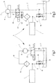
- Fig. 1 and 2 an operating state is shown in which the directional control valve 23 is in a switch position, here referred to as the second switch position, which interrupts the pressure supply to the working unit 1.
- the pump 3 continues to run before it is switched off for the end of operation, it sucks in air from the environment 57 via the directional valve 23, while remaining urea solution is pushed out of the fluid chamber 29 and via the filter 15 and the throttle point 18 in the Check valve 19 of the pressure relief valve 17 is released to the tank 5, so that the pump 3 is ventilated after shutdown and contains little or no freezable fluid.
- the pump 3 When operation is resumed and the directional control valve 23 is switched to the other, first switching position, the pump 3 is automatically vented by sucking in the fluid via the suction line 7 and pushing out the air contained in the fluid space 29 via the line 13 and the throttle point 18 in the return line 9 In normal operation, the pump 3 thus works as a liquid pump.
- the Fig. 3 shows a variant of the fluid circuit 4 in which the valve arrangement has a 4/2-way valve 59, this being in the first switching position corresponding to normal operation of the device.
- the directional control valve 59 connects the suction side 21 of the pump 3 to the environment 57 via a check valve 62, while the suction side 21 of the pump 3 is connected to the tank 5 via the line 7 which forms the suction line during supply operation.
- the pump 3 is therefore ventilated from the surroundings 57 via the check valve 62, while remaining fluid is expelled from the pump 3 via the line 7.
- the directional control valve 59 is switched to the first switching position, the pump 3 is again automatically vented via the suction line 7 and via the throttle point 18 of the check valve 19, which is part of the pressure relief valve 17 located in the return line 9.
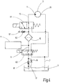
- the valve arrangement has a second directional valve in the form of a 4/2-way valve 63, which is connected to the line branch forming the return line 9, which contains the check valve 19 having the throttle point 18, and is connected to the suction line 7.
- Both directional control valves 61, 63 of the valve arrangement are in the first switching position, which corresponds to normal supply operation.
- the check valve 62 leading to the environment 57 is connected to the inflow side of the filter 15, the outflow side of which is connected to the working unit 1.
- the directional control valve 61 connects the pressure side 11 of the pump 3 with the line 7, which is used as a suction line during normal operation with the suction side 21 of the pump 3.
- the pump 3 is running, it is ventilated from the environment 57 via the check valve 62 and the filter 15 to the suction side 21, while remaining fluid is expelled to the tank 5.
- the pump 3 is vented via the suction line 7, the air being expelled via the throttle point 18, so that the pump 3 again operates as a pure liquid pump.
- the Fig. 5 illustrates an advantageous design of the check valve 19 containing the throttle point 18.
- an inflow-side fluid connection 69 and an outflow-side fluid connection 71 which branches off from the fluid connection 69 at right angles, are located on the valve housing 57.
- a valve piston 73 is mounted in the valve housing 67 coaxially to the fluid connection 69 on the inflow side and is supported by a closing spring 75 biased into the closed position.
- the valve piston 73 has a through hole 77, from which a throttle hole 79, which forms the throttle point 18 and which leads to the downstream fluid connection 71, branches off at right angles.
- the check valve 19 can be set as a pressure relief valve to a prescribable pressure, while at the same time the throttle point 18 is formed with the desired throttling effect by dimensioning the throttle bore 79.
Landscapes
- Engineering & Computer Science (AREA)
- Mechanical Engineering (AREA)
- General Engineering & Computer Science (AREA)
- Exhaust Gas After Treatment (AREA)
- Details Of Reciprocating Pumps (AREA)
Description
- Die Erfindung betrifft eine Einrichtung zur Bereitstellung von unter einem vorgebbaren Druck stehenden Fluiden für die Druckversorgung eines Abnehmers gemäß der Merkmalsausgestaltung des Oberbegriffes des Patentanspruches 1.
- Durch
DE 10 2012 205370 A1 ist eine gattungsmäßige Einrichtung zur Breitstellung von unter einem vorgebbaren Druck stehenden Fluiden für die Druckversorgung eines Abnehmers, wie einer Arbeitseinheit eines SCR (Selective Catalytic Reduction)-Systems zur Abgasbehandlung von Verbrennungsmotoren bekannt, mit mindestens einer Pumpe, die in einem zwischen einem Fluidvorrat und dem Abnehmer gebildeten Fluidkreislauf das betreffende Fluid aus dem Fluidvorrat entnimmt und dem Abnehmer zuführt, wobei im Fluidkreislauf ein eine Drosselstelle enthaltender Leitungszweig und eine Ventilanordnung vorgesehen sind, die in eine den Fluidvorrat mit der Pumpe verbindende Schaltstellung betätigbar ist, bei der ein Strömungsweg gebildet ist, der den die Drosselstelle aufweisenden Leitungszweig enthält, und die in eine zweite die Versorgung des Abnehmers unterbrechende Schaltstellung betätigbar ist, bei der ein die Pumpe mit der Umgebung verbindender Strömungsweg gebildet ist. -
DE 10 2012 011975 A1 offenbart demgegenüber eine vergleichbare Einrichtung in Form einer Ventilanordnung mit einer Wegeventileinrichtung, die ein Ventilgehäuse und wenigstens ein darin zwischen wenigstens einer ersten und einer zweiten Schaltstellung beweglich gelagertes Ventilglied aufweist und mit einer Aktoreinrichtung zur Betätigung des Ventilgliedes, wobei die Aktoreinrichtung eine elektrische Spule aufweist und wobei an dem Ventilglied ein Permanentmagnet festgelegt ist. - Einrichtungen dieser Art sind also Stand der Technik (
DE 10 2012 016 631 A1 ). Wenn Einrichtungen dieser Art für die Versorgung von Arbeitseinheiten benutzt werden, die eine wässrige Harnstofflösung unter einem gegebenen Versorgungsdruck dem Einspritzventil eines SCR-Systems zuführen, verursacht das Gefrieren des Fluids Probleme. Das bei wässrigen Harnstofflösungen (Adblue) enthaltende Wasser dehnt sich bei Gefrieren um 8 % aus, so dass Maßnahmen getroffen werden müssen, um die Einrichtung vor durch das Gefrieren verursachter Beschädigung oder Zerstörung zu schützen. Bekannte Maßnahmen, wie das Bereitstellen elastischer Ausgleichsvolumina, erfordern einen entsprechenden konstruktiven Aufwand und sind daher kostenintensiv. - Im Hinblick auf diese Problematik stellt sich die Erfindung die Aufgabe, eine Einrichtung der eingangs genannten Gattung zur Verfügung zu stellen, die einfach und kostengünstig herstellbar und auch unter Frostbedingungen sicher betreibbar ist.
- Erfindungsgemäß ist diese Aufgabe durch eine Einrichtung gelöst, die die Merkmale des Patentanspruchs 1 in seiner Gesamtheit aufweist.
- Gemäß dem kennzeichnenden Teil des Anspruchs 1 besteht eine wesentliche Besonderheit der Erfindung darin, dass die Pumpe eine Verdrängerpumpe ist, wobei ein Verdrängerelement durch einen Metallbalg gebildet ist, der die Form eines Faltenbalges besitzt, der innerhalb des Pumpengehäuses einen Fluidraum umschließt. Die Benutzung eines Metallbalgs als Verdrängerelement ist bei Fluiden, wie wässrige Harnstofflösung, die kriechfähig und aggressiv sind, besonders vorteilhaft, weil ohne Abdichtprobleme eine saubere Trennung des Fluidkreislaufs vom antriebsseitigen Druckmedium, wie Drucköl, über lange Betriebszeiträume hinweg erreichbar ist.
- Das Problem des Gefrierens von in der Pumpe befindlichem Fluid ist dadurch vermieden, dass bei Unterbrechung der Versorgung des Abnehmers, beispielsweise in zeitlicher Koordination mit dem Abschalten der Pumpe, diese über einen mittels der Ventilanordnung gebildeten, zur Umgebung führenden Strömungsweg ganz oder vollständig belüftet werden kann, so dass sich bei Stillstandsperioden unter Frostbedingungen kein oder wenig gefrierbares Fluid in der Pumpe befindet. Wird die Pumpe nach Belüftung in Betrieb gesetzt, ist sie bei der ersten Schaltstellung der Ventilanordnung über den die Drosselstelle enthaltenden Leitungszweig selbstentlüftbar und arbeitet während der Versorgung des Abnehmers als reine Flüssigkeitspumpe.
- In vorteilhafter Weise kann der die Drosselstelle enthaltende Leitungszweig zwischen dem Fluidvorrat und der Druckseite der Pumpe angeordnet sein, deren Saugseite bei der zweiten Schaltstellung der Ventilanordnung über diese mit der Umgebung in Verbindung ist.
- Bei vorteilhaften Ausführungsbeispielen kann das die Drosselstelle bildende Rückschlagventil Bestandteil eines mit der Druckseite der Pumpe in Verbindung stehenden Druckbegrenzungsventils sein. Der Fluidkreislauf ist dadurch in vorteilhafter Weise mit einer geringen Anzahl von Funktionskomponenten realisierbar.
- Mit Vorteil kann die Anordnung auch so getroffen sein, dass bei der zweiten Schaltstellung der Ventilanordnung über diese die Umgebung mit der Saugseite der Pumpe verbunden ist.
- Um eine sichere Versorgung des Abnehmers mit von Verschmutzungen freiem Fluid zu gewährleisten, ist bei sämtlichen Schaltungsvarianten des Fluidkreislaufs in diesem ein dem Abnehmer vorgeschaltetes Fluidfilter angeordnet.
- Bei besonders vorteilhaften Ausführungsbeispielen kann die Zuströmseite des Filters mit der Ventilanordnung und mit der Umgebung über ein Rückschlagventil verbunden sein, so dass bei der zweiten Schaltstellung der Filter nicht in den Strömungsweg einbezogen ist, über den die Belüftung der Pumpe erfolgt.
- Alternativ kann die Anordnung so getroffen sein, dass die Ventilanordnung außer einem ersten, an der Pumpe angeschlossenen Wegeventil ein zweites Wegeventil aufweist, das zwischen der am Abnehmer angeschlossenen Abströmseite des Filters und dem Fluidvorrat angeordnet und bei der zweiten Schaltstellung des ersten Wegeventils in eine Schaltstellung betätigbar ist, bei der die Umgebung über den Filter und über das zweite Wegeventil mit der Saugseite der Pumpe verbunden ist. Dem durch die Hinzunahme eines zweiten Wegeventils bedingten zusätzlichen Aufwand steht der überwiegende Vorteil entgegen, dass beim Belüften der Pumpe auch der Filter mitbelüftet wird und dadurch auch für den Filter ein Gefrierschutz zur Verfügung steht.
- Die Ventilanordnung kann in vorteilhafter Weise 3/2-Wegeventile sowie 4/2-Wegeventile, jeweils in Form von elektromagnetisch betätigbaren Schieberventilen, aufweisen.
- Mit besonderem Vorteil kann das jeweilige, die Drosselstelle enthaltende Rückschlagventil einen Ventilkörper mit zueinander rechtwinklig verlaufenden Fluidanschlüssen aufweisen, in dem als Schließkörper ein zu einem der Fluidanschlüsse koaxial verschiebbarer, federbelasteter Ventilkolben mit einer koaxialen Durchgangsbohrung vorgesehen ist, von der eine Drosselbohrung rechtwinklig abzweigt, die zum zweiten Fluidanschluss führt.
- Nachstehend ist die Erfindung anhand von in der Zeichnung dargestellten Ausführungsbeispielen im Einzelnen erläutert.
- Es zeigen:
- Fig. 1
- teilweise in schematisch vereinfachter Schnittdarstellung und teilweise in Symboldarstellung ein Ausführungsbeispiel der erfindungsgemäßen Einrichtung;
- Fig. 2
- in Symboldarstellung die hydraulische Schaltung des Fluidkreislaufs des Ausführungsbeispiels, wobei die Antriebseinheit der Pumpe weggelassen ist;
- Fig. 3
- eine der
Fig. 2 entsprechende Darstellung eines abgewandelten Ausführungsbeispiels; - Fig. 4
- eine den
Fig. 2 und 3 entsprechende Darstellung eines weiteren Ausführungsbeispiels; und - Fig. 5
- einen gegenüber einer praktischen Ausführungsform stark vergrößert dargestellten Längsschnitt eines eine Drosselstelle bildenden Rückschlagventils als Bestandteil der Hydraulikschaltung der Ausführungsbeispiele der erfindungsgemäßen Einrichtung.
- Unter Bezugnahme auf die Zeichnungen ist die Erfindung anhand von Beispielen erläutert, bei denen die Einrichtung zur Versorgung einer Arbeitseinheit 1 eines SCR-Systems (das im Übrigen nicht dargestellt ist) mit unter einem Versorgungsdruck stehender, wässriger Harnstofflösung (Adblue) vorgesehen ist. Es versteht sich, dass die Einrichtung für eine Druckversorgung andersartiger Abnehmer mit anderen Fluiden vorteilhaft benutzbar ist.
- Die Einrichtung weist eine druckbetätigte Pumpe 3 auf, die in einem Fluidkreislauf 4 die wässrige Harnstofflösung aus einem einen Fluidvorrat enthaltenden Tank 5 über eine Saugleitung 7 entnimmt und über eine Rücklaufleitung 9 zum Tank 5 zurückführt. In dem Fluidkreislauf 4 befindet sich in der an der Druckseite 11 der Pumpe 3 angeschlossenen Druckleitung 13 ein der Arbeitseinheit 1 vorgeschalteter Fluidfilter 15, um die Versorgung der Arbeitseinheit 1 mit von Verschmutzungen reinem Fluid zu gewährleisten. Die Arbeitseinheit 1 weist in der bei SCR-Systemen üblichen Weise eine elektronische Steuereinrichtung auf, die nach Maßgabe des jeweiligen Betriebszustands eines Verbrennungsmotors (nicht dargestellt) das unter Versorgungsdruck stehende Fluid in dosierten Einspritzmengen einer Einspritzeinrichtung zuführt, die das Fluid in den Abgasstrom einleitet. Ein auf den vorgegebenen Versorgungsdruck der Arbeitseinheit 1 eingestelltes Druckbegrenzungsventil 17 weist in dem die Rücklaufleitung 9 bildenden Leitungszweig ein federbelastetes Rückschlagventil 19 auf, das eine Drosselstelle 18, die in Symboldarstellung angedeutet ist, bildet, worauf unten unter Bezug auf
Fig. 5 näher eingegangen ist. In der Saugleitung 7 befindet sich vor der Saugseite 21 der Pumpe 3 eine Ventilanordnung mit einem 3/2-Wegeventil 23. - Die Pumpe 3 ist eine Verdrängerpumpe, wobei das Verdrängerelement durch einen Metallbalg 25 gebildet ist, der die Form eines Faltenbalges besitzt, der innerhalb des Pumpengehäuses 27 einen Fluidraum 29 umschließt. In der bei Verdrängerpumpen üblichen Weise mündet die Druckleitung 13 an der Druckseite 11 über ein Druckventil 31 in den Fluidraum 29, während sich an der Saugseite 21 ein Saugventil 33 befindet.
- Die Pumpe 3 ist mittels einer Antriebseinheit 35 druckmittelbetätigbar, über die Arbeitsräume in einem Antriebszylinder 37 mit einem Druckmedium, wie Drucköl oder Luft, versorgbar sind. Ein im Arbeitszylinder 37 befindlicher Kolben 39 ist über eine Kolbenstange 41 mit dem Metallbalg 35 verbunden, so dass Bewegungen des Kolbens 39 das Volumen des Fluidraums 29 verändern. Die Benutzung eines Metallbalgs 25 als Verdrängerelement ist bei Fluiden, wie wässrige Harnstofflösung, die kriechfähig und aggressiv sind, besonders vorteilhaft, weil ohne Abdichtprobleme eine saubere Trennung des Fluidkreislaufs 4 vom antriebsseitigen Druckmedium, wie Drucköl, über lange Betriebszeiträume hinweg erreichbar ist. Wie
Fig. 1 zeigt, ist der Kolben 39 mittels einer Druckfeder 43 für eine das Volumen des Fluidraums 29 verringernde Verschiebebewegung vorgespannt. Die Antriebseinheit 35 weist ein Schaltventil in Form eines 3/2-Wegeventils 45 auf, über das der der Feder 43 gegenüberliegende Arbeitsraum 47 im Antriebszylinder 34 abwechselnd mit Druckmedium, das von einem Druckanschluss P geliefert ist, versorgbar oder mit einer Rückleitung oder Tankleitung 49 verbindbar ist, in der sich ein durch ein Rückschlagventil 51 abgesichertes Rücklauffilter 53 befindet. Zwischen dem Druckanschluss P und der Tankleitung 49 befindet sich ein einen gewünschten Antriebsdruck vorgebendes Druckregelventil 55. Für die Versorgung des Antriebszylinders 37 mit einem Druckmittel stehen bei mit SCR-Systemen ausgerüsteten Einrichtungen üblicherweise Druckmedien, wie Druckluft oder Drucköl, zur Verfügung. Beispielsweise haben Großdiesel ein eigenes hydraulisches System zur Schmierölversorgung. Es ist aber auch möglich, ein Kompaktaggregat zu installieren, welches eine hydraulische Versorgung des Arbeitszylinders 37 sicherstellt. - In den
Fig. 1 und2 ist ein Betriebszustand dargestellt, bei dem sich das Wegeventil 23 in einer die Druckversorgung der Arbeitseinheit 1 unterbrechenden Schaltstellung, hier als zweite Schaltstellung bezeichnet, befindet. Wenn hierbei die Pumpe 3, bevor sie für die Beendigung des Betriebs abgeschaltet ist, noch weiterläuft, saugt sie über das Wegeventil 23 aus der Umgebung 57 Luft an, während verbliebene Harnstofflösung aus dem Fluidraum 29 ausgeschoben und über den Filter 15 und die Drosselstelle 18 im Rückschlagventil 19 des Druckbegrenzungsventils 17 zum Tank 5 abgegeben wird, so dass die Pumpe 3 nach Stillsetzen belüftet ist und wenig oder kein gefrierbares Fluid enthält. Bei Wiederaufnahme des Betriebs und Umschalten des Wegeventils 23 in die andere, erste Schaltstellung, entlüftet sich die Pumpe 3 selbsttätig durch Ansaugen des Fluids über die Saugleitung 7 und Ausschieben der im Fluidraum 29 enthaltenden Luft über die Leitung 13 und die Drosselstelle 18 in der Rücklaufleitung 9. Im Normalbetrieb arbeitet die Pumpe 3 somit als eine Flüssigkeitspumpe. - Die
Fig. 3 zeigt eine Variante des Fluidkreislaufs 4, bei der die Ventilanordnung ein 4/2-Wegeventil 59 aufweist, wobei sich dieses in der dem Normalbetrieb der Einrichtung entsprechenden ersten Schaltstellung befindet. Beim Umschalten in die zweite Schaltstellung verbindet das Wegeventil 59 die Saugseite 21 der Pumpe 3 über ein Rückschlagventil 62 mit der Umgebung 57, während die Saugseite 21 der Pumpe 3 über die beim Versorgungsbetrieb die Saugleitung bildende Leitung 7 mit dem Tank 5 verbunden ist. Bei der zweiten Schaltstellung des Wegeventils 59 belüftet sich die Pumpe 3 daher über das Rückschlagventil 62 von der Umgebung 57 her, während verbliebenes Fluid aus der Pumpe 3 über die Leitung 7 ausgeschoben wird. Bei Umschalten des Wegeventils 59 in die erste Schaltstellung entlüftet sich die Pumpe 3 wiederum selbsttätig über die Saugleitung 7 und über die Drosselstelle 18 des Rückschlagventils 19, das Bestandteil des in der Rücklaufleitung 9 befindlichen Druckbegrenzungsventils 17 ist. - Bei der Variante von
Fig. 4 weist die Ventilanordnung außer dem mit der Pumpe 3 unmittelbar verbundenen 3/2-Wegeventil 61 ein zweites Wegeventil in Form eines 4/2-Wegeventils 63 auf, das an den die Rücklaufleitung 9 bildenden Leitungszweig, der das die Drosselstelle 18 aufweisende Rückschlagventil 19 enthält, sowie an der Saugleitung 7 angeschlossen ist. Bei der Darstellung derFig. 4 befinden sich beide Wegeventile 61, 63 der Ventilanordnung in der ersten Schaltstellung, die dem normalen Versorgungsbetrieb entspricht. Wie beiFig. 4 ist das zur Umgebung 57 führende Rückschlagventil 62 an der Zuströmseite des Filters 15 angeschlossen, dessen Abströmseite mit der Arbeitseinheit 1 in Verbindung ist. Bei Umschalten der Ventilanordnung in die zweite Schaltstellung der Wegeventile 61, 63 für die Belüftung der Pumpe 3 verbindet das Wegeventil 61 die Druckseite 11 der Pumpe 3 mit der beim Normalbetrieb als Saugleitung dienenden Leitung 7. Gleichzeitig verbindet das zweite Wegeventil 63 die Abströmseite des Filters 15 mit der Saugseite 21 der Pumpe 3. Bei laufender Pumpe 3 belüftet sich diese daher von der Umgebung 57 her über das Rückschlagventil 62 sowie den Filter 15 zur Saugseite 21, während verbliebenes Fluid zum Tank 5 ausgestoßen wird. Bei Umschalten in die ersten Schaltstellungen der Wegeventile 61, 63, wie inFig. 4 dargestellt, entlüftet sich die Pumpe 3 über die Saugleitung 7, wobei die Luft über die Drosselstelle 18 ausgeschoben wird, so dass die Pumpe 3 wiederum als reine Flüssigkeitspumpe arbeitet. - Die
Fig. 5 verdeutlicht eine vorteilhafte Bauweise des die Drosselstelle 18 enthaltenden Rückschlagventils 19. Wie ersichtlich ist, befinden sich am Ventilgehäuse 57 ein zuströmseitiger Fluidanschluss 69 und ein abströmseitiger Fluidanschluss 71, der vom Fluidanschluss 69 rechtwinklig abzweigt. Für Verschluss oder Freigabe der Abzweigstelle zwischen den Fluidanschlüssen 69 und 71 ist ein Ventilkolben 73 im Ventilgehäuse 67 koaxial zum zuströmseitigen Fluidanschluss 69 gelagert und durch eine Schließfeder 75 in die Schließstellung vorgespannt. Zur Bildung der Drosselstelle 18 weist der Ventilkolben 73 eine Durchgangsbohrung 77 auf, von der eine die Drosselstelle 18 bildende Drosselbohrung 79 rechtwinklig abzweigt, die zum abströmseitigen Fluidanschluss 71 führt. Entsprechend der mittels einer Stellschraube 81 eingestellten Federhärte der Schließfeder 75 ist das Rückschlagventil 19 als Druckbegrenzungsventil auf einen vorgebbaren Druck einstellbar, während gleichzeitig durch Bemessung der Drosselbohrung 79 die Drosselstelle 18 mit gewünschter Drosselwirkung gebildet ist.
Claims (10)
- Einrichtung zur Bereitstellung von unter einem vorgebbaren Druck stehenden Fluiden für die Druckversorgung eines Abnehmers, wie einer Arbeitseinheit (1) eines SCR(Selective Catalytic Reduktion)-Systems zur Abgasbehandlung von Verbrennungsmotoren, mit mindestens einer Pumpe (3), die in einem zwischen einem Fluidvorrat (5) und dem Abnehmer (1) gebildeten Fluidkreislauf (4) das betreffende Fluid aus dem Fluidvorrat (5) entnimmt und dem Abnehmer (1) zuführt, wobei im Fluidkreislauf (4) ein eine Drosselstelle (18) enthaltender Leitungszweig (9) und eine Ventilanordnung (23, 59, 61, 63) vorgesehen sind, die in eine den Fluidvorrat (5) mit der Pumpe (3) verbindende Schaltstellung betätigbar ist, bei der ein Strömungsweg gebildet ist, der den die Drosselstelle (18) aufweisenden Leitungszweig (9) enthält, und die in eine zweite, die Versorgung des Abnehmers unterbrechende Schaltstellung betätigbar ist, bei der ein die Pumpe (3) mit der Umgebung (57) verbindender Strömungsweg gebildet ist, dadurch gekennzeichnet, dass die Pumpe (3) eine Verdrängerpumpe ist, wobei ein Verdrängerelement durch ein Metallbalg (25) gebildet ist, der die Form eines Faltenbalges besitzt, der innerhalb des Pumpengehäuses (27) einen Fluidraum (29) umschließt.
- Einrichtung nach Anspruch 1, dadurch gekennzeichnet, dass der die Drosselstelle (18) enthaltende Leitungszweig (9) zwischen dem Fluidvorrat (5) und der Druckseite (11) der Pumpe (3) angeordnet ist, deren Saugseite (21) bei der zweiten Schaltstellung der Ventilanordnung über diese mit der Umgebung (57) in Verbindung ist.
- Einrichtung nach Anspruch 1 oder 2, dadurch gekennzeichnet, dass die Drosselstelle (18) durch eine im Schließkörper (73) eines Rückschlagventils (19) befindliche Drosselbohrung (79) gebildet ist.
- Einrichtung nach Anspruch 3, dadurch gekennzeichnet, dass das die Drosselstelle (18) bildende Rückschlagventil (19) Bestandteil eines mit der Druckseite (11) der Pumpe (3) in Verbindung stehenden Druckbegrenzungsventils (17) ist.
- Einrichtung nach einem der vorstehenden Ansprüche, dadurch gekennzeichnet, dass bei der zweiten Schaltstellung der Ventilanordnung (23, 59, 61, 63) über diese die Umgebung (57) mit der Saugseite (21) der Pumpe (3) verbunden ist.
- Einrichtung nach einem der vorstehenden Ansprüche, dadurch gekennzeichnet, dass im Fluidkreislauf (4), dem Abnehmer (1) vorgeschaltet, ein Fluidfilter (15) angeordnet ist.
- Einrichtung nach Anspruch 6, dadurch gekennzeichnet, dass die Zuströmseite des Filters (15) mit der Ventilanordnung (59, 61) und mit der Umgebung (57) über ein Rückschlagventil (62) verbunden ist.
- Einrichtung nach einem der vorstehenden Ansprüche 6 oder 7, dadurch gekennzeichnet, dass die Ventilanordnung außer einem ersten, an der Pumpe (3) angeschlossenen Wegeventil (23, 59, 61) ein zweites Wegeventil (63) aufweist, das zwischen der am Abnehmer (1) angeschlossenen Abströmseite des Filters (15) und dem Fluidvorrat (5) angeordnet und bei der zweiten Schaltstellung des ersten Wegeventils (61) in eine Schaltstellung betätigbar ist, bei der die Umgebung (57) über den Filter (15) und über das zweite Wegeventil (63) mit der Saugseite (21) der Pumpe (3) verbunden ist.
- Einrichtung nach einem der vorstehenden Ansprüche 3 bis 8, dadurch gekennzeichnet, dass die Ventilanordnung 3/2-Wegeventile (23, 61) sowie 4/2-Wegeventile (59, 63), jeweils in Form von elektromagnetisch betätigbaren Schieberventilen, aufweist.
- Einrichtung nach einem der vorstehenden Ansprüche 3 bis 9, dadurch gekennzeichnet, dass das jeweilige, die Drosselstelle (18) enthaltende Rückschlagventil (19) einen Ventilkörper (67) mit zueinander rechtwinklig verlaufenden Fluidanschlüssen (69, 71) aufweist, in dem als Schließkörper ein zu einem (69) der Fluidanschlüsse (69, 71) koaxial verschiebbarer, federbelasteter Ventilkolben (73) mit einer koaxialen Durchgangsbohrung (77) vorgesehen ist, von der eine Drosselbohrung (79) rechtwinklig abzweigt, die zum anderen Fluidanschluss (71) führt.
Applications Claiming Priority (2)
| Application Number | Priority Date | Filing Date | Title |
|---|---|---|---|
| DE102018001523.9A DE102018001523A1 (de) | 2018-02-27 | 2018-02-27 | Einrichtung zur Bereitstellung von unter einem vorgebbaren Druck stehenden Fluiden |
| PCT/EP2019/053239 WO2019166207A1 (de) | 2018-02-27 | 2019-02-11 | Einrichtung zur bereitstellung von unter einem vorgebbaren druck stehenden fluiden |
Publications (2)
| Publication Number | Publication Date |
|---|---|
| EP3710697A1 EP3710697A1 (de) | 2020-09-23 |
| EP3710697B1 true EP3710697B1 (de) | 2021-10-06 |
Family
ID=65409078
Family Applications (1)
| Application Number | Title | Priority Date | Filing Date |
|---|---|---|---|
| EP19704786.3A Active EP3710697B1 (de) | 2018-02-27 | 2019-02-11 | Einrichtung zur bereitstellung von unter einem vorgebbaren druck stehenden fluiden |
Country Status (3)
| Country | Link |
|---|---|
| EP (1) | EP3710697B1 (de) |
| DE (1) | DE102018001523A1 (de) |
| WO (1) | WO2019166207A1 (de) |
Families Citing this family (3)
| Publication number | Priority date | Publication date | Assignee | Title |
|---|---|---|---|---|
| DE102021000327A1 (de) | 2021-01-22 | 2022-07-28 | Hydac Fluidtechnik Gmbh | Pumpenvorrichtung |
| DE102021002116A1 (de) | 2021-04-22 | 2022-10-27 | Hydac Fluidtechnik Gmbh | Pumpenvorrichtung |
| DE102021003639A1 (de) * | 2021-07-14 | 2023-01-19 | Hydac Technology Gmbh | Fördereinrichtung |
Family Cites Families (5)
| Publication number | Priority date | Publication date | Assignee | Title |
|---|---|---|---|---|
| DE102011088217A1 (de) * | 2011-12-12 | 2013-06-13 | Robert Bosch Gmbh | Dosieranordnung für ein flüssiges Abgasnachbehandlungsmittel und Dosierverfahren |
| DE102012205370A1 (de) * | 2012-04-02 | 2013-10-02 | Robert Bosch Gmbh | 3/2-Wegeventil |
| DE102012011975B4 (de) * | 2012-06-15 | 2018-09-20 | Rolf Prettl | Ventilanordnung und Tankmodul für ein Harnstoffeinspritzsystem |
| DE102012016631A1 (de) | 2012-08-22 | 2014-02-27 | Hydac Electronic Gmbh | Einrichtung zur Bereitstellung von unter einem vorgebbaren Druck stehenden Fluiden |
| DE102016216366A1 (de) * | 2016-08-31 | 2018-03-01 | Robert Bosch Gmbh | Dosiersystem für eine Abgasnachbehandlung einer Brennkraftmaschine |
-
2018
- 2018-02-27 DE DE102018001523.9A patent/DE102018001523A1/de not_active Withdrawn
-
2019
- 2019-02-11 WO PCT/EP2019/053239 patent/WO2019166207A1/de unknown
- 2019-02-11 EP EP19704786.3A patent/EP3710697B1/de active Active
Also Published As
| Publication number | Publication date |
|---|---|
| DE102018001523A1 (de) | 2019-08-29 |
| WO2019166207A1 (de) | 2019-09-06 |
| EP3710697A1 (de) | 2020-09-23 |
Similar Documents
| Publication | Publication Date | Title |
|---|---|---|
| EP3710697B1 (de) | Einrichtung zur bereitstellung von unter einem vorgebbaren druck stehenden fluiden | |
| DE102010021399A1 (de) | Hydraulisch betätigte Nockenwellenverstellvorrichtung | |
| DE102009038869B4 (de) | Vorrichtung zum dosierten Ausgeben eines Schmiermittels | |
| EP2128443A1 (de) | Pumpenelement | |
| EP2817516B1 (de) | Pumpe für ein hochdruckreinigungsgerät und hochdruckreinigungsgerät | |
| WO2020120064A1 (de) | Regelbare schraubenspindelpumpe | |
| WO2017125108A1 (de) | Hydraulische schaltanordnung für ein kraftfahrzeug | |
| DE10117418A1 (de) | Oszillierende Verdrängerpumpe | |
| DE102004005790A1 (de) | Steuerung | |
| DE102008004569A1 (de) | Hubkolbenverdichter | |
| DE102010064114B4 (de) | Pumpe mit einer Drossel | |
| DE102019000488B4 (de) | Vorrichtung zum Bereitstellen eines unter einem vorgebbaren Druck stehenden Fluids | |
| EP1970556A1 (de) | Injektor | |
| DE102007057446A1 (de) | Fluidfördereinrichtung und Ventileinrichtung sowie Verfahren zum Betreiben einer Fluidfördereinrichtung | |
| EP1504173A1 (de) | Druckversorgungseinrichtung f r eine elektrohydraulische ven tilsteuerung von gaswechselventilen in brennkraftmaschinen | |
| DE102014204496A1 (de) | Drehschieberanordnung | |
| EP2049795A1 (de) | Kolben einer fahrzeugbremsanlagen-kolbenpumpe | |
| EP2694816B1 (de) | Luftregler für kompressoren, insbesondere schraubenkompressoren | |
| DE19512143C1 (de) | Druckabschneidungsventil mit Wechselventilkolben | |
| WO2016005018A1 (de) | Einrichtung zur bereitstellung von unter einem vorgebbaren druck stehenden fluiden | |
| DE102012018451A1 (de) | Wegeventil mit einer Mehrzahl kugelförmiger Dichtelemente | |
| DE102017222202A1 (de) | Kraftstofffördereinrichtung für kryogene Kraftstoffe | |
| EP3308019B1 (de) | Hubkolbenpumpe mit eingangsseitiger förderstrombegrenzung | |
| DE202012100564U1 (de) | Pumpe für ein Hochdruckreinigungsgerät und Hochdruckreinigungsgerät | |
| DE10257065B4 (de) | Kompressor |
Legal Events
| Date | Code | Title | Description |
|---|---|---|---|
| STAA | Information on the status of an ep patent application or granted ep patent |
Free format text: STATUS: UNKNOWN |
|
| STAA | Information on the status of an ep patent application or granted ep patent |
Free format text: STATUS: THE INTERNATIONAL PUBLICATION HAS BEEN MADE |
|
| PUAI | Public reference made under article 153(3) epc to a published international application that has entered the european phase |
Free format text: ORIGINAL CODE: 0009012 |
|
| STAA | Information on the status of an ep patent application or granted ep patent |
Free format text: STATUS: REQUEST FOR EXAMINATION WAS MADE |
|
| 17P | Request for examination filed |
Effective date: 20200617 |
|
| AK | Designated contracting states |
Kind code of ref document: A1 Designated state(s): AL AT BE BG CH CY CZ DE DK EE ES FI FR GB GR HR HU IE IS IT LI LT LU LV MC MK MT NL NO PL PT RO RS SE SI SK SM TR |
|
| AX | Request for extension of the european patent |
Extension state: BA ME |
|
| RIN1 | Information on inventor provided before grant (corrected) |
Inventor name: HEROLD, FRANK Inventor name: GROH, CHRISTIAN Inventor name: KORN, JEROME |
|
| GRAP | Despatch of communication of intention to grant a patent |
Free format text: ORIGINAL CODE: EPIDOSNIGR1 |
|
| STAA | Information on the status of an ep patent application or granted ep patent |
Free format text: STATUS: GRANT OF PATENT IS INTENDED |
|
| DAV | Request for validation of the european patent (deleted) | ||
| DAX | Request for extension of the european patent (deleted) | ||
| INTG | Intention to grant announced |
Effective date: 20210528 |
|
| GRAS | Grant fee paid |
Free format text: ORIGINAL CODE: EPIDOSNIGR3 |
|
| GRAA | (expected) grant |
Free format text: ORIGINAL CODE: 0009210 |
|
| STAA | Information on the status of an ep patent application or granted ep patent |
Free format text: STATUS: THE PATENT HAS BEEN GRANTED |
|
| AK | Designated contracting states |
Kind code of ref document: B1 Designated state(s): AL AT BE BG CH CY CZ DE DK EE ES FI FR GB GR HR HU IE IS IT LI LT LU LV MC MK MT NL NO PL PT RO RS SE SI SK SM TR |
|
| REG | Reference to a national code |
Ref country code: GB Ref legal event code: FG4D Free format text: NOT ENGLISH |
|
| REG | Reference to a national code |
Ref country code: CH Ref legal event code: EP Ref country code: AT Ref legal event code: REF Ref document number: 1436462 Country of ref document: AT Kind code of ref document: T Effective date: 20211015 |
|
| REG | Reference to a national code |
Ref country code: DE Ref legal event code: R096 Ref document number: 502019002454 Country of ref document: DE |
|
| REG | Reference to a national code |
Ref country code: IE Ref legal event code: FG4D Free format text: LANGUAGE OF EP DOCUMENT: GERMAN |
|
| REG | Reference to a national code |
Ref country code: LT Ref legal event code: MG9D |
|
| REG | Reference to a national code |
Ref country code: NL Ref legal event code: MP Effective date: 20211006 |
|
| PG25 | Lapsed in a contracting state [announced via postgrant information from national office to epo] |
Ref country code: RS Free format text: LAPSE BECAUSE OF FAILURE TO SUBMIT A TRANSLATION OF THE DESCRIPTION OR TO PAY THE FEE WITHIN THE PRESCRIBED TIME-LIMIT Effective date: 20211006 Ref country code: LT Free format text: LAPSE BECAUSE OF FAILURE TO SUBMIT A TRANSLATION OF THE DESCRIPTION OR TO PAY THE FEE WITHIN THE PRESCRIBED TIME-LIMIT Effective date: 20211006 Ref country code: FI Free format text: LAPSE BECAUSE OF FAILURE TO SUBMIT A TRANSLATION OF THE DESCRIPTION OR TO PAY THE FEE WITHIN THE PRESCRIBED TIME-LIMIT Effective date: 20211006 Ref country code: BG Free format text: LAPSE BECAUSE OF FAILURE TO SUBMIT A TRANSLATION OF THE DESCRIPTION OR TO PAY THE FEE WITHIN THE PRESCRIBED TIME-LIMIT Effective date: 20220106 |
|
| PG25 | Lapsed in a contracting state [announced via postgrant information from national office to epo] |
Ref country code: IS Free format text: LAPSE BECAUSE OF FAILURE TO SUBMIT A TRANSLATION OF THE DESCRIPTION OR TO PAY THE FEE WITHIN THE PRESCRIBED TIME-LIMIT Effective date: 20220206 Ref country code: SE Free format text: LAPSE BECAUSE OF FAILURE TO SUBMIT A TRANSLATION OF THE DESCRIPTION OR TO PAY THE FEE WITHIN THE PRESCRIBED TIME-LIMIT Effective date: 20211006 Ref country code: PT Free format text: LAPSE BECAUSE OF FAILURE TO SUBMIT A TRANSLATION OF THE DESCRIPTION OR TO PAY THE FEE WITHIN THE PRESCRIBED TIME-LIMIT Effective date: 20220207 Ref country code: PL Free format text: LAPSE BECAUSE OF FAILURE TO SUBMIT A TRANSLATION OF THE DESCRIPTION OR TO PAY THE FEE WITHIN THE PRESCRIBED TIME-LIMIT Effective date: 20211006 Ref country code: NO Free format text: LAPSE BECAUSE OF FAILURE TO SUBMIT A TRANSLATION OF THE DESCRIPTION OR TO PAY THE FEE WITHIN THE PRESCRIBED TIME-LIMIT Effective date: 20220106 Ref country code: NL Free format text: LAPSE BECAUSE OF FAILURE TO SUBMIT A TRANSLATION OF THE DESCRIPTION OR TO PAY THE FEE WITHIN THE PRESCRIBED TIME-LIMIT Effective date: 20211006 Ref country code: LV Free format text: LAPSE BECAUSE OF FAILURE TO SUBMIT A TRANSLATION OF THE DESCRIPTION OR TO PAY THE FEE WITHIN THE PRESCRIBED TIME-LIMIT Effective date: 20211006 Ref country code: HR Free format text: LAPSE BECAUSE OF FAILURE TO SUBMIT A TRANSLATION OF THE DESCRIPTION OR TO PAY THE FEE WITHIN THE PRESCRIBED TIME-LIMIT Effective date: 20211006 Ref country code: GR Free format text: LAPSE BECAUSE OF FAILURE TO SUBMIT A TRANSLATION OF THE DESCRIPTION OR TO PAY THE FEE WITHIN THE PRESCRIBED TIME-LIMIT Effective date: 20220107 Ref country code: ES Free format text: LAPSE BECAUSE OF FAILURE TO SUBMIT A TRANSLATION OF THE DESCRIPTION OR TO PAY THE FEE WITHIN THE PRESCRIBED TIME-LIMIT Effective date: 20211006 |
|
| REG | Reference to a national code |
Ref country code: DE Ref legal event code: R097 Ref document number: 502019002454 Country of ref document: DE |
|
| PG25 | Lapsed in a contracting state [announced via postgrant information from national office to epo] |
Ref country code: SM Free format text: LAPSE BECAUSE OF FAILURE TO SUBMIT A TRANSLATION OF THE DESCRIPTION OR TO PAY THE FEE WITHIN THE PRESCRIBED TIME-LIMIT Effective date: 20211006 Ref country code: SK Free format text: LAPSE BECAUSE OF FAILURE TO SUBMIT A TRANSLATION OF THE DESCRIPTION OR TO PAY THE FEE WITHIN THE PRESCRIBED TIME-LIMIT Effective date: 20211006 Ref country code: RO Free format text: LAPSE BECAUSE OF FAILURE TO SUBMIT A TRANSLATION OF THE DESCRIPTION OR TO PAY THE FEE WITHIN THE PRESCRIBED TIME-LIMIT Effective date: 20211006 Ref country code: EE Free format text: LAPSE BECAUSE OF FAILURE TO SUBMIT A TRANSLATION OF THE DESCRIPTION OR TO PAY THE FEE WITHIN THE PRESCRIBED TIME-LIMIT Effective date: 20211006 Ref country code: DK Free format text: LAPSE BECAUSE OF FAILURE TO SUBMIT A TRANSLATION OF THE DESCRIPTION OR TO PAY THE FEE WITHIN THE PRESCRIBED TIME-LIMIT Effective date: 20211006 Ref country code: CZ Free format text: LAPSE BECAUSE OF FAILURE TO SUBMIT A TRANSLATION OF THE DESCRIPTION OR TO PAY THE FEE WITHIN THE PRESCRIBED TIME-LIMIT Effective date: 20211006 |
|
| PLBE | No opposition filed within time limit |
Free format text: ORIGINAL CODE: 0009261 |
|
| STAA | Information on the status of an ep patent application or granted ep patent |
Free format text: STATUS: NO OPPOSITION FILED WITHIN TIME LIMIT |
|
| 26N | No opposition filed |
Effective date: 20220707 |
|
| PG25 | Lapsed in a contracting state [announced via postgrant information from national office to epo] |
Ref country code: MC Free format text: LAPSE BECAUSE OF FAILURE TO SUBMIT A TRANSLATION OF THE DESCRIPTION OR TO PAY THE FEE WITHIN THE PRESCRIBED TIME-LIMIT Effective date: 20211006 |
|
| REG | Reference to a national code |
Ref country code: CH Ref legal event code: PL |
|
| REG | Reference to a national code |
Ref country code: BE Ref legal event code: MM Effective date: 20220228 |
|
| PG25 | Lapsed in a contracting state [announced via postgrant information from national office to epo] |
Ref country code: LU Free format text: LAPSE BECAUSE OF NON-PAYMENT OF DUE FEES Effective date: 20220211 Ref country code: AL Free format text: LAPSE BECAUSE OF FAILURE TO SUBMIT A TRANSLATION OF THE DESCRIPTION OR TO PAY THE FEE WITHIN THE PRESCRIBED TIME-LIMIT Effective date: 20211006 |
|
| PG25 | Lapsed in a contracting state [announced via postgrant information from national office to epo] |
Ref country code: SI Free format text: LAPSE BECAUSE OF FAILURE TO SUBMIT A TRANSLATION OF THE DESCRIPTION OR TO PAY THE FEE WITHIN THE PRESCRIBED TIME-LIMIT Effective date: 20211006 |
|
| PG25 | Lapsed in a contracting state [announced via postgrant information from national office to epo] |
Ref country code: FR Free format text: LAPSE BECAUSE OF NON-PAYMENT OF DUE FEES Effective date: 20220228 |
|
| PG25 | Lapsed in a contracting state [announced via postgrant information from national office to epo] |
Ref country code: LI Free format text: LAPSE BECAUSE OF NON-PAYMENT OF DUE FEES Effective date: 20220228 Ref country code: IE Free format text: LAPSE BECAUSE OF NON-PAYMENT OF DUE FEES Effective date: 20220211 Ref country code: CH Free format text: LAPSE BECAUSE OF NON-PAYMENT OF DUE FEES Effective date: 20220228 |
|
| PG25 | Lapsed in a contracting state [announced via postgrant information from national office to epo] |
Ref country code: BE Free format text: LAPSE BECAUSE OF NON-PAYMENT OF DUE FEES Effective date: 20220228 |
|
| PG25 | Lapsed in a contracting state [announced via postgrant information from national office to epo] |
Ref country code: IT Free format text: LAPSE BECAUSE OF FAILURE TO SUBMIT A TRANSLATION OF THE DESCRIPTION OR TO PAY THE FEE WITHIN THE PRESCRIBED TIME-LIMIT Effective date: 20211006 |
|
| GBPC | Gb: european patent ceased through non-payment of renewal fee |
Effective date: 20230211 |
|
| PG25 | Lapsed in a contracting state [announced via postgrant information from national office to epo] |
Ref country code: GB Free format text: LAPSE BECAUSE OF NON-PAYMENT OF DUE FEES Effective date: 20230211 |
|
| PG25 | Lapsed in a contracting state [announced via postgrant information from national office to epo] |
Ref country code: GB Free format text: LAPSE BECAUSE OF NON-PAYMENT OF DUE FEES Effective date: 20230211 |
|
| PG25 | Lapsed in a contracting state [announced via postgrant information from national office to epo] |
Ref country code: MK Free format text: LAPSE BECAUSE OF FAILURE TO SUBMIT A TRANSLATION OF THE DESCRIPTION OR TO PAY THE FEE WITHIN THE PRESCRIBED TIME-LIMIT Effective date: 20211006 Ref country code: CY Free format text: LAPSE BECAUSE OF FAILURE TO SUBMIT A TRANSLATION OF THE DESCRIPTION OR TO PAY THE FEE WITHIN THE PRESCRIBED TIME-LIMIT Effective date: 20211006 |
|
| PGFP | Annual fee paid to national office [announced via postgrant information from national office to epo] |
Ref country code: DE Payment date: 20240229 Year of fee payment: 6 |
|
| PG25 | Lapsed in a contracting state [announced via postgrant information from national office to epo] |
Ref country code: HU Free format text: LAPSE BECAUSE OF FAILURE TO SUBMIT A TRANSLATION OF THE DESCRIPTION OR TO PAY THE FEE WITHIN THE PRESCRIBED TIME-LIMIT; INVALID AB INITIO Effective date: 20190211 |
|
| PG25 | Lapsed in a contracting state [announced via postgrant information from national office to epo] |
Ref country code: TR Free format text: LAPSE BECAUSE OF FAILURE TO SUBMIT A TRANSLATION OF THE DESCRIPTION OR TO PAY THE FEE WITHIN THE PRESCRIBED TIME-LIMIT Effective date: 20211006 |
|
| PG25 | Lapsed in a contracting state [announced via postgrant information from national office to epo] |
Ref country code: MT Free format text: LAPSE BECAUSE OF FAILURE TO SUBMIT A TRANSLATION OF THE DESCRIPTION OR TO PAY THE FEE WITHIN THE PRESCRIBED TIME-LIMIT Effective date: 20211006 |