EP3710317B1 - Wischblatt - Google Patents
Wischblatt Download PDFInfo
- Publication number
- EP3710317B1 EP3710317B1 EP18789385.4A EP18789385A EP3710317B1 EP 3710317 B1 EP3710317 B1 EP 3710317B1 EP 18789385 A EP18789385 A EP 18789385A EP 3710317 B1 EP3710317 B1 EP 3710317B1
- Authority
- EP
- European Patent Office
- Prior art keywords
- area
- wiper
- region
- elasticity
- wiper blade
- Prior art date
- Legal status (The legal status is an assumption and is not a legal conclusion. Google has not performed a legal analysis and makes no representation as to the accuracy of the status listed.)
- Active
Links
Images



Classifications
-
- B—PERFORMING OPERATIONS; TRANSPORTING
- B60—VEHICLES IN GENERAL
- B60S—SERVICING, CLEANING, REPAIRING, SUPPORTING, LIFTING, OR MANOEUVRING OF VEHICLES, NOT OTHERWISE PROVIDED FOR
- B60S1/00—Cleaning of vehicles
- B60S1/02—Cleaning windscreens, windows or optical devices
- B60S1/04—Wipers or the like, e.g. scrapers
- B60S1/32—Wipers or the like, e.g. scrapers characterised by constructional features of wiper blade arms or blades
- B60S1/38—Wiper blades
-
- B—PERFORMING OPERATIONS; TRANSPORTING
- B60—VEHICLES IN GENERAL
- B60S—SERVICING, CLEANING, REPAIRING, SUPPORTING, LIFTING, OR MANOEUVRING OF VEHICLES, NOT OTHERWISE PROVIDED FOR
- B60S1/00—Cleaning of vehicles
- B60S1/02—Cleaning windscreens, windows or optical devices
- B60S1/04—Wipers or the like, e.g. scrapers
- B60S1/32—Wipers or the like, e.g. scrapers characterised by constructional features of wiper blade arms or blades
- B60S1/38—Wiper blades
- B60S1/3848—Flat-type wiper blade, i.e. without harness
- B60S1/3874—Flat-type wiper blade, i.e. without harness with a reinforcing vertebra
- B60S1/3875—Flat-type wiper blade, i.e. without harness with a reinforcing vertebra rectangular section
- B60S1/3877—Flat-type wiper blade, i.e. without harness with a reinforcing vertebra rectangular section embedded in the squeegee
-
- B—PERFORMING OPERATIONS; TRANSPORTING
- B60—VEHICLES IN GENERAL
- B60S—SERVICING, CLEANING, REPAIRING, SUPPORTING, LIFTING, OR MANOEUVRING OF VEHICLES, NOT OTHERWISE PROVIDED FOR
- B60S1/00—Cleaning of vehicles
- B60S1/02—Cleaning windscreens, windows or optical devices
- B60S1/04—Wipers or the like, e.g. scrapers
- B60S1/32—Wipers or the like, e.g. scrapers characterised by constructional features of wiper blade arms or blades
- B60S1/38—Wiper blades
- B60S1/3848—Flat-type wiper blade, i.e. without harness
- B60S1/3874—Flat-type wiper blade, i.e. without harness with a reinforcing vertebra
- B60S1/3875—Flat-type wiper blade, i.e. without harness with a reinforcing vertebra rectangular section
- B60S1/3879—Flat-type wiper blade, i.e. without harness with a reinforcing vertebra rectangular section placed in side grooves in the squeegee
-
- B—PERFORMING OPERATIONS; TRANSPORTING
- B60—VEHICLES IN GENERAL
- B60S—SERVICING, CLEANING, REPAIRING, SUPPORTING, LIFTING, OR MANOEUVRING OF VEHICLES, NOT OTHERWISE PROVIDED FOR
- B60S1/00—Cleaning of vehicles
- B60S1/02—Cleaning windscreens, windows or optical devices
- B60S1/04—Wipers or the like, e.g. scrapers
- B60S1/32—Wipers or the like, e.g. scrapers characterised by constructional features of wiper blade arms or blades
- B60S1/38—Wiper blades
- B60S2001/3827—Wiper blades characterised by the squeegee or blade rubber or wiping element
-
- B—PERFORMING OPERATIONS; TRANSPORTING
- B60—VEHICLES IN GENERAL
- B60S—SERVICING, CLEANING, REPAIRING, SUPPORTING, LIFTING, OR MANOEUVRING OF VEHICLES, NOT OTHERWISE PROVIDED FOR
- B60S1/00—Cleaning of vehicles
- B60S1/02—Cleaning windscreens, windows or optical devices
- B60S1/04—Wipers or the like, e.g. scrapers
- B60S1/32—Wipers or the like, e.g. scrapers characterised by constructional features of wiper blade arms or blades
- B60S1/38—Wiper blades
- B60S2001/3827—Wiper blades characterised by the squeegee or blade rubber or wiping element
- B60S2001/3836—Wiper blades characterised by the squeegee or blade rubber or wiping element characterised by cross-sectional shape
Definitions
- the invention relates to a wiper blade according to the species of the independent claim.
- wiper blades There are already numerous wiper blades known, for example from DE 100 44 913 A1 , which comprise a resilient support rail and a wiper strip, the wiper strip being attached to the support rail. Further state of the art is through the EP 1 591 330 A1 , the FR 2 918 618 A1 , the WO 2011/000403 A1 , the FR 2 846 929 A1 , as well as the CN 104 691 508 A known.
- Such wiper blades have a relatively high overall height. Depending on the structure of the wiper strip, this can lead to unpleasant wind noise and the wiping pattern is further impaired by unfavorable aerodynamics.
- the wiper blade according to the invention with the features of the main claim has the advantage that the wiper lip has a substantially rigid cross-sectional structure and the wiper lip is held in cross-section between a first bending area and a second bending area. Become this way Noise is minimized, an optimal wiping result is achieved and a low overall height is achieved.
- a first attachment area is provided for attaching the wiper lip to the mounting rail, which adjoins at least the first bending area. It is just as simple and therefore advantageous if a second fastening area is provided, which adjoins the second bending area and is provided for fastening the wiper lip to the mounting rail.
- the first bending area and/or the second bending area has at least one support shoulder for supporting the wiper lip.
- the wiper lip has an essentially triangular outer contour in cross section.
- the first bending area has a first stabilization area and a first elasticity area.
- the second bending area has a second stabilization area and a second elasticity area.
- first area of elasticity or the second area of elasticity adjoins the wiper lip directly.
- a particularly good wiping pattern is achieved when the first support shoulder is provided on the first stabilization area.
- the support rail is designed as a spring rail with a flat cross section and longitudinal edges, with the first fastening area and/or the second fastening area enclosing the longitudinal edges in the manner of a clamp.
- the support rail is divided in two in the longitudinal direction and comprises a first rail part and a second rail part, with the first fastening area holding the wiper strip between the first rail part and the second rail part.
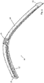
- a wiper blade 10 according to the invention is shown in a perspective view.
- the wiper blade 10 according to the invention comprises a wiper strip 12 which, in the mounted position, is mounted on a window 14 ( figure 2 ) rests.
- the wiper blade 10 is essentially elongate in shape and has an end cap 16 at the ends of its longitudinal extension, which end caps 16 close off the wiper blade 10 in the longitudinal direction.
- a fastening element 20 is also arranged on the side facing away from the wiper strip 12 and is used to fasten the wiper blade 10 to a wiper arm (not shown for the sake of clarity).
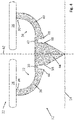
- FIG 2 a cross section through a wiper blade 10 not claimed is shown in detail.
- the wiper blade 10 has a mounting rail 22 to which the wiper strip 12 is attached.
- the support rail 22 is designed to be divided here, so that it comprises a first rail part 24 and a second rail part 26 .
- a one-piece design is also possible and sensible.
- the wiper strip 12 is glued to the underside of the support rail 22 facing the pane 14 .
- the wiper strip 12 has a first attachment area 28 and a second attachment area 30 .
- a flexible, first bending area 32 adjoins the first attachment area 28 .
- the second attachment area 30 is followed by a flexible, second bending area 34 .
- the first bending area 32 comprises a flexible, first stabilizing area 36 and a first elastic area 38, which is even more flexible or elastic than the first stabilizing area 36.
- the second bending area 34 comprises a flexible, second stabilizing area 40 and a second elastic area 42, which is also is even more flexible than the second region of stability 40.
- the wiper strip 12 further includes a wiper lip 44 which is substantially triangular in shape in cross section and is substantially rigid in cross section is trained. The wiper lip 44 is held by the first area of elasticity 38 and by the second area of elasticity 42 so that the essentially rigid wiper lip 44 can move in the direction of the first area of stability 36 or the second area of stability 40 .
- the first bending area 32 or more precisely, the first stability area 36 of the first bending area 32, and the second bending area 34 or its stability area 40, have an elongate cross-section and lead from the first attachment area 28 or the second attachment area 30 initially approximately perpendicularly from the Support rail 22 down and have a horizontal area after a bend of about 90 degrees.
- the first stability area 36 and the second stability area 40 are thus approximately L-shaped in cross section, or vice versa.
- the wiper lip 44 adjoins the horizontal areas of the first stability area 36 or second stability area 40 via the first area of elasticity 38 or second area of elasticity 42 .
- the thickness of the first stability area 36 and the second stability area 40 is approximately 1 millimeter in cross section.
- the thickness of the first area of elasticity 38 and the second area of elasticity 42 is approximately 0.4 millimeters here.
- the first area of elasticity 38 and the second area of elasticity 42 protrude in cross-section approximately centrally from the end face of the L-leg of the first stability area 36 and the second stability area 40, respectively.
- the width of the first area of elasticity 38 and the second area of elasticity 42, ie the distance between the first stability area 36 or second stability area 40 and the wiper lip 44 is approximately 0.3 millimeters.
- the wiper lip 44 Since the wiper lip 44 is held between the first area of elasticity 38 and the second area of elasticity 42, it has a certain mobility due to the elasticity of the first flexible area 32 and the second flexible area 34. The wiper lip 44 can therefore rotate or tilt slightly. To limit this mobility, a first support shoulder 46 and a second support shoulder 48 are provided, against which the wiper lip 44 strikes when the wiper lip 44 rotates or tilts too much about an imaginary axis perpendicular to the plane of the drawing.
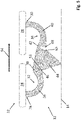
- figure 3 is a variation of the in figure 2 shown wiper bar shown. In order to avoid repetition, only the difference in the first fastening area 28 and the second fastening area 30 is described here. Otherwise, the embodiment is identical to that of FIG figure 2 . The statements to figure 2 therefore continue to apply here.
- the first fastening area 28 of the wiper strip 12 comprises a clamp-like first embracing 50 which nestles around a first longitudinal edge 52 of the support rail 22 .
- the second fastening area 30 has a second embracing 54 which nestles around a second longitudinal edge 56 of the mounting rail 22 .
- adhesive or another attachment means can also be used.
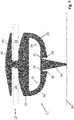
- FIG 4 the cross section is off figure 2 shown in a variation.
- the support rail 22 holds the wiper strip 12 with the first rail part 24 and the second rail part 26. As in the previous examples, however, the support rail 22 can also be made in one piece here.
- the wiper strip 12 is glued to the mounting rail 22, but another attachment can also be used here, for example the one shown in figure 3 shown, are used.
- the first fastening area 28 is followed by the first stabilizing area 36 of the first bending area 32, which is also elongated, L-shaped or C-shaped here.
- the thickness of the first stabilization area 36, to which the first elasticity area 38 adjoins is slightly increased and thus the first support shoulder 46 on the side of the stabilization area 36 facing away from the mounting rail 22 educated.
- the first area of elasticity 38 extended approximately centrally from the first stabilizing area 36, here the first area of elasticity 38 is formed on the side of the stabilizing area 36 facing the mounting rail 22, so that on the side facing away from the mounting rail 22 the first supporting shoulder 46 is formed and on which the Support rail 22 side facing the first elasticity region 38 is arranged.
- the wiper lip 44 adjoins the first area of elasticity 38 .
- the end face of the first stability area 36, which forms the first support shoulder 46 runs here approximately perpendicularly to a plane formed by the support rail 22; likewise the face of the second stability area 40.
- the wiper lip 44 is essentially triangular in shape and has a first indentation 58 in cross section at the level of the first support shoulder 46, which is provided for receiving the first support shoulder 46 during operation. This is in figure 5 shown in detail.
- the thickness of the first stability area 36 and the second stability area 40 is approximately 0.85 millimeters here, the thickness of the first area of elasticity 38 and the second area of elasticity 42 is approximately 0.4 millimeters.
- the width of the first area of elasticity 38 and the second area of elasticity 42 is approximately 0.34 millimeters.
- the second area of elasticity 42 of the second flexible area 34 adjoins the side of the wiper lip 44 facing away from the first area of elasticity 38 .
- the second area of elasticity 42 is in turn arranged on the side of the stabilization area 40 facing the support rail 22, the second support shoulder 48 being arranged on the side facing away from the support rail 22 and being able to engage a second incision 60 in the wiper lip 44.
- the second stabilization region 40 is slightly enlarged in the direction of the wiper lip 44 .
- the second fastening area 30 which in turn is connected to the support rail 22 , adjoins the second stabilization area 40 .
- the wiper strip 12 in this exemplary embodiment is also embodied symmetrically in cross section with respect to its central axis, which is drawn here as a chain line 62 .
- the wiper lip 44 resting on the pane 14 is dragged along according to its movement possibilities.
- the first area of elasticity 38 then allows the wiper lip 44 to be deflected counter to the dragging direction (direction arrow 64) up to the point at which the supporting shoulder 46 prevents the wiper lip 44 from further deflection.
- the first notch 58 is additionally provided, in which the first support shoulder 46 engages.
- first stability area 36 and the second stability area 40 can also be relatively rigid, so that only the wiper lip 44 moves and the first elasticity area 38 and the second elasticity area 42 interact in the manner of a film hinge.
- FIG 6 a variation of the wiper strip 12 of a wiper blade 10 is shown in cross section.
- the wiper lip 44 is held between the first bending area 32 and the second bending area 34 .
- the first flexible area 32 has the first elastic area 38 and the second flexible area 34 has the second elastic area 42, which are connected to the wiper lip 44.
- Both the first bending area 32 and the second bending area 34 are elongated in cross-section and connected to the wiper lip 44 at one end.
- the other end of the first bending portion 32 is connected to the first attachment portion 28 .
- the second bending area 34 is also connected to the first fastening area 28 here.
- the first fastening area 38 is in this case designed in such a way that in cross section it is the wiper lip 44, the first Bending area 32 and the second bending area 34 overlaps.
- the first fastening area 28 is connected to an enveloping area 66 which envelops the mounting rail 22 .
- the first area of elasticity 38 is arranged on the end of the first stability area 32 facing away from the first fastening area 28 , specifically on the side facing the support rail 22 .
- the first support shoulder 36 is formed on the side of the first stability region 36 facing away from the support rail 22 .
- the second bending area 34 is also attached to the first attachment area 28 and is essentially elongated in shape.
- the second stability area 40 extends, which is essentially of an elongated, C-shaped cross-section and is somewhat wider at its end.
- the end of the first stability area 36 runs on its front side, which forms the first support shoulder 46, in cross section approximately parallel to the wiper lip 44, ie somewhat obliquely to a plane formed by the support rail 22.
- the front side of the second stability area 40 runs on its front side, which forms the first support shoulder 46, in cross section approximately parallel to the wiper lip 44, ie somewhat obliquely to a plane formed by the support rail 22.
- the second elasticity region 42 is arranged on the side facing the support rail 22 and the second support shoulder 48 is formed on the side facing away from the support rail 22 .
- the wiper lip 44 is held between the first area of elasticity 38 and the second area of elasticity 42, the first area of elasticity 38 and the second area of elasticity 42 holding the wiper lip 44 in a manner similar to film hinges.
- the wiper strip 12 in a multi-component extrusion process.
- the enveloping area 66 can be made, for example, from a different plastic than the wiper lip 44, the first bending area 32 and the second bending area 34.
- FIG 7 Another variation of a wiper blade 10 not claimed is shown in cross section. In order to avoid repetition, only the difference from the exemplary embodiment is shown here figure 6 explained. The explanations from the previous exemplary embodiment with the corresponding reference numbers continue to apply here in this respect.
- the support rails 22 are designed in two parts here. Between the first rail part 24 and the second rail part 26, the first fastening area 28 has a passage 68 which opens into a cover section 70 which is wider than the distance between the first rail part 24 and the second rail part 26. Between the cover section 70 and the lower Grooves are therefore formed in part of the first fastening area 28, in which the first rail part 24 or the second rail part 26 engages.
- the first fastening area 28 is rounded, crowned, on the side facing the mounting rail 22 . If the first fastening area 28 tilts slightly, it then does not hit the support rail 22 but rolls noiselessly on the same.
- the wiper lip 44, the first flexible area 32, the second flexible area 34 and the first attachment area 28 and the second attachment area 30, and therefore the entire wiper strip 12 are made of elastic material, for example natural rubber or EPDM.
- the entire wiper strip 12 can thus be produced in a single-component or multi-component extrusion process.
- the support rail 22 is made of steel, for example stamped from a steel strip from a roll, but the support rail can also be made of plastic.
- the material thickness of the first stability area 36 and the second stability area 40 is between 0.6 and 1.5 mm, in particular between 0.8 and 1.1 mm, preferably approximately 1 mm.
- the material thickness as the thickness of the first area of elasticity 38 and the second area of elasticity 42 is between 0.2 and 0.6 mm, preferably between 0.3 and 0.5 mm, ideally approximately 0.4 mm.
- the width of the first area of elasticity 38 and the width of the second area of elasticity 42 ie the distance between the first stability area 36 and the wiper lip 44 or the distance between the second stabilization area 40 and the wiper lip 44 is between 0.05 mm and 0.8 mm , in particular between 0.1 and 0.6 mm, preferably about 0.35 mm.
- several Areas of elasticity on each side so be provided more than two areas of elasticity. These can then alternate with a corresponding number of stability areas along the longitudinal extension of the first bending area 32 or the second bending area 34 .
Landscapes
- Engineering & Computer Science (AREA)
- Mechanical Engineering (AREA)
- Ink Jet (AREA)
- Seats For Vehicles (AREA)
- Cleaning In Electrography (AREA)
- Seal Device For Vehicle (AREA)
Description
- Die Erfindung betrifft ein Wischblatt nach Gattung des unabhängigen Anspruchs.
- Es sind schon zahlreiche Wischblätter bekannt, beispielsweise aus der
DE 100 44 913 A1 , die eine federnde Tragschiene und eine Wischleiste umfassen, wobei die Wischleiste an der Tragschiene befestigt ist. Weiterer Stand der Technik ist durch dieEP 1 591 330 A1 , dieFR 2 918 618 A1 WO 2011/000403 A1 , dieFR 2 846 929 A1 CN 104 691 508 A bekannt geworden. - Derartige Wischblätter weisen eine verhältnismäßig hohe Bauhöhe auf. Je nach Struktur der Wischleiste, kann es dadurch zu unangenehmen Windgeräuschen kommen und durch ungünstige Aerodynamik wird weiterhin das Wischbild beeinträchtigt.
- Darüber hinaus entstehen bei derartigen Wischblättern Umlegegeräusche in den Wendelagen, was besonders bei stehenden Fahrzeugen, bei denen häufig der Verbrennungsmotor abgeschaltet ist, und bei Fahrzeugen mit Elektroantrieb als störend empfunden wird.
- Das erfindungsgemäße Wischblatt mit den Merkmalen des Hauptanspruchs hat den Vorteil, dass die Wischlippe eine im Wesentlichen starre Querschnittsstruktur aufweist und die Wischlippe im Querschnitt zwischen einem ersten Biegebereich und einem zweiten Biegebereich gehaltert ist. Auf diese Weise werden Störgeräusche minimiert, ein optimales Wischergebnis erzielt und eine niedrige Bauhöhe erreicht.
- Durch die in den Unteransprüchen aufgeführten Maßnahmen ergeben sich vorteilhafte Weiterbildungen und Verbesserungen der im Hauptanspruch angegebenen Merkmale.
- In einer einfachen und daher vorteilhaften Ausführungsform ist ein erster Befestigungsbereich zur Befestigung der Wischlippe an der Tragschiene vorgesehen, der sich zumindest an den ersten Biegebereich anschließt. Ebenso einfach und daher vorteilhaft ist es, wenn ein zweiter Befestigungsbereich vorgesehen ist, der sich an den zweiten Biegebereich anschließt und zur Befestigung der Wischlippe an der Tragschiene vorgesehen ist.
- Erfindungsgemäß weist der erste Biegebereich und/oder der zweite Biegebereich mindestens eine Stützschulter zur Abstützung der Wischlippe auf.
- Auf diese Weise wird das Wischbild noch weiter verbessert.
- In einer besonders einfach herzustellenden und daher vorteilhaften Ausführungsform weist die Wischlippe im Querschnitt eine im Wesentlichen dreieckige Außenkontur auf.
- Eine besonders gute Dämpfung wird vorteilhafterweise dadurch erzielt, dass der erste Biegebereich einen ersten Stabilisierungsbereich und einen ersten Elastizitätsbereich aufweist.
- Ebenso vorteilhaft ist es, wenn der zweite Biegebereich einen zweiten Stabilisierungsbereich und einen zweiten Elastizitätsbereich aufweist.
- Hierbei ist es besonders vorteilhaft, wenn sich der erste Elastizitätsbereich bzw. der zweite Elastizitätsbereich unmittelbar an die Wischlippe anschließt.
- Ein besonders gutes Wischbild wird dann erzielt, wenn die erste Stützschulter am ersten Stabilisierungsbereich vorgesehen ist.
- Ebenso vorteilhaft ist es wenn die zweite Stützschulter am zweiten Stabilisierungsbereich vorgesehen ist.
- In einer einfachen kostengünstigen und daher vorteilhaften Ausführungsform ist die Tragschiene als im Querschnitt flache Federschiene mit Längskanten ausgebildet wobei der erste Befestigungsbereich und/oder der zweite Befestigungsbereich die Längskanten klammerartig umgreift.
- Ebenso einfach, kostengünstig und daher vorteilhaft ist es, wenn die Tragschiene in Längsrichtung zweigeteilt ist und einen ersten Schienenteil und einen zweiten Schienenteil umfasst wobei der erste Befestigungsbereich die Wischleiste zwischen dem ersten Schienenteil und dem zweiten Schienenteil haltert.
- Verschiedene Ausführungsbeispiele der Erfindung sind in den Zeichnungen dargestellt und in der nachfolgenden Beschreibung näher erläutert. Es zeigen:
-
Figur 1 ein erfindungsgemäßes Wischblatt in einer perspektivischen Darstellung, -
Figur 2 einen Querschnitt durch Tragschiene und Wischleiste eines nicht beanspruchten Wischblatts -
Figur 3 eine Variation des Querschnitts ausFigur 2 , -
Figur 4 einen Querschnitt durch Tragschiene und Wischleiste eines erfindungsgemäßen Wischblatts, -
Figur 5 einen Querschnitt ausFigur 4 während eines Wischvorgangs, -
Figur 6 einen Querschnitt durch eine Wischleiste in einer Variation und -
Figur 7 eine weitere Variation eines Querschnitts durch ein nicht beanspruchtes Wischblatt. - In
Figur 1 ist ein erfindungsgemäßes Wischblatt 10 in einer perspektivischen Darstellung gezeigt. Das erfindungsgemäße Wischblatt 10 umfasst eine Wischleiste 12, die in montierter Position auf einer Scheibe 14 (Figur 2 ) aufliegt. Das Wischblatt 10 ist von im Wesentlichen länglicher Gestalt und weist an den Enden seiner Längserstreckung jeweils eine Endkappe 16 auf, die das Wischblatt 10 in Längsrichtung jeweils abschließt. Auf der der Wischleiste 12 abgewandten Seite ist hier noch eine Windabweisleiste 18 vorgesehen, die das Wischblatt 10 im Betrieb zusätzlich auf die Scheibe 14 drückt. Ebenso auf der der Wischleiste 12 abgewandten Seite ist ein Befestigungselement 20 angeordnet, das zur Befestigung des Wischblatts 10 an einem der Übersichtlichkeit halber nicht gezeichneten Wischerarm dient. - In
Figur 2 ist ein Querschnitt durch ein nicht beanspruchtes Wischblatt 10 im Detail gezeigt. Aus Gründen der Übersichtlichkeit wurde die Windabweisleiste 18 (Figur 1 ) weggelassen. Das Wischblatt 10 weist eine Tragschiene 22 auf, an der die Wischleiste 12 befestigt ist. Die Tragschiene 22 ist hier geteilt ausgeführt, so dass sie ein erstes Schienenteil 24 und ein zweites Schienenteil 26 umfasst. Jedoch ist auch eine einteilige Ausführung möglich und sinnvoll. Auf der der Scheibe 14 zugewandten Unterseite der Tragschiene 22 ist die Wischleiste 12 angeklebt. Hierzu weist die Wischleiste 12 einen ersten Befestigungsbereich 28 und einen zweiten Befestigungsbereich 30 auf. An den ersten Befestigungsbereich 28 schließt sich ein biegsamer, erster Biegebereich 32 an. Ebenso schließt sich an den zweiten Befestigungsbereich 30 ein biegsamer, zweiter Biegebereich 34 an. - Der erste Biegebereich 32 umfasst einen biegsamen, ersten Stabilisierungsbereich 36 und einen ersten Elastizitätsbereich 38, der noch biegsamer oder elastischer ist, als der erste Stabilisierungsbereich 36. Ebenso umfasst der zweite Biegebereich 34 einen biegsamen, zweiten Stabilisierungsbereich 40 und einen zweiten Elastizitätsbereich 42, der ebenso noch biegsamer ist, als der zweite Stabilitätsbereich 40. Die Wischleiste 12 weist weiterhin eine Wischlippe 44 auf, die im Querschnitt von im Wesentlichen dreieckiger Gestalt ist und im Wesentlichen starr bezüglich ihres Querschnitts ausgebildet ist. Die Wischlippe 44 ist vom ersten Elastizitätsbereich 38 und vom zweiten Elastizitätsbereich 42 gehaltert, so dass sich die im Wesentlichen starre Wischlippe 44 in Richtung des ersten Stabilitätsbereichs 36 oder des zweiten Stabilitätsbereichs 40 bewegen kann.
- Der erste Biegebereich 32, oder genauer, der erste Stabilitätsbereich 36 des ersten Biegebereichs 32, und der zweite Biegebereich 34 bzw. dessen Stabilitätsbereich 40, sind im Querschnitt länglich ausgebildet und führen vom ersten Befestigungsbereich 28 bzw. dem zweiten Befestigungsbereich 30 zunächst etwa senkrecht von der Tragschiene 22 nach unten und weisen nach einer Biegung um etwa 90 Grad einen waagrechten Bereich auf. Der erste Stabilitätsbereich 36 und der zweite Stabilitätsbereich 40 sind damit im Querschnitt etwa L-förmig, bzw. umgekehrt L-förmig.
- An die waagrechten Bereiche des ersten Stabilitätsbereichs 36 bzw. zweiten Stabilitätsbereichs 40 schließt sich über den ersten Elastizitätsbereich 38 bzw. zweiten Elastizitätsbereich 42 die Wischlippe 44 an. Die Dicke des ersten Stabilitätsbereichs 36 und des zweiten Stabilitätsbereichs 40 beträgt im Querschnitt etwa 1 Millimeter. Die Dicke des ersten Elastizitätsbereichs 38 und des zweiten Elastizitätsbereichs 42 beträgt hier etwa 0.4 Millimeter. Der erste Elastizitätsbereich 38 und der zweite Elastizitätsbereich 42 ragen hierbei im Querschnitt etwa mittig aus der Stirnseite des L-Schenkels des ersten Stabilitätsbereich 36 bzw. dem zweiten Stabilitätsbereich 40 heraus. Die Breite des erste Elastizitätsbereichs 38 und des zweiten Elastizitätsbereichs 42, also der Abstand zwischen erstem Stabilitätsbereich 36 bzw. zweiten Stabilitätsbereich 40 und Wischlippe 44 beträgt etwa 0,3 Millimeter.
- Da die Wischlippe 44 zwischen dem ersten Elastizitätsbereich 38 und dem zweiten Elastizitätsbereich 42 gehaltert ist besitzt sie eine gewisse Beweglichkeit, aufgrund der Elastizität des ersten Biegebereichs 32 und des zweiten Biegebereichs 34. Die Wischlippe 44 kann sich daher etwas drehen, bzw. abkippen. Zur Begrenzung dieser Beweglichkeit ist eine erste Stützschulter 46 und eine zweite Stützschulter 48 vorgesehen, an die die Wischlippe 44 bei einer zu starken Drehung bzw Kippung um eine gedachte, senkrecht auf der Zeichenebene stehende Achse, anschlägt.
- In
Figur 3 ist eine Variation der inFigur 2 gezeigten Wischleiste gezeigt. Um Wiederholungen zu vermeiden wird hier nur der im ersten Befestigungsbereich 28 und zweitem Befestigungsbereich 30 liegende Unterschied beschrieben. Im Übrigen ist das Ausführungsbeispiel identisch mit dem ausFigur 2 . Die Ausführungen zuFigur 2 gelten daher hier fort. - Der erste Befestigungsbereich 28 der Wischleiste 12 umfasst eine klammerartige erste Umschmiegung 50, die sich um eine erste Längskante 52 der Tragschiene 22 schmiegt. Ebenso weist der zweite Befestigungsbereich 30 eine zweite Umschmiegung 54 auf, die sich um eine zweite Längskante 56 der Tragschiene 22 schmiegt. Zusätzlich zu dieser klammerartigen Befestigung zwischen zweitem Befestigungsbereich 30 und der Tragschiene 22 bzw. zwischen dem ersten Befestigungsbereich 28 und der Tragschiene 22 kann auch Klebstoff oder ein anderes Befestigungsmittel verwendet werden.
- In
Figur 4 ist der Querschnitt ausFigur 2 in einer Variation gezeigt. Die Tragschiene 22 haltert mit dem ersten Schienenteil 24 und dem zweiten Schienenteil 26 die Wischleiste 12. Wie in den vorangegangenen Beispielen, kann die Tragschiene 22 jedoch auch hier einteilig ausgeführt sein. Die Wischleiste 12 ist an der Tragschiene 22 angeklebt, jedoch kann auch hier eine andere Befestigung, beispielsweise die inFigur 3 gezeigte, verwendet werden. - An den ersten Befestigungsbereich 28, schließt sich der erste Stabilisierungsbereich 36 des ersten Biegebereichs 32 an, der auch hier von länglicher, L- oder C-förmiger Gestalt ist. Am freien Ende des ersten Stabilisierungsbereichs 36, also dem ersten Befestigungsbereich 28 abgewandten Ende, ist die Dicke des ersten Stabilisierungsbereichs 36, an den der erste Elastizitätsbereich 38 anschließt, etwas vergrößert und so auf der der Tragschiene 22 abgewandten Seite des Stabilisierungsbereichs 36 die erste Stützschulter 46 ausgebildet. Während bei den vorangegangenen Ausführungsbeispielen der erste Elastizitätsbereich 38 sich etwa mittig vom ersten Stabilisierungsbereich 36 aus erstreckte ist hier der erste Elastizitätsbereich 38 auf der der Tragschiene 22 zugewandten Seite des Stabilisierungsbereichs 36 ausgebildet, so dass sich auf der der Tragschiene 22 abgewandten Seite die erste Stützschulter 46 gebildet ist und auf der der Tragschiene 22 zugewandten Seite der erste Elastizitätsbereich 38 angeordnet ist. An den ersten Elastizitätsbereich 38 schließt sich die Wischlippe 44 an. Die Stirnseite des ersten Stabilitätsbereichs 36, die die erste Stützschulter 46 bildet, verläuft hier etwa senkrecht zu einer durch die Tragschiene 22 gebildeten Ebene; ebenso die Stirnseite des zweiten Stabilitätsbereichs 40.
- Die Wischlippe 44 ist von im Wesentlichen dreieckiger Gestalt und weist im Querschnitt einen ersten Einschnitt 58 auf Höhe der ersten Stützschulter 46 auf, der zur Aufnahme der ersten Stützschulter 46 im Betrieb vorgesehen ist. Dies ist in
Figur 5 im Detail dargestellt. Die Dicke des ersten Stabilitätsbereichs 36 und des zweiten Stabilitätsbereichs 40 beträgt hier etwa 0.85 Millimeter, die Dicke des ersten Elastizitätsbereichs 38 und des zweiten Elastizitätsbereichs 42 etwa 0.4 Millimeter. Die Breite des ersten Elastizitätsbereichs 38 und des zweiten Elastizitätsbereichs 42 beträgt etwa 0.34 Millimeter. - Auf der dem ersten Elastizitätsbereich 38 abgewandten Seite der Wischlippe 44 schließt sich der zweite Elastizitätsbereich 42 des zweiten Biegebereichs 34 an. Der zweite Elastizitätsbereich 42 ist wiederum an der Tragschiene 22 zugewandten Seite des Stabilisierungsbereichs 40 angeordnet, wobei an der, der Tragschiene 22 abgewandten Seite wieder die zweite Stützschulter 48 angeordnet ist, die einen zweiten Einschnitt 60 in der Wischlippe 44 einzugreifen vermag. Auch hier ist der zweite Stabilisierungsbereich 40 in Richtung der Wischlippe 44 hin etwas vergrößert. An den zweiten Stabilisierungsbereich 40 schließt sich der zweite Befestigungsbereich 30 an, der wiederum mit der Tragschiene 22 verbunden ist.
- Wie in den vorangegangenen Ausführungsbeispielen, ist auch in diesem Ausführungsbeispiel die Wischleiste 12 im Querschnitt bezüglich ihrer Mittelachse, die hier als Strichpunktlinie 62 gezeichnet ist, symmetrisch ausgebildet.
- In
Figur 5 ist das Wischblatt ausFigur 4 während einer Wischbewegung dargestellt. Die Wischbewegung verläuft hier von links nach rechts in der Zeichnungsebene und ist durch den Richtungspfeil 64 verdeutlicht. Um Wiederholungen zu vermeiden werden hier nur die Unterschiede zuFigur 4 beschrieben. Die Ausführungen ausFigur 4 gelten hier insoweit fort. - Wird das Wischblatt 10 über die Scheibe 14 in Richtung des Richtungspfeils 64 bewegt, so wird die auf der Scheibe 14 aufliegende Wischlippe 44 entsprechend ihrer Bewegungsmöglichkeiten mitgeschleppt. Der erste Elastizitätsbereich 38 lässt die Wischlippe 44 dann entgegen der Schlepprichtung (Richtungspfeil 64) auslenken, bis zu dem Punkt, an den die Stützschulter 46 die Wischlippe 44 an einer weiteren Auslenkung verhindert. Hierzu ist zusätzlich der erste Einschnitt 58 vorgesehen, in den die erste Stützschulter 46 eingreift. Insgesamt wird dadurch der erste Biegebereich 32 und der zweite Biegebereich 34, mithin auch der erste Stabilisierungsbereich 36 und der zweite Stabilisierungsbereich 40 etwas ausgelenkt.
- Bei einer Bewegung entgegen dem Richtungspfeil 64 geschieht das gleiche, jedoch wird dann entsprechend der zweite Biegebereich 34, insbesondere der zweite Elastizitätsbereich 42, ausgelenkt.
- In einer Variation kann der erste Stabilitätsbereich 36 und der zweite Stabilitätsbereich 40 auch relativ starr ausgebildet sein, so daß sich einzig die Wischlippe 44 bewegt und der erste Elastizitätsbereich 38 und der zweite Elastizitätsbereich 42 filmscharnierartig zusammenwirken.
- In
Figur 6 ist eine Variation der Wischleiste 12 eines nicht beanspruchten Wischblatts 10 im Querschnitt dargestellt. Die Wischlippe 44 ist zwischen den ersten Biegebereich 32 und dem zweiten Biegebereich 34 gehaltert. Hierzu weist der erste Biegebereich 32 den ersten Elastizitätsbereich 38 auf und der zweite Biegebereich 34 den zweiten Elastizitätsbereich 42, die mit der Wischlippe 44 in Verbindung stehen. Sowohl der erste Biegebereich 32 wie auch der zweite Biegebereich 34 sind im Querschnitt von länglicher Gestalt und einen Ends mit der Wischlippe 44 verbunden. Das andere Ende des ersten Biegebereichs 32 ist mit dem ersten Befestigungsbereich 28 verbunden. Im Gegensatz zu den vorherigen Beispielen, ist der zweite Biegebereich 34 hier ebenfalls mit dem ersten Befestigungsbereich 28 verbunden. Der erste Befestigungsbereich 38 ist hierbei derart ausgebildet, dass er im Querschnitt die Wischlippe 44, den ersten Biegebereich 32 und den zweiten Biegebereich 34 übergreift. Auf der der Wischlippe 44 abgewandten Seite ist der erste Befestigungsbereich 28 mit einem Umhüllungsbereich 66 verbunden, der die Tragschiene 22 umhüllt. - Wie im vorhergehenden Beispiel ist der erste Elastizitätsbereich 38 an dem dem ersten Befestigungsbereich 28 abgewandten Ende des ersten Stabilitätsbereichs 32 angeordnet und zwar an der der Tragschiene 22 zugewandten Seite. Auf der der Tragschiene 22 abgewandten Seite des ersten Stabilitätsbereichs 36 ist die erste Stützschulter 36 ausgebildet. Entsprechendes gilt für den zweiten Biegebereich 34. Dieser ist hier jedoch ebenfalls am ersten Befestigungsbereich 28 befestigt und von im Wesentlichen länglicher Gestalt. Ausgehend vom ersten Befestigungsbereich 28 erstreckt sich der zweite Stabilitätsbereich 40, der von im Wesentlichen im Querschnitt länglicher, C-förmiger Gestalt ist und an seinem Ende etwas breiter ausgebildet ist. Im Gegensatz zu den vorangegangenen Beispielen verläuft das Ende des ersten Stabilitätsbereichs 36 an seiner Stirnseite, die erste Stützschulter 46 bildet, im Querschnitt etwa parallel zur Wischlippe 44, also etwas schräg zu einer durch die Tragschiene 22 gebildeten Ebene. Ebenso die Stirnseite des zweiten Stabilitätsbereichs 40.
- An diesem Ende, also an dieser Stirnseite, ist auf der der Tragschiene 22 zugewandten Seite der zweite Elastizitätsbereich 42 angeordnet und auf der, der Tragschiene 22 abgewandten Seite die zweite Stützschulter 48 gebildet. Die Wischlippe 44 ist zwischen dem ersten Elastizitätsbereich 38 und dem zweiten Elastizitätsbereich 42 gehaltert, wobei der erste Elastizitätsbereich 38 und der zweite Elastizitätsbereich 42 ähnlich Filmscharnieren die Wischlippe 44 haltern.
- Bei diesem Ausführungsbeispiel ist es zweckmäßig die Wischleiste 12 in einem Mehrkomponentenextrusionsverfahren herzustellen. Hier kann der Umhüllungsbereich 66 beispielsweise aus einem anderen Kunststoff gefertigt werden als die Wischlippe 44, der erste Biegebereich 32 und der zweite Biegebereich 34.
- In
Figur 7 ist eine weitere Variation eines nicht beanspruchten Wischblatts 10 im Querschnitt dargestellt. Um Wiederholungen zu vermeiden wird auch hier nur der Unterschied zum Ausführungsbeispiel ausFigur 6 erläutert. Die Erläuterungen aus dem vorangegangenen Ausführungsbeispiel mit den entsprechenden Bezugsziffern gelten hier insoweit fort. Die Tragschienen 22 ist hier zwei geteilt ausgeführt. Zwischen dem ersten Schienenteil 24 und dem zweiten Schienenteil 26 weist der erste Befestigungsbereich 28 einen Durchtritt 68 auf, der in einem Deckabschnitt 70 mündet, der breiter ist, als der Abstand des ersten Schienenteils 24 vom zweiten Schienenteil 26. Zwischen dem Deckabschnitt 70 und dem unteren Teil des ersten Befestigungsbereichs 28 sind daher Nuten gebildet, in die das erste Schienenteil 24 bzw. das zweite Schienenteil 26 eingreift. Der erste Befestigungsbereich 28 ist auf der, der Tragschiene 22 zugewandten Seite abgerundet, ballig, ausgeführt. Bei einem leichten Verkippen des ersten Befestigungsbereichs 28 schlägt dieser dann nicht auf der Tragschiene 22 auf sondern rollt auf derselben geräuschlos ab. - In sämtlichen Ausführungsbeispielen ist die Wischlippe 44, der erste Biegebereich 32, der zweite Biegebereich 34 und der erste Befestigungsbereich 28 sowie der zweite Befestigungsbereich 30, mithin die gesamte Wischleiste 12 aus elastischem Material, beispielsweise Gummi aus Naturkautschuk oder EPDM, hergestellt. Die gesamte Wischleiste 12 kann so in einem Einkomponentigen oder Mehrkomponentigen Extrusionsverfahren hergestellt werden. Die Tragschiene 22 ist aus Stahl ausgebildet, beispielsweise aus einem Stahlband von einer Rolle abgestanzt, jedoch kann die Tragschiene auch aus Kunststoff ausgebildet sein.
- Grundsätzlich, also für alle hier beschriebenen Ausführungsbeispiele, beträgt die Materialstärke des ersten Stabilitätsbereichs 36 und des zweiten Stabilitätsbereichs 40 beträgt zwischen 0,6 und 1,5 mm, insbesondere zwischen 0,8 und 1,1 mm vorzugsweise etwa 1 mm. Die Materialstärke als die Dicke des ersten Elastizitätsbereichs 38 und des zweiten Elastizitätsbereichs 42 beträgt zwischen 0,2 und 0,6 mm, vorzugsweise zwischen 0,3 und 0,5 mm idealerweise ca. 0,4 mm. Die Breite des ersten Elastizitätsbereichs 38 und die Breite des zweiten Elastizitätsbereichs 42, also der Abstand zwischen dem ersten Stabilitätsbereich 36 und der Wischlippe 44 bzw. der Abstand zwischen dem zweiten Stabilisierungsbereichs 40 und der Wischlippe 44 beträgt zwischen 0,05 mm und 0,8 mm, insbesondere zwischen 0,1 und 0,6 mm, vorzugsweise etwa 0,35 mm. In einer Variation der Erfindung können auch mehrere Elastizitätsbereiche auf jeder Seite, also mehr als zwei Elastizitätsbereiche vorgesehen sein. Diese können sich dann mit entsprechend mehreren Stabilitätsbereichen entlang der Längserstreckung des ersten Biegebereichs 32 bzw. des zweiten Biegebereichs 34 abwechseln.
Claims (11)
- Wischblatt (10) umfassend eine federnde Tragschiene (22) und eine Wischleiste (12), die an der Tragschiene (22) befestigt ist, wobei die Wischleiste (12) eine Wischlippe (44) mit einer im wesentlichen starren Querschnittsstruktur aufweist und die Wischlippe (44) im Querschnitt zwischen einem ersten Biegebereich (32) und einem zweiten Biegebereich (34) gehaltert ist, wobei der erste Biegebereich (32) und/oder der zweite Biegebereich (34) mindestens eine erste Stützschulter (46) zur Abstützung der Wischlippe (44) aufweist, wobei die Wischlippe (44) von im Wesentlichen dreieckiger Gestalt ist, dadurch gekennzeichnet, dass die Wischlippe im Querschnitt einen ersten Einschnitt (58) auf Höhe der ersten Stützschulter (46) aufweist, der zur Aufnahme der ersten Stützschulter (46) im Betrieb vorgesehen ist.
- Wischblatt (10) nach Anspruch 1, dadurch gekennzeichnet, dass ein erster Befestigungsbereich (28) zur Befestigung der Wischlippe (44) an der Tragschiene (22) vorgesehen ist, der sich zumindest an den ersten Biegebereich (32) anschließt.
- Wischblatt (10) nach einem der vorhergehenden Ansprüche, dadurch gekennzeichnet, dass ein zweiter Befestigungsbereich (30) vorgesehen ist, der sich an den zweiten Biegebereich (34) anschließt und zur Befestigung der Wischlippe (44) an der Tragschiene (22) vorgesehen ist.
- Wischblatt (10) nach einem der vorhergehenden Ansprüche, dadurch gekennzeichnet, dass die Wischlippe (44) im Querschnitt eine im wesentlichen dreieckige Außenkontur aufweist.
- Wischblatt (10) nach einem der vorhergehenden Ansprüche, dadurch gekennzeichnet, dass der erste Biegebereich (32) einen ersten Stabilisierungsbereich (36) und einen ersten Elastizitätsbereich (38) aufweist.
- Wischblatt (10) nach einem der vorhergehenden Ansprüche, dadurch gekennzeichnet, dass der zweite Biegebereich (34) einen zweiten Stabilisierungsbereich (40) und einen zweiten Elastizitätsbereich (42) aufweist.
- Wischblatt (10) nach Anspruch 5, dadurch gekennzeichnet, dass sich der erste Elastizitätsbereich (38) unmittelbar an die Wischlippe (44) anschließt.
- Wischblatt (10) nach Anspruch 6 oder 7, dadurch gekennzeichnet, dass sich der zweite Elastizitätsbereich (42) unmittelbar an die Wischlippe (44) anschließt.
- Wischblatt (10) nach einem der Ansprüche 5 bis 8, dadurch gekennzeichnet, dass die erste Stützschulter (46) am ersten Stabilisierungsbereich (36) vorgesehen ist.
- Wischblatt (10) nach einem der Ansprüche 6 bis 9, dadurch gekennzeichnet, dass eine zweite Stützschulter (48) am zweiten Stabilisierungsbereich (40) vorgesehen ist.
- Wischblatt (10) nach Anspruch 2 oder 3, dadurch gekennzeichnet, dass die Tragschiene (22) als im Querschnitt flache Federschiene mit Längskanten (52, 56) ausgebildet ist und der erste Befestigungsbereich (28) und /oder der zweite Befestigungsbereich (30) die Längskanten (52, 56) klammerartig umgreift.
Applications Claiming Priority (2)
| Application Number | Priority Date | Filing Date | Title |
|---|---|---|---|
| DE102017220325.0A DE102017220325A1 (de) | 2017-11-15 | 2017-11-15 | Wischblatt |
| PCT/EP2018/078395 WO2019096526A1 (de) | 2017-11-15 | 2018-10-17 | Wischblatt |
Publications (2)
| Publication Number | Publication Date |
|---|---|
| EP3710317A1 EP3710317A1 (de) | 2020-09-23 |
| EP3710317B1 true EP3710317B1 (de) | 2022-09-14 |
Family
ID=63915033
Family Applications (1)
| Application Number | Title | Priority Date | Filing Date |
|---|---|---|---|
| EP18789385.4A Active EP3710317B1 (de) | 2017-11-15 | 2018-10-17 | Wischblatt |
Country Status (5)
| Country | Link |
|---|---|
| US (1) | US11400893B2 (de) |
| EP (1) | EP3710317B1 (de) |
| CN (1) | CN111344197B (de) |
| DE (1) | DE102017220325A1 (de) |
| WO (1) | WO2019096526A1 (de) |
Families Citing this family (5)
| Publication number | Priority date | Publication date | Assignee | Title |
|---|---|---|---|---|
| DE102018251736A1 (de) * | 2018-12-27 | 2020-07-02 | Robert Bosch Gmbh | Wischblatt |
| DE102019214976A1 (de) | 2019-09-30 | 2021-04-01 | Robert Bosch Gmbh | Wischblatt, insbesondere für ein Kraftfahrzeug |
| DE102020215170A1 (de) | 2020-12-02 | 2022-06-02 | Robert Bosch Gesellschaft mit beschränkter Haftung | Wischblatt, insbesondere für ein Kraftfahrzeug |
| DE102021214106A1 (de) | 2021-12-10 | 2023-06-15 | Robert Bosch Gesellschaft mit beschränkter Haftung | Wischblatt, insbesondere für ein Kraftfahrzeug |
| DE102021214108A1 (de) * | 2021-12-10 | 2023-06-15 | Robert Bosch Gesellschaft mit beschränkter Haftung | Wischblatt, insbesondere für ein Kraftfahrzeug |
Family Cites Families (18)
| Publication number | Priority date | Publication date | Assignee | Title |
|---|---|---|---|---|
| US2011015A (en) * | 1934-05-11 | 1935-08-13 | Paul E Schleicher | Wiper blade |
| US3636583A (en) * | 1970-01-26 | 1972-01-25 | Ian K Rosen | Squeegee blade |
| US4524481A (en) * | 1983-11-28 | 1985-06-25 | Koomen Pieter C | Dual blade windshield wiper |
| FR2628047B1 (fr) * | 1988-03-02 | 1991-02-15 | Journee Paul Sa | Raclette a double canal pour balai d'essuie-glace |
| JPH1111261A (ja) * | 1997-06-18 | 1999-01-19 | Asmo Co Ltd | ワイパブレードラバー |
| DE10025630A1 (de) * | 2000-05-24 | 2001-12-20 | Valeo Auto Electric Gmbh | Wischleiste für einen Scheibenwischer mit Hohlprofil |
| DE10025708A1 (de) * | 2000-05-25 | 2001-11-29 | Bosch Gmbh Robert | Wischblatt zum Reinigen von Fahrzeugscheiben |
| DE10044913B4 (de) | 2000-05-29 | 2017-10-05 | Robert Bosch Gmbh | Wischblatt zum Reinigen von Scheiben, insbesondere von Kraftfahrzeugen |
| EP1201515B1 (de) * | 2000-10-23 | 2007-08-15 | Federal-Mogul S.A. | Scheibenwischer |
| FR2846929B1 (fr) | 2002-11-08 | 2005-07-08 | Peugeot Citroen Automobiles Sa | Raclete d'essuyage pour balai d'essuie-glace de vehicule automobile |
| FR2869278B1 (fr) | 2004-04-27 | 2006-08-04 | Peugeot Citroen Automobiles Sa | Raclette d'essuyage pour balai d'essuie-glace de vehicule automobile |
| US20060265830A1 (en) * | 2005-02-14 | 2006-11-30 | Tenneco Automotive Operating Company Inc. | Encapsulated beam with anti-rotation system |
| FR2918618B1 (fr) * | 2007-07-12 | 2009-10-09 | Peugeot Citroen Automobiles Sa | Raclette d'essuyage pour balai d'essuie-vitres d'automobiles comportant une partie d'articulation. |
| DE102008041077A1 (de) * | 2008-08-07 | 2010-02-11 | Robert Bosch Gmbh | Wischleiste |
| WO2011000403A1 (en) * | 2009-06-29 | 2011-01-06 | Federal-Mogul S.A. | Windscreen wiper device |
| DE102012215641A1 (de) * | 2012-09-04 | 2014-03-06 | Robert Bosch Gmbh | Wischleistenvorrichtung |
| DE102013215154A1 (de) | 2013-08-01 | 2015-02-05 | Robert Bosch Gmbh | Wischblattvorrichtung |
| CN104691508A (zh) | 2015-01-15 | 2015-06-10 | 陈学琴 | 柔性壁支承雨刮胶条 |
-
2017
- 2017-11-15 DE DE102017220325.0A patent/DE102017220325A1/de active Pending
-
2018
- 2018-10-17 WO PCT/EP2018/078395 patent/WO2019096526A1/de not_active Ceased
- 2018-10-17 EP EP18789385.4A patent/EP3710317B1/de active Active
- 2018-10-17 CN CN201880073807.4A patent/CN111344197B/zh active Active
- 2018-10-17 US US16/764,230 patent/US11400893B2/en active Active
Also Published As
| Publication number | Publication date |
|---|---|
| CN111344197B (zh) | 2024-01-23 |
| EP3710317A1 (de) | 2020-09-23 |
| DE102017220325A1 (de) | 2019-05-16 |
| US11400893B2 (en) | 2022-08-02 |
| WO2019096526A1 (de) | 2019-05-23 |
| US20200391700A1 (en) | 2020-12-17 |
| CN111344197A (zh) | 2020-06-26 |
Similar Documents
| Publication | Publication Date | Title |
|---|---|---|
| EP2015971B1 (de) | Wischblatt | |
| EP1363816B1 (de) | Wischarm mit einem gelenkig verbundenen wischblatt | |
| WO2005092680A1 (de) | Wischblatt | |
| EP1257445A1 (de) | Wischblatt zum reinigen von scheiben von kraftfahrzeugen | |
| WO2019096526A1 (de) | Wischblatt | |
| WO2006114355A1 (de) | Wischblatt | |
| WO2004076251A1 (de) | Wischblatt zum reinigen von scheiben, insbesondere von kraftfahrzeugen | |
| DE102007036074A1 (de) | Wischer für ein Fahrzeug | |
| WO2021063628A1 (de) | Wischblatt, insbesondere für ein kraftfahrzeug | |
| DE2319148C2 (de) | Scheibenwischer, insbesondere für Kraftfahrzeuge | |
| DE29611722U1 (de) | Wischblatt für Scheiben von Kraftfahrzeugen | |
| DE102017216721A1 (de) | Wischblatt, insbesondere für ein Kraftfahrzeug | |
| DE102020107708B4 (de) | Scheibenwischvorrichtung für eine Fahrzeugscheibe | |
| EP2276655B1 (de) | Geräuschgedämpftes wischerblatt eines scheibenwischers an einem fahrzeug | |
| DE69202188T2 (de) | Lamellenluftleitblech, insbesondere für Kraftfahrzeuge. | |
| DE102008017250B4 (de) | Geräuschgedämpftes Wischerblatt für einen Scheibenwischer an einem Fahrzeug | |
| DE102014215831B4 (de) | Scheibenwischvorrichtung | |
| EP3044051A1 (de) | Filmscharnier für eine scheibenwischvorrichtung | |
| DE102016226269A1 (de) | Flachbalkenwischblatt | |
| WO2020126296A1 (de) | Wischblatt, insbesondere für eine scheibe eines kraftfahrzeugs | |
| DE102007033594A1 (de) | Wischerblatt für einen Scheibenwischer | |
| DE102022213196A1 (de) | Wischblatt, insbesondere für ein Kraftfahrzeug | |
| DE3923666A1 (de) | Wischblatt fuer scheibenwischeranlagen | |
| DE102022213645A1 (de) | Wischblatt, insbesondere für ein Kraftfahrzeug | |
| DE10042439B4 (de) | Tragflansch eines Kraftfahrzeugs für eine aufsteckbare Dichtung |
Legal Events
| Date | Code | Title | Description |
|---|---|---|---|
| STAA | Information on the status of an ep patent application or granted ep patent |
Free format text: STATUS: UNKNOWN |
|
| STAA | Information on the status of an ep patent application or granted ep patent |
Free format text: STATUS: THE INTERNATIONAL PUBLICATION HAS BEEN MADE |
|
| PUAI | Public reference made under article 153(3) epc to a published international application that has entered the european phase |
Free format text: ORIGINAL CODE: 0009012 |
|
| STAA | Information on the status of an ep patent application or granted ep patent |
Free format text: STATUS: REQUEST FOR EXAMINATION WAS MADE |
|
| 17P | Request for examination filed |
Effective date: 20200615 |
|
| AK | Designated contracting states |
Kind code of ref document: A1 Designated state(s): AL AT BE BG CH CY CZ DE DK EE ES FI FR GB GR HR HU IE IS IT LI LT LU LV MC MK MT NL NO PL PT RO RS SE SI SK SM TR |
|
| AX | Request for extension of the european patent |
Extension state: BA ME |
|
| DAV | Request for validation of the european patent (deleted) | ||
| DAX | Request for extension of the european patent (deleted) | ||
| STAA | Information on the status of an ep patent application or granted ep patent |
Free format text: STATUS: EXAMINATION IS IN PROGRESS |
|
| 17Q | First examination report despatched |
Effective date: 20210608 |
|
| GRAP | Despatch of communication of intention to grant a patent |
Free format text: ORIGINAL CODE: EPIDOSNIGR1 |
|
| STAA | Information on the status of an ep patent application or granted ep patent |
Free format text: STATUS: GRANT OF PATENT IS INTENDED |
|
| INTG | Intention to grant announced |
Effective date: 20220504 |
|
| GRAS | Grant fee paid |
Free format text: ORIGINAL CODE: EPIDOSNIGR3 |
|
| GRAA | (expected) grant |
Free format text: ORIGINAL CODE: 0009210 |
|
| STAA | Information on the status of an ep patent application or granted ep patent |
Free format text: STATUS: THE PATENT HAS BEEN GRANTED |
|
| AK | Designated contracting states |
Kind code of ref document: B1 Designated state(s): AL AT BE BG CH CY CZ DE DK EE ES FI FR GB GR HR HU IE IS IT LI LT LU LV MC MK MT NL NO PL PT RO RS SE SI SK SM TR |
|
| REG | Reference to a national code |
Ref country code: GB Ref legal event code: FG4D Free format text: NOT ENGLISH |
|
| REG | Reference to a national code |
Ref country code: CH Ref legal event code: EP |
|
| REG | Reference to a national code |
Ref country code: DE Ref legal event code: R096 Ref document number: 502018010648 Country of ref document: DE |
|
| REG | Reference to a national code |
Ref country code: IE Ref legal event code: FG4D Free format text: LANGUAGE OF EP DOCUMENT: GERMAN |
|
| REG | Reference to a national code |
Ref country code: AT Ref legal event code: REF Ref document number: 1518519 Country of ref document: AT Kind code of ref document: T Effective date: 20221015 |
|
| REG | Reference to a national code |
Ref country code: LT Ref legal event code: MG9D |
|
| REG | Reference to a national code |
Ref country code: NL Ref legal event code: MP Effective date: 20220914 |
|
| PG25 | Lapsed in a contracting state [announced via postgrant information from national office to epo] |
Ref country code: SE Free format text: LAPSE BECAUSE OF FAILURE TO SUBMIT A TRANSLATION OF THE DESCRIPTION OR TO PAY THE FEE WITHIN THE PRESCRIBED TIME-LIMIT Effective date: 20220914 Ref country code: RS Free format text: LAPSE BECAUSE OF FAILURE TO SUBMIT A TRANSLATION OF THE DESCRIPTION OR TO PAY THE FEE WITHIN THE PRESCRIBED TIME-LIMIT Effective date: 20220914 Ref country code: NO Free format text: LAPSE BECAUSE OF FAILURE TO SUBMIT A TRANSLATION OF THE DESCRIPTION OR TO PAY THE FEE WITHIN THE PRESCRIBED TIME-LIMIT Effective date: 20221214 Ref country code: LV Free format text: LAPSE BECAUSE OF FAILURE TO SUBMIT A TRANSLATION OF THE DESCRIPTION OR TO PAY THE FEE WITHIN THE PRESCRIBED TIME-LIMIT Effective date: 20220914 Ref country code: LT Free format text: LAPSE BECAUSE OF FAILURE TO SUBMIT A TRANSLATION OF THE DESCRIPTION OR TO PAY THE FEE WITHIN THE PRESCRIBED TIME-LIMIT Effective date: 20220914 Ref country code: FI Free format text: LAPSE BECAUSE OF FAILURE TO SUBMIT A TRANSLATION OF THE DESCRIPTION OR TO PAY THE FEE WITHIN THE PRESCRIBED TIME-LIMIT Effective date: 20220914 |
|
| PG25 | Lapsed in a contracting state [announced via postgrant information from national office to epo] |
Ref country code: HR Free format text: LAPSE BECAUSE OF FAILURE TO SUBMIT A TRANSLATION OF THE DESCRIPTION OR TO PAY THE FEE WITHIN THE PRESCRIBED TIME-LIMIT Effective date: 20220914 Ref country code: GR Free format text: LAPSE BECAUSE OF FAILURE TO SUBMIT A TRANSLATION OF THE DESCRIPTION OR TO PAY THE FEE WITHIN THE PRESCRIBED TIME-LIMIT Effective date: 20221215 |
|
| PG25 | Lapsed in a contracting state [announced via postgrant information from national office to epo] |
Ref country code: SM Free format text: LAPSE BECAUSE OF FAILURE TO SUBMIT A TRANSLATION OF THE DESCRIPTION OR TO PAY THE FEE WITHIN THE PRESCRIBED TIME-LIMIT Effective date: 20220914 Ref country code: RO Free format text: LAPSE BECAUSE OF FAILURE TO SUBMIT A TRANSLATION OF THE DESCRIPTION OR TO PAY THE FEE WITHIN THE PRESCRIBED TIME-LIMIT Effective date: 20220914 Ref country code: PT Free format text: LAPSE BECAUSE OF FAILURE TO SUBMIT A TRANSLATION OF THE DESCRIPTION OR TO PAY THE FEE WITHIN THE PRESCRIBED TIME-LIMIT Effective date: 20230116 Ref country code: ES Free format text: LAPSE BECAUSE OF FAILURE TO SUBMIT A TRANSLATION OF THE DESCRIPTION OR TO PAY THE FEE WITHIN THE PRESCRIBED TIME-LIMIT Effective date: 20220914 Ref country code: CZ Free format text: LAPSE BECAUSE OF FAILURE TO SUBMIT A TRANSLATION OF THE DESCRIPTION OR TO PAY THE FEE WITHIN THE PRESCRIBED TIME-LIMIT Effective date: 20220914 |
|
| PG25 | Lapsed in a contracting state [announced via postgrant information from national office to epo] |
Ref country code: SK Free format text: LAPSE BECAUSE OF FAILURE TO SUBMIT A TRANSLATION OF THE DESCRIPTION OR TO PAY THE FEE WITHIN THE PRESCRIBED TIME-LIMIT Effective date: 20220914 Ref country code: PL Free format text: LAPSE BECAUSE OF FAILURE TO SUBMIT A TRANSLATION OF THE DESCRIPTION OR TO PAY THE FEE WITHIN THE PRESCRIBED TIME-LIMIT Effective date: 20220914 Ref country code: IS Free format text: LAPSE BECAUSE OF FAILURE TO SUBMIT A TRANSLATION OF THE DESCRIPTION OR TO PAY THE FEE WITHIN THE PRESCRIBED TIME-LIMIT Effective date: 20230114 Ref country code: EE Free format text: LAPSE BECAUSE OF FAILURE TO SUBMIT A TRANSLATION OF THE DESCRIPTION OR TO PAY THE FEE WITHIN THE PRESCRIBED TIME-LIMIT Effective date: 20220914 |
|
| REG | Reference to a national code |
Ref country code: CH Ref legal event code: PL |
|
| REG | Reference to a national code |
Ref country code: DE Ref legal event code: R097 Ref document number: 502018010648 Country of ref document: DE |
|
| REG | Reference to a national code |
Ref country code: BE Ref legal event code: MM Effective date: 20221031 |
|
| PG25 | Lapsed in a contracting state [announced via postgrant information from national office to epo] |
Ref country code: NL Free format text: LAPSE BECAUSE OF FAILURE TO SUBMIT A TRANSLATION OF THE DESCRIPTION OR TO PAY THE FEE WITHIN THE PRESCRIBED TIME-LIMIT Effective date: 20220914 Ref country code: MC Free format text: LAPSE BECAUSE OF FAILURE TO SUBMIT A TRANSLATION OF THE DESCRIPTION OR TO PAY THE FEE WITHIN THE PRESCRIBED TIME-LIMIT Effective date: 20220914 Ref country code: LU Free format text: LAPSE BECAUSE OF NON-PAYMENT OF DUE FEES Effective date: 20221017 Ref country code: AL Free format text: LAPSE BECAUSE OF FAILURE TO SUBMIT A TRANSLATION OF THE DESCRIPTION OR TO PAY THE FEE WITHIN THE PRESCRIBED TIME-LIMIT Effective date: 20220914 |
|
| PLBE | No opposition filed within time limit |
Free format text: ORIGINAL CODE: 0009261 |
|
| STAA | Information on the status of an ep patent application or granted ep patent |
Free format text: STATUS: NO OPPOSITION FILED WITHIN TIME LIMIT |
|
| PG25 | Lapsed in a contracting state [announced via postgrant information from national office to epo] |
Ref country code: LI Free format text: LAPSE BECAUSE OF NON-PAYMENT OF DUE FEES Effective date: 20221031 Ref country code: DK Free format text: LAPSE BECAUSE OF FAILURE TO SUBMIT A TRANSLATION OF THE DESCRIPTION OR TO PAY THE FEE WITHIN THE PRESCRIBED TIME-LIMIT Effective date: 20220914 Ref country code: CH Free format text: LAPSE BECAUSE OF NON-PAYMENT OF DUE FEES Effective date: 20221031 |
|
| 26N | No opposition filed |
Effective date: 20230615 |
|
| GBPC | Gb: european patent ceased through non-payment of renewal fee |
Effective date: 20221214 |
|
| PG25 | Lapsed in a contracting state [announced via postgrant information from national office to epo] |
Ref country code: SI Free format text: LAPSE BECAUSE OF FAILURE TO SUBMIT A TRANSLATION OF THE DESCRIPTION OR TO PAY THE FEE WITHIN THE PRESCRIBED TIME-LIMIT Effective date: 20220914 |
|
| PG25 | Lapsed in a contracting state [announced via postgrant information from national office to epo] |
Ref country code: BE Free format text: LAPSE BECAUSE OF NON-PAYMENT OF DUE FEES Effective date: 20221031 |
|
| PG25 | Lapsed in a contracting state [announced via postgrant information from national office to epo] |
Ref country code: IE Free format text: LAPSE BECAUSE OF NON-PAYMENT OF DUE FEES Effective date: 20221017 Ref country code: GB Free format text: LAPSE BECAUSE OF NON-PAYMENT OF DUE FEES Effective date: 20221214 |
|
| PG25 | Lapsed in a contracting state [announced via postgrant information from national office to epo] |
Ref country code: CY Free format text: LAPSE BECAUSE OF FAILURE TO SUBMIT A TRANSLATION OF THE DESCRIPTION OR TO PAY THE FEE WITHIN THE PRESCRIBED TIME-LIMIT Effective date: 20220914 |
|
| PG25 | Lapsed in a contracting state [announced via postgrant information from national office to epo] |
Ref country code: MK Free format text: LAPSE BECAUSE OF FAILURE TO SUBMIT A TRANSLATION OF THE DESCRIPTION OR TO PAY THE FEE WITHIN THE PRESCRIBED TIME-LIMIT Effective date: 20220914 Ref country code: IT Free format text: LAPSE BECAUSE OF FAILURE TO SUBMIT A TRANSLATION OF THE DESCRIPTION OR TO PAY THE FEE WITHIN THE PRESCRIBED TIME-LIMIT Effective date: 20220914 Ref country code: HU Free format text: LAPSE BECAUSE OF FAILURE TO SUBMIT A TRANSLATION OF THE DESCRIPTION OR TO PAY THE FEE WITHIN THE PRESCRIBED TIME-LIMIT; INVALID AB INITIO Effective date: 20181017 |
|
| PG25 | Lapsed in a contracting state [announced via postgrant information from national office to epo] |
Ref country code: BG Free format text: LAPSE BECAUSE OF FAILURE TO SUBMIT A TRANSLATION OF THE DESCRIPTION OR TO PAY THE FEE WITHIN THE PRESCRIBED TIME-LIMIT Effective date: 20220914 |
|
| PG25 | Lapsed in a contracting state [announced via postgrant information from national office to epo] |
Ref country code: MT Free format text: LAPSE BECAUSE OF FAILURE TO SUBMIT A TRANSLATION OF THE DESCRIPTION OR TO PAY THE FEE WITHIN THE PRESCRIBED TIME-LIMIT Effective date: 20220914 |
|
| REG | Reference to a national code |
Ref country code: AT Ref legal event code: MM01 Ref document number: 1518519 Country of ref document: AT Kind code of ref document: T Effective date: 20231017 |
|
| PG25 | Lapsed in a contracting state [announced via postgrant information from national office to epo] |
Ref country code: AT Free format text: LAPSE BECAUSE OF NON-PAYMENT OF DUE FEES Effective date: 20231017 |
|
| PG25 | Lapsed in a contracting state [announced via postgrant information from national office to epo] |
Ref country code: AT Free format text: LAPSE BECAUSE OF NON-PAYMENT OF DUE FEES Effective date: 20231017 |
|
| PG25 | Lapsed in a contracting state [announced via postgrant information from national office to epo] |
Ref country code: TR Free format text: LAPSE BECAUSE OF FAILURE TO SUBMIT A TRANSLATION OF THE DESCRIPTION OR TO PAY THE FEE WITHIN THE PRESCRIBED TIME-LIMIT Effective date: 20220914 |
|
| PGFP | Annual fee paid to national office [announced via postgrant information from national office to epo] |
Ref country code: DE Payment date: 20251209 Year of fee payment: 8 |
|
| PGFP | Annual fee paid to national office [announced via postgrant information from national office to epo] |
Ref country code: FR Payment date: 20251029 Year of fee payment: 8 |
|
| PGFP | Annual fee paid to national office [announced via postgrant information from national office to epo] |
Ref country code: AT Payment date: 20260410 Year of fee payment: 5 |