EP3710198B1 - Arrangement d'usinage - Google Patents
Arrangement d'usinage Download PDFInfo
- Publication number
- EP3710198B1 EP3710198B1 EP18815989.1A EP18815989A EP3710198B1 EP 3710198 B1 EP3710198 B1 EP 3710198B1 EP 18815989 A EP18815989 A EP 18815989A EP 3710198 B1 EP3710198 B1 EP 3710198B1
- Authority
- EP
- European Patent Office
- Prior art keywords
- processing
- positioning
- unit
- positioning device
- processing device
- Prior art date
- Legal status (The legal status is an assumption and is not a legal conclusion. Google has not performed a legal analysis and makes no representation as to the accuracy of the status listed.)
- Active
Links
Images


Classifications
-
- B—PERFORMING OPERATIONS; TRANSPORTING
- B23—MACHINE TOOLS; METAL-WORKING NOT OTHERWISE PROVIDED FOR
- B23Q—DETAILS, COMPONENTS, OR ACCESSORIES FOR MACHINE TOOLS, e.g. ARRANGEMENTS FOR COPYING OR CONTROLLING; MACHINE TOOLS IN GENERAL CHARACTERISED BY THE CONSTRUCTION OF PARTICULAR DETAILS OR COMPONENTS; COMBINATIONS OR ASSOCIATIONS OF METAL-WORKING MACHINES, NOT DIRECTED TO A PARTICULAR RESULT
- B23Q1/00—Members which are comprised in the general build-up of a form of machine, particularly relatively large fixed members
- B23Q1/25—Movable or adjustable work or tool supports
- B23Q1/44—Movable or adjustable work or tool supports using particular mechanisms
- B23Q1/445—Movable or adjustable work or tool supports using particular mechanisms using a first carriage for a smaller workspace mounted on a second carriage for a larger workspace, both carriages moving on the same axes
-
- B—PERFORMING OPERATIONS; TRANSPORTING
- B25—HAND TOOLS; PORTABLE POWER-DRIVEN TOOLS; MANIPULATORS
- B25J—MANIPULATORS; CHAMBERS PROVIDED WITH MANIPULATION DEVICES
- B25J9/00—Programme-controlled manipulators
- B25J9/16—Programme controls
- B25J9/1628—Programme controls characterised by the control loop
- B25J9/1633—Programme controls characterised by the control loop compliant, force, torque control, e.g. combined with position control
-
- B—PERFORMING OPERATIONS; TRANSPORTING
- B25—HAND TOOLS; PORTABLE POWER-DRIVEN TOOLS; MANIPULATORS
- B25J—MANIPULATORS; CHAMBERS PROVIDED WITH MANIPULATION DEVICES
- B25J9/00—Programme-controlled manipulators
- B25J9/10—Programme-controlled manipulators characterised by positioning means for manipulator elements
- B25J9/1005—Programme-controlled manipulators characterised by positioning means for manipulator elements comprising adjusting means
- B25J9/1015—Programme-controlled manipulators characterised by positioning means for manipulator elements comprising adjusting means using additional, e.g. microadjustment of the end effector
-
- B—PERFORMING OPERATIONS; TRANSPORTING
- B25—HAND TOOLS; PORTABLE POWER-DRIVEN TOOLS; MANIPULATORS
- B25J—MANIPULATORS; CHAMBERS PROVIDED WITH MANIPULATION DEVICES
- B25J9/00—Programme-controlled manipulators
- B25J9/16—Programme controls
- B25J9/1615—Programme controls characterised by special kind of manipulator, e.g. planar, scara, gantry, cantilever, space, closed chain, passive/active joints and tendon driven manipulators
-
- B—PERFORMING OPERATIONS; TRANSPORTING
- B25—HAND TOOLS; PORTABLE POWER-DRIVEN TOOLS; MANIPULATORS
- B25J—MANIPULATORS; CHAMBERS PROVIDED WITH MANIPULATION DEVICES
- B25J9/00—Programme-controlled manipulators
- B25J9/16—Programme controls
- B25J9/1679—Programme controls characterised by the tasks executed
- B25J9/1692—Calibration of manipulator
Definitions
- the invention relates to a processing device with a processing head which comprises a processing unit designed as a tool and/or application unit, in particular a printer unit.
- the processing device has a first positioning device for moving the processing head in order to position the processing unit with a first accuracy at a predetermined processing position.
- CNC machines are conventionally used as processing devices, in particular, and have a positioning device with several machine axes in order to position a processing unit, in particular a tool, at a predetermined processing position.
- the accuracy with which the processing unit can be positioned depends on the accuracy of the positioning device.
- the accuracy during positioning is also referred to below as positioning accuracy.
- the size of the machining area of the machining device i.e. the positioning area in which the machining unit can be positioned for machining, depends on the positioning device - in particular on the maximum deflection of the machine axes of the positioning device.
- the WO 2015/087411 A1 relates to a machining apparatus comprising a tool for machining a surface of a workpiece (51), a first linear motion mechanism unit that moves the tool in the first direction along the surface of the workpiece, a second linear motion mechanism unit that moves the tool in the second direction orthogonal to the first direction so that a distance between a front end of the tool and the surface of the workpiece changes, a distance measuring unit for determining the distance between the front end of the tool and the surface of the workpiece, and a moving mechanism unit to which the tool and the distance measuring unit are attached and which moves the tool and the distance measuring unit alternately to a specific position on a workpiece surface.
- An object of the invention is to provide a processing device in which a high positioning accuracy can be achieved as independently as possible of the size of the positioning range of the positioning device.
- the processing head of the processing device mentioned at the beginning has a second positioning device and the processing device is designed, under Using the second positioning device, the processing unit is positioned at the predetermined processing position with a second degree of accuracy.
- the second degree of accuracy is higher than the first degree of accuracy, so that the lower degree of accuracy of the first positioning device is compensated for by positioning with the second positioning device.
- the processing head is designed as a manually operable processing device, so that the processing head can be manually positioned at the predetermined processing position when removed from the first positioning device, and the processing head is designed to position the processing unit at the predetermined processing position with the second degree of accuracy using the second positioning device, so that the lower degree of accuracy of the manual positioning is compensated for by positioning with the second positioning device.
- the first positioning device can therefore be designed for a lower accuracy - and thus also for a larger positioning range without difficulty - without this affecting the overall positioning accuracy of the processing device.
- the second positioning device itself does not require a large positioning area, since it is part of the processing head that can be positioned with the first positioning device and is moved or positioned with it, thus effectively using the positioning area of the first positioning device.
- the positioning area of the second positioning device ultimately only needs to be large enough to compensate for the maximum possible deviation between the processing unit and the specified processing position resulting from the low accuracy of the first positioning device. Since the second positioning device only has to provide a relatively small positioning range, the second positioning device can easily be implemented with a high level of positioning accuracy.
- the inventive combination of the first positioning device and the second positioning device thus achieves the advantage that the processing device as a whole can have a high positioning accuracy, even if the first positioning device has a lower positioning accuracy due to a large positioning range to be provided.
- the difference in positioning accuracy between the first positioning device and the second positioning device can result, for example, from the fact that the positioning devices, in particular the machine axes of the positioning devices, have different levels of rigidity with respect to reaction forces and/or different levels of movement precision when controlling the positioning devices. It is also possible that the difference in accuracy is due to the fact that the first positioning device is operated as part of a pure control system, while the second positioning device is operated as part of a regulation system.
- accuracy refers in particular to a (statistical) mean deviation and/or a maximum deviation between the position of the machining unit and the specified machining position. Greater accuracy means a smaller deviation and lower accuracy means a larger deviation.
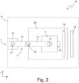
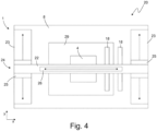
- the Figures 1 and 2 show a processing device 10 according to a first embodiment, while the Figures 3 and 4 show a processing device 20 according to a second embodiment.
- the first positioning device 1 is designed as a SCARA robot in the first embodiment and as a gantry robot in the second embodiment.
- the features that are present in both the first embodiment and the second embodiment will be discussed first.
- the processing device 10 will be discussed primarily; the explanations also apply to the processing device 20.
- the processing device 10 comprises a processing head 4, which has a processing unit 3.
- the processing unit 3 is designed as a tool and/or application unit, in particular as a printer unit.
- the processing device 10 further comprises a first positioning device 1 for moving the processing head 4 in order to position the processing unit 3 with a first accuracy at a predetermined processing position 33.
- the processing head 4 has a second positioning device 2.
- the processing device 10 is designed to position the processing unit 3 at the predetermined processing position 33 with a second accuracy using the second positioning device 2.
- the second accuracy is higher than the first accuracy, so that the lower accuracy of the first positioning device 1 is compensated by positioning with the second positioning device 2.
- the positioning error caused by positioning with the first positioning device 1 - i.e. the deviation between the position of the processing unit 3 and the specified processing position 33 - can be corrected by positioning with the second positioning device 2.
- a high level of accuracy can be achieved overall without the first positioning device 1, which positions the processing head 4 and thus generally has the larger positioning range, having to provide this high level of accuracy. Consequently, a positioning device with a large positioning range can also be used as the first positioning device 1, without thereby impairing the overall positioning accuracy of the processing device 10.
- the first positioning device 1 serves to move the machining head 4 relative to a static part of the machining device 10, for example a workpiece support 8, and/or relative to a workpiece 29.
- the first positioning device 1 has, for example, a first degree of freedom x and a second degree of freedom y for positioning the processing unit 3.
- the degrees of freedom x, y of the first positioning device 1 are linear degrees of freedom, in particular coordinates of a Cartesian coordinate system.
- a positioning plane is spanned by the two degrees of freedom x, y.
- the processing head 4 and/or the processing unit 3 can be positioned in particular in the positioning plane spanned by the degrees of freedom x, y.
- the processing device 10 has the workpiece support 8, on which the workpiece 29 is expediently arranged.
- the upper side of the workpiece support 8 and/or the upper side of the workpiece 29 is expediently aligned parallel to the positioning plane and in particular lies in the positioning plane or represents it.
- the first positioning device 1 can also be designed to move the processing head 4 in the z-direction - i.e. orthogonally to the x-direction and y-direction.
- the first positioning device 1 can thus be designed in particular to guide the processing head 4 in three-dimensional space.
- the first positioning device 1 expediently has several machine axes, in particular one or more linear machine axes and/or one or more rotational axes.
- the processing device 10 is designed in particular to position the processing unit 3 in an area using the first positioning device 1, within which a deviation from the predetermined processing position 33 can be corrected using the second positioning device 2. This area, in which a correction is possible using the second positioning device, can also be referred to as a processing window.
- the processing device 10 is expediently designed to recognize when the processing unit 3 leaves the processing window and in this case to abort or pause the processing by the processing unit 3.
- the first positioning device 1 is designed as a Scara robot.
- the first positioning device 1 accordingly comprises a robot base 31 on which a robot arm 11 is provided.
- the processing head 4 is attached or suspended at a distal end of the robot arm 11.
- the processing head 4 can be moved relative to the robot base 31 by means of the robot arm 11.
- the robot arm 11 has a first robot link 12 and a second robot link 14.
- the robot arm 11 can expediently also have further robot links.
- the processing head 4 is preferably attached to the last robot link - here the second robot link 14.
- the first robot member 12 is connected to the robot base 31 via a first machine axis 15 and can be driven relative to the robot base 31 via this first machine axis 15.
- the second robot member 14 is connected to the first robot member 12 via a second machine axis 16 and can be driven relative to the first robot member 12 via this second machine axis 16.
- the processing head 4 is connected to the second robot member 16 via a third machine axis 17 and can be driven relative to the second robot member 16 via this third machine axis 17.
- the second robot member 16 has a mechanical interface 7 to which the processing head 4 is attached, in particular in a removably manner.
- the first machine axis 15 and the second machine axis 16 expediently allow rotary movements, while the third machine axis 17 allows a rotary and a linear movement.
- a positioning device 1 designed in this way can position the processing head 4 in the x-direction, y-direction and z-direction.
- the robot base 31 is mechanically connected to the workpiece support 8; for example, the robot base 31 is arranged on the workpiece support 8 and extends upwards in the z-direction.
- the robot arm 11 extends essentially horizontally from the robot base 31 and protrudes over the x-y area of the workpiece support 8.
- the processing head 4 is suspended from the robot arm 11 and extends accordingly downwards in the z-direction to the workpiece support 8 or the workpiece 29.
- the first positioning device 1 is designed as a gantry robot, for example.
- the first positioning device 1 accordingly comprises a gantry carriage 24 that can be driven relative to the workpiece support 8 or relative to the workpiece 29.
- the gantry carriage 24 can be moved in the y-direction relative to the workpiece support 8 or relative to the workpiece 29.
- a first linear drive 23 is provided to drive the gantry carriage 24.
- the gantry carriage 24 has a gantry arm 22, on which the processing head 4 is suspended so that it can move, in particular in the x-direction.
- a second linear drive 26 is expediently provided on the gantry arm 22.
- a mechanical interface 7 is expediently provided on the gantry arm 22, to which the processing head 4 is attached, in particular in a detachable manner.
- the positioning device 1 designed as a gantry robot can position the processing head 4 in the x-direction and y-direction.
- the positioning device 1 can also be designed to position the processing head in the z-direction.
- the portal slide 24 has two vertical elements 25 which extend in the z-direction extend upwards from the workpiece support 8.
- the portal arm 22 extends from one vertical element 25 to the other vertical element 25 and together with the vertical elements 25 forms the portal carriage 24.
- the first positioning device 1 is not limited to the above-discussed embodiments as a Scara robot or gantry robot. Instead, the first positioning device 1 can also be designed as another robot device.
- the first positioning device 1 is expediently designed as an articulated arm robot, a robot with linear axes, a rail vehicle, a device traveling on a workpiece, and/or a traction system with ropes and/or chains.
- the positioning device 1 is expediently an industrial robot.
- the processing device 10 is designed, by way of example, to compensate for the lower accuracy of the first positioning device 1 in the first degree of freedom x and/or the second degree of freedom y by using the second positioning device 2.
- the second positioning device 2 expediently has the same degree of freedom x and/or the same degree of freedom y as the first positioning device 1.
- the second positioning device 2 can in particular correct a positioning error caused by the lower accuracy of the first positioning device 1 - that is, a deviation of the processing unit 3 from the predetermined processing position 33 in the x direction and/or y direction.
- the second positioning device 2 expediently has one, several or all of the degrees of freedom of the first positioning device 1.
- the second positioning device 2 preferably has an xy drive 27, for example a positioning platform, with which the processing unit 3 can be positioned relative to the processing head 4 in the x direction and in the y direction.
- the positioning device 2 also has a z drive 28, with which the processing unit 3 can be positioned relative to the processing head 4 in the z direction.
- the second positioning device 2 is preferably integrated in the processing head 4 or attached to it.
- the area, in particular the x-y area, in which the first positioning device 1 can position the processing unit 3 should also be referred to as the first positioning area.
- the area, in particular the x-y area, in which the second positioning device 2 can position the processing unit 3 should also be referred to as the second positioning area.
- the first positioning area is expediently larger than the second positioning area.
- the first positioning area is at least twice, in particular at least 10 times, expediently at least 50 times or 100 times larger than the second positioning area.
- the first positioning device 1 and the second positioning device 2 are preferably designed such that the first positioning area and the second positioning area always overlap.
- the second positioning device 2 is in particular designed such that the positioning of the processing unit 3 by the second positioning device 2 takes place with a higher accuracy and/or speed and/or rigidity than the positioning of the processing unit 3 with the first positioning device 1.
- the processing head 4 is designed as a manually operable processing device, so that the processing head 4 can be manually positioned at the predetermined processing position 33, in particular when removed from the first positioning device 1 or the processing device 10.
- the processing head 4 is designed to position the processing unit 3 at the predetermined processing position 33 with the second accuracy using the second positioning device 2, so that a lower accuracy of the manual positioning is compensated for by positioning with the second positioning device 2.
- the processing head 4 can therefore expediently be handled as an independent processing device and used to process the workpiece 29.
- the processing unit 3 designed as a tool expediently comprises a router, a saw, in particular a circular saw and/or jigsaw, a laser, a punching device, a cutting tool, in particular a textile and/or leather cutter, and/or a water jet. If the processing unit 3 is designed as an application unit, it comprises in particular a printing unit, expediently a 3D printing unit.
- the processing device 10 in particular the first positioning device 1, has a mechanical interface 7 to which the processing head 4 and/or the processing unit 3 is removably attached.
- the mechanical interface 7 can in particular be designed as a changing device with which a change of the processing head 4 and/or the processing unit 3 is possible.
- the processing head 4 - and thus in particular also the second positioning device 2 - can be firmly connected to the first positioning device 1.
- the processing device 10, in particular the first positioning device 1, can also have a lifting means, in particular a gripper and/or a vacuum suction device, for handling the processing head 4, the processing unit 3 and/or a workpiece 29.
- the lifting means can expediently represent the mechanical interface 7 mentioned above.
- one and the same lifting means can be used to fasten the processing head 4 to the first positioning device 1 during processing and to transport the workpiece 29 into or out of the processing area of the processing device 10 before and/or after processing.
- the processing device 10 is designed to position the workpiece 29 on the workpiece support 8 with the aid of the lifting means.
- the processing device 10 can expediently also comprise a change magazine for receiving at least one further processing head and/or at least one further processing unit.
- the processing device 10 has at least two different processing heads and/or two different processing units and is designed to replace the processing head 4 attached to the first positioning device 1 and/or the processing unit 3 with another processing head and/or another processing unit using the change magazine.
- the processing device 10 is designed as an example, the position of the processing unit 3 relative to the predetermined To determine the processing position 33 and to carry out the positioning of the processing unit 3 using the first positioning device and/or the second positioning device 2 based on the determined position of the processing unit 3.
- the processing device 10 is designed to recognize the processing unit 3 and/or the workpiece 29, in particular by means of a video and/or image recording, a laser scan and/or by means of ultrasound and to calculate the current position of the processing unit 3 using a position determination algorithm. On the basis of the calculated position, the further positioning or correction of the positioning can then take place with one or both of the positioning devices 1, 2, in particular with the second positioning device 2.
- the processing device 10 has, for example, a sensor unit 19, for example an image sensor, arranged in particular on the processing head 4.
- the sensor unit 19 is designed to detect a reference element 18 present on the processing device 10 and/or the workpiece 29.
- the reference element 18 is, for example, an optical marking, in particular a piece of tape, preferably a piece of adhesive tape, with a pattern printed on it.
- the reference element 18 can also be provided only on the processing device 1, for example on the workpiece support 8, and thus in particular not on the workpiece 29.
- features of the workpiece 29, for example edges, films and/or markers applied to the workpiece 29, markings applied next to and/or above the workpiece 29 on the workpiece support 8 or markings positioned in the positioning area of the first positioning device 1 or the processing device 10 (e.g. by means of stands), in particular circular markers and/or rulers, can serve as the reference element 18.
- a ruler positioned next to and/or on the workpiece 29 can expediently serve as the reference element 18.
- the sensor unit 19 can also comprise other position sensors, in particular an acceleration sensor, a laser sensor and/or an ultrasonic sensor.
- a laser and/or ultrasound source can be provided on the processing device 10, in particular on the processing head 4.
- the processing device 10 is expediently designed to determine the position of the processing unit 3 relative to the predetermined processing position 33 using the sensor unit 19.
- the processing device 10 expediently has a stored reference map in which the position of the reference element 18 is specified.
- the processing device 10 is designed to determine the position of the processing unit 3, in particular relative to the predetermined processing position 33, using the reference map and the reference element 18 detected by the sensor unit 19.
- the sensor unit 19, as mentioned above, is an image sensor and the reference element 18 is an optical marking.
- the processing device 10 is in particular designed to recognize the reference element 18 in an image recorded by the sensor unit 19 using image processing software, for example using an algorithm for machine vision, and to calculate a relative position of the sensor unit 19 or the processing unit 3 to the reference element 18 based on the recognized reference element 18. Since the position of the reference element 18 in the reference map is known, the position of the processing unit 3 in the reference map can be determined.
- a deviation of the position of the processing unit 3 from the predetermined processing position 33 can be determined, on the basis of which the positioning with the second positioning device 2 can be carried out in order to compensate for this deviation.
- the processing device 10 is designed to create the reference map as part of an initialization process.
- the processing device 10 is designed, for example, to move the processing head 4 using the first positioning device 1 in order to detect the processing area of the processing device 10 with the sensor unit 19, in particular image data of it.
- the processing device 10 is in particular designed to create the reference map based on the detected processing area, in particular on the basis of the recorded image data.
- the explained position determination of the processing unit 3 is expediently used only when positioning with the second positioning device 2 - i.e. in particular not when positioning with the first positioning device 1.
- the positioning with the first positioning device 1 can therefore be a mere control - i.e. not a regulation.
- the processing device 10 is therefore designed in particular to carry out the positioning with the first positioning device 1 as part of a control. This can mean, for example, that no feedback variable about the position of the processing head 4 or the processing unit 3 is used during positioning with the first positioning device 1.
- the positioning with the second positioning device 2 preferably takes place as a control.
- the processing device 10 is expediently designed to carry out the positioning with the second positioning device 2 as part of a control.
- the processing device 10 is designed to regulate the position of the processing unit 3 to the predetermined processing position 33.
- the processing device 10 can use a feedback variable about the position of the processing head 4 or the processing unit 3 during positioning with the second positioning device 2, for example the position of the processing unit 3 detected by the sensor unit 19.
- the processing device 10 has one or more control units, in particular computer units such as microcontrollers, in order to carry out the above-discussed determination of the position of the processing unit 3 and/or control of the processing unit 3 and/or control of the positioning devices 1, 2.
- the positioning devices 1, 2 are controlled in particular on the basis of processing data, which are provided, for example, as design/CAD data.
- the processing device 10 has a control unit, for example a microcontroller, which controls both the first positioning device 1 and the second positioning device 2.
- This control unit expediently also carries out coordination between the two positioning devices 1, 2.
- this control unit can also be designed to control or communicate with the processing unit 3 and/or the sensor unit 19.
- the processing device 10 comprises a separate control unit for each positioning device 1, 2.
- the processing device 10 has a first control unit 5 for controlling the first positioning device 1 and a second control unit 6 for controlling the second positioning device 2.
- the second control unit 6 is part of the processing head 4.
- the first control unit 5 does not control the second positioning device 2 and the second control unit 6 preferably does not control the first positioning device 1.
- Each control unit 5, 6 is preferably only responsible for one positioning device.
- the first control unit 5 and/or the second control unit 6 is designed to control the processing unit 3 in order to effect, for example, a processing of the workpiece 29.
- the first control unit 5 and/or the second control unit 6 are expediently connected to the first positioning device 1, the second positioning device 2, the processing unit 3 and/or the sensor unit 19 via wired and/or wireless data connections.
- Processing data from which in particular the aforementioned processing position 33 emerges, are expediently provided in both control units 5, 6, so that each of the control units 5, 6 can control the respectively assigned positioning device 1, 2 on the basis of the processing data.
- the control units 5, 6 can be designed differently so that they accept and/or require the processing data in different data formats.
- the processing device 10 is expediently designed to provide the first control unit 5 with processing data that define the processing position 33 in a first data format and to provide the second control unit 6 with the processing data in a second data format.
- the second data format expediently differs from the first data format.
- the first data format is a G-code data format and the second data format is a vector data format, in particular SVG.
- the first control unit 5 is designed to provide the processing data to the second control unit 6 in the second data format and/or the second control unit 6 is designed to provide the processing data to the first control unit 5 in the first data format.
- the control units 5, 6 can be designed to create and/or receive the processing data in one of the data formats, create the processing data in the other of the data formats, receive it and/or convert it into the other data format and provide the processing data in the other data format to the other control unit 5, 6.
- the processing device 10, in particular the processing head 4 can, for example, have an input device with which a user can manually enter processing data, for example in the form of one or more processing positions, into the second control unit 6.
- the processing data are then optionally converted by the second control unit 6 into the format required by the first control unit 5 and provided to the first control unit 5.
- first control unit 5 and the second control unit 6 may have processing data with different data content.
- first control unit 5 may have less precise processing data than the second control unit 6.
- first control unit 5 may be designed to control the first positioning device 1 on the basis of processing data that have a lower spatial resolution than the processing data with which the second control unit 6 controls the second positioning device 2.
- control units 5, 6 accept/require the processing data in the same data format and/or with the same data content.
- control units 5, 6 each of which controls one of the positioning devices 5, 6, it can be advantageous to carry out a position comparison between the two control units 5, 6.
- the processing device 10 is expediently designed to provide position information to the first control unit 5 and/or the second control unit 6 in order to carry out a position comparison between the first control unit 5 and the second control unit 6.
- One or both of the control units 5, 6 is expediently designed to create the position information and provide it to the other control unit 5, 6.
- the position information can in particular indicate that one of the positioning devices 1, 2 is in a specific position, for example that the processing head 4 and/or the processing unit 3 are at a zero position and/or a limit of one or both of the positioning areas.
- a time comparison for example for the purpose of temporal synchronization, can also be carried out between the two control units 5, 6.
- the processing device 10 is preferably designed to provide time information to the first control unit 5 and/or the second control unit 6 in order to carry out a time comparison between the first control unit 5 and the second control unit 6.
- One or both of the control units 5, 6 are expediently designed to create the time information and provide it to the other control unit 5, 6.
Landscapes
- Engineering & Computer Science (AREA)
- Mechanical Engineering (AREA)
- Robotics (AREA)
- Health & Medical Sciences (AREA)
- General Health & Medical Sciences (AREA)
- Orthopedic Medicine & Surgery (AREA)
- Manipulator (AREA)
- Numerical Control (AREA)
- Automatic Control Of Machine Tools (AREA)
Claims (14)
- Dispositif d'usinage (10 ; 20) avec une tête d'usinage (4), qui comprend une unité d'usinage (3) réalisée en tant qu'outil et/ou qu'unité d'application, en particulier en tant qu'unité d'impression, et un premier système de positionnement (1) destiné à déplacer la tête d'usinage (4) pour positionner l'unité d'usinage (3) avec une première précision sur une position d'usinage (33) prédéfinie, dans lequel la tête d'usinage (4) dispose d'un deuxième système de positionnement (2) et le dispositif d'usinage (10 ; 20) est réalisé pour positionner, en utilisant le deuxième système de positionnement (2), l'unité d'usinage (3) avec une deuxième précision sur la position d'usinage (33) prédéfinie, dans lequel la deuxième précision est plus élevée que la première précision de telle sorte que la faible précision du premier système de positionnement (2) est compensée par le positionnement avec le deuxième système de positionnement (2), caractérisé en ce que la tête d'usinage (4) est réalisée en tant qu'appareil d'usinage pouvant être manipulé manuellement de telle sorte que la tête d'usinage (4) peut être positionnée manuellement sur la position d'usinage (33) prédéfinie dans un état retiré du premier système de positionnement (1) et la tête de positionnement (4) est réalisée pour positionner, en utilisant le deuxième système de positionnement (2), l'unité d'usinage (3) avec la deuxième précision sur la position d'usinage (33) prédéfinie de telle sorte qu'une faible précision du positionnement manuel est compensée par le positionnement avec le deuxième système de positionnement (2).
- Dispositif d'usinage (10 ; 20) selon la revendication 1,
caractérisé en ce que le dispositif d'usinage (10 ; 20) dispose d'une première unité de commande (5) destinée à piloter le premier système de positionnement (1) et d'une deuxième unité de commande (6) destinée à piloter le deuxième système de positionnement (2). - Dispositif d'usinage (10 ; 20) selon la revendication 2,
caractérisé en ce que le dispositif d'usinage (10 ; 20) est réalisé pour fournir à la première unité de commande (5) des données d'usinage définissant la position d'usinage (33) dans un premier format de données et pour fournir à la deuxième unité de commande (6) les données d'usinage dans un deuxième format de données. - Dispositif d'usinage (10 ; 20) selon la revendication 2 ou 3, caractérisé en ce que le dispositif d'usinage (10 ; 20) est réalisé pour fournir à la première unité de commande (5) et/ou à la deuxième unité de commande (6) une information de position pour mettre en oeuvre une comparaison de positions entre la première unité de commande (5) et la deuxième unité de commande (6).
- Dispositif d'usinage (10 ; 20) selon l'une quelconque des revendications 2 à 4, caractérisé en ce que le dispositif d'usinage (10 ; 20) est réalisé pour fournir à la première unité de commande (5) et/ou à la deuxième unité de commande (6) une information de temps pour mettre en oeuvre une comparaison temporelle entre la première unité de commande (5) et la deuxième unité de commande (6).
- Dispositif d'usinage (10 ; 20) selon l'une quelconque des revendications précédentes, caractérisé en ce que le dispositif d'usinage (10) est réalisé pour mettre en oeuvre le positionnement avec le premier système de positionnement (1) dans le cadre d'une commande et pour mettre en oeuvre le positionnement avec le deuxième système de positionnement dans le cadre d'une régulation.
- Dispositif d'usinage (10 ; 20) selon l'une quelconque des revendications précédentes, caractérisé en ce que le premier système de positionnement (1) dispose d'un premier degré de liberté (x) et/ou d'un deuxième degré de liberté (y) pour positionner l'unité d'usinage (3), et le dispositif d'usinage (10 ; 20) est réalisé pour compenser, en utilisant le deuxième système de positionnement (2), la faible précision du premier système de positionnement (1) dans le premier degré de liberté (x) et/ou le deuxième degré de liberté (y).
- Dispositif d'usinage (10 ; 20) selon la revendication précédente, caractérisé en ce que le dispositif d'usinage (10) est réalisé pour définir la position de l'unité d'usinage (3) par rapport à la position d'usinage (33) prédéfinie et pour mettre en oeuvre le positionnement de l'unité d'usinage (3) en utilisant le premier système de positionnement et/ou le deuxième système de positionnement (2) sur la base de la position définie de l'unité d'usinage (3).
- Dispositif d'usinage (10 ; 20) selon la revendication 8,
caractérisé en ce que le dispositif d'usinage (10) dispose d'une unité de capteur (19) disposée en particulier sur la tête d'usinage (4), en particulier d'un capteur d'image, pour détecter un élément de référence (18) présent sur le dispositif d'usinage (10 ; 20) et/ou sur une pièce (29), en particulier d'un marquage optique et est réalisé pour définir la position de l'unité d'usinage (3) par rapport à la position d'usinage (33) prédéfinie en utilisant l'unité de capteur (19). - Dispositif d'usinage (10 ; 20) selon l'une quelconque des revendications précédentes, caractérisé en ce que le premier système de positionnement (1) comprend un dispositif robotisé, un robot industriel, un robot sur portique, un robot de type SCARA, un robot à bras articulé, un robot avec des axes linéaires, un véhicule sur rails, un appareil se déplaçant sur une pièce et/ou un système de traction avec des câbles et/ou des chaînes.
- Dispositif d'usinage (10 ; 20) selon l'une quelconque des revendications précédentes, caractérisé en ce que l'outil comprend une fraise supérieure, une scie, en particulier une scie circulaire et/ou une scie sauteuse, un laser, un système d'estampage, un outil de découpe, en particulier un cutter pour textile et/ou cuir, et/ou un système à jets d'eau et/ou l'unité d'application comprend une unité d'impression, de manière opportune une unité d'impression 3D.
- Dispositif d'usinage (10 ; 20) selon l'une quelconque des revendications précédentes, caractérisé en ce que le dispositif d'usinage (10 ; 20), en particulier le premier système de positionnement (1), dispose d'une interface mécanique (7), sur laquelle la tête d'usinage (4) et/ou l'unité d'usinage (3) peuvent être installées de manière à pouvoir être retirées.
- Dispositif d'usinage (10 ; 20) selon l'une quelconque des revendications précédentes, caractérisé en ce que le dispositif d'usinage (10 ; 20), en particulier le premier système de positionnement (1), dispose d'un moyen de levage, en particulier d'un grappin et/ou d'un système d'aspiration sous vide, destiné à manipuler la tête d'usinage (4), l'unité d'usinage (3) et/ou une pièce (29).
- Dispositif d'usinage (10 ; 20) selon l'une quelconque des revendications précédentes, caractérisé en ce que le dispositif d'usinage (10 ; 20) dispose d'un magasin de remplacement destiné à recevoir au moins une autre tête d'usinage et/ou au moins une autre unité d'usinage.
Applications Claiming Priority (2)
| Application Number | Priority Date | Filing Date | Title |
|---|---|---|---|
| DE102018200551.6A DE102018200551A1 (de) | 2018-01-15 | 2018-01-15 | Bearbeitungsvorrichtung |
| PCT/EP2018/083520 WO2019137695A1 (fr) | 2018-01-15 | 2018-12-04 | Arrangement d'usinage |
Publications (2)
| Publication Number | Publication Date |
|---|---|
| EP3710198A1 EP3710198A1 (fr) | 2020-09-23 |
| EP3710198B1 true EP3710198B1 (fr) | 2024-10-02 |
Family
ID=64664257
Family Applications (1)
| Application Number | Title | Priority Date | Filing Date |
|---|---|---|---|
| EP18815989.1A Active EP3710198B1 (fr) | 2018-01-15 | 2018-12-04 | Arrangement d'usinage |
Country Status (5)
| Country | Link |
|---|---|
| US (1) | US11667032B2 (fr) |
| EP (1) | EP3710198B1 (fr) |
| CN (1) | CN111565886B (fr) |
| DE (1) | DE102018200551A1 (fr) |
| WO (1) | WO2019137695A1 (fr) |
Families Citing this family (4)
| Publication number | Priority date | Publication date | Assignee | Title |
|---|---|---|---|---|
| CN116442210B (zh) * | 2022-01-10 | 2024-12-06 | 腾讯科技(深圳)有限公司 | 冗余机器人运动控制方法以及冗余机器人 |
| DE102022101741A1 (de) | 2022-01-26 | 2023-07-27 | Schaeffler Technologies AG & Co. KG | Stanzvorrichtung |
| KR102780717B1 (ko) * | 2022-11-30 | 2025-03-12 | 주식회사 씨엔 | 스카라 로봇 |
| DE102023118134B3 (de) | 2023-07-10 | 2025-01-09 | Dr. Ing. H.C. F. Porsche Aktiengesellschaft | Schneidbearbeitungsanordnung zur Bearbeitung von einem Blechteil und Verfahren |
Family Cites Families (15)
| Publication number | Priority date | Publication date | Assignee | Title |
|---|---|---|---|---|
| JPS5485678A (en) | 1977-12-20 | 1979-07-07 | Canon Inc | High accuracy alignment method for air bearing guide system xy stage |
| US4812666A (en) * | 1987-09-17 | 1989-03-14 | Universal Instruments Corporation | Position feedback enhancement over a limited repositioning area for a moveable member |
| JPH07128467A (ja) | 1993-11-02 | 1995-05-19 | Canon Inc | 微動駆動担体 |
| DE10230021C1 (de) * | 2002-07-04 | 2003-07-10 | Daimler Chrysler Ag | Verfahren zum Reinigen eines Bauteils und geeignete Reinigungsvorrichtung |
| JP4577107B2 (ja) * | 2005-06-17 | 2010-11-10 | 三菱電機株式会社 | 機械位置制御装置 |
| KR100676825B1 (ko) * | 2005-10-14 | 2007-02-01 | 삼성전자주식회사 | 작업용 기계장치 및 기계장치용 작업공구 |
| DE102006049627A1 (de) * | 2006-10-20 | 2008-04-24 | Fraunhofer-Gesellschaft zur Förderung der angewandten Forschung e.V. | Verfahren und Vorrichtung zur Feinpositionierung eines Werkzeugs mit einer Handhabungseinrichtung |
| DE102007028934A1 (de) * | 2007-06-22 | 2008-12-24 | Trumpf Werkzeugmaschinen Gmbh + Co. Kg | Verfahren zur optimierten Bewegungskoordination von Mess-oder Werkzeugmaschinen mit redundanten translatorisch wirksamen Achsen |
| JP5031459B2 (ja) * | 2007-06-27 | 2012-09-19 | 株式会社アルバック | 粗微移動装置及びそれを備えた液体供給装置 |
| CN201573076U (zh) * | 2009-11-19 | 2010-09-08 | 昆山昆得精密电子科技有限公司 | 刀具微调装置 |
| DE102011006679B4 (de) * | 2011-03-16 | 2018-07-12 | Ferrobotics Compliant Robot Technology Gmbh | Aktive Handhabungsvorrichtung und Verfahren für Kontaktaufgaben |
| CN202684742U (zh) * | 2012-06-28 | 2013-01-23 | 无锡市海鸿精工机械制造有限公司 | 磨床的进给机构 |
| WO2015087411A1 (fr) | 2013-12-11 | 2015-06-18 | 住友化学株式会社 | Appareil de traitement et procédé de traitement |
| AT519718B1 (de) * | 2017-02-28 | 2018-12-15 | Fill Gmbh | Knickarmroboter und Verfahren zum spanenden Bearbeiten eines Werkstückes mittels dem Knickarmroboter |
| US10513856B2 (en) * | 2017-03-31 | 2019-12-24 | Canvas Construction, Inc. | Automated drywall planning system and method |
-
2018
- 2018-01-15 DE DE102018200551.6A patent/DE102018200551A1/de not_active Withdrawn
- 2018-12-04 EP EP18815989.1A patent/EP3710198B1/fr active Active
- 2018-12-04 WO PCT/EP2018/083520 patent/WO2019137695A1/fr not_active Ceased
- 2018-12-04 US US16/961,950 patent/US11667032B2/en active Active
- 2018-12-04 CN CN201880086611.9A patent/CN111565886B/zh active Active
Also Published As
| Publication number | Publication date |
|---|---|
| CN111565886B (zh) | 2022-07-19 |
| WO2019137695A1 (fr) | 2019-07-18 |
| US20200384641A1 (en) | 2020-12-10 |
| US11667032B2 (en) | 2023-06-06 |
| DE102018200551A1 (de) | 2019-07-18 |
| CN111565886A (zh) | 2020-08-21 |
| EP3710198A1 (fr) | 2020-09-23 |
Similar Documents
| Publication | Publication Date | Title |
|---|---|---|
| DE102018112820B4 (de) | Teach-Positionskorrekturvorrichtung und Teach-Positionskorrekturverfahren | |
| EP3710198B1 (fr) | Arrangement d'usinage | |
| EP1966661B1 (fr) | Procede et dispositif pour etablir une trajectoire de robot | |
| DE102009014766B4 (de) | Überlagerte Achsen bei einer Vorrichtung zur Bearbeitung eines Werkstücks mit einem Werkzeug | |
| DE102016115987A1 (de) | Koordinatensystemeinstellungsverfahren, koordinatensystemeinstellungsvorrichtung und robotersystem mit koordinatensystemeinstellungsvorrichtung | |
| EP2012208B1 (fr) | Outil manuel de programmation | |
| EP3147086A1 (fr) | Automatisation d'operations de robot | |
| DE602006000541T2 (de) | Servosteuervorrichtung und Verfahren zur Einstellung eines Servosystems | |
| DE112021000584T5 (de) | Steuervorrichtung für Roboter, Robotersystem, Kontrollverfahren und Programm | |
| DE102007019453B4 (de) | Koordinatenmessgerät mit zwei Schlitten auf gemeinsamer Führung | |
| DE102020119550B4 (de) | Vorrichtung, Robotersteuereinrichtung, Robotersystem und Verfahren zum Einstellen eines Roboterkoordinatensystems | |
| EP1172183A2 (fr) | Dispositif et appareil de génération de données de déplacement corrigées pour un déplacement prédéfini d'un dispositif mobile, dispositif mobile et système composé de dispositifs mobiles | |
| WO2017063636A1 (fr) | Dispositif et procédé d'usinage par laser d'une pièce réalisée sous forme de composant d'armoire de commande | |
| DE102021128336A1 (de) | System und Verfahren zum Kalibrieren und/oder Regeln einer beweglichen Mehrgelenkkinematik | |
| DE102007058293A1 (de) | Kalibriervorrichtung und Verfahren zum Abgleichen eines Roboterkoordinatensystems | |
| DE10302592A1 (de) | Verfahren und Vorrichtung zum Betreiben eines Arbeitsroboters | |
| EP3541586A1 (fr) | Procédé et commande de robot pour établir une trajectoire d'un robot | |
| EP3083159B1 (fr) | Dispositif de positionnement | |
| EP3996855B1 (fr) | Procédé de positionnement d'un dispositif d'actionnement par rapport à une machine de cintrage | |
| DE102013210739B3 (de) | Koordinatenmessgerät und Verfahren zur Vermessung eines Werkstücks mit einer selbstfahrenden Antriebseinheit und einer fahrbaren Messeinheit | |
| DE102009034938B4 (de) | Verfahren zur Kommandierung eines Bewegungssystems mit einer Messeinrichtung | |
| WO2017181208A1 (fr) | Barre de pliage pour plieuse pivotante | |
| DE102011084353B4 (de) | Verfahren und Computerprogramm zum Einrichten eines Greifroboters, sowie Greifroboter | |
| DE102022213568B3 (de) | Kalibrieren einer Steuerung | |
| DE112022005801T5 (de) | Arbeitsrobotersystem |
Legal Events
| Date | Code | Title | Description |
|---|---|---|---|
| STAA | Information on the status of an ep patent application or granted ep patent |
Free format text: STATUS: UNKNOWN |
|
| STAA | Information on the status of an ep patent application or granted ep patent |
Free format text: STATUS: THE INTERNATIONAL PUBLICATION HAS BEEN MADE |
|
| PUAI | Public reference made under article 153(3) epc to a published international application that has entered the european phase |
Free format text: ORIGINAL CODE: 0009012 |
|
| STAA | Information on the status of an ep patent application or granted ep patent |
Free format text: STATUS: REQUEST FOR EXAMINATION WAS MADE |
|
| 17P | Request for examination filed |
Effective date: 20200615 |
|
| AK | Designated contracting states |
Kind code of ref document: A1 Designated state(s): AL AT BE BG CH CY CZ DE DK EE ES FI FR GB GR HR HU IE IS IT LI LT LU LV MC MK MT NL NO PL PT RO RS SE SI SK SM TR |
|
| AX | Request for extension of the european patent |
Extension state: BA ME |
|
| RIN1 | Information on inventor provided before grant (corrected) |
Inventor name: DAGEFOERDE, JONAS |
|
| DAV | Request for validation of the european patent (deleted) | ||
| DAX | Request for extension of the european patent (deleted) | ||
| STAA | Information on the status of an ep patent application or granted ep patent |
Free format text: STATUS: EXAMINATION IS IN PROGRESS |
|
| 17Q | First examination report despatched |
Effective date: 20221028 |
|
| P01 | Opt-out of the competence of the unified patent court (upc) registered |
Effective date: 20230519 |
|
| GRAP | Despatch of communication of intention to grant a patent |
Free format text: ORIGINAL CODE: EPIDOSNIGR1 |
|
| STAA | Information on the status of an ep patent application or granted ep patent |
Free format text: STATUS: GRANT OF PATENT IS INTENDED |
|
| INTG | Intention to grant announced |
Effective date: 20240422 |
|
| GRAS | Grant fee paid |
Free format text: ORIGINAL CODE: EPIDOSNIGR3 |
|
| GRAA | (expected) grant |
Free format text: ORIGINAL CODE: 0009210 |
|
| STAA | Information on the status of an ep patent application or granted ep patent |
Free format text: STATUS: THE PATENT HAS BEEN GRANTED |
|
| AK | Designated contracting states |
Kind code of ref document: B1 Designated state(s): AL AT BE BG CH CY CZ DE DK EE ES FI FR GB GR HR HU IE IS IT LI LT LU LV MC MK MT NL NO PL PT RO RS SE SI SK SM TR |
|
| REG | Reference to a national code |
Ref country code: GB Ref legal event code: FG4D Free format text: NOT ENGLISH |
|
| REG | Reference to a national code |
Ref country code: CH Ref legal event code: EP |
|
| REG | Reference to a national code |
Ref country code: IE Ref legal event code: FG4D Free format text: LANGUAGE OF EP DOCUMENT: GERMAN |
|
| REG | Reference to a national code |
Ref country code: DE Ref legal event code: R096 Ref document number: 502018015191 Country of ref document: DE |
|
| REG | Reference to a national code |
Ref country code: LT Ref legal event code: MG9D |
|
| REG | Reference to a national code |
Ref country code: NL Ref legal event code: MP Effective date: 20241002 |
|
| PG25 | Lapsed in a contracting state [announced via postgrant information from national office to epo] |
Ref country code: NL Free format text: LAPSE BECAUSE OF FAILURE TO SUBMIT A TRANSLATION OF THE DESCRIPTION OR TO PAY THE FEE WITHIN THE PRESCRIBED TIME-LIMIT Effective date: 20241002 |
|
| PG25 | Lapsed in a contracting state [announced via postgrant information from national office to epo] |
Ref country code: NL Free format text: LAPSE BECAUSE OF FAILURE TO SUBMIT A TRANSLATION OF THE DESCRIPTION OR TO PAY THE FEE WITHIN THE PRESCRIBED TIME-LIMIT Effective date: 20241002 |
|
| PG25 | Lapsed in a contracting state [announced via postgrant information from national office to epo] |
Ref country code: IS Free format text: LAPSE BECAUSE OF FAILURE TO SUBMIT A TRANSLATION OF THE DESCRIPTION OR TO PAY THE FEE WITHIN THE PRESCRIBED TIME-LIMIT Effective date: 20250202 Ref country code: PT Free format text: LAPSE BECAUSE OF FAILURE TO SUBMIT A TRANSLATION OF THE DESCRIPTION OR TO PAY THE FEE WITHIN THE PRESCRIBED TIME-LIMIT Effective date: 20250203 Ref country code: HR Free format text: LAPSE BECAUSE OF FAILURE TO SUBMIT A TRANSLATION OF THE DESCRIPTION OR TO PAY THE FEE WITHIN THE PRESCRIBED TIME-LIMIT Effective date: 20241002 |
|
| PG25 | Lapsed in a contracting state [announced via postgrant information from national office to epo] |
Ref country code: FI Free format text: LAPSE BECAUSE OF FAILURE TO SUBMIT A TRANSLATION OF THE DESCRIPTION OR TO PAY THE FEE WITHIN THE PRESCRIBED TIME-LIMIT Effective date: 20241002 |
|
| PG25 | Lapsed in a contracting state [announced via postgrant information from national office to epo] |
Ref country code: BG Free format text: LAPSE BECAUSE OF FAILURE TO SUBMIT A TRANSLATION OF THE DESCRIPTION OR TO PAY THE FEE WITHIN THE PRESCRIBED TIME-LIMIT Effective date: 20241002 |
|
| PG25 | Lapsed in a contracting state [announced via postgrant information from national office to epo] |
Ref country code: ES Free format text: LAPSE BECAUSE OF FAILURE TO SUBMIT A TRANSLATION OF THE DESCRIPTION OR TO PAY THE FEE WITHIN THE PRESCRIBED TIME-LIMIT Effective date: 20241002 |
|
| PG25 | Lapsed in a contracting state [announced via postgrant information from national office to epo] |
Ref country code: NO Free format text: LAPSE BECAUSE OF FAILURE TO SUBMIT A TRANSLATION OF THE DESCRIPTION OR TO PAY THE FEE WITHIN THE PRESCRIBED TIME-LIMIT Effective date: 20250102 |
|
| PG25 | Lapsed in a contracting state [announced via postgrant information from national office to epo] |
Ref country code: LV Free format text: LAPSE BECAUSE OF FAILURE TO SUBMIT A TRANSLATION OF THE DESCRIPTION OR TO PAY THE FEE WITHIN THE PRESCRIBED TIME-LIMIT Effective date: 20241002 Ref country code: GR Free format text: LAPSE BECAUSE OF FAILURE TO SUBMIT A TRANSLATION OF THE DESCRIPTION OR TO PAY THE FEE WITHIN THE PRESCRIBED TIME-LIMIT Effective date: 20250103 |
|
| PG25 | Lapsed in a contracting state [announced via postgrant information from national office to epo] |
Ref country code: CZ Free format text: LAPSE BECAUSE OF FAILURE TO SUBMIT A TRANSLATION OF THE DESCRIPTION OR TO PAY THE FEE WITHIN THE PRESCRIBED TIME-LIMIT Effective date: 20241002 Ref country code: PL Free format text: LAPSE BECAUSE OF FAILURE TO SUBMIT A TRANSLATION OF THE DESCRIPTION OR TO PAY THE FEE WITHIN THE PRESCRIBED TIME-LIMIT Effective date: 20241002 |
|
| PG25 | Lapsed in a contracting state [announced via postgrant information from national office to epo] |
Ref country code: RS Free format text: LAPSE BECAUSE OF FAILURE TO SUBMIT A TRANSLATION OF THE DESCRIPTION OR TO PAY THE FEE WITHIN THE PRESCRIBED TIME-LIMIT Effective date: 20250102 |
|
| PG25 | Lapsed in a contracting state [announced via postgrant information from national office to epo] |
Ref country code: SM Free format text: LAPSE BECAUSE OF FAILURE TO SUBMIT A TRANSLATION OF THE DESCRIPTION OR TO PAY THE FEE WITHIN THE PRESCRIBED TIME-LIMIT Effective date: 20241002 |
|
| REG | Reference to a national code |
Ref country code: DE Ref legal event code: R097 Ref document number: 502018015191 Country of ref document: DE |
|
| PG25 | Lapsed in a contracting state [announced via postgrant information from national office to epo] |
Ref country code: MC Free format text: LAPSE BECAUSE OF FAILURE TO SUBMIT A TRANSLATION OF THE DESCRIPTION OR TO PAY THE FEE WITHIN THE PRESCRIBED TIME-LIMIT Effective date: 20241002 |
|
| PG25 | Lapsed in a contracting state [announced via postgrant information from national office to epo] |
Ref country code: DK Free format text: LAPSE BECAUSE OF FAILURE TO SUBMIT A TRANSLATION OF THE DESCRIPTION OR TO PAY THE FEE WITHIN THE PRESCRIBED TIME-LIMIT Effective date: 20241002 |
|
| PG25 | Lapsed in a contracting state [announced via postgrant information from national office to epo] |
Ref country code: EE Free format text: LAPSE BECAUSE OF FAILURE TO SUBMIT A TRANSLATION OF THE DESCRIPTION OR TO PAY THE FEE WITHIN THE PRESCRIBED TIME-LIMIT Effective date: 20241002 |
|
| PG25 | Lapsed in a contracting state [announced via postgrant information from national office to epo] |
Ref country code: RO Free format text: LAPSE BECAUSE OF FAILURE TO SUBMIT A TRANSLATION OF THE DESCRIPTION OR TO PAY THE FEE WITHIN THE PRESCRIBED TIME-LIMIT Effective date: 20241002 |
|
| PG25 | Lapsed in a contracting state [announced via postgrant information from national office to epo] |
Ref country code: SK Free format text: LAPSE BECAUSE OF FAILURE TO SUBMIT A TRANSLATION OF THE DESCRIPTION OR TO PAY THE FEE WITHIN THE PRESCRIBED TIME-LIMIT Effective date: 20241002 |
|
| PG25 | Lapsed in a contracting state [announced via postgrant information from national office to epo] |
Ref country code: IT Free format text: LAPSE BECAUSE OF FAILURE TO SUBMIT A TRANSLATION OF THE DESCRIPTION OR TO PAY THE FEE WITHIN THE PRESCRIBED TIME-LIMIT Effective date: 20241002 |
|
| REG | Reference to a national code |
Ref country code: CH Ref legal event code: PL |
|
| PLBE | No opposition filed within time limit |
Free format text: ORIGINAL CODE: 0009261 |
|
| STAA | Information on the status of an ep patent application or granted ep patent |
Free format text: STATUS: NO OPPOSITION FILED WITHIN TIME LIMIT |
|
| PG25 | Lapsed in a contracting state [announced via postgrant information from national office to epo] |
Ref country code: LU Free format text: LAPSE BECAUSE OF NON-PAYMENT OF DUE FEES Effective date: 20241204 |
|
| PG25 | Lapsed in a contracting state [announced via postgrant information from national office to epo] |
Ref country code: SE Free format text: LAPSE BECAUSE OF FAILURE TO SUBMIT A TRANSLATION OF THE DESCRIPTION OR TO PAY THE FEE WITHIN THE PRESCRIBED TIME-LIMIT Effective date: 20241002 |
|
| 26N | No opposition filed |
Effective date: 20250703 |
|
| REG | Reference to a national code |
Ref country code: BE Ref legal event code: MM Effective date: 20241231 |
|
| PG25 | Lapsed in a contracting state [announced via postgrant information from national office to epo] |
Ref country code: BE Free format text: LAPSE BECAUSE OF NON-PAYMENT OF DUE FEES Effective date: 20241231 |
|
| PG25 | Lapsed in a contracting state [announced via postgrant information from national office to epo] |
Ref country code: CH Free format text: LAPSE BECAUSE OF NON-PAYMENT OF DUE FEES Effective date: 20241231 |
|
| PG25 | Lapsed in a contracting state [announced via postgrant information from national office to epo] |
Ref country code: IE Free format text: LAPSE BECAUSE OF NON-PAYMENT OF DUE FEES Effective date: 20241204 |
|
| PGFP | Annual fee paid to national office [announced via postgrant information from national office to epo] |
Ref country code: DE Payment date: 20251127 Year of fee payment: 8 |
|
| PGFP | Annual fee paid to national office [announced via postgrant information from national office to epo] |
Ref country code: GB Payment date: 20251218 Year of fee payment: 8 |
|
| PGFP | Annual fee paid to national office [announced via postgrant information from national office to epo] |
Ref country code: FR Payment date: 20251218 Year of fee payment: 8 |