EP3710198B1 - Machining device - Google Patents
Machining device Download PDFInfo
- Publication number
- EP3710198B1 EP3710198B1 EP18815989.1A EP18815989A EP3710198B1 EP 3710198 B1 EP3710198 B1 EP 3710198B1 EP 18815989 A EP18815989 A EP 18815989A EP 3710198 B1 EP3710198 B1 EP 3710198B1
- Authority
- EP
- European Patent Office
- Prior art keywords
- processing
- positioning
- unit
- positioning device
- processing device
- Prior art date
- Legal status (The legal status is an assumption and is not a legal conclusion. Google has not performed a legal analysis and makes no representation as to the accuracy of the status listed.)
- Active
Links
Images


Classifications
-
- B—PERFORMING OPERATIONS; TRANSPORTING
- B23—MACHINE TOOLS; METAL-WORKING NOT OTHERWISE PROVIDED FOR
- B23Q—DETAILS, COMPONENTS, OR ACCESSORIES FOR MACHINE TOOLS, e.g. ARRANGEMENTS FOR COPYING OR CONTROLLING; MACHINE TOOLS IN GENERAL CHARACTERISED BY THE CONSTRUCTION OF PARTICULAR DETAILS OR COMPONENTS; COMBINATIONS OR ASSOCIATIONS OF METAL-WORKING MACHINES, NOT DIRECTED TO A PARTICULAR RESULT
- B23Q1/00—Members which are comprised in the general build-up of a form of machine, particularly relatively large fixed members
- B23Q1/25—Movable or adjustable work or tool supports
- B23Q1/44—Movable or adjustable work or tool supports using particular mechanisms
- B23Q1/445—Movable or adjustable work or tool supports using particular mechanisms using a first carriage for a smaller workspace mounted on a second carriage for a larger workspace, both carriages moving on the same axes
-
- B—PERFORMING OPERATIONS; TRANSPORTING
- B25—HAND TOOLS; PORTABLE POWER-DRIVEN TOOLS; MANIPULATORS
- B25J—MANIPULATORS; CHAMBERS PROVIDED WITH MANIPULATION DEVICES
- B25J9/00—Programme-controlled manipulators
- B25J9/16—Programme controls
- B25J9/1628—Programme controls characterised by the control loop
- B25J9/1633—Programme controls characterised by the control loop compliant, force, torque control, e.g. combined with position control
-
- B—PERFORMING OPERATIONS; TRANSPORTING
- B25—HAND TOOLS; PORTABLE POWER-DRIVEN TOOLS; MANIPULATORS
- B25J—MANIPULATORS; CHAMBERS PROVIDED WITH MANIPULATION DEVICES
- B25J9/00—Programme-controlled manipulators
- B25J9/10—Programme-controlled manipulators characterised by positioning means for manipulator elements
- B25J9/1005—Programme-controlled manipulators characterised by positioning means for manipulator elements comprising adjusting means
- B25J9/1015—Programme-controlled manipulators characterised by positioning means for manipulator elements comprising adjusting means using additional, e.g. microadjustment of the end effector
-
- B—PERFORMING OPERATIONS; TRANSPORTING
- B25—HAND TOOLS; PORTABLE POWER-DRIVEN TOOLS; MANIPULATORS
- B25J—MANIPULATORS; CHAMBERS PROVIDED WITH MANIPULATION DEVICES
- B25J9/00—Programme-controlled manipulators
- B25J9/16—Programme controls
- B25J9/1615—Programme controls characterised by special kind of manipulator, e.g. planar, scara, gantry, cantilever, space, closed chain, passive/active joints and tendon driven manipulators
-
- B—PERFORMING OPERATIONS; TRANSPORTING
- B25—HAND TOOLS; PORTABLE POWER-DRIVEN TOOLS; MANIPULATORS
- B25J—MANIPULATORS; CHAMBERS PROVIDED WITH MANIPULATION DEVICES
- B25J9/00—Programme-controlled manipulators
- B25J9/16—Programme controls
- B25J9/1679—Programme controls characterised by the tasks executed
- B25J9/1692—Calibration of manipulator
Definitions
- the invention relates to a processing device with a processing head which comprises a processing unit designed as a tool and/or application unit, in particular a printer unit.
- the processing device has a first positioning device for moving the processing head in order to position the processing unit with a first accuracy at a predetermined processing position.
- CNC machines are conventionally used as processing devices, in particular, and have a positioning device with several machine axes in order to position a processing unit, in particular a tool, at a predetermined processing position.
- the accuracy with which the processing unit can be positioned depends on the accuracy of the positioning device.
- the accuracy during positioning is also referred to below as positioning accuracy.
- the size of the machining area of the machining device i.e. the positioning area in which the machining unit can be positioned for machining, depends on the positioning device - in particular on the maximum deflection of the machine axes of the positioning device.
- the WO 2015/087411 A1 relates to a machining apparatus comprising a tool for machining a surface of a workpiece (51), a first linear motion mechanism unit that moves the tool in the first direction along the surface of the workpiece, a second linear motion mechanism unit that moves the tool in the second direction orthogonal to the first direction so that a distance between a front end of the tool and the surface of the workpiece changes, a distance measuring unit for determining the distance between the front end of the tool and the surface of the workpiece, and a moving mechanism unit to which the tool and the distance measuring unit are attached and which moves the tool and the distance measuring unit alternately to a specific position on a workpiece surface.
- An object of the invention is to provide a processing device in which a high positioning accuracy can be achieved as independently as possible of the size of the positioning range of the positioning device.
- the processing head of the processing device mentioned at the beginning has a second positioning device and the processing device is designed, under Using the second positioning device, the processing unit is positioned at the predetermined processing position with a second degree of accuracy.
- the second degree of accuracy is higher than the first degree of accuracy, so that the lower degree of accuracy of the first positioning device is compensated for by positioning with the second positioning device.
- the processing head is designed as a manually operable processing device, so that the processing head can be manually positioned at the predetermined processing position when removed from the first positioning device, and the processing head is designed to position the processing unit at the predetermined processing position with the second degree of accuracy using the second positioning device, so that the lower degree of accuracy of the manual positioning is compensated for by positioning with the second positioning device.
- the first positioning device can therefore be designed for a lower accuracy - and thus also for a larger positioning range without difficulty - without this affecting the overall positioning accuracy of the processing device.
- the second positioning device itself does not require a large positioning area, since it is part of the processing head that can be positioned with the first positioning device and is moved or positioned with it, thus effectively using the positioning area of the first positioning device.
- the positioning area of the second positioning device ultimately only needs to be large enough to compensate for the maximum possible deviation between the processing unit and the specified processing position resulting from the low accuracy of the first positioning device. Since the second positioning device only has to provide a relatively small positioning range, the second positioning device can easily be implemented with a high level of positioning accuracy.
- the inventive combination of the first positioning device and the second positioning device thus achieves the advantage that the processing device as a whole can have a high positioning accuracy, even if the first positioning device has a lower positioning accuracy due to a large positioning range to be provided.
- the difference in positioning accuracy between the first positioning device and the second positioning device can result, for example, from the fact that the positioning devices, in particular the machine axes of the positioning devices, have different levels of rigidity with respect to reaction forces and/or different levels of movement precision when controlling the positioning devices. It is also possible that the difference in accuracy is due to the fact that the first positioning device is operated as part of a pure control system, while the second positioning device is operated as part of a regulation system.
- accuracy refers in particular to a (statistical) mean deviation and/or a maximum deviation between the position of the machining unit and the specified machining position. Greater accuracy means a smaller deviation and lower accuracy means a larger deviation.
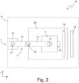
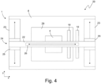
- the Figures 1 and 2 show a processing device 10 according to a first embodiment, while the Figures 3 and 4 show a processing device 20 according to a second embodiment.
- the first positioning device 1 is designed as a SCARA robot in the first embodiment and as a gantry robot in the second embodiment.
- the features that are present in both the first embodiment and the second embodiment will be discussed first.
- the processing device 10 will be discussed primarily; the explanations also apply to the processing device 20.
- the processing device 10 comprises a processing head 4, which has a processing unit 3.
- the processing unit 3 is designed as a tool and/or application unit, in particular as a printer unit.
- the processing device 10 further comprises a first positioning device 1 for moving the processing head 4 in order to position the processing unit 3 with a first accuracy at a predetermined processing position 33.
- the processing head 4 has a second positioning device 2.
- the processing device 10 is designed to position the processing unit 3 at the predetermined processing position 33 with a second accuracy using the second positioning device 2.
- the second accuracy is higher than the first accuracy, so that the lower accuracy of the first positioning device 1 is compensated by positioning with the second positioning device 2.
- the positioning error caused by positioning with the first positioning device 1 - i.e. the deviation between the position of the processing unit 3 and the specified processing position 33 - can be corrected by positioning with the second positioning device 2.
- a high level of accuracy can be achieved overall without the first positioning device 1, which positions the processing head 4 and thus generally has the larger positioning range, having to provide this high level of accuracy. Consequently, a positioning device with a large positioning range can also be used as the first positioning device 1, without thereby impairing the overall positioning accuracy of the processing device 10.
- the first positioning device 1 serves to move the machining head 4 relative to a static part of the machining device 10, for example a workpiece support 8, and/or relative to a workpiece 29.
- the first positioning device 1 has, for example, a first degree of freedom x and a second degree of freedom y for positioning the processing unit 3.
- the degrees of freedom x, y of the first positioning device 1 are linear degrees of freedom, in particular coordinates of a Cartesian coordinate system.
- a positioning plane is spanned by the two degrees of freedom x, y.
- the processing head 4 and/or the processing unit 3 can be positioned in particular in the positioning plane spanned by the degrees of freedom x, y.
- the processing device 10 has the workpiece support 8, on which the workpiece 29 is expediently arranged.
- the upper side of the workpiece support 8 and/or the upper side of the workpiece 29 is expediently aligned parallel to the positioning plane and in particular lies in the positioning plane or represents it.
- the first positioning device 1 can also be designed to move the processing head 4 in the z-direction - i.e. orthogonally to the x-direction and y-direction.
- the first positioning device 1 can thus be designed in particular to guide the processing head 4 in three-dimensional space.
- the first positioning device 1 expediently has several machine axes, in particular one or more linear machine axes and/or one or more rotational axes.
- the processing device 10 is designed in particular to position the processing unit 3 in an area using the first positioning device 1, within which a deviation from the predetermined processing position 33 can be corrected using the second positioning device 2. This area, in which a correction is possible using the second positioning device, can also be referred to as a processing window.
- the processing device 10 is expediently designed to recognize when the processing unit 3 leaves the processing window and in this case to abort or pause the processing by the processing unit 3.
- the first positioning device 1 is designed as a Scara robot.
- the first positioning device 1 accordingly comprises a robot base 31 on which a robot arm 11 is provided.
- the processing head 4 is attached or suspended at a distal end of the robot arm 11.
- the processing head 4 can be moved relative to the robot base 31 by means of the robot arm 11.
- the robot arm 11 has a first robot link 12 and a second robot link 14.
- the robot arm 11 can expediently also have further robot links.
- the processing head 4 is preferably attached to the last robot link - here the second robot link 14.
- the first robot member 12 is connected to the robot base 31 via a first machine axis 15 and can be driven relative to the robot base 31 via this first machine axis 15.
- the second robot member 14 is connected to the first robot member 12 via a second machine axis 16 and can be driven relative to the first robot member 12 via this second machine axis 16.
- the processing head 4 is connected to the second robot member 16 via a third machine axis 17 and can be driven relative to the second robot member 16 via this third machine axis 17.
- the second robot member 16 has a mechanical interface 7 to which the processing head 4 is attached, in particular in a removably manner.
- the first machine axis 15 and the second machine axis 16 expediently allow rotary movements, while the third machine axis 17 allows a rotary and a linear movement.
- a positioning device 1 designed in this way can position the processing head 4 in the x-direction, y-direction and z-direction.
- the robot base 31 is mechanically connected to the workpiece support 8; for example, the robot base 31 is arranged on the workpiece support 8 and extends upwards in the z-direction.
- the robot arm 11 extends essentially horizontally from the robot base 31 and protrudes over the x-y area of the workpiece support 8.
- the processing head 4 is suspended from the robot arm 11 and extends accordingly downwards in the z-direction to the workpiece support 8 or the workpiece 29.
- the first positioning device 1 is designed as a gantry robot, for example.
- the first positioning device 1 accordingly comprises a gantry carriage 24 that can be driven relative to the workpiece support 8 or relative to the workpiece 29.
- the gantry carriage 24 can be moved in the y-direction relative to the workpiece support 8 or relative to the workpiece 29.
- a first linear drive 23 is provided to drive the gantry carriage 24.
- the gantry carriage 24 has a gantry arm 22, on which the processing head 4 is suspended so that it can move, in particular in the x-direction.
- a second linear drive 26 is expediently provided on the gantry arm 22.
- a mechanical interface 7 is expediently provided on the gantry arm 22, to which the processing head 4 is attached, in particular in a detachable manner.
- the positioning device 1 designed as a gantry robot can position the processing head 4 in the x-direction and y-direction.
- the positioning device 1 can also be designed to position the processing head in the z-direction.
- the portal slide 24 has two vertical elements 25 which extend in the z-direction extend upwards from the workpiece support 8.
- the portal arm 22 extends from one vertical element 25 to the other vertical element 25 and together with the vertical elements 25 forms the portal carriage 24.
- the first positioning device 1 is not limited to the above-discussed embodiments as a Scara robot or gantry robot. Instead, the first positioning device 1 can also be designed as another robot device.
- the first positioning device 1 is expediently designed as an articulated arm robot, a robot with linear axes, a rail vehicle, a device traveling on a workpiece, and/or a traction system with ropes and/or chains.
- the positioning device 1 is expediently an industrial robot.
- the processing device 10 is designed, by way of example, to compensate for the lower accuracy of the first positioning device 1 in the first degree of freedom x and/or the second degree of freedom y by using the second positioning device 2.
- the second positioning device 2 expediently has the same degree of freedom x and/or the same degree of freedom y as the first positioning device 1.
- the second positioning device 2 can in particular correct a positioning error caused by the lower accuracy of the first positioning device 1 - that is, a deviation of the processing unit 3 from the predetermined processing position 33 in the x direction and/or y direction.
- the second positioning device 2 expediently has one, several or all of the degrees of freedom of the first positioning device 1.
- the second positioning device 2 preferably has an xy drive 27, for example a positioning platform, with which the processing unit 3 can be positioned relative to the processing head 4 in the x direction and in the y direction.
- the positioning device 2 also has a z drive 28, with which the processing unit 3 can be positioned relative to the processing head 4 in the z direction.
- the second positioning device 2 is preferably integrated in the processing head 4 or attached to it.
- the area, in particular the x-y area, in which the first positioning device 1 can position the processing unit 3 should also be referred to as the first positioning area.
- the area, in particular the x-y area, in which the second positioning device 2 can position the processing unit 3 should also be referred to as the second positioning area.
- the first positioning area is expediently larger than the second positioning area.
- the first positioning area is at least twice, in particular at least 10 times, expediently at least 50 times or 100 times larger than the second positioning area.
- the first positioning device 1 and the second positioning device 2 are preferably designed such that the first positioning area and the second positioning area always overlap.
- the second positioning device 2 is in particular designed such that the positioning of the processing unit 3 by the second positioning device 2 takes place with a higher accuracy and/or speed and/or rigidity than the positioning of the processing unit 3 with the first positioning device 1.
- the processing head 4 is designed as a manually operable processing device, so that the processing head 4 can be manually positioned at the predetermined processing position 33, in particular when removed from the first positioning device 1 or the processing device 10.
- the processing head 4 is designed to position the processing unit 3 at the predetermined processing position 33 with the second accuracy using the second positioning device 2, so that a lower accuracy of the manual positioning is compensated for by positioning with the second positioning device 2.
- the processing head 4 can therefore expediently be handled as an independent processing device and used to process the workpiece 29.
- the processing unit 3 designed as a tool expediently comprises a router, a saw, in particular a circular saw and/or jigsaw, a laser, a punching device, a cutting tool, in particular a textile and/or leather cutter, and/or a water jet. If the processing unit 3 is designed as an application unit, it comprises in particular a printing unit, expediently a 3D printing unit.
- the processing device 10 in particular the first positioning device 1, has a mechanical interface 7 to which the processing head 4 and/or the processing unit 3 is removably attached.
- the mechanical interface 7 can in particular be designed as a changing device with which a change of the processing head 4 and/or the processing unit 3 is possible.
- the processing head 4 - and thus in particular also the second positioning device 2 - can be firmly connected to the first positioning device 1.
- the processing device 10, in particular the first positioning device 1, can also have a lifting means, in particular a gripper and/or a vacuum suction device, for handling the processing head 4, the processing unit 3 and/or a workpiece 29.
- the lifting means can expediently represent the mechanical interface 7 mentioned above.
- one and the same lifting means can be used to fasten the processing head 4 to the first positioning device 1 during processing and to transport the workpiece 29 into or out of the processing area of the processing device 10 before and/or after processing.
- the processing device 10 is designed to position the workpiece 29 on the workpiece support 8 with the aid of the lifting means.
- the processing device 10 can expediently also comprise a change magazine for receiving at least one further processing head and/or at least one further processing unit.
- the processing device 10 has at least two different processing heads and/or two different processing units and is designed to replace the processing head 4 attached to the first positioning device 1 and/or the processing unit 3 with another processing head and/or another processing unit using the change magazine.
- the processing device 10 is designed as an example, the position of the processing unit 3 relative to the predetermined To determine the processing position 33 and to carry out the positioning of the processing unit 3 using the first positioning device and/or the second positioning device 2 based on the determined position of the processing unit 3.
- the processing device 10 is designed to recognize the processing unit 3 and/or the workpiece 29, in particular by means of a video and/or image recording, a laser scan and/or by means of ultrasound and to calculate the current position of the processing unit 3 using a position determination algorithm. On the basis of the calculated position, the further positioning or correction of the positioning can then take place with one or both of the positioning devices 1, 2, in particular with the second positioning device 2.
- the processing device 10 has, for example, a sensor unit 19, for example an image sensor, arranged in particular on the processing head 4.
- the sensor unit 19 is designed to detect a reference element 18 present on the processing device 10 and/or the workpiece 29.
- the reference element 18 is, for example, an optical marking, in particular a piece of tape, preferably a piece of adhesive tape, with a pattern printed on it.
- the reference element 18 can also be provided only on the processing device 1, for example on the workpiece support 8, and thus in particular not on the workpiece 29.
- features of the workpiece 29, for example edges, films and/or markers applied to the workpiece 29, markings applied next to and/or above the workpiece 29 on the workpiece support 8 or markings positioned in the positioning area of the first positioning device 1 or the processing device 10 (e.g. by means of stands), in particular circular markers and/or rulers, can serve as the reference element 18.
- a ruler positioned next to and/or on the workpiece 29 can expediently serve as the reference element 18.
- the sensor unit 19 can also comprise other position sensors, in particular an acceleration sensor, a laser sensor and/or an ultrasonic sensor.
- a laser and/or ultrasound source can be provided on the processing device 10, in particular on the processing head 4.
- the processing device 10 is expediently designed to determine the position of the processing unit 3 relative to the predetermined processing position 33 using the sensor unit 19.
- the processing device 10 expediently has a stored reference map in which the position of the reference element 18 is specified.
- the processing device 10 is designed to determine the position of the processing unit 3, in particular relative to the predetermined processing position 33, using the reference map and the reference element 18 detected by the sensor unit 19.
- the sensor unit 19, as mentioned above, is an image sensor and the reference element 18 is an optical marking.
- the processing device 10 is in particular designed to recognize the reference element 18 in an image recorded by the sensor unit 19 using image processing software, for example using an algorithm for machine vision, and to calculate a relative position of the sensor unit 19 or the processing unit 3 to the reference element 18 based on the recognized reference element 18. Since the position of the reference element 18 in the reference map is known, the position of the processing unit 3 in the reference map can be determined.
- a deviation of the position of the processing unit 3 from the predetermined processing position 33 can be determined, on the basis of which the positioning with the second positioning device 2 can be carried out in order to compensate for this deviation.
- the processing device 10 is designed to create the reference map as part of an initialization process.
- the processing device 10 is designed, for example, to move the processing head 4 using the first positioning device 1 in order to detect the processing area of the processing device 10 with the sensor unit 19, in particular image data of it.
- the processing device 10 is in particular designed to create the reference map based on the detected processing area, in particular on the basis of the recorded image data.
- the explained position determination of the processing unit 3 is expediently used only when positioning with the second positioning device 2 - i.e. in particular not when positioning with the first positioning device 1.
- the positioning with the first positioning device 1 can therefore be a mere control - i.e. not a regulation.
- the processing device 10 is therefore designed in particular to carry out the positioning with the first positioning device 1 as part of a control. This can mean, for example, that no feedback variable about the position of the processing head 4 or the processing unit 3 is used during positioning with the first positioning device 1.
- the positioning with the second positioning device 2 preferably takes place as a control.
- the processing device 10 is expediently designed to carry out the positioning with the second positioning device 2 as part of a control.
- the processing device 10 is designed to regulate the position of the processing unit 3 to the predetermined processing position 33.
- the processing device 10 can use a feedback variable about the position of the processing head 4 or the processing unit 3 during positioning with the second positioning device 2, for example the position of the processing unit 3 detected by the sensor unit 19.
- the processing device 10 has one or more control units, in particular computer units such as microcontrollers, in order to carry out the above-discussed determination of the position of the processing unit 3 and/or control of the processing unit 3 and/or control of the positioning devices 1, 2.
- the positioning devices 1, 2 are controlled in particular on the basis of processing data, which are provided, for example, as design/CAD data.
- the processing device 10 has a control unit, for example a microcontroller, which controls both the first positioning device 1 and the second positioning device 2.
- This control unit expediently also carries out coordination between the two positioning devices 1, 2.
- this control unit can also be designed to control or communicate with the processing unit 3 and/or the sensor unit 19.
- the processing device 10 comprises a separate control unit for each positioning device 1, 2.
- the processing device 10 has a first control unit 5 for controlling the first positioning device 1 and a second control unit 6 for controlling the second positioning device 2.
- the second control unit 6 is part of the processing head 4.
- the first control unit 5 does not control the second positioning device 2 and the second control unit 6 preferably does not control the first positioning device 1.
- Each control unit 5, 6 is preferably only responsible for one positioning device.
- the first control unit 5 and/or the second control unit 6 is designed to control the processing unit 3 in order to effect, for example, a processing of the workpiece 29.
- the first control unit 5 and/or the second control unit 6 are expediently connected to the first positioning device 1, the second positioning device 2, the processing unit 3 and/or the sensor unit 19 via wired and/or wireless data connections.
- Processing data from which in particular the aforementioned processing position 33 emerges, are expediently provided in both control units 5, 6, so that each of the control units 5, 6 can control the respectively assigned positioning device 1, 2 on the basis of the processing data.
- the control units 5, 6 can be designed differently so that they accept and/or require the processing data in different data formats.
- the processing device 10 is expediently designed to provide the first control unit 5 with processing data that define the processing position 33 in a first data format and to provide the second control unit 6 with the processing data in a second data format.
- the second data format expediently differs from the first data format.
- the first data format is a G-code data format and the second data format is a vector data format, in particular SVG.
- the first control unit 5 is designed to provide the processing data to the second control unit 6 in the second data format and/or the second control unit 6 is designed to provide the processing data to the first control unit 5 in the first data format.
- the control units 5, 6 can be designed to create and/or receive the processing data in one of the data formats, create the processing data in the other of the data formats, receive it and/or convert it into the other data format and provide the processing data in the other data format to the other control unit 5, 6.
- the processing device 10, in particular the processing head 4 can, for example, have an input device with which a user can manually enter processing data, for example in the form of one or more processing positions, into the second control unit 6.
- the processing data are then optionally converted by the second control unit 6 into the format required by the first control unit 5 and provided to the first control unit 5.
- first control unit 5 and the second control unit 6 may have processing data with different data content.
- first control unit 5 may have less precise processing data than the second control unit 6.
- first control unit 5 may be designed to control the first positioning device 1 on the basis of processing data that have a lower spatial resolution than the processing data with which the second control unit 6 controls the second positioning device 2.
- control units 5, 6 accept/require the processing data in the same data format and/or with the same data content.
- control units 5, 6 each of which controls one of the positioning devices 5, 6, it can be advantageous to carry out a position comparison between the two control units 5, 6.
- the processing device 10 is expediently designed to provide position information to the first control unit 5 and/or the second control unit 6 in order to carry out a position comparison between the first control unit 5 and the second control unit 6.
- One or both of the control units 5, 6 is expediently designed to create the position information and provide it to the other control unit 5, 6.
- the position information can in particular indicate that one of the positioning devices 1, 2 is in a specific position, for example that the processing head 4 and/or the processing unit 3 are at a zero position and/or a limit of one or both of the positioning areas.
- a time comparison for example for the purpose of temporal synchronization, can also be carried out between the two control units 5, 6.
- the processing device 10 is preferably designed to provide time information to the first control unit 5 and/or the second control unit 6 in order to carry out a time comparison between the first control unit 5 and the second control unit 6.
- One or both of the control units 5, 6 are expediently designed to create the time information and provide it to the other control unit 5, 6.
Landscapes
- Engineering & Computer Science (AREA)
- Mechanical Engineering (AREA)
- Robotics (AREA)
- Health & Medical Sciences (AREA)
- General Health & Medical Sciences (AREA)
- Orthopedic Medicine & Surgery (AREA)
- Manipulator (AREA)
- Numerical Control (AREA)
- Automatic Control Of Machine Tools (AREA)
Description
Die Erfindung betrifft eine Bearbeitungsvorrichtung mit einem Bearbeitungskopf, der eine als Werkzeug und/oder Auftrage-Einheit, insbesondere Druckereinheit, ausgebildete Bearbeitungseinheit umfasst. Die Bearbeitungsvorrichtung verfügt über eine erste Positioniereinrichtung zur Bewegung des Bearbeitungskopfs, um die Bearbeitungseinheit mit einer ersten Genauigkeit an einer vorgegebenen Bearbeitungsposition zu positionieren.The invention relates to a processing device with a processing head which comprises a processing unit designed as a tool and/or application unit, in particular a printer unit. The processing device has a first positioning device for moving the processing head in order to position the processing unit with a first accuracy at a predetermined processing position.
Als Bearbeitungsvorrichtungen kommen konventionell insbesondere CNC-Maschinen zum Einsatz, die über eine Positioniereinrichtung mit mehreren Maschinenachsen verfügen, um eine Bearbeitungseinheit, insbesondere ein Werkzeug, an einer vorgegebene Bearbeitungsposition zu positionieren. Die Genauigkeit, mit der die Bearbeitungseinheit positioniert werden kann, hängt dabei von der Genauigkeit der Positioniereinrichtung ab. Die Genauigkeit beim Positionieren wird nachstehend auch als Positioniergenauigkeit bezeichnet.CNC machines are conventionally used as processing devices, in particular, and have a positioning device with several machine axes in order to position a processing unit, in particular a tool, at a predetermined processing position. The accuracy with which the processing unit can be positioned depends on the accuracy of the positioning device. The accuracy during positioning is also referred to below as positioning accuracy.
Zudem hängt von der Positioniereinrichtung - insbesondere von der maximalen Auslenkung der Maschinenachsen der Positioniereinrichtung - die Größe des Bearbeitungsbereichs der Bearbeitungsvorrichtung ab, also derjenige Positionierbereich, in dem die Bearbeitungseinheit zur Bearbeitung positioniert werden kann.In addition, the size of the machining area of the machining device, i.e. the positioning area in which the machining unit can be positioned for machining, depends on the positioning device - in particular on the maximum deflection of the machine axes of the positioning device.
In der Regel besteht sowohl das Bedürfnis, die Bearbeitungseinheit mit einer möglichst hohen Genauigkeit positionieren zu können, als auch das Bedürfnis, einen möglichst großen Bearbeitungsbereich zur Verfügung zu haben, in dem die Bearbeitungseinheit zur Bearbeitung positioniert werden kann. Allerdings wird es mit größer werdendem Positionierbereich der Positioniereinrichtung immer schwieriger, noch eine hohe Genauigkeit zu gewährleisten.As a rule, there is both a need to be able to position the processing unit with the highest possible accuracy and a need to have as large a processing area as possible in which the processing unit can be positioned for processing. However, as the positioning range of the positioning device increases, it becomes increasingly difficult to guarantee a high level of accuracy.
Die
Eine Aufgabe der Erfindung besteht darin, eine Bearbeitungsvorrichtung bereitzustellen, bei der möglichst unabhängig von der Größe des Positionierbereichs der Positioniereinrichtung eine hohe Positioniergenauigkeit erzielt werden kann.An object of the invention is to provide a processing device in which a high positioning accuracy can be achieved as independently as possible of the size of the positioning range of the positioning device.
Die Aufgabe wird gelöst durch die im Anspruch 1 angegebenen Merkmale. Der Bearbeitungskopf der eingangs genannten Bearbeitungsvorrichtung verfügt über eine zweite Positioniereinrichtung und die Bearbeitungsvorrichtung ist ausgebildet, unter Verwendung der zweiten Positioniereinrichtung die Bearbeitungseinheit mit einer zweiten Genauigkeit an der vorgegebenen Bearbeitungsposition zu positionieren. Die zweite Genauigkeit ist dabei höher als die erste Genauigkeit, so dass durch die Positionierung mit der zweiten Positioniereinrichtung die geringere Genauigkeit der ersten Positioniereinrichtung kompensiert wird. Erfindungsgemäß ist der Bearbeitungskopf als manuell handhabbares Bearbeitungsgerät ausgebildet, so dass der Bearbeitungskopf in einem von der ersten Positioniereinrichtung abgenommenen Zustand manuell an der vorgegebenen Bearbeitungsposition positioniert werden kann und der Bearbeitungskopf ausgebildet ist, unter Verwendung der zweiten Positioniereinrichtung die Bearbeitungseinheit mit der zweiten Genauigkeit an der vorgegebenen Bearbeitungsposition zu positionieren, so dass durch die Positionierung mit der zweiten Positioniereinrichtung eine geringere Genauigkeit der manuellen Positionierung kompensiert wird.The object is achieved by the features specified in
Dadurch, dass die zweite Positioniereinrichtung die geringere Genauigkeit der ersten Positioniereinrichtung kompensiert, wird die Positioniergenauigkeit der Bearbeitungsvorrichtung nun primär durch die zweite Positioniereinrichtung gewährleistet. Die erste Positioniereinrichtung kann dementsprechend für eine geringere Genauigkeit - und damit auch ohne Schwierigkeiten für einen größeren Positionierbereich - ausgelegt werden, ohne dass dadurch die Positioniergenauigkeit der Bearbeitungsvorrichtung insgesamt beeinträchtigt wird.Because the second positioning device compensates for the lower accuracy of the first positioning device, the positioning accuracy of the processing device is now primarily ensured by the second positioning device. The first positioning device can therefore be designed for a lower accuracy - and thus also for a larger positioning range without difficulty - without this affecting the overall positioning accuracy of the processing device.
Die zweite Positioniereinrichtung benötigt selbst wiederum keinen großen Positionierbereich, da sie als Teil des mit der ersten Positioniereinrichtung positionierbaren Bearbeitungskopfs mit diesem mit bewegt bzw. positioniert wird und somit den Positionierbereich der ersten Positioniereinrichtung effektiv mit nutzt. Der Positionierbereich der zweiten Positioniereinrichtung muss letztendlich nur so groß sein, dass die maximal mögliche, aus der geringen Genauigkeit der ersten Positioniereinrichtung resultierende Abweichung zwischen der Bearbeitungseinheit und der vorgegebenen Bearbeitungsposition ausgeglichen bzw. kompensiert werden kann. Da die zweite Positioniereinrichtung nur einen relativ kleinen Positionierbereich bereitstellen muss, kann die zweite Positioniereinrichtung ohne Weiteres mit einer hohen Positioniergenauigkeit realisiert werden.The second positioning device itself does not require a large positioning area, since it is part of the processing head that can be positioned with the first positioning device and is moved or positioned with it, thus effectively using the positioning area of the first positioning device. The positioning area of the second positioning device ultimately only needs to be large enough to compensate for the maximum possible deviation between the processing unit and the specified processing position resulting from the low accuracy of the first positioning device. Since the second positioning device only has to provide a relatively small positioning range, the second positioning device can easily be implemented with a high level of positioning accuracy.
Durch die erfindungsgemäße Kombination der ersten Positioniereinrichtung und der zweiten Positioniereinrichtung wird somit der Vorteil erzielt, dass die Bearbeitungsvorrichtung insgesamt eine hohe Positioniergenauigkeit aufweisen kann, selbst dann, wenn die erste Positioniereinrichtung aufgrund eines großen bereitzustellenden Positionierbereichs eine geringere Positioniergenauigkeit aufweist.The inventive combination of the first positioning device and the second positioning device thus achieves the advantage that the processing device as a whole can have a high positioning accuracy, even if the first positioning device has a lower positioning accuracy due to a large positioning range to be provided.
Der Unterschied in der Positioniergenauigkeit zwischen der ersten Positioniereinrichtung und der zweiten Positioniereinrichtung kann sich beispielsweise daraus ergeben, dass die Positioniereinrichtungen, insbesondere die Maschinenachsen der Positioniereinrichtungen, unterschiedliche Steifigkeiten gegenüber Reaktionskräften aufweisen und/oder unterschiedliche Bewegungspräzisionen bei der Ansteuerung der Positioniereinrichtungen gegeben sind. Ferner ist es auch möglich, dass der Genauigkeitsunterschied darin begründet ist, dass die erste Positioniereinrichtung im Rahmen einer reinen Steuerung betrieben wird, während die zweite Positioniereinrichtung im Rahmen einer Regelung betrieben wird.The difference in positioning accuracy between the first positioning device and the second positioning device can result, for example, from the fact that the positioning devices, in particular the machine axes of the positioning devices, have different levels of rigidity with respect to reaction forces and/or different levels of movement precision when controlling the positioning devices. It is also possible that the difference in accuracy is due to the fact that the first positioning device is operated as part of a pure control system, while the second positioning device is operated as part of a regulation system.
Der Begriff "Genauigkeit" bzw. "Positionsgenauigkeit" soll sich insbesondere auf eine (statistische) mittlere Abweichung und/oder eine maximale Abweichung zwischen der Position der Bearbeitungseinheit und der vorgegebenen Bearbeitungsposition beziehen. Mit einer größeren Genauigkeit ist dabei eine geringere Abweichung und mit einer geringeren Genauigkeit eine größere Abweichung gemeint.The term "accuracy" or "positional accuracy" refers in particular to a (statistical) mean deviation and/or a maximum deviation between the position of the machining unit and the specified machining position. Greater accuracy means a smaller deviation and lower accuracy means a larger deviation.
Vorteilhafte Weiterbildungen sind Gegenstand der Unteransprüche.Advantageous further training is the subject of the subclaims.
Weitere Details sowie exemplarische Ausführungsformen werden nachstehend unter Bezugnahme auf die Zeichnung erläutert. Dabei zeigt
Figur 1- eine schematische Darstellung einer Bearbeitungsvorrichtung gemäß einer ersten Ausführungsform in einer Seitenansicht,
Figur 2- eine schematische Darstellung der Bearbeitungsvorrichtung gemäß der ersten Ausführungsform in einer Draufsicht,
Figur 3- eine schematische Darstellung einer Bearbeitungsvorrichtung gemäß einer zweiten Ausführungsform in einer Seitenansicht,
Figur 4- eine schematische Darstellung der Bearbeitungsvorrichtung gemäß der zweiten Ausführungsform in einer Draufsicht,
- Figure 1
- a schematic representation of a processing device according to a first embodiment in a side view,
- Figure 2
- a schematic representation of the processing device according to the first embodiment in a plan view,
- Figure 3
- a schematic representation of a processing device according to a second embodiment in a side view,
- Figure 4
- a schematic representation of the processing device according to the second embodiment in a plan view,
Die
Die Bearbeitungsvorrichtung 10 umfasst einen Bearbeitungskopf 4, der eine Bearbeitungseinheit 3 aufweist. Die Bearbeitungseinheit 3 ist als Werkzeug und/oder Auftrage-Einheit, insbesondere als Druckereinheit, ausgebildet.The
Die Bearbeitungsvorrichtung 10 umfasst ferner eine erste Positioniereinrichtung 1 zur Bewegung des Bearbeitungskopfs 4, um die Bearbeitungseinheit 3 mit einer ersten Genauigkeit an einer vorgegebenen Bearbeitungsposition 33 zu positionieren.The
Der Bearbeitungskopf 4 verfügt über eine zweite Positioniereinrichtung 2. Die Bearbeitungsvorrichtung 10 ist ausgebildet, unter Verwendung der zweiten Positioniereinrichtung 2 die Bearbeitungseinheit 3 mit einer zweiten Genauigkeit an der vorgegebenen Bearbeitungsposition 33 zu positionieren.The
Die zweite Genauigkeit ist höher als die erste Genauigkeit, so dass durch die Positionierung mit der zweiten Positioniereinrichtung 2 die geringere Genauigkeit der ersten Positioniereinrichtung 1 kompensiert wird. Durch die Positionierung mit der zweiten Positioniereinrichtung 2 kann insbesondere der durch die Positionierung mit der ersten Positioniereinrichtung 1 verursachte Positionierfehler - also die Abweichung zwischen der Position der Bearbeitungseinheit 3 und der vorgegebenen Bearbeitungsposition 33 - korrigiert werden.The second accuracy is higher than the first accuracy, so that the lower accuracy of the
Auf diese Weise kann insgesamt eine hohe Genauigkeit erzielt werden, ohne dass dafür die den Bearbeitungskopf 4 positionierende - und damit in der Regel den größeren Positionierbereich aufweisende - erste Positioniereinrichtung 1 diese hohe Genauigkeit bereitstellen muss. Folglich kann als erste Positioniereinrichtung 1 insbesondere auch eine Positioniereinrichtung mit einem großen Positionierbereich verwendet werden, ohne dadurch die Positioniergenauigkeit der Bearbeitungsvorrichtung 10 insgesamt zu beeinträchtigen.In this way, a high level of accuracy can be achieved overall without the
Im Folgenden werden exemplarische Details der Bearbeitungsvorrichtungen 10 und 20 sowie deren Komponenten erläutert. Auch hier wird der Einfachheit halber primär auf die Bearbeitungsvorrichtung 10 eingegangen, wobei die Erläuterungen in Entsprechung auch für die Bearbeitungsvorrichtung 20 gelten.In the following, exemplary details of the
Die erste Positioniereinrichtung 1 dient dazu, den Bearbeitungskopf 4 relativ zu einem statischen Teil der Bearbeitungsvorrichtung 10, beispielsweise einer Werkstück-Auflage 8, und/oder relativ zu einem Werkstück 29 zu bewegen.The
Die erste Positioniereinrichtung 1 verfügt exemplarisch über einen ersten Freiheitsgrad x und einen zweiten Freiheitgrad y zur Positionierung der Bearbeitungseinheit 3. Exemplarisch handelt es sich bei den Freiheitsgraden x, y der ersten Positioniereinrichtung 1 um lineare Freiheitsgrade, insbesondere um Koordinaten eines kartesischen Koordinatensystems. Vorzugsweise wird durch die beiden Freiheitsgrade x, y eine Positionierebene aufgespannt. Mit der ersten Positioniereinrichtung 1 lässt sich der Bearbeitungskopf 4 und/oder die Bearbeitungseinheit 3 insbesondere in der durch die Freiheitsgrade x, y aufgespannten Positionierebene positionieren.The
Exemplarisch verfügt die Bearbeitungsvorrichtung 10 über die Werkstück-Auflage 8, auf der zweckmäßigerweise das Werkstück 29 angeordnet ist. Die Oberseite der Werkstück-Auflage 8 und/oder die Oberseite des Werkstücks 29 ist zweckmäßigerweise parallel zur Positionierebene ausgerichtet und liegt insbesondere in der Positionierebene bzw. stellt diese dar.By way of example, the
Die erste Positioniereinrichtung 1 kann ferner auch ausgebildet sein, den Bearbeitungskopf 4 in z-Richtung - also orthogonal zur x-Richtung und y-Richtung zu bewegen. Die erste Positioniereinrichtung 1 kann somit insbesondere ausgebildet sein, den Bearbeitungskopf 4 im dreidimensionalen Raum zu führen.The
Die erste Positioniereinrichtung 1 verfügt zweckmäßigerweise über mehrere Maschinenachsen, insbesondere über eine oder mehrere lineare Maschinenachsen und/oder eine oder mehrere Rotationsachsen.The
Die Bearbeitungsvorrichtung 10 ist insbesondere ausgebildet, unter Verwendung der ersten Positioniereinrichtung 1 die Bearbeitungseinheit 3 in einem Bereich zu positionieren, innerhalb dem eine Abweichung zur vorgegebenen Bearbeitungsposition 33 mithilfe der zweiten Positioniereinrichtung 2 korrigiert werden kann. Dieser Bereich, in dem eine Korrektur mit der zweiten Positioniereinrichtung möglich ist, kann auch als Bearbeitungsfenster bezeichnet werden. Zweckmäßigerweise ist die Bearbeitungsvorrichtung 10 ausgebildet, zu erkennen, wenn die Bearbeitungseinheit 3 das Bearbeitungsfenster verlässt und in diesem Fall die Bearbeitung durch die Bearbeitungseinheit 3 abzubrechen oder zu pausieren.The
In den
Der Roboterarm 11 verfügt über ein erstes Roboterglied 12 und ein zweites Roboterglied 14. Zweckmäßigerweise kann der Roboterarm 11 auch über weitere Roboterglieder verfügen. Vorzugsweise ist der Bearbeitungskopf 4 an dem letzten Roboterglied - hier das zweite Roboterglied 14 - angebracht.The
Das erste Roboterglied 12 ist über eine erste Maschinenachse 15 mit der Roboterbasis 31 verbunden und über diese erste Maschinenachse 15 relativ zur Roboterbasis 31 antreibbar. Das zweite Roboterglied 14 ist über eine zweite Maschinenachse 16 mit dem ersten Roboterglied 12 verbunden und über diese zweite Maschinenachse 16 relativ zum ersten Roboterglied 12 antreibbar. Der Bearbeitungskopf 4 ist über eine dritte Maschinenachse 17 mit dem zweiten Roboterglied 16 verbunden und über diese dritte Maschinenachse 17 relativ zum zweiten Roboterglied 16 antreibbar. Exemplarisch verfügt das zweite Roboterglied 16 über eine mechanische Schnittstelle 7, an der der Bearbeitungskopf 4 insbesondere abnehmbar angebracht ist. Zweckmäßigerweise erlauben die erste Maschinenachse 15 und die zweite Maschinenachse 16 rotatorische Bewegungen, während die dritte Maschinenachse 17 eine rotatorische und eine lineare Bewegung erlaubt. Insgesamt kann eine derart ausgebildete Positioniereinrichtung 1 eine Positionierung des Bearbeitungskopfs 4 in x-Richtung, y-Richtung und z-Richtung vornehmen.The
Die Roboterbasis 31 ist mechanisch mit der Werkstück-Auflage 8 verbunden; exemplarisch ist die Roboterbasis 31 auf der Werkstück-Auflage 8 angeordnet und erstreckt sich in z-Richtung nach oben. Der Roboterarm 11 erstreckt sich im Wesentlichen horizontal von der Roboterbasis 31 und ragt über den x-y-Bereich der Werkstück-Auflage 8. Der Bearbeitungskopf 4 ist an dem Roboterarm 11 aufgehängt und erstreckt sich entsprechend in z-Richtung nach unten zu der Werkstück-Auflage 8 bzw. dem Werkstück 29.The
In den
Der Portalschlitten 24 verfügt in der gezeigten Ausgestaltung exemplarisch über zwei Vertikalelemente 25, die sich in z-Richtung von der Werkstück-Auflage 8 nach oben erstrecken. Der Portalarm 22 erstreckt sich von dem einen Vertikalelement 25 zu dem anderen Vertikalelement 25 und bildet zusammen mit den Vertikalelementen 25 den Portalschlitten 24.In the embodiment shown, the
Die erste Positioniereinrichtung 1 ist nicht auf die vorstehend diskutierten Ausgestaltungen als Scara-Roboter oder Portalroboter beschränkt. Stattdessen kann die erste Positioniereinrichtung 1 auch als eine andere Robotervorrichtung ausgestaltet sein. Zweckmäßigerweise ist die erste Positioniereinrichtung 1 als Gelenkarm-Roboter, Roboter mit linearen Achsen, Schienenfahrzeug, ein auf einem Werkstück fahrendes Gerät, und/oder ein Zug-System mit Seilen und/oder Ketten ausgebildet. Zweckmäßigerweise handelt es sich bei der Positioniereinrichtung 1 um einen Industrieroboter.The
Die Bearbeitungsvorrichtung 10 ist exemplarisch ausgebildet, unter Verwendung der zweiten Positioniereinrichtung 2 die geringere Genauigkeit der ersten Positioniereinrichtung 1 in dem ersten Freiheitsgrad x und/oder dem zweiten Freiheitsgrad y zu kompensieren.The
Zweckmäßigerweise verfügt die zweite Positioniereinrichtung 2 über den gleichen Freiheitsgrad x und/oder den gleichen Freiheitsgrad y wie die erste Positioniereinrichtung 1. Die zweite Positioniereinrichtung 2 kann insbesondere einen durch die geringere Genauigkeit der ersten Positionierungseinrichtung 1 verursachten Positionierungsfehler - also eine Abweichung der Bearbeitungseinheit 3 von der vorgegebenen Bearbeitungsposition 33 in x-Richtung und/oder y-Richtung korrigieren. Zweckmäßigerweise verfügt die zweite Positioniereinrichtung 2 über einen, mehrere oder sämtliche Freiheitsgrade der ersten Positioniereinrichtung 1.The
Wie in den
Der Bereich, insbesondere der x-y-Bereich, in dem die erste Positioniereinrichtung 1 die Bearbeitungseinheit 3 positionieren kann, soll auch als erster Positionierbereich bezeichnet werden. Der Bereich, insbesondere der x-y-Bereich, in dem die zweite Positioniereinrichtung 2 die Bearbeitungseinheit 3 positionieren kann, soll auch als zweiter Positionierbereich bezeichnet werden. Zweckmäßigerweise ist der erste Positionierbereich größer als der zweite Positionierbereich. Beispielsweise ist der erste Positionierbereich flächenmäßig wenigstens 2-mal, insbesondere wenigstens 10-mal, zweckmäßigerweise wenigstens 50-mal oder 100-mal so groß wie der zweite Positionierbereich. Vorzugsweise sind die erste Positioniereinrichtung 1 und die zweite Positioniereinrichtung 2 derart ausgebildet, dass sich der erste Positionierbereich und der zweite Positionierbereich stets überlappen.The area, in particular the x-y area, in which the
Die zweite Positioniereinrichtung 2 ist insbesondere derart ausgebildet, dass die Positionierung der Bearbeitungseinheit 3 durch die zweite Positioniereinrichtung 2 mit einer höheren Genauigkeit und/oder Geschwindigkeit und/oder Steifigkeit als die Positionierung der Bearbeitungseinheit 3 mit der ersten Positioniereinrichtung 1 erfolgt.The
Der Bearbeitungskopf 4 ist als manuell handhabbares Bearbeitungsgerät ausgebildet, so dass der Bearbeitungskopf 4 insbesondere in einem von der ersten Positioniereinrichtung 1 bzw. der Bearbeitungsvorrichtung 10 abgenommenen Zustand manuell an der vorgegebenen Bearbeitungsposition 33 positioniert werden kann. Der Bearbeitungskopf 4 ist ausgebildet, unter Verwendung der zweiten Positioniereinrichtung 2 die Bearbeitungseinheit 3 mit der zweiten Genauigkeit an der vorgegebenen Bearbeitungsposition 33 zu positionieren, so dass durch die Positionierung mit der zweiten Positioniereinrichtung 2 eine geringere Genauigkeit der manuellen Positionierung kompensiert wird. Zweckmäßigerweise kann der Bearbeitungskopf 4 also als eigenständiges Bearbeitungsgerät gehandhabt und zur Bearbeitung des Werkstücks 29 verwendet werden.The
Die als Werkzeug ausgebildete Bearbeitungseinheit 3 umfasst zweckmäßigerweise eine Oberfräse, eine Säge, insbesondere eine Kreissäge und/oder Stichsäge, einen Laser, eine Stanzeinrichtung, ein Schneidwerkzeug, insbesondere einen Textil- und/oder Leder-Cutter, und/oder einen Wasserstrahler. Sofern die Bearbeitungseinheit 3 als Auftrage-Einheit ausgebildet ist, umfasst sie insbesondere eine Druckeinheit, zweckmäßigerweise eine 3D-Druckeinheit.The
Exemplarisch verfügt die Bearbeitungsvorrichtung 10, insbesondere die erste Positioniereinrichtung 1 über eine mechanische Schnittstelle 7, an der der Bearbeitungskopf 4 und/oder die Bearbeitungseinheit 3 abnehmbar angebracht ist. Die mechanische Schnittstelle 7 kann insbesondere als Wechseleinrichtung ausgebildet sein, mit der ein Wechsel des Bearbeitungskopfs 4 und/oder der Bearbeitungseinheit 3 möglich ist.By way of example, the
Alternativ kann der Bearbeitungskopf 4 - und somit insbesondere auch die zweite Positioniereinrichtung 2 - fest mit der ersten Positioniereinrichtung 1 verbunden sein.Alternatively, the processing head 4 - and thus in particular also the second positioning device 2 - can be firmly connected to the
Die Bearbeitungsvorrichtung 10, insbesondere die erste Positioniereinrichtung 1 kann ferner auch über ein Hebemittel, insbesondere einen Greifer und/oder eine Vakuum-Ansaugeinrichtung, zum Handhaben des Bearbeitungskopfs 4, der Bearbeitungseinheit 3 und/oder eines Werkstücks 29 verfügen. Das Hebemittel kann zweckmäßigerweise die vorstehend erwähnte mechanische Schnittstelle 7 darstellen. Zweckmäßigerweise kann ein und dasselbe Hebemittel verwendet werden, um zum einen während der Bearbeitung den Bearbeitungskopf 4 an der ersten Positioniereinrichtung 1 zu befestigen und zum anderen vor und/oder nach der Bearbeitung das Werkstück 29 in oder aus dem Bearbeitungsbereich der Bearbeitungsvorrichtung 10 zu befördern. Zweckmäßigerweise ist die Bearbeitungsvorrichtung 10 ausgebildet, mithilfe des Hebemittels das Werkstück 29 auf der Werkstück-Auflage 8 zu positionieren.The
Zweckmäßigerweise kann die Bearbeitungsvorrichtung 10 auch ein Wechselmagazin zur Aufnahme wenigstens eines weiteren Bearbeitungskopfs und/oder wenigstens einer weiteren Bearbeitungseinheit umfassen. Beispielsweise verfügt die Bearbeitungsvorrichtung 10 über wenigstens zwei verschiedene Bearbeitungsköpfe und/oder zwei verschiedene Bearbeitungseinheiten und ist ausgebildet, den an der ersten Positioniereinrichtung 1 angebrachten Bearbeitungskopf 4 und/oder die Bearbeitungseinheit 3 unter Verwendung des Wechselmagazins durch einen anderen Bearbeitungskopf und/oder eine andere Bearbeitungseinheit zu ersetzen.The
Die Bearbeitungsvorrichtung 10 ist exemplarisch ausgebildet, die Position der Bearbeitungseinheit 3 relativ zu der vorgegebenen Bearbeitungsposition 33 zu bestimmen und die Positionierung der Bearbeitungseinheit 3 unter Verwendung der ersten Positioniereinrichtung und/oder der zweiten Positioniereinrichtung 2 basierend auf der bestimmten Position der Bearbeitungseinheit 3 durchzuführen. Beispielsweise ist die Bearbeitungsvorrichtung 10 ausgebildet, die Bearbeitungseinheit 3 und/oder das Werkstück 29 insbesondere mittels einer Video- und/oder Bildaufnahme, einem Laserscan und/oder mittels Ultraschall zu erkennen und anhand von einem Positionsbestimmungsalgorithmus die aktuelle Position der Bearbeitungseinheit 3 zu berechnen. Auf Basis der berechneten Position kann dann die weitere Positionierung bzw. Korrektur der Positionierung mit einer oder beiden der Positioniereinrichtungen 1, 2, insbesondere mit der zweiten Positioniereinrichtung 2 erfolgen.The
Insbesondere ist die Bearbeitungsvorrichtung 10 ausgebildet, die Bearbeitungseinheit 3 und/oder das Werkstück 29 mittels einer Video- und/oder Bilderkennung/-verarbeitung und/oder durch Scannen des Werkstücks und/oder durch Auswertung von Ultraschall zu erkennen. Ferner kann die Bearbeitungsvorrichtung 10 ausgebildet sein, unter Verwendung anderer Lagesensoren und/oder Algorithmen auf Basis von Sensordaten (beispielsweise Video, Bilder, Laser, Ultraschall) die Position des Werkstücks 29 und/oder der Bearbeitungseinheit 3 zu ermitteln. Hierfür benötigte Sensoren können an den Positioniereinrichtungen 1, 2, dem Bearbeitungskopf 4 und/oder stationär angeordnet und/oder angebracht sein.In particular, the
Die Bearbeitungsvorrichtung 10 verfügt exemplarisch über eine insbesondere am Bearbeitungskopf 4 angeordnete Sensoreinheit 19, beispielsweise über einen Bildsensor. Die Sensoreinheit 19 ist ausgebildet, ein an der Bearbeitungsvorrichtung 10 und/oder dem Werkstück 29 vorhandenes Referenzelement 18 zu erfassen. Das Referenzelement 18 ist beispielsweise eine optische Markierung, insbesondere ein Stück Band, vorzugsweise ein Stück Klebeband, mit einem aufgedruckten Muster.The
Gemäß einer nicht gezeigten Ausgestaltung kann das Referenzelement 18 auch nur an der Bearbeitungsvorrichtung 1 vorgesehen sein, beispielsweise an der Werkstück-Auflage 8, und somit insbesondere nicht an dem Werkstück 29.According to an embodiment not shown, the
Als das Referenzelement 18 können ferner Merkmale des Werkstücks 29, beispielsweise Kanten, auf dem Werkstück 29 aufgebrachte Folien und/oder Marker, neben und/oder über dem Werkstück 29 an der Werkstück-Auflage 8 angebrachte Markierungen oder im Positionierbereich der ersten Positioniereinrichtung 1 oder der Bearbeitungsvorrichtung 10 positionierte Markierungen (z.B. mittels Stativen), insbesondere Kreismarker und/oder Lineale dienen. Zweckmäßigerweise kann ein neben und/oder auf dem Werkstück 29 positioniertes Lineal als das Referenzelement 18 dienen.Furthermore, features of the
Alternativ oder zusätzlich zu der genannten Ausführung als Bildsensor kann die Sensoreinheit 19 auch andere Lagesensoren umfassen, insbesondere einen Beschleunigungssensor, einen Lasersensor und/oder einen Ultraschallsensor. Zur Positionsbestimmung mittels Laser und/oder Ultraschall kann an der Bearbeitungsvorrichtung 10, insbesondere an dem Bearbeitungskopf 4 eine Laser- und/oder Ultraschallquelle vorgesehen sein.Alternatively or in addition to the aforementioned embodiment as an image sensor, the
Die Bearbeitungsvorrichtung 10 ist zweckmäßigerweise ausgebildet, unter Verwendung der Sensoreinheit 19 die Position der Bearbeitungseinheit 3 relativ zu der vorgegebenen Bearbeitungsposition 33 zu bestimmen.The
Zweckmäßigerweise verfügt die Bearbeitungsvorrichtung 10 über eine abgespeicherte Referenzkarte, in der die Position des Referenzelements 18 angegeben ist. Die Bearbeitungsvorrichtung 10 ist ausgebildet, unter Verwendung der Referenzkarte und des mit der Sensoreinheit 19 erfassten Referenzelements 18 die Position der Bearbeitungseinheit 3 zu bestimmen, insbesondere relativ zu der vorgegebenen Bearbeitungsposition 33. Beispielsweise handelt es sich bei der Sensoreinheit 19, wie vorstehend erwähnt, um einen Bildsensor, und bei dem Referenzelement 18 um eine optische Markierung. Die Bearbeitungsvorrichtung 10 ist insbesondere ausgebildet, unter Verwendung einer Bildverarbeitungssoftware, beispielsweise unter Verwendung eines Algorithmus für maschinelles Sehen, das Referenzelement 18 in einem von der Sensoreinheit 19 aufgenommenen Bild zu erkennen und basierend auf dem erkannten Referenzelement 18 eine relative Position der Sensoreinheit 19 bzw. der Bearbeitungseinheit 3 zu dem Referenzelement 18 zu berechnen. Da die Position des Referenzelements 18 in der Referenzkarte bekannt ist, kann so die Position der Bearbeitungseinheit 3 in der Referenzkarte ermittelt werden.The
Auf diese Weise kann eine Abweichung der Position der Bearbeitungseinheit 3 von der vorgegebenen Bearbeitungsposition 33 ermittelt werden, anhand welcher wiederum die Positionierung mit der zweiten Positioniereinrichtung 2 erfolgen kann, um diese Abweichung zu kompensieren.In this way, a deviation of the position of the
Vorzugsweise ist die Bearbeitungsvorrichtung 10 ausgebildet, im Rahmen eines Initialisierungsprozesses die Referenzkarte zu erstellen. Zu diesem Zweck ist die Bearbeitungsvorrichtung 10 beispielsweise ausgebildet, unter Verwendung der ersten Positioniereinrichtung 1 den Bearbeitungskopf 4 zu verfahren, um so mit der Sensoreinheit 19 den Bearbeitungsbereich der Bearbeitungsvorrichtung 10 zu erfassen, insbesondere Bilddaten davon aufzunehmen. Die Bearbeitungsvorrichtung 10 ist insbesondere ausgebildet, basierend auf dem erfassten Bearbeitungsbereich, insbesondere auf Basis der aufgenommenen Bilddaten, die Referenzkarte zu erstellen.Preferably, the
Zweckmäßigerweise wird die erläuterte Positionsbestimmung der Bearbeitungseinheit 3 nur bei der Positionierung mit der zweiten Positioniereinrichtung 2 - also insbesondere nicht bei der Positionierung mit der ersten Positioniereinrichtung 1 - verwendet.The explained position determination of the
Bei der Positionierung mit der ersten Positioniereinrichtung 1 kann es sich dementsprechend insbesondere um eine bloße Steuerung - also keine Regelung - handeln. Die Bearbeitungsvorrichtung 10 ist folglich insbesondere ausgebildet, die Positionierung mit der ersten Positioniereinrichtung 1 im Rahmen einer Steuerung durchzuführen. Dies kann beispielsweise bedeuten, dass bei der Positionierung mit der ersten Positioniereinrichtung 1 keine Rückkopplungsgröße über die Position des Bearbeitungskopfs 4 oder der Bearbeitungseinheit 3 verwendet wird.The positioning with the
Die Positionierung mit der zweiten Positioniereinrichtung 2 findet hingegen vorzugsweise als Regelung statt. Zweckmäßigerweise ist die Bearbeitungsvorrichtung 10 ausgebildet, die Positionierung mit der zweiten Positioniereinrichtung 2 im Rahmen einer Regelung durchzuführen. Insbesondere ist die Bearbeitungsvorrichtung 10 ausgebildet, die Position der Bearbeitungseinheit 3 auf die vorgegebene Bearbeitungsposition 33 zu regeln. Zu diesem Zweck kann die Bearbeitungsvorrichtung 10 bei der Positionierung mit der zweiten Positioniereinrichtung 2 eine Rückkopplungsgröße über die Position des Bearbeitungskopfs 4 oder der Bearbeitungseinheit 3 verwenden, beispielsweise die mit Hilfe der Sensoreinheit 19 erfasste Position der Bearbeitungseinheit 3.The positioning with the
Die Bearbeitungsvorrichtung 10 verfügt über eine oder mehrere Steuereinheiten, insbesondere Rechnereinheiten wie z.B. Mikrocontroller, um die vorstehend diskutierte Bestimmung der Position der Bearbeitungseinheit 3 und/oder eine Ansteuerung der Bearbeitungseinheit 3 und/oder eine Ansteuerung der Positioniereinrichtungen 1, 2 durchzuführen. Die Ansteuerung der Positioniereinrichtungen 1, 2 erfolgt insbesondere auf Basis von Bearbeitungsdaten, die beispielsweise als Design-/CAD-Daten bereitgestellt werden.The
In einer nicht gezeigten Ausgestaltung verfügt die Bearbeitungsvorrichtung 10 über eine Steuereinheit, beispielsweise einen Mikrocontroller, die sowohl die erste Positioniereinrichtung 1 wie auch die zweite Positioniereinrichtung 2 ansteuert. Zweckmäßigerweise führt diese Steuereinheit auch eine Abstimmung zwischen den beiden Positioniereinrichtungen 1, 2 durch. Ferner kann diese Steuereinheit auch zur Ansteuerung bzw. Kommunikation mit der Bearbeitungseinheit 3 und/oder der Sensoreinheit 19 ausgebildet sein.In an embodiment not shown, the
In den gezeigten Ausführungsbeispielen hingegen umfasst die Bearbeitungsvorrichtung 10 für jede Positioniereinrichtung 1, 2 eine eigene Steuereinheit. So verfügt die Bearbeitungsvorrichtung 10 exemplarisch über eine erste Steuereinheit 5 zur Ansteuerung der ersten Positioniereinrichtung 1 und eine zweite Steuereinheit 6 zur Ansteuerung der zweiten Positioniereinrichtung 2. Exemplarisch ist die zweite Steuereinheit 6 Teil des Bearbeitungskopfs 4.In the exemplary embodiments shown, however, the
Vorzugsweise steuert die erste Steuereinheit 5 nicht die zweite Positioniereinrichtung 2 an und die zweite Steuereinheit 6 steuert vorzugsweise nicht die erste Positioniereinrichtung 1 an. Jede Steuereinheit 5, 6 ist vorzugsweise nur für eine Positioniereinrichtung zuständig.Preferably, the
Vorzugsweise ist die erste Steuereinheit 5 und/oder die zweite Steuereinheit 6 ausgebildet, die Bearbeitungseinheit 3 anzusteuern um beispielsweise eine Bearbeitung des Werkstücks 29 zu bewirken.Preferably, the
Zweckmäßigerweise ist die erste Steuereinheit 5 und/oder die zweite Steuereinheit 6 über drahtgebundene und/oder drahtlose Datenverbindungen mit der ersten Positioniereinrichtung 1, der zweiten Positioniereinrichtung 2, der Bearbeitungseinheit 3 und/oder der Sensoreinheit 19 verbunden.The
Bearbeitungsdaten, aus denen insbesondere die erwähnte Bearbeitungsposition 33 hervorgeht, werden zweckmäßigerweise in beiden Steuereinheiten 5, 6 bereitgestellt, so dass jede der Steuereinheiten 5, 6 die Ansteuerung der jeweils zugeordneten Positioniereinrichtung 1, 2 auf Basis der Bearbeitungsdaten durchführen kann.Processing data, from which in particular the
Die Steuereinheiten 5, 6 können unterschiedlich ausgebildet sein, so dass sie die Bearbeitungsdaten in unterschiedlichen Datenformaten akzeptieren und/oder benötigen. Zweckmäßigerweise ist die Bearbeitungsvorrichtung 10 ausgebildet, der ersten Steuereinheit 5 Bearbeitungsdaten, die die Bearbeitungsposition 33 definieren, in einem ersten Datenformat bereitzustellen und der zweiten Steuereinheit 6 die Bearbeitungsdaten in einem zweiten Datenformat bereitzustellen. Das zweite Datenformat unterscheidet sich zweckmäßigerweise von dem ersten Datenformat. Beispielsweise ist das erste Datenformat ein G-Code-Datenformat und das zweite Datenformat ein Vektor-Datenformat, insbesondere SVG.The
Exemplarisch ist die erste Steuereinheit 5 ausgebildet, der zweiten Steuereinheit 6 die Bearbeitungsdaten in dem zweiten Datenformat bereitzustellen und/oder die zweite Steuereinheit 6 ist ausgebildet, die Bearbeitungsdaten der ersten Steuereinheit 5 in dem ersten Datenformat bereitzustellen. Beispielsweise kann eine oder beide der Steuereinheiten 5, 6 ausgebildet sein, die Bearbeitungsdaten in einem der Datenformate zu erstellen und/oder zu empfangen, die Bearbeitungsdaten in dem anderen der Datenformate zu erstellen, empfangen und/oder in das andere Datenformat zu konvertieren und die Bearbeitungsdaten in dem anderen Datenformat der anderen Steuereinheit 5, 6 bereitzustellen.By way of example, the
Die Bearbeitungsvorrichtung 10, insbesondere der Bearbeitungskopf 4, kann beispielsweise über eine Eingabevorrichtung verfügen, mit der ein Benutzer manuell Bearbeitungsdaten, beispielsweise in der Form einer oder mehrerer Bearbeitungspositionen, in die zweite Steuereinheit 6 eingeben kann. Die Bearbeitungsdaten werden dann optional von der zweiten Steuereinheit 6 in das von der ersten Steuereinheit 5 benötigte Format konvertiert und der ersten Steuereinheit 5 bereitgestellt.The
Ferner ist es möglich, dass die erste Steuereinheit 5 und die zweite Steuereinheit 6 über Bearbeitungsdaten mit unterschiedlichem Dateninhalt verfügen. Beispielsweise kann die erste Steuereinheit 5 über ungenauere Bearbeitungsdaten als die zweite Steuereinheit 6 verfügen. Insbesondere kann die erste Steuereinheit 5 ausgebildet sein, die Ansteuerung der ersten Positioniereinrichtung 1 auf Basis von Bearbeitungsdaten durchzuführen, die eine geringere räumliche Auflösung haben als die Bearbeitungsdaten, mit der die zweite Steuereinheit 6 die zweite Positioniereinrichtung 2 ansteuert.It is also possible for the
Es ist ferner auch möglich, dass die Steuereinheiten 5, 6 die Bearbeitungsdaten in dem gleichen Datenformat und/oder mit dem gleichen Dateninhalt akzeptieren/benötigen.It is also possible that the
Sofern zwei Steuereinheiten 5, 6 vorhanden sind, die jeweils eine der Positioniereinrichtungen 5, 6 ansteuern, kann es von Vorteil sein, einen Positionsabgleich zwischen den beiden Steuereinheiten 5, 6 durchzuführen.If two
Zweckmäßigerweise ist die Bearbeitungsvorrichtung 10 ausgebildet, der ersten Steuereinheit 5 und/oder der zweiten Steuereinheit 6 eine Positionsinformation bereitzustellen, um einen Positionsabgleich zwischen der ersten Steuereinheit 5 und der zweiten Steuereinheit 6 durchzuführen. Zweckmäßigerweise ist eine oder beider der Steuereinheiten 5, 6 ausgebildet, die Positionsinformation zu erstellen und der anderen Steuereinheit 5, 6 bereitzustellen. Die Positionsinformation kann insbesondere anzeigen, dass eine der Positioniereinrichtungen 1, 2 sich in einer bestimmten Stellung befindet, beispielsweise, dass sich der Bearbeitungskopf 4 und/oder die Bearbeitungseinheit 3 an einer Nullposition und/oder einer Grenze eines oder beider der Positionierbereiche befinden.The
Alternativ und/oder zusätzlich zu dem Positionsabgleich kann auch ein Zeitabgleich, beispielsweise zum Zwecke der zeitlichen Synchronisation, zwischen den beiden Steuereinheiten 5, 6 erfolgen. Vorzugsweise ist die Bearbeitungsvorrichtung 10 ausgebildet, der ersten Steuereinheit 5 und/oder der zweiten Steuereinheit 6 eine Zeitinformation bereitzustellen, um einen Zeitabgleich zwischen der ersten Steuereinheit 5 und der zweiten Steuereinheit 6 durchzuführen. Zweckmäßigerweise ist eine oder beider der Steuereinheiten 5, 6 ausgebildet, die Zeitinformation zu erstellen und der anderen Steuereinheit 5, 6 bereitzustellen.Alternatively and/or in addition to the position comparison, a time comparison, for example for the purpose of temporal synchronization, can also be carried out between the two
Claims (14)
- Processing device (10; 20) with a processing head (4), the processing head (4) comprising a processing unit (3) designed as a tool and/or applicator unit, in particular a printer unit, and a first positioning device (1) for moving the processing head (4) in order to position the processing unit (3) with a first accuracy at a specified processing position (33), wherein the processing head (4) has a second positioning device (2) and the processing device (10; 20) is configured to position the processing unit (3) at the specified processing position (33) with a second accuracy using the second positioning device (2), the second accuracy being higher than the first accuracy, so that the lower accuracy of the first positioning device (2) is compensated for by the positioning with the second positioning device (2), characterized in that the processing head (4) is designed as a hand-guided processing device, so that the processing head (4) can be positioned manually at the specified processing position (33), in a state in which the processing head (4) is removed from the first positioning device (1), and the processing head (4) is configured to position the processing unit (3) with the second accuracy at the specified processing position (33) using the second positioning device (2), so that a lower accuracy of the manual positioning is compensated by the positioning with the second positioning device (2).
- Processing device (10; 20) according to claim 1, characterised in that the processing device (10; 20) has a first control unit (5) for controlling the first positioning device (1) and a second control unit (6) for controlling the second positioning device (2).
- Processing device (10; 20) according to claim 2, characterized in that the processing device (10; 20) is configured to provide the first control unit (5) with processing data defining the processing position (33) in a first data format and to provide the second control unit (6) with the processing data in a second data format.
- Processing device (10; 20) according to claim 2 or 3, characterized in that the processing device (10; 20) is configured to provide position information to the first control unit (5) and/or the second control unit (6) in order to perform a position calibration between the first control unit (5) and the second control unit (6).
- Processing device (10; 20) according to one of claims 2 to 4, characterized in that the processing device (10; 20) is configured to provide the first control unit (5) and/or the second control unit (6) with time information in order to carry out a time alignment between the first control unit (5) and the second control unit (6).
- Processing device (10; 20) according to one of the above claims, characterized in that the processing device (10) is configured to carry out the positioning with the first positioning device (1) within an open-loop control and to carry out the positioning with the second positioning device within a closed-loop control.
- Processing device (10; 20) according to a preceding claim, characterized in that the first positioning device (1) has a first degree of freedom (x) and/or a second degree of freedom (y) for positioning the processing unit (3), and the processing device (10; 20) is adapted to compensate, using the second positioning device (2), for the lower accuracy of the first positioning device (1) in the first degree of freedom (x) and/or the second degree of freedom (y).
- Processing device (10; 20) according to a preceding claim, characterized in that the processing device (10) is adapted to determine the position of the processing unit (3) relative to the specified processing position (33) and to perform the positioning of the processing unit (3) using the first positioning device and/or the second positioning device (2) based on the determined position of the processing unit (3).
- Processing device (10; 20) according to claim 8, characterized in that the processing device (10) has a sensor unit (19), in particular an image sensor, arranged in particular on the processing head (4), for detecting a reference element (18), in particular an optical marking, present on the processing device (10; 20) and/or a workpiece (29), and is configured to determine the position of the processing unit (3) relative to the specified processing position (33) using the sensor unit (19).
- Processing device (10; 20) according to one of the above claims, characterized in that the first positioning device (1) comprises a robot device, an industrial robot, a gantry robot, a SCARA robot, an articulated arm robot, a robot with linear axes, a rail vehicle, an apparatus travelling on a workpiece, and/or a traction system with ropes and/or chains.
- Processing device (10; 20) according to one of the above claims, characterized in that the tool comprises a router, a saw, in particular a circular saw and/or jigsaw, a laser, a punching device, a cutting tool, in particular a textile and/or leather cutter, and/or a water jet and/or the applicator unit comprises a printing unit, expediently a 3D printing unit.
- Processing device (10; 20) according to one of the above claims, characterised in that the processing device (10; 20), in particular the first positioning device (1), has a mechanical interface (7) to which the processing head (4) and/or the processing unit (3) is detachably attached.
- Processing device (10; 20) according to one of the above claims, characterised in that the processing device (10; 20), in particular the first positioning device (1), has a lifting means, in particular a gripper and/or a vacuum suction device, for handling the processing head (4), the processing unit (3) and/or a workpiece (29).
- Processing device (10; 20) according to one of the above claims, characterised in that the processing device (10; 20) has a changing magazine for receiving at least one further processing head and/or at least one further processing unit.
Applications Claiming Priority (2)
| Application Number | Priority Date | Filing Date | Title |
|---|---|---|---|
| DE102018200551.6A DE102018200551A1 (en) | 2018-01-15 | 2018-01-15 | processing device |
| PCT/EP2018/083520 WO2019137695A1 (en) | 2018-01-15 | 2018-12-04 | Machining device |
Publications (2)
| Publication Number | Publication Date |
|---|---|
| EP3710198A1 EP3710198A1 (en) | 2020-09-23 |
| EP3710198B1 true EP3710198B1 (en) | 2024-10-02 |
Family
ID=64664257
Family Applications (1)
| Application Number | Title | Priority Date | Filing Date |
|---|---|---|---|
| EP18815989.1A Active EP3710198B1 (en) | 2018-01-15 | 2018-12-04 | Machining device |
Country Status (5)
| Country | Link |
|---|---|
| US (1) | US11667032B2 (en) |
| EP (1) | EP3710198B1 (en) |
| CN (1) | CN111565886B (en) |
| DE (1) | DE102018200551A1 (en) |
| WO (1) | WO2019137695A1 (en) |
Families Citing this family (4)
| Publication number | Priority date | Publication date | Assignee | Title |
|---|---|---|---|---|
| CN116442210B (en) * | 2022-01-10 | 2024-12-06 | 腾讯科技(深圳)有限公司 | Redundant robot motion control method and redundant robot |
| DE102022101741A1 (en) | 2022-01-26 | 2023-07-27 | Schaeffler Technologies AG & Co. KG | punching device |
| KR102780717B1 (en) * | 2022-11-30 | 2025-03-12 | 주식회사 씨엔 | Scara robot |
| DE102023118134B3 (en) | 2023-07-10 | 2025-01-09 | Dr. Ing. H.C. F. Porsche Aktiengesellschaft | Cutting processing arrangement for processing a sheet metal part and method |
Family Cites Families (15)
| Publication number | Priority date | Publication date | Assignee | Title |
|---|---|---|---|---|
| JPS5485678A (en) | 1977-12-20 | 1979-07-07 | Canon Inc | High accuracy alignment method for air bearing guide system xy stage |
| US4812666A (en) * | 1987-09-17 | 1989-03-14 | Universal Instruments Corporation | Position feedback enhancement over a limited repositioning area for a moveable member |
| JPH07128467A (en) | 1993-11-02 | 1995-05-19 | Canon Inc | Micromotion carrier |
| DE10230021C1 (en) * | 2002-07-04 | 2003-07-10 | Daimler Chrysler Ag | Method of cleaning motor vehicle body panel involves using contact cleaning head with manipulator having rough and fine positioning controls |
| JP4577107B2 (en) * | 2005-06-17 | 2010-11-10 | 三菱電機株式会社 | Machine position controller |
| KR100676825B1 (en) * | 2005-10-14 | 2007-02-01 | 삼성전자주식회사 | Work machinery and work tools for machinery |
| DE102006049627A1 (en) * | 2006-10-20 | 2008-04-24 | Fraunhofer-Gesellschaft zur Förderung der angewandten Forschung e.V. | Method and device for fine positioning of a tool with a handling device |
| DE102007028934A1 (en) * | 2007-06-22 | 2008-12-24 | Trumpf Werkzeugmaschinen Gmbh + Co. Kg | Method for optimized motion coordination of measuring or machine tools with redundant translationally effective axes |
| JP5031459B2 (en) * | 2007-06-27 | 2012-09-19 | 株式会社アルバック | Coarse / fine movement apparatus and liquid supply apparatus including the same |
| CN201573076U (en) * | 2009-11-19 | 2010-09-08 | 昆山昆得精密电子科技有限公司 | Tool fine tuning device |
| DE102011006679B4 (en) * | 2011-03-16 | 2018-07-12 | Ferrobotics Compliant Robot Technology Gmbh | Active handling device and method for contact tasks |
| CN202684742U (en) * | 2012-06-28 | 2013-01-23 | 无锡市海鸿精工机械制造有限公司 | Feeding mechanism of grinder |
| WO2015087411A1 (en) | 2013-12-11 | 2015-06-18 | 住友化学株式会社 | Processing apparatus and processing method |
| AT519718B1 (en) * | 2017-02-28 | 2018-12-15 | Fill Gmbh | Articulated robot and method for machining a workpiece by means of the articulated robot |
| US10513856B2 (en) * | 2017-03-31 | 2019-12-24 | Canvas Construction, Inc. | Automated drywall planning system and method |
-
2018
- 2018-01-15 DE DE102018200551.6A patent/DE102018200551A1/en not_active Withdrawn
- 2018-12-04 EP EP18815989.1A patent/EP3710198B1/en active Active
- 2018-12-04 WO PCT/EP2018/083520 patent/WO2019137695A1/en not_active Ceased
- 2018-12-04 US US16/961,950 patent/US11667032B2/en active Active
- 2018-12-04 CN CN201880086611.9A patent/CN111565886B/en active Active
Also Published As
| Publication number | Publication date |
|---|---|
| CN111565886B (en) | 2022-07-19 |
| WO2019137695A1 (en) | 2019-07-18 |
| US20200384641A1 (en) | 2020-12-10 |
| US11667032B2 (en) | 2023-06-06 |
| DE102018200551A1 (en) | 2019-07-18 |
| CN111565886A (en) | 2020-08-21 |
| EP3710198A1 (en) | 2020-09-23 |
Similar Documents
| Publication | Publication Date | Title |
|---|---|---|
| DE102018112820B4 (en) | Teach position correction device and teach position correction method | |
| EP3710198B1 (en) | Machining device | |
| EP1966661B1 (en) | Method and apparatus for establishing a trajectory of a robot device | |
| DE102009014766B4 (en) | Superimposed axes in a device for machining a workpiece with a tool | |
| DE102016115987A1 (en) | COORDINATE SYSTEM SETTING METHOD, COORDINATE SYSTEM ADJUSTMENT DEVICE AND ROBOT SYSTEM WITH COORDINATE SYSTEM ADJUSTMENT DEVICE | |
| EP2012208B1 (en) | Programmable hand tool | |
| EP3147086A1 (en) | Automation of robot operations | |
| DE602006000541T2 (en) | Servo control apparatus and method for adjusting a servo system | |
| DE112021000584T5 (en) | Robot controller, robot system, control method and program | |
| DE102007019453B4 (en) | Coordinate measuring machine with two carriages on a common guide | |
| DE102020119550B4 (en) | Device, robot control device, robot system and method for setting a robot coordinate system | |
| EP1172183A2 (en) | Device and arrangement for generating corrected motion data for predefined motion of a mobile installation, mobile installation and system comprising mobile installations | |
| WO2017063636A1 (en) | Device and method for laser-beam machining a workpiece designed as a switch cabinet component | |
| DE102021128336A1 (en) | System and method for calibrating and/or controlling movable multi-bar kinematics | |
| DE102007058293A1 (en) | Calibrating device for adjusting robot coordinate system of industrial robot, has base carrier and multiple markers which are indirectly fastened to base carrier and lie in level | |
| DE10302592A1 (en) | Control of the operation and positioning of a processing unit, e.g. an industrial robot, whereby once a work position is reached, its position is first checked and adjusted before a process is initiated | |
| EP3541586A1 (en) | Method and robot control system for creating a path of a robot | |
| EP3083159B1 (en) | Positioning device | |
| EP3996855B1 (en) | Method for positioning an operating apparatus in respect of a bending machine | |
| DE102013210739B3 (en) | Coordinate measuring machine for measuring workpiece, has drive unit that exerts directed force on thrust unit, such that amount, direction and point of application can be chosen and torque acting on measuring unit is specific value | |
| DE102009034938B4 (en) | Method for commanding a movement system with a measuring device | |
| WO2017181208A1 (en) | Bending beam for a swivel bending machine | |
| DE102011084353B4 (en) | Method and computer program for setting up a gripper robot, as well as gripper robot | |
| DE102022213568B3 (en) | Calibrating a controller | |
| DE112022005801T5 (en) | WORKING ROBOT SYSTEM |
Legal Events
| Date | Code | Title | Description |
|---|---|---|---|
| STAA | Information on the status of an ep patent application or granted ep patent |
Free format text: STATUS: UNKNOWN |
|
| STAA | Information on the status of an ep patent application or granted ep patent |
Free format text: STATUS: THE INTERNATIONAL PUBLICATION HAS BEEN MADE |
|
| PUAI | Public reference made under article 153(3) epc to a published international application that has entered the european phase |
Free format text: ORIGINAL CODE: 0009012 |
|
| STAA | Information on the status of an ep patent application or granted ep patent |
Free format text: STATUS: REQUEST FOR EXAMINATION WAS MADE |
|
| 17P | Request for examination filed |
Effective date: 20200615 |
|
| AK | Designated contracting states |
Kind code of ref document: A1 Designated state(s): AL AT BE BG CH CY CZ DE DK EE ES FI FR GB GR HR HU IE IS IT LI LT LU LV MC MK MT NL NO PL PT RO RS SE SI SK SM TR |
|
| AX | Request for extension of the european patent |
Extension state: BA ME |
|
| RIN1 | Information on inventor provided before grant (corrected) |
Inventor name: DAGEFOERDE, JONAS |
|
| DAV | Request for validation of the european patent (deleted) | ||
| DAX | Request for extension of the european patent (deleted) | ||
| STAA | Information on the status of an ep patent application or granted ep patent |
Free format text: STATUS: EXAMINATION IS IN PROGRESS |
|
| 17Q | First examination report despatched |
Effective date: 20221028 |
|
| P01 | Opt-out of the competence of the unified patent court (upc) registered |
Effective date: 20230519 |
|
| GRAP | Despatch of communication of intention to grant a patent |
Free format text: ORIGINAL CODE: EPIDOSNIGR1 |
|
| STAA | Information on the status of an ep patent application or granted ep patent |
Free format text: STATUS: GRANT OF PATENT IS INTENDED |
|
| INTG | Intention to grant announced |
Effective date: 20240422 |
|
| GRAS | Grant fee paid |
Free format text: ORIGINAL CODE: EPIDOSNIGR3 |
|
| GRAA | (expected) grant |
Free format text: ORIGINAL CODE: 0009210 |
|
| STAA | Information on the status of an ep patent application or granted ep patent |
Free format text: STATUS: THE PATENT HAS BEEN GRANTED |
|
| AK | Designated contracting states |
Kind code of ref document: B1 Designated state(s): AL AT BE BG CH CY CZ DE DK EE ES FI FR GB GR HR HU IE IS IT LI LT LU LV MC MK MT NL NO PL PT RO RS SE SI SK SM TR |
|
| REG | Reference to a national code |
Ref country code: GB Ref legal event code: FG4D Free format text: NOT ENGLISH |
|
| REG | Reference to a national code |
Ref country code: CH Ref legal event code: EP |
|
| REG | Reference to a national code |
Ref country code: IE Ref legal event code: FG4D Free format text: LANGUAGE OF EP DOCUMENT: GERMAN |
|
| REG | Reference to a national code |
Ref country code: DE Ref legal event code: R096 Ref document number: 502018015191 Country of ref document: DE |
|
| REG | Reference to a national code |
Ref country code: LT Ref legal event code: MG9D |
|
| REG | Reference to a national code |
Ref country code: NL Ref legal event code: MP Effective date: 20241002 |
|
| PG25 | Lapsed in a contracting state [announced via postgrant information from national office to epo] |
Ref country code: NL Free format text: LAPSE BECAUSE OF FAILURE TO SUBMIT A TRANSLATION OF THE DESCRIPTION OR TO PAY THE FEE WITHIN THE PRESCRIBED TIME-LIMIT Effective date: 20241002 |
|
| PG25 | Lapsed in a contracting state [announced via postgrant information from national office to epo] |
Ref country code: NL Free format text: LAPSE BECAUSE OF FAILURE TO SUBMIT A TRANSLATION OF THE DESCRIPTION OR TO PAY THE FEE WITHIN THE PRESCRIBED TIME-LIMIT Effective date: 20241002 |
|
| PG25 | Lapsed in a contracting state [announced via postgrant information from national office to epo] |
Ref country code: IS Free format text: LAPSE BECAUSE OF FAILURE TO SUBMIT A TRANSLATION OF THE DESCRIPTION OR TO PAY THE FEE WITHIN THE PRESCRIBED TIME-LIMIT Effective date: 20250202 Ref country code: PT Free format text: LAPSE BECAUSE OF FAILURE TO SUBMIT A TRANSLATION OF THE DESCRIPTION OR TO PAY THE FEE WITHIN THE PRESCRIBED TIME-LIMIT Effective date: 20250203 Ref country code: HR Free format text: LAPSE BECAUSE OF FAILURE TO SUBMIT A TRANSLATION OF THE DESCRIPTION OR TO PAY THE FEE WITHIN THE PRESCRIBED TIME-LIMIT Effective date: 20241002 |
|
| PG25 | Lapsed in a contracting state [announced via postgrant information from national office to epo] |
Ref country code: FI Free format text: LAPSE BECAUSE OF FAILURE TO SUBMIT A TRANSLATION OF THE DESCRIPTION OR TO PAY THE FEE WITHIN THE PRESCRIBED TIME-LIMIT Effective date: 20241002 |
|
| PG25 | Lapsed in a contracting state [announced via postgrant information from national office to epo] |
Ref country code: BG Free format text: LAPSE BECAUSE OF FAILURE TO SUBMIT A TRANSLATION OF THE DESCRIPTION OR TO PAY THE FEE WITHIN THE PRESCRIBED TIME-LIMIT Effective date: 20241002 |
|
| PG25 | Lapsed in a contracting state [announced via postgrant information from national office to epo] |
Ref country code: ES Free format text: LAPSE BECAUSE OF FAILURE TO SUBMIT A TRANSLATION OF THE DESCRIPTION OR TO PAY THE FEE WITHIN THE PRESCRIBED TIME-LIMIT Effective date: 20241002 |
|
| PG25 | Lapsed in a contracting state [announced via postgrant information from national office to epo] |
Ref country code: NO Free format text: LAPSE BECAUSE OF FAILURE TO SUBMIT A TRANSLATION OF THE DESCRIPTION OR TO PAY THE FEE WITHIN THE PRESCRIBED TIME-LIMIT Effective date: 20250102 |
|
| PG25 | Lapsed in a contracting state [announced via postgrant information from national office to epo] |
Ref country code: LV Free format text: LAPSE BECAUSE OF FAILURE TO SUBMIT A TRANSLATION OF THE DESCRIPTION OR TO PAY THE FEE WITHIN THE PRESCRIBED TIME-LIMIT Effective date: 20241002 Ref country code: GR Free format text: LAPSE BECAUSE OF FAILURE TO SUBMIT A TRANSLATION OF THE DESCRIPTION OR TO PAY THE FEE WITHIN THE PRESCRIBED TIME-LIMIT Effective date: 20250103 |
|
| PG25 | Lapsed in a contracting state [announced via postgrant information from national office to epo] |
Ref country code: CZ Free format text: LAPSE BECAUSE OF FAILURE TO SUBMIT A TRANSLATION OF THE DESCRIPTION OR TO PAY THE FEE WITHIN THE PRESCRIBED TIME-LIMIT Effective date: 20241002 Ref country code: PL Free format text: LAPSE BECAUSE OF FAILURE TO SUBMIT A TRANSLATION OF THE DESCRIPTION OR TO PAY THE FEE WITHIN THE PRESCRIBED TIME-LIMIT Effective date: 20241002 |
|
| PG25 | Lapsed in a contracting state [announced via postgrant information from national office to epo] |
Ref country code: RS Free format text: LAPSE BECAUSE OF FAILURE TO SUBMIT A TRANSLATION OF THE DESCRIPTION OR TO PAY THE FEE WITHIN THE PRESCRIBED TIME-LIMIT Effective date: 20250102 |
|
| PG25 | Lapsed in a contracting state [announced via postgrant information from national office to epo] |
Ref country code: SM Free format text: LAPSE BECAUSE OF FAILURE TO SUBMIT A TRANSLATION OF THE DESCRIPTION OR TO PAY THE FEE WITHIN THE PRESCRIBED TIME-LIMIT Effective date: 20241002 |
|
| REG | Reference to a national code |
Ref country code: DE Ref legal event code: R097 Ref document number: 502018015191 Country of ref document: DE |
|
| PG25 | Lapsed in a contracting state [announced via postgrant information from national office to epo] |
Ref country code: MC Free format text: LAPSE BECAUSE OF FAILURE TO SUBMIT A TRANSLATION OF THE DESCRIPTION OR TO PAY THE FEE WITHIN THE PRESCRIBED TIME-LIMIT Effective date: 20241002 |
|
| PG25 | Lapsed in a contracting state [announced via postgrant information from national office to epo] |
Ref country code: DK Free format text: LAPSE BECAUSE OF FAILURE TO SUBMIT A TRANSLATION OF THE DESCRIPTION OR TO PAY THE FEE WITHIN THE PRESCRIBED TIME-LIMIT Effective date: 20241002 |
|
| PG25 | Lapsed in a contracting state [announced via postgrant information from national office to epo] |
Ref country code: EE Free format text: LAPSE BECAUSE OF FAILURE TO SUBMIT A TRANSLATION OF THE DESCRIPTION OR TO PAY THE FEE WITHIN THE PRESCRIBED TIME-LIMIT Effective date: 20241002 |
|
| PG25 | Lapsed in a contracting state [announced via postgrant information from national office to epo] |
Ref country code: RO Free format text: LAPSE BECAUSE OF FAILURE TO SUBMIT A TRANSLATION OF THE DESCRIPTION OR TO PAY THE FEE WITHIN THE PRESCRIBED TIME-LIMIT Effective date: 20241002 |
|
| PG25 | Lapsed in a contracting state [announced via postgrant information from national office to epo] |
Ref country code: SK Free format text: LAPSE BECAUSE OF FAILURE TO SUBMIT A TRANSLATION OF THE DESCRIPTION OR TO PAY THE FEE WITHIN THE PRESCRIBED TIME-LIMIT Effective date: 20241002 |
|
| PG25 | Lapsed in a contracting state [announced via postgrant information from national office to epo] |
Ref country code: IT Free format text: LAPSE BECAUSE OF FAILURE TO SUBMIT A TRANSLATION OF THE DESCRIPTION OR TO PAY THE FEE WITHIN THE PRESCRIBED TIME-LIMIT Effective date: 20241002 |
|
| REG | Reference to a national code |
Ref country code: CH Ref legal event code: PL |
|
| PLBE | No opposition filed within time limit |
Free format text: ORIGINAL CODE: 0009261 |
|
| STAA | Information on the status of an ep patent application or granted ep patent |
Free format text: STATUS: NO OPPOSITION FILED WITHIN TIME LIMIT |
|
| PG25 | Lapsed in a contracting state [announced via postgrant information from national office to epo] |
Ref country code: LU Free format text: LAPSE BECAUSE OF NON-PAYMENT OF DUE FEES Effective date: 20241204 |
|
| PG25 | Lapsed in a contracting state [announced via postgrant information from national office to epo] |
Ref country code: SE Free format text: LAPSE BECAUSE OF FAILURE TO SUBMIT A TRANSLATION OF THE DESCRIPTION OR TO PAY THE FEE WITHIN THE PRESCRIBED TIME-LIMIT Effective date: 20241002 |
|
| 26N | No opposition filed |
Effective date: 20250703 |
|
| REG | Reference to a national code |
Ref country code: BE Ref legal event code: MM Effective date: 20241231 |
|
| PG25 | Lapsed in a contracting state [announced via postgrant information from national office to epo] |
Ref country code: BE Free format text: LAPSE BECAUSE OF NON-PAYMENT OF DUE FEES Effective date: 20241231 |
|
| PG25 | Lapsed in a contracting state [announced via postgrant information from national office to epo] |
Ref country code: CH Free format text: LAPSE BECAUSE OF NON-PAYMENT OF DUE FEES Effective date: 20241231 |
|
| PG25 | Lapsed in a contracting state [announced via postgrant information from national office to epo] |
Ref country code: IE Free format text: LAPSE BECAUSE OF NON-PAYMENT OF DUE FEES Effective date: 20241204 |
|
| PGFP | Annual fee paid to national office [announced via postgrant information from national office to epo] |
Ref country code: DE Payment date: 20251127 Year of fee payment: 8 |
|
| PGFP | Annual fee paid to national office [announced via postgrant information from national office to epo] |
Ref country code: GB Payment date: 20251218 Year of fee payment: 8 |
|
| PGFP | Annual fee paid to national office [announced via postgrant information from national office to epo] |
Ref country code: FR Payment date: 20251218 Year of fee payment: 8 |