EP3710173B1 - Kolben für eine zusammenlegbare kartusche - Google Patents
Kolben für eine zusammenlegbare kartusche Download PDFInfo
- Publication number
- EP3710173B1 EP3710173B1 EP18829850.9A EP18829850A EP3710173B1 EP 3710173 B1 EP3710173 B1 EP 3710173B1 EP 18829850 A EP18829850 A EP 18829850A EP 3710173 B1 EP3710173 B1 EP 3710173B1
- Authority
- EP
- European Patent Office
- Prior art keywords
- flexible portion
- cartridge
- piston
- head part
- force
- Prior art date
- Legal status (The legal status is an assumption and is not a legal conclusion. Google has not performed a legal analysis and makes no representation as to the accuracy of the status listed.)
- Active
Links
Images


Classifications
-
- B—PERFORMING OPERATIONS; TRANSPORTING
- B05—SPRAYING OR ATOMISING IN GENERAL; APPLYING FLUENT MATERIALS TO SURFACES, IN GENERAL
- B05C—APPARATUS FOR APPLYING FLUENT MATERIALS TO SURFACES, IN GENERAL
- B05C17/00—Hand tools or apparatus using hand held tools, for applying liquids or other fluent materials to, for spreading applied liquids or other fluent materials on, or for partially removing applied liquids or other fluent materials from, surfaces
- B05C17/005—Hand tools or apparatus using hand held tools, for applying liquids or other fluent materials to, for spreading applied liquids or other fluent materials on, or for partially removing applied liquids or other fluent materials from, surfaces for discharging material from a reservoir or container located in or on the hand tool through an outlet orifice by pressure without using surface contacting members like pads or brushes
- B05C17/00553—Hand tools or apparatus using hand held tools, for applying liquids or other fluent materials to, for spreading applied liquids or other fluent materials on, or for partially removing applied liquids or other fluent materials from, surfaces for discharging material from a reservoir or container located in or on the hand tool through an outlet orifice by pressure without using surface contacting members like pads or brushes with means allowing the stock of material to consist of at least two different components
-
- B—PERFORMING OPERATIONS; TRANSPORTING
- B05—SPRAYING OR ATOMISING IN GENERAL; APPLYING FLUENT MATERIALS TO SURFACES, IN GENERAL
- B05C—APPARATUS FOR APPLYING FLUENT MATERIALS TO SURFACES, IN GENERAL
- B05C17/00—Hand tools or apparatus using hand held tools, for applying liquids or other fluent materials to, for spreading applied liquids or other fluent materials on, or for partially removing applied liquids or other fluent materials from, surfaces
- B05C17/005—Hand tools or apparatus using hand held tools, for applying liquids or other fluent materials to, for spreading applied liquids or other fluent materials on, or for partially removing applied liquids or other fluent materials from, surfaces for discharging material from a reservoir or container located in or on the hand tool through an outlet orifice by pressure without using surface contacting members like pads or brushes
- B05C17/00576—Hand tools or apparatus using hand held tools, for applying liquids or other fluent materials to, for spreading applied liquids or other fluent materials on, or for partially removing applied liquids or other fluent materials from, surfaces for discharging material from a reservoir or container located in or on the hand tool through an outlet orifice by pressure without using surface contacting members like pads or brushes characterised by the construction of a piston as pressure exerting means, or of the co-operating container
- B05C17/00579—Hand tools or apparatus using hand held tools, for applying liquids or other fluent materials to, for spreading applied liquids or other fluent materials on, or for partially removing applied liquids or other fluent materials from, surfaces for discharging material from a reservoir or container located in or on the hand tool through an outlet orifice by pressure without using surface contacting members like pads or brushes characterised by the construction of a piston as pressure exerting means, or of the co-operating container comprising means for allowing entrapped air to escape to the atmosphere
-
- B—PERFORMING OPERATIONS; TRANSPORTING
- B05—SPRAYING OR ATOMISING IN GENERAL; APPLYING FLUENT MATERIALS TO SURFACES, IN GENERAL
- B05C—APPARATUS FOR APPLYING FLUENT MATERIALS TO SURFACES, IN GENERAL
- B05C17/00—Hand tools or apparatus using hand held tools, for applying liquids or other fluent materials to, for spreading applied liquids or other fluent materials on, or for partially removing applied liquids or other fluent materials from, surfaces
- B05C17/005—Hand tools or apparatus using hand held tools, for applying liquids or other fluent materials to, for spreading applied liquids or other fluent materials on, or for partially removing applied liquids or other fluent materials from, surfaces for discharging material from a reservoir or container located in or on the hand tool through an outlet orifice by pressure without using surface contacting members like pads or brushes
- B05C17/00583—Hand tools or apparatus using hand held tools, for applying liquids or other fluent materials to, for spreading applied liquids or other fluent materials on, or for partially removing applied liquids or other fluent materials from, surfaces for discharging material from a reservoir or container located in or on the hand tool through an outlet orifice by pressure without using surface contacting members like pads or brushes the container for the material to be dispensed being deformable
-
- B—PERFORMING OPERATIONS; TRANSPORTING
- B05—SPRAYING OR ATOMISING IN GENERAL; APPLYING FLUENT MATERIALS TO SURFACES, IN GENERAL
- B05C—APPARATUS FOR APPLYING FLUENT MATERIALS TO SURFACES, IN GENERAL
- B05C17/00—Hand tools or apparatus using hand held tools, for applying liquids or other fluent materials to, for spreading applied liquids or other fluent materials on, or for partially removing applied liquids or other fluent materials from, surfaces
- B05C17/005—Hand tools or apparatus using hand held tools, for applying liquids or other fluent materials to, for spreading applied liquids or other fluent materials on, or for partially removing applied liquids or other fluent materials from, surfaces for discharging material from a reservoir or container located in or on the hand tool through an outlet orifice by pressure without using surface contacting members like pads or brushes
- B05C17/015—Hand tools or apparatus using hand held tools, for applying liquids or other fluent materials to, for spreading applied liquids or other fluent materials on, or for partially removing applied liquids or other fluent materials from, surfaces for discharging material from a reservoir or container located in or on the hand tool through an outlet orifice by pressure without using surface contacting members like pads or brushes with pneumatically or hydraulically actuated piston or the like
-
- B—PERFORMING OPERATIONS; TRANSPORTING
- B65—CONVEYING; PACKING; STORING; HANDLING THIN OR FILAMENTARY MATERIAL
- B65D—CONTAINERS FOR STORAGE OR TRANSPORT OF ARTICLES OR MATERIALS, e.g. BAGS, BARRELS, BOTTLES, BOXES, CANS, CARTONS, CRATES, DRUMS, JARS, TANKS, HOPPERS, FORWARDING CONTAINERS; ACCESSORIES, CLOSURES, OR FITTINGS THEREFOR; PACKAGING ELEMENTS; PACKAGES
- B65D83/00—Containers or packages with special means for dispensing contents
- B65D83/76—Containers or packages with special means for dispensing contents for dispensing fluent contents by means of a piston
- B65D83/768—Containers or packages with special means for dispensing contents for dispensing fluent contents by means of a piston the piston or movable bottom being pulled upwards to dispense the contents
-
- B—PERFORMING OPERATIONS; TRANSPORTING
- B65—CONVEYING; PACKING; STORING; HANDLING THIN OR FILAMENTARY MATERIAL
- B65D—CONTAINERS FOR STORAGE OR TRANSPORT OF ARTICLES OR MATERIALS, e.g. BAGS, BARRELS, BOTTLES, BOXES, CANS, CARTONS, CRATES, DRUMS, JARS, TANKS, HOPPERS, FORWARDING CONTAINERS; ACCESSORIES, CLOSURES, OR FITTINGS THEREFOR; PACKAGING ELEMENTS; PACKAGES
- B65D83/00—Containers or packages with special means for dispensing contents
- B65D83/771—Containers or packages with special means for dispensing contents for dispensing fluent contents by means of a flexible bag or a deformable membrane or diaphragm
- B65D83/7713—Containers or packages with special means for dispensing contents for dispensing fluent contents by means of a flexible bag or a deformable membrane or diaphragm the contents of a flexible bag being expelled by a piston, or a movable bottom or partition provided in the container or the package
-
- B—PERFORMING OPERATIONS; TRANSPORTING
- B65—CONVEYING; PACKING; STORING; HANDLING THIN OR FILAMENTARY MATERIAL
- B65D—CONTAINERS FOR STORAGE OR TRANSPORT OF ARTICLES OR MATERIALS, e.g. BAGS, BARRELS, BOTTLES, BOXES, CANS, CARTONS, CRATES, DRUMS, JARS, TANKS, HOPPERS, FORWARDING CONTAINERS; ACCESSORIES, CLOSURES, OR FITTINGS THEREFOR; PACKAGING ELEMENTS; PACKAGES
- B65D81/00—Containers, packaging elements, or packages, for contents presenting particular transport or storage problems, or adapted to be used for non-packaging purposes after removal of contents
- B65D81/32—Containers, packaging elements, or packages, for contents presenting particular transport or storage problems, or adapted to be used for non-packaging purposes after removal of contents for packaging two or more different materials which must be maintained separate prior to use in admixture
- B65D81/325—Containers having parallel or coaxial compartments, provided with a piston or a movable bottom for discharging contents
Definitions
- the invention relates to piston for a collapsible cartridge.
- the invention relates to piston for a collapsible cartridge that reduces waste and air volume in the cartridge.
- cartridges are frequently used to dispense liquids, for example, sealing components, components for chemical dowels or chemical anchors, adhesives, pastes or impression materials in the dental sector.
- liquids for example, sealing components, components for chemical dowels or chemical anchors, adhesives, pastes or impression materials in the dental sector.
- Such kind of cartridges are known from for example US 4 907 727 A , US 2014/208939 A1 , EP 2 998 030 A1 , US 5 566 860 A or US 2008/011784 A1 .
- Conventional dispensers can be single-component systems in which the material to be dispensed is formed from one component and two-component or multicomponent systems in which at least two different components are stored in separate chambers of the same cartridge or in separate cartridges.
- the two-component or multicomponent systems the components are mixed by a dynamic or static mixing apparatus.
- multicomponent systems include adhesives or chemical dowels which only harden after the mixing of the two components.
- Two-component systems can also be used in the industrial sector for paints which are often used to generate functional protective layers such as for corrosion protection.
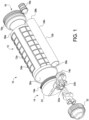
- the dispensing system 10 includes a support cartridge system 12, a two-component collapsible cartridge 14 and piston system 16.
- the dispensing system 10 when filled with a component, can be inserted into a dispensing device to dispense the component or components, as is known in the art.
- a dispensing system 10 for two-components is configured to hold, store and dispense two separate components.
- the two components can be mixed upon dispensing or at any suitable time.
- Such a two-component dispensing system enables materials or components that would otherwise be stored for a significant time period to be stored and used at a later time.
- the piston and dispensing system 10 described herein can be used in a single component dispensing system, a two-component dispensing system or a multicomponent (more than two) system, if desired.
- the cartridge includes a first generally cylindrical reception chamber (or cartridge) 14a and a second generally cylindrical reception chamber (or cartridge) 14b.
- the reception chambers 14a and 14b are each defined by a cartridge wall 18a and 18b and a common head part 20.
- the common head part 20 preferably forms an end-face or surface 22 and 24 of each of the reception chambers 14a and 14b.
- the ends 26a and 26b of the two cartridge walls 18a and 18b are disposed remote from the head part 20 and are each led together toward the center axis C a and C b of the respective reception chamber 18a and 18b and can be bound together by a respective clamping ring 28a and 28b, or in any other suitable manner, such that the ends are capable of being sealingly closed.
- the first reception chamber 14a has a diameter D 1 that is larger than the diameter D 2 of the second reception chamber 14b; however, the reception chambers 14a and 14b can have the same or substantially the same diameter, or have any diameter desired. That is, the diameters can have any relative size to each other that would enable two separate components or materials to be mixed together in a suitable or desired ratio.
- the ends 30a and 30b of the reception chambers 14a and 14b facing the head part 20 are sealingly and unreleasably connected to the head part 20.
- the head part 20 is injection molded to the ends of the reception chambers 14a and 14b.
- the head part 20 can be formed from a stable-shape plastic, and the cartridge walls 18a and 18b can be formed as multilayer films which are each rolled to a cylindrical shape in their predominantly center regions and are welded or otherwise connected to form a seam 31 at their longitudinal edges thus forming together with the head part 20 the cylindrical reception chambers 18a and 18b.
- the head part 20 preferably includes two outlets 20a and 20b which are connected to the reception chambers 18a and 18b for filling the reception chambers with a filling component or material and for dispensing the filling component or material out of the reception chambers.
- a screw cap 32 can be used to close the outlets.
- Fig. 3 illustrates the reception chambers 14a and 14b in an empty state.
- the reception chambers 14a and 14b, as shown in Fig. 3 have not yet filled with a component, i.e. with the material to be dispensed.
- the cartridge walls 18a and 18b have a substantially cylindrical shape due to the stiffness of the used film material. It is noted that this cylindrical shape represents the expanded state of the reception chambers 14a and 14b with a maximum volume of the reception chambers.
- the cartridge walls 18a and 18b can pushed together or compressed in the longitudinal direction of the reception chambers 14a and 14b before filling with the component.
- this state has been determined to reduce the space need for storing and shipping purposes and reduces the waste of a component filing the reception chambers 14a and 14b.
- the support cartridge system 12 includes first and second support cartridges 12a and 12b that include first and second hollow cylinders 34a and 34b, respectively.
- the first and second hollow cylinders 34a and 34b are sized and configured to receive the first and second reception chambers 14a and 14b and of the two-component collapsible cartridge 14, respectively.
- the first and second hollow cylinders 34a and 34b each have a first opening 36a and 36b and a second opening 38a and 38b.
- the first openings 36a and 36b are configured to receive a respective reception chamber 14a and 14b and the second opposite openings 38a and 38b are configured to receive a respective piston 16a and 16b.
- the first and second reception chambers 14a and 14b and can be pushed into a respective reception opening 36a and 36b until the head part 20 contacts the end of the respective support cartridge12a and 12b.
- the piston system 16 includes first and second pistons 16a and 16b, which generally have the same configuration, with the main difference being size or relative diameter. Thus, only the first piston 16a will be described in detail in view of Figs. 5 and 6.
- Figs. 5 and 6 illustrate a first embodiment of the present invention.
- the piston 16a is preferably generally cylindrical, and sized and configured to tightly fit within the inner peripheral surface 40 of the support cartridge 12a. It is noted that in this embodiment, the piston 16a does not need to form a seal with the support cartridge 12a. However, the piston 16a preferably forms a tight fit with the support cartridge 12a to prevent the reception chamber 14a from being pinched between the support cartridge 12a and the piston 16a.
- the piston 16a has a first portion 42 and a second portion 44.
- the first portion 42 is a rigid portion having a first diameter D 3 , a first end 46 and a second end 48.
- the first end 46 of the rigid portion is disposed in the material dispensing direction DD (i.e., the direction in which the component is dispensed), and the second end 48 is disposed in the opposite direction (filling direction FD).
- the second end 48 of the rigid portion 42 can receive the pressure or force that is required to move the piston through the support cartridge 12a.
- the rigid portion 42 is preferably formed from any suitable plastic or metal that is rigid and does not flex under pressure. However, the rigid portion 42 can be formed from any suitable material.
- the rigid portion 42 includes a first rigid portion 42a and a second rigid portion 42b.
- the first rigid portion 42a is disposed externally of the second portion 44, and the second rigid portion 42b is disposed within the second portion 44.
- the first rigid portion 42a includes a radial outer surface 50 adjacent the second end 48 and the second rigid portion 42b includes a protrusion 52 adjacent the first end 46.
- the radial outer surface 50 includes a skirt 54 or sealing lip extending therefrom in the dispensing direction.
- the skirt 54 preferably extends around the entire circumference of the first rigid portion 42a, but can extend in any suitable or desired manner.
- the skirt 54 preferably extends radially outwardly from the end 56 of the radial outer surface 50 and has a diameter about the same size as the inner diameter of the support cartridge 12a. Accordingly, the skirt 54 is sized and configured to slide within the inner surface of the support cartridge 12a. In this connection, it should be noted that the skirt 54 is configured to fit within the support cartridge 12a in such a way that it does not tilt relative to the dispensing direction DD but also does not seal against the inner surface so that the piston 16a can move within the support cartridge 12a.
- a hole 61 or a plurality of holes can be disposed in the skirt 54 or the rigid body 42 to enable air to pass in a direction opposite to the dispensing direction DD during dispensing.
- the hole 61 may also be used to allow air to pass in the dispensing direction DD during filling of the respective reception chambers 14a and 14b, i.e. the air is allowed to pass in an direction opposite to the filling direction FD.
- Such a structure prevents air from being trapped between the piston 16a and the reception chamber 14a, while allowing a tight fit between the skirt 54 and the inner peripheral surface 40 of the support cartridge 12a.
- the skirt 54 preferably extends in the material dispensing direction so to be capable of fitting a portion of or the entire cartridge wall 18a (in the collapsed state) between an inner surface 58 thereof and the second portion 42 (See Fig. 8 ).
- the radial outer surface 50 of the first rigid portion 42a and the outer surface 60 of the skirt 54 also includes a plurality of integrated ribs or tabs 62 spaced radial therearound.
- the tabs 62 generally protrude from the radial outer surface 50 of the rigid portion 42 and the outer surface 60 of the skirt 54 and extend in a longitudinal direction of the dispensing direction DD.
- the radial outer surface 50 and the outer surface 60 of the skirt 54 includes four tabs 62 evenly spaced therearound; however, it is noted that there can be any suitable number of tabs 62, and the tabs 62 can be spaced in any suitable manner. As shown in Fig.
- the tabs 62 can be rectangular in shape and can extend from the second end 48 of the rigid portion 42 to the end 64 of the skirt 54.
- the tabs 62 prevent the cartridge wall 18a, when being compressed, to pass over the end 64 of the skirt 54 of the piston 16a.
- portions of the cartridge wall 18a can be pinched and broken between the piston 16a and the support cartridge 12a. If the cartridge wall 18a is compromised in this manner, a new flow path for the component or material can be formed, creating an undesirable ballooning effect behind the piston 16a.
- the protrusion 52 is preferably cylindrical and has a diameter that is less than the diameter of the end 64 of the skirt 54.
- the protrusion 52 can include an arcuate edge 66 that extends from the edge formed by the first end 46 and the upper radial surface 68 of the second rigid portion 42b. This protrusion 52 increases the support at the edge 66 and guides the cartridge wall 18a to allow the cartridge wall 18a to fit the piston geometry, furthering the amount of material to be dispensed out of the two-component collapsible cartridge 14.
- the second portion 44 is a flexible portion having a second diameter D 4 that is less than the diameter D 3 of the first rigid portion 42a, a first end 68 disposed in the material dispensing direction DD and a second end 70 disposed in the opposite direction (filling direction FD).
- the flexible portion 44 is disposed on the first end 46 of the rigid portion 42 such that the second end 70 of the flexible portion 44 is disposed to face the first end 46 of the rigid portion 42.
- the flexible portion 44 is formed from a material that is capable of radially expanding and longitudinally compressing upon a force applied to the first end 68 of the flexible portion 44 so as to compress the collapsible cartridge between the flexible portion 44 and the surface 22 of the support cartridge 12a.
- the flexible portion 44 can be formed any material suitable to accomplish sufficient radial expansion. Suitable materials can include, but are not limited to thermoplastic elastomer (TPE), silicone, any other elastomeric material or any suitable flexible material.
- TPE thermoplastic elastomer
- silicone any other elastomeric material or any suitable flexible material.
- the flexible portion 44 is formed from a material having a durometer between about 15 and 60 on the durometer A scale.
- the flexible material is formed from a material having a durometer around 25 shore A.
- the flexible portion 44 includes an internal cavity 72 and at least a portion of the rigid portion 42 extends into the internal cavity 72.
- the flexible portion 44 has a recessed portion that defines an integral cavity 72 that is sized and configured to receive the rigid portion 42.
- this embodiment increases the support at the edge and guides the cartridge wall 18a to allow the cartridge wall 18a to fit the piston geometry, furthering the amount of material to be dispensed out of the two-component collapsible cartridge 14.
- the overall height of the flexible portion 44 relative to the cartridge wall 18a length should be determined such that the flexible portion 44 makes initial contact with the end surface 22 of the head part 20 about 1-2 mm prior to the cartridge wall 18a reaching its compressed height. Such a compression distance will generally result in sufficient radially expansion to compress the cartridge wall 18a. However, the deflection of the flexible portion 44 close to the edges is reduced due to the protrusion 52 as discussed above, otherwise the tension of the cartridge wall 18a in this area may cause a larger than desired diameter. Such an increased diameter can trap material and air on the inside of the cartridge wall 18a which is undesirable.
- the cavity 72 of the flexible portion 44 forms a recess 71 that receives the protrusion 52 of the rigid portion 42.
- the protrusion 52 is received in the recess 71 in a form fit manner. Receiving the protrusion 52 in the recess 71 allows for a secure seating of the flexible portion 44 on the rigid portion 42. Furthermore, on compression of the flexible portion 44 in the dispensing direction DD, the protrusion 52 received in the recess 71 prevents that the flexible portion 44 excessively expands in the radial direction. Simultaneously, the flexible portion 44 is directed into the dispensing direction DD and exerts a force on the cartridge 14 so that more material is dispensed therefrom.
- the flexible material or the flexible portion 44 is longitudinally compressed and radially expanded.
- the flexible portion 44 can be flattened against the end surface 22 of the head part 20, which results in expansion of the diameter of the flexible portion 44 in the radial direction.
- the flexible material of the flexible portion 44 increases in diameter by about 1-3 mm in the radial direction RD when a force of approximately 250N is applied to the first end 68.
- the diameter of the flexible portion (44, 144) increases from 2 to 15 % when a force of 250 N is applied to the flexible portion (44, 144), in particular with the force being applied to the flexible portion in a direction that is at least approximately parallel to the dispensing direction DD.
- the flexible portion 44 increases in diameter about 2 mm in the radial direction RD. This radial expansion compresses the cartridge wall 18a of the compressed cartridge between a radial outer surface 74 of the flexible portion 44 and the inner surface 40 of the support sleeve 12a, and/or the inner surface 58 the skirt 54. This structure reduces residual waste or air entrapment in the cartridge.
- the first end 68 of the flexible portion 44 can have any suitable configuration.
- the first end 68 can be generally or substantially flat or planar, it can also have an arcute or curved configuration or it can have a peaked or angled configuration.
- the radial outer surface 74 of the flexible portion 44 can be generally parallel to the longitudinal axis L of the piston 16a or in can form an angle with the longitudinal axis L. That is, the diameter D 4 of the flexible portion 44 at the radial outer surface 74 can decrease in the dispensing direction. That is the diameter D 4 of the flexible portion 44 can decrease in the dispensing direction DD.
- the height Hi of the flexible portion 44 (from the point where the skirt meets the radial outer surface 73 of the rigid member) is between about 12 and 15 mm, and preferably about 14.2 mm.
- the thickness T 1 of the flexible portion from the radial outer surface 73 of the first rigid portion 42a (i.e., the radial inner surface of the flexible portion 44) to the radial outer surface 74 of the flexible portion 44 is about 1.9 mm to about 5.2 mm, and preferably about 3.8 mm.
- the thickness T 2 of the flexible portion 44 from the protrusion 52 of the second rigid portion 42a to the first end 58 of the flexible portion 44 is between about 6.3 mm and 3.2 mm.
- the thickness T 3 of the flexible portion 44 from the first end 46 of the rigid portion 42 to the first end 68 of the flexible portion 44 is between about 6.5 mm and 8.3 mm.
- the ratio of a height Hi of the flexible portion 44 to the distance from the first end 46 of the rigid portion 42 to the first end 68 of the flexible portion 44 is between about 0.5 to 0.55.
- the height H 2 of the flexible portion 44 from the end 64 of the skirt 54 to the first end 68 of the flexible portion is about 7-9 mm.
- the dimensions are merely examples and the dimensions of the flexible portion 44 relative to the rigid portion 42, and any other dimension can be any suitable dimension.
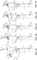
- Figs. 7A-7E the manner in which the two-component collapsible cartridge 14 can be filled is illustrated.
- the two-component collapsible cartridge 14 is shipped to the distributor or user in an empty state.
- the empty two-component collapsible cartridge 14 is connected to the support cartridge system 12, and then as shown in Fig. 7B , inserted into a filling device D.
- the filling device D includes a mounting mechanism M that is configured to attach to the head part 20 to hold the two-component collapsible cartridge 14 in a desired and proper position.
- the piston system 16 is inserted into the support cartridge system 12.
- the piston system 16 is acted upon by force from a plurality of plungers P.
- the force F exerted by each plunger P can be any suitable amount (e.g., 250 N), and supplied in any manner desired, for example using compressed air, a mechanical force or any other suitable device.
- the piston system 16 moves in the dispensing direction toward the end surface of the head part 20. As the piston system 16 moves in this direction, each piston 16a in the piston system 16 enters the open end 80 of a respective cartridge wall 18a and 18b. The edge 82 of each of the cartridge wall 18a and 18b is collected in the area between the skirt 54 and the outer radial surface 74 of the flexible portion 44.
- the heights H 1 and H 2 can be important here, since such heights can affect the amount air or component that is dispensed or expelled from the reception chambers 14a and 14b. As the piston system 16 continues to move and collect the cartridge walls 18a and 18b air is expelled from the cartridges.
- the piston system 16 continues to move in the dispensing direction DD and contacts the end surfaces 22 and 24 of the head part 20. As the piston system 16 contacts these surfaces 22 and 24, the force F is maintained in the dispensing direction DD, thereby causing the flexible portion 44 of each of the pistons 16a and 16b to be compressed in the longitudinal direction L against the surfaces 22 and 24 of the head part 20. This compression causes the flexible portion 44 of each piston to radial expand in the radial direction.
- the radial expansion can be about 1-3 mm (or more preferably about 2 mm) when a force of approximately 250N is applied to the first end 68; however, it is noted that the radial expansion can be any suitable amount. As shown in Fig.
- the radial expansion occurs in the area in which the cartridge wall 18a has been gathered, thus compressing the cartridge wall 18a between the radial outer surface 74 of the flexible portion 44 and the inner surface 40 of the support sleeve 16a, and/or the inner surface 58 of the skirt 54. This compression expels additional air from the collapsed cartridge.
- the filing nozzle N is then attached to the head part 20 and the desired components can be injected or dispensed into the cartridge walls 18a and 18b.
- the force F of the filling nozzle N expands the cartridge walls 18a and 18b and pushes the piston system 16 in the filling direction FD (opposite the dispensing direction), as shown in Fig. 7D .
- the force F of the plungers P can be removed, such that the filling nozzle N is only required to overcome the static force of the plungers P and expansion of the cartridge walls 18a and 18b.
- the limit switches LS the filling nozzle N can be stopped.
- the dispensing system 10 can then be removed and closed.
- the two-component collapsible cartridge 14 is simply inserted into the dispensing device and dispensed.
- the dispensing can be performed using the piston system 16 described herein, which would gather the cartridge walls 18a and 18b in the area between the skirts 54a and the radial outer surfaces 74 and dispense the components in a similar manner to the filing described above. That is, as the piston system 16 continues to move through the support cartridge system 12, the collapsible cartridge walls 18a and 18b are collected, and the components are dispensed through the head part 20. The piston system 16 then continues to move in the dispensing direction DD and contacts the end surfaces 22 and 24 of the head part 20.
- the force F (e.g., 250 N) is maintained in the dispensing direction DD, thereby causing the flexible portion 44 of each piston 16a and 16b to be compressed in the longitudinal direction L against the surfaces 22 and 24 of the head part 20.
- This compression causes the flexible portion 44 of each piston 16a and 16b to radial expand.
- the radial expansion can be about 1-3 mm (or more preferably about 2 mm) when a force of approximately 250N is applied to the first end 68; however, it is noted that the radial expansion can be any suitable amount.
- the radial expansion occurs in the area in which the cartridge walls 18a and 18b have been gathered, thus compressing the cartridge walls 18a and 18b between the radial outer surface 74 of the flexible portion 44 and the inner surface 40 of the support sleeves 12a and 12b, and/or the inner surface 58 of the skirts 54. This compression expels additional component from the collapsed cartridge.
- the piston structure described herein improves the amount of component that can be dispensed by both removing excess air during the filling procedure and expelling additional component during the dispensing procedure. Such a system reduces waste of components, thereby reducing cost and environmental impact.
- Fig. 9 is a partial cross-sectional view of a second embodiment or a piston 116.
- the skirt 154 is attached to the flexible portion 144. That is, the flexible portion 144 includes a first portion 144a and second portion 144b. The first portion 144a is tubular and is connected to the rigid portion 142 at an outer radial 152 surface thereof. The second portion 144b generally comprises the compressible/flexible portion 146 that operates in the same manner as the flexible portion 144 described herein.
- the skirt 154 in this embodiment, is attached to a transverse portion 148 between the first and second portions 144a and 144b and extends in the dispensing direction DD.
- the second portion 144b preferably has a height between about 9.5 mm and 12.9 mm.
- the piston 116 operates in the same manner as described herein for the pistons 16a and 16b of the first embodiment.
- the rigid portion 142 as shown in Fig. 9 has no protrusion 52 like the rigid portion 42 shown in Fig. 5 and 6
- the rigid portion 142 may comprise a protrusion 52 similar to that of the rigid portion 42, with such a protrusion 52 being received in the cavity 71 of the flexible portion 144.
- the dispensing device, into which the present dispensing system is inserted to affect dispensing and the filling device are conventional components that are well known in the art. Since the dispensing device and the filling device are well known in the art, these structures will not be discussed or illustrated in detail herein. Rather, it will be apparent to those skilled in the art from this disclosure that the components can be any type of structure and/or include any programming that can be used to carry out the present invention.
- the term "comprising" and its derivatives, as used herein, are intended to be open ended terms that specify the presence of the stated features, elements, components, groups, integers, and/or steps, but do not exclude the presence of other unstated features, elements, components, groups, integers and/or steps.
- the foregoing also applies to words having similar meanings such as the terms, “including”, “having” and their derivatives.
- the terms "part,” or “portion,” when used in the singular can have the dual meaning of a single part or a plurality of parts.
- the following directional terms refer to those directions of a system equipped with the piston for a collapsible cartridge. Accordingly, these terms, as utilized to describe the present invention should be interpreted relative to a system equipped with the piston for a collapsible cartridge.
Landscapes
- Engineering & Computer Science (AREA)
- Mechanical Engineering (AREA)
- Containers And Packaging Bodies Having A Special Means To Remove Contents (AREA)
- Coating Apparatus (AREA)
- Package Specialized In Special Use (AREA)
Claims (13)
- Abgabesystem (10), umfassend:eine Kartusche (14) mit einem Kopfteil (20) und einer Kartuschenwand (18a, 18b), die eine Aufnahmekammer (14a, 14b) definieren, die konfiguriert ist, um ein abzugebendes Medium zurückzuhalten, wobei der Kopfteil (20) eine Oberfläche (22, 24) und einen Auslass (20a, 20b) in der Oberfläche (22, 24) umfasst, wobei der Auslass (20a, 20b) konfiguriert ist, um zu ermöglichen, dass das Material dadurch abgegeben wird, wobei die Kartuschenwand (18a, 18b) so konfiguriert ist, dass sie zusammenlegbar ist; undeinen Kolben (16a, 16b, 116), der konfiguriert ist, um die Kartusche (14) zusammenzulegen und das Medium abzugeben, wobei der Kolben (16a, 16b, 116) einen starren Abschnitt (42, 142) mit einem ersten Durchmesser (D3), einem ersten Ende (46) und einem zweiten Ende (48), wobei das erste Ende (46) konfiguriert ist, um in einer Materialabgaberichtung (DD) angeordnet zu sein, und einen flexiblen Abschnitt (44, 144) mit einem zweiten Durchmesser (D4) umfasst, der kleiner als der erste Durchmesser (D3) ist, wobei ein erstes Ende (68) in der Materialabgaberichtung (DD) angeordnet ist und das zweite Ende (70) in einer entgegengesetzten Richtung angeordnet ist, wobei der flexible Abschnitt (44, 144) auf dem ersten Ende (46) des starren Abschnitts (42, 142) angeordnet ist, so dass das zweite Ende (70) des flexiblen Abschnitts (44, 144) angeordnet ist, um dem ersten Ende (46) des starren Abschnitts (42, 142) zugewandt zu sein, und wobei der flexible Abschnitt (44, 144) konfiguriert ist, um sich bei einer Kraft, die auf den Kolben (16a, 16b, 116) in der Materialabgaberichtung (DD) ausgeübt wird, radial auszudehnen, so dass das erste Ende (68) des flexiblen Abschnitts (44, 144) mit der Oberfläche (22, 24) des Kopfteils (20) in Kontakt tritt.
- Abgabesystem (10) nach Anspruch 1, wobei
der flexible Abschnitt (44, 144) konfiguriert ist, um sich bei einer Kraft, die auf den Kolben (16a, 16b, 116) in der Materialabgaberichtung (DD) ausgeübt wird, zwischen etwa 1 mm und 3 mm radial auszudehnen, so dass das erste Ende (68) des flexiblen Abschnitts (44, 144) mit der Oberfläche (22, 24) des Kopfteils (20) in Kontakt tritt. - Abgabesystem (10) nach einem der Ansprüche 1 oder 2, wobeider Kolben (16a, 16b, 116) eine Schürze (54, 154) auf mindestens einem von dem starren Abschnitt (42, 142) und dem flexiblen Abschnitt (44, 144) umfasst und die Kartusche (14) konfiguriert ist, um sich bei Kompression der Kartusche (14) in der Schürze (54, 154) zu sammeln, wobei insbesonderedie Schürze (54, 154) eine Lasche (62) auf einer Außenfläche (60) umfasst und/oder wobei insbesondere mindestens ein Loch (61) in der Schürze (54, 154) angeordnet ist.
- Abgabesystem (10) nach einem der Ansprüche 1 bis 3, wobei
das erste Ende (68) des flexiblen Abschnitts (44, 144) planar, gekrümmt, spitz zulaufend oder abgewinkelt ist. - Abgabesystem (10) nach einem der vorhergehenden Ansprüche, wobei
der zweite Durchmesser (D4) des flexiblen Abschnitts (44, 144) in der Materialabgaberichtung (DD) abnimmt. - Abgabesystem (10) nach einem der vorhergehenden Ansprüche, wobeider flexible Abschnitt (44, 144) einen inneren Hohlraum (72) umfasst und sich mindestens ein Abschnitt des starren Abschnitts (42, 142) in den inneren Hohlraum (72) erstreckt; und/oder wobeidas erste Ende (46) des starren Abschnitts (42, 142) einen Vorsprung (52) an seinem Umfangsrand umfasst, wobei insbesondereder Hohlraum (72) des flexiblen Abschnitts (44, 144) eine Ausnehmung (71) bildet, die den Vorsprung (52) des starren Abschnitts (42, 142) aufnimmt;
und/oder wobeider flexible Abschnitt (44, 144) einen inneren Hohlraum (72) umfasst und sich mindestens ein Abschnitt des starren Abschnitts (42, 142) in den inneren Hohlraum (72) erstreckt, so dass das Verhältnis einer Höhe des flexiblen Abschnitts (44, 144) zu der Distanz von dem ersten Ende (46) des starren Abschnitts (42, 142) zu dem ersten Ende (68) des flexiblen Abschnitts (44, 144) zwischen etwa 0,5 bis 0,55 liegt; und/oder wobeider flexible Abschnitt (44, 144) aus einem Material mit einem Durometer zwischen etwa 15 und 60 gebildet ist, so dass das flexible Material konfiguriert ist, um sich bei dem Kontakt mit der Oberfläche (22, 24) des Kopfteils (20) zwischen 1 mm und 3 mm radial auszudehnen, wenn die Kraft etwa 250 N beträgt; und/oder wobeiein Durchmesser des flexiblen Abschnitts (44, 144) von 2 bis 15 % zunimmt, wenn eine Kraft von 250 N auf den flexiblen Abschnitt (44, 144) ausgeübt wird. - Abgabesystem (10) nach einem der vorhergehenden Ansprüche, wobei
der flexible Abschnitt (44, 144) aus einem elastomeren Material oder einem flexiblen Material, insbesondere aus einem thermoplastischen Elastomer (TPE) oder Silikon, gebildet ist. - Verfahren zum Füllen eines Materials in eine Kartusche (14), wobei das Verfahren umfasst:Zusammenlegen der Kartusche (14) mit einem Kolben (16a, 16b, 116), wobei der Kolben (16a, 16b, 116) einen starren Abschnitt (42, 142) und einen flexiblen Abschnitt (44, 144) aufweist, wobei der flexible Abschnitt (44, 144) am Abgabeende des Kolbens (16a, 16b, 116) angeordnet ist;Ausüben einer Kraft auf den Kolben (16a, 16b, 116), so dass der flexible Abschnitt (44, 144) des Kolbens (16a, 16b, 116) mit einer Oberfläche (22, 24) eines Kopfteils (20) der Kartusche (14) in Kontakt tritt, was bewirkt, dass ein Durchmesser des flexiblen Abschnitts (44, 144) radial zunimmt;Zusammendrücken der Kartusche (14) zwischen einer radialen Außenfläche (74) des flexiblen Abschnitts (44, 144) und einer Innenfläche eines Kartuschenträgers (12a, 12b); undHinzufügen des Materials durch eine Öffnung im Kopfteil (20), was bewirkt, dass sich der Kolben (16a, 16b, 116) in einer Richtung weg vom Kopfteil (20) bewegt.
- Verfahren nach Anspruch 8, wobei
das Zusammenlegen der Kartusche (14) das Sammeln der Kartusche (14) in einer Schürze (54, 154) umfasst, die an dem Kolben (16a, 16b, 116) angeordnet ist. - Verfahren nach einem der Ansprüche 8 oder 9, wobei
das Ausüben der Kraft auf den Kolben (16a, 16b, 116) das Ausüben einer Kraft von etwa 250 N umfasst, was bewirkt, dass der Durchmesser des flexiblen Abschnitts (44, 144) zwischen etwa 1 mm bis 3 mm zunimmt, um Luft aus der Kartusche (14) auszustoßen. - Verfahren zum Abgeben eines Materials aus einer Kartusche, das die Schritte umfasst:Bereitstellen eines Abgabesystems (10) nach einem der Ansprüche 1 bis 7, undAusüben einer zweiten Kraft auf den Kolben (16a, 16b, 116), um das Material durch die Öffnung im Kopfteil (20) abzugeben.
- Verfahren nach Anspruch 11, wobeidas Ausüben der zweiten Kraft auf den Kolben (16a, 16b, 116) bewirkt,dass die Kartusche (14) in einer Schürze (54, 154) gesammelt wird, die auf dem Kolben (16a, 16b, 116) angeordnet ist.
- Verfahren nach einem der Ansprüche 11 oder 12, wobeidas Ausüben der zweiten Kraft auf den Kolben (16a, 16b, 116) bewirkt,dass der flexible Abschnitt (44, 144) mit der Oberfläche (22, 24) des Kopfteils (20) in Kontakt tritt und der Durchmesser des flexiblen Abschnitts (44, 144) radial zunimmt und eine radiale Umfangsfläche des flexiblen Abschnitts (44, 144) mit einem Abschnitt der Kartusche (14) in Kontakt tritt, um das Material durch die Öffnung im Kopfteil (20) abzugeben.
Applications Claiming Priority (2)
| Application Number | Priority Date | Filing Date | Title |
|---|---|---|---|
| US15/855,357 US10968031B2 (en) | 2017-12-27 | 2017-12-27 | Piston for a collapsible cartridge |
| PCT/EP2018/086391 WO2019129664A1 (en) | 2017-12-27 | 2018-12-20 | Piston for a collapsible cartridge |
Publications (2)
| Publication Number | Publication Date |
|---|---|
| EP3710173A1 EP3710173A1 (de) | 2020-09-23 |
| EP3710173B1 true EP3710173B1 (de) | 2024-10-23 |
Family
ID=64949288
Family Applications (1)
| Application Number | Title | Priority Date | Filing Date |
|---|---|---|---|
| EP18829850.9A Active EP3710173B1 (de) | 2017-12-27 | 2018-12-20 | Kolben für eine zusammenlegbare kartusche |
Country Status (6)
| Country | Link |
|---|---|
| US (3) | US10968031B2 (de) |
| EP (1) | EP3710173B1 (de) |
| JP (1) | JP7189220B2 (de) |
| KR (1) | KR102475141B1 (de) |
| CN (1) | CN111741819B (de) |
| WO (1) | WO2019129664A1 (de) |
Families Citing this family (8)
| Publication number | Priority date | Publication date | Assignee | Title |
|---|---|---|---|---|
| EP3263483A1 (de) * | 2016-07-01 | 2018-01-03 | Sulzer Mixpac AG | Kartusche, kern, form und verfahren zur herstellung einer kartusche |
| US10968031B2 (en) | 2017-12-27 | 2021-04-06 | Sulzer Mixpac Ag | Piston for a collapsible cartridge |
| US20200070189A1 (en) * | 2018-08-30 | 2020-03-05 | Nordson Corporation | Adapter mixer attachment |
| EP3632575A1 (de) * | 2018-10-02 | 2020-04-08 | Sulzer Mixpac AG | Wiederverwendbarer kartuschenkolben |
| EP3714994A1 (de) * | 2019-03-26 | 2020-09-30 | Sulzer Mixpac AG | Kolben, kartusche, spender |
| CN112293380B (zh) * | 2020-10-23 | 2022-03-25 | 北京市疾病预防控制中心 | 一种蚊虫抗药性检测筒 |
| US11951506B2 (en) * | 2022-09-08 | 2024-04-09 | Hamilton Sundstrand Corporation | Two part applicator pen |
| WO2025149764A1 (en) | 2024-01-09 | 2025-07-17 | Fazekas Gabor | Cartridge, shoulder element and manufacturing method therefor |
Family Cites Families (74)
| Publication number | Priority date | Publication date | Assignee | Title |
|---|---|---|---|---|
| US2361647A (en) | 1942-05-20 | 1944-10-31 | Nyden Robert | Collapsible dispensing tube |
| US3323682A (en) | 1965-10-06 | 1967-06-06 | Chem Dev Corp | Disposable cartridge for gun-type dispensers |
| US4231492A (en) * | 1978-03-14 | 1980-11-04 | Oatey Co. | Apparatus and method for dispensing putty-like material |
| US4312344A (en) | 1980-04-03 | 1982-01-26 | Kenova Ab | Syringe |
| GB2090336B (en) * | 1980-12-29 | 1984-08-01 | Toray Silicone Co | Caulking gun using bagged sealer |
| US4411656A (en) | 1982-01-29 | 1983-10-25 | Urologic & Enteric Research Associates | Compressible syringe |
| DE3344345A1 (de) | 1983-12-08 | 1985-06-13 | Henkel KGaA, 4000 Düsseldorf | Verpackungssystem |
| EP0150894B1 (de) | 1984-01-06 | 1988-05-18 | THE PROCTER & GAMBLE COMPANY | Flexible Behälter, die ein flüssiges Produkt enthalten, und Verhinderung eines Vakuum-Kollapses in den Behältern |
| FR2596022B1 (fr) | 1986-03-24 | 1989-01-06 | Clanet Frank | Piston souple et gonflable pour conteneur bi- ou pluricompartimental |
| US4907727A (en) * | 1988-10-31 | 1990-03-13 | Illinois Tool Works, Inc. | Dispensing device having improved plunger assemblies |
| DE9200521U1 (de) * | 1991-11-12 | 1993-03-25 | Thera Patent GmbH & Co KG Gesellschaft für industrielle Schutzrechte, 8031 Seefeld | Behälter für fließfähige Substanzen |
| US5447110A (en) | 1992-07-24 | 1995-09-05 | Brown; Wesley J. | Collapsible container |
| US5301835A (en) * | 1992-09-17 | 1994-04-12 | Dow Corning Corporation | Adapter for dispensing material from a sausage type package |
| PH31484A (en) * | 1992-12-22 | 1998-11-03 | Hosokawa Yoko Kk | Container, method of manufacturing the same and installation jig for cartridge container for d18scharge gun. |
| JPH08502712A (ja) | 1993-08-20 | 1996-03-26 | アー. ケラー,ヴィルヘルム | 折りたためるカートリッジを備えた多成分計量および相対比例配分装置 |
| US5386928A (en) | 1993-11-15 | 1995-02-07 | Minnesota Mining And Manufacturing Company | Dual collapsible tube dispensing assembly |
| US5566860A (en) | 1994-09-08 | 1996-10-22 | Liquid Control Corporation | Dual component cartridge |
| JPH08266991A (ja) * | 1995-04-04 | 1996-10-15 | Yokohama Rubber Co Ltd:The | シーリング材パック用コーキングガンのパック穿孔治具 |
| DE19536902A1 (de) | 1995-10-04 | 1997-04-10 | Boehringer Ingelheim Int | Vorrichtung zur Hochdruckerzeugung in einem Fluid in Miniaturausführung |
| US5680967A (en) * | 1996-09-13 | 1997-10-28 | Courtaulds Aerospace, Inc. | Dispensing cartridge |
| DE69736448T2 (de) * | 1996-12-24 | 2007-01-04 | Mixpac Systems Ag | Dünnwandige Verpackung zur Verwendung in einer Kartusche |
| FR2765560B1 (fr) | 1997-07-02 | 1999-08-13 | Oreal | Distributeur pour un produit liquide ou pateux comportant des moyens de pompage ameliores |
| US6004300A (en) | 1997-08-28 | 1999-12-21 | Butcher; Robert M | Composite hypodermic syringe piston |
| US6286725B1 (en) | 1997-09-19 | 2001-09-11 | Waterfall Company, Inc. | Contamination-safe multi-dose dispensing and delivery system for flowable materials |
| SE9704769D0 (sv) | 1997-12-19 | 1997-12-19 | Astra Ab | Medical device |
| EP0992438A1 (de) | 1998-10-09 | 2000-04-12 | Wilhelm A. Keller | Dünnwandige Kartusche für wiederverwendbare Abgabevorrichtung |
| WO2000030703A1 (en) | 1998-11-23 | 2000-06-02 | Medrad, Inc. | Syringes and injector systems with collapsible cartridges |
| US6223941B1 (en) * | 1999-07-19 | 2001-05-01 | The Boeing Company | Applicator for dispensing a soft package of material |
| US6435373B1 (en) | 1999-10-07 | 2002-08-20 | Shalom Mizrahi | Caulking gun and cartridge structure |
| JP2001328652A (ja) | 2000-05-19 | 2001-11-27 | Hosokawa Yoko Co Ltd | 吐出ガン用カートリッジおよび吐出ガン用カートリッジ組立体並びに吐出ガン用カートリッジの製造方法 |
| US6796463B2 (en) | 2001-10-09 | 2004-09-28 | Stewart Boal, Jr. | Inflatable and collapsible apparatus for dispensing fluid from a fluid vessel |
| US7226231B2 (en) | 2003-07-17 | 2007-06-05 | Medical Instill Technologies, Inc. | Piston-type dispenser with one-way valve for storing and dispensing metered amounts of substances |
| JP4573557B2 (ja) | 2004-04-01 | 2010-11-04 | 旭化成ケミカルズ株式会社 | 2液性反応型接着剤用ケース |
| US20060144854A1 (en) * | 2004-12-30 | 2006-07-06 | Plas-Pak Industries, Inc. | Cartridge delivery system utilizing film bags |
| US9517488B2 (en) * | 2004-12-30 | 2016-12-13 | Plas-Pak Industries, Inc. | Component delivery system utilizing film bags |
| US7690530B2 (en) * | 2005-05-06 | 2010-04-06 | Albion Engineering Company | Dispenser for viscous material |
| US8087550B2 (en) * | 2006-04-07 | 2012-01-03 | Albion Engineering Company | Convertible device for dispensing material having parts that can be retained on the device |
| WO2008063222A2 (en) | 2006-05-11 | 2008-05-29 | Dentsply International Inc. | Aerosol delivery system for dispensing dental compositions |
| JP4855171B2 (ja) * | 2006-07-28 | 2012-01-18 | キユーピー株式会社 | 粘性液状物のためのガン式ディスペンサ |
| DE102008000841B8 (de) * | 2008-03-26 | 2014-07-10 | Adcatec Gmbh | Kartusche und Kolben mit Entlüftungsvorrichtung |
| US8424727B2 (en) | 2008-05-05 | 2013-04-23 | Meritool Llc | Material dispensing assembly |
| US8235255B2 (en) * | 2008-07-02 | 2012-08-07 | Nordson Corporation | Pistons with a lip seal and cartridge systems using such pistons |
| PL2361175T3 (pl) | 2008-10-23 | 2017-05-31 | The Procter & Gamble Company | Sposób wytwarzania systemu dozowania materiału |
| TW201029897A (en) | 2008-12-12 | 2010-08-16 | Sulzer Mixpac Ag | Cartridge piston |
| JP5550638B2 (ja) | 2009-04-21 | 2014-07-16 | テルモ株式会社 | 医療用容器 |
| CN102725615A (zh) | 2009-09-18 | 2012-10-10 | 宝洁公司 | 单位剂量分配设备 |
| ES2617329T3 (es) * | 2009-12-11 | 2017-06-16 | Sulzer Mixpac Ag | Pistón de cartucho |
| DE102010019220B4 (de) * | 2010-05-04 | 2015-03-26 | Heraeus Medical Gmbh | Kartuschensystem mit verbundenen Förderkolben |
| GB201012094D0 (en) * | 2010-07-19 | 2010-09-01 | 2K Polymer Systems Ltd | Multi-component dispenser |
| JP2012056633A (ja) * | 2010-09-13 | 2012-03-22 | Sulzer Mixpac Ag | カートリッジピストン |
| US8544683B2 (en) | 2010-10-29 | 2013-10-01 | Nordson Corporation | Multiple component dispensing cartridge and method with side-by-side fluid chambers |
| EP2468416A1 (de) * | 2010-12-24 | 2012-06-27 | Sika Technology AG | Applikationsvorrichtung für Mehrkomponentenstoffe, ein Kartuschenset und eine Verpackungseinheit |
| DE102011010763B4 (de) | 2011-02-10 | 2013-03-14 | Frank Wolff | Mehrkammer-Kartuschen-Vorrichtung |
| EP2497721B1 (de) * | 2011-03-11 | 2013-11-20 | Sulzer Mixpac AG | Mehrkomponentenkartusche |
| WO2012145343A2 (en) | 2011-04-18 | 2012-10-26 | Kuvio, Inc. | Drug delivery device with compressible fluid chambers |
| EP2546166B1 (de) * | 2011-07-15 | 2014-05-14 | Sulzer Mixpac AG | Kolbensicherung |
| US8763829B2 (en) | 2011-07-22 | 2014-07-01 | Craig Allen Madaus | Collapsible container for holding liquids or objects |
| US8426270B2 (en) | 2011-07-22 | 2013-04-23 | Intermolecular, Inc. | Memory device with a textured lowered electrode |
| CN103998149B (zh) | 2011-10-17 | 2017-03-29 | 苏舍米克斯帕克有限公司 | 筒和多组分筒 |
| CN103998148B (zh) | 2011-10-17 | 2019-12-31 | 苏舍米克斯帕克有限公司 | 筒、用于制造这样的筒的方法以及多组分筒 |
| JP5101743B1 (ja) | 2012-04-02 | 2012-12-19 | 加賀ワークス株式会社 | 空圧ディスペンサ用プランジャ |
| US9044082B2 (en) | 2012-04-20 | 2015-06-02 | Dart Industries Inc. | Collapsible container |
| US9469061B2 (en) * | 2013-01-30 | 2016-10-18 | Plas-Pak Industries Inc | One-piece ventable piston for a dispensing apparatus, a dispensing apparatus with same, and method of making same |
| US9597706B2 (en) | 2013-03-15 | 2017-03-21 | Rooftop Research, Llc | Container and substance dispensing system |
| US9527106B2 (en) | 2013-10-31 | 2016-12-27 | Nordson Corporation | Applicator and method for dispensing a viscous fluid |
| EP2873465A1 (de) * | 2013-11-18 | 2015-05-20 | Sulzer Mixpac AG | Kolben zum Austragen einer fliessfähigen Komponente aus einer Kartusche |
| CN104648766A (zh) | 2013-11-22 | 2015-05-27 | 宁波三植橡塑科技有限公司 | 一种可折叠容器 |
| EP2927156A1 (de) | 2014-03-31 | 2015-10-07 | Sulzer Mixpac AG | Kartusche und Verfahren zum Herstellen einer Kartusche |
| US9481495B2 (en) | 2014-04-24 | 2016-11-01 | Scholle Ipn Corporation | Dispensing system |
| EP2987601A1 (de) * | 2014-08-21 | 2016-02-24 | Sulzer Mixpac AG | Verfahren zur Herstellung einer Vorrichtung zur Abgabe eines Mediums |
| DE102014112595A1 (de) | 2014-09-02 | 2016-03-03 | Reinhard Caliebe | Dose für ein medizinisches, pharmazeutisches oder kosmetisches Fluid |
| EP2998030A1 (de) | 2014-09-17 | 2016-03-23 | Sulzer Mixpac AG | Kolben für eine Kartusche, Kartusche und Verfahren zur Entlüftung einer Kartusche |
| US9937519B2 (en) | 2016-05-13 | 2018-04-10 | Franke Technology and Trademark, Ltd. | Kit for adapting dispensers to dispense materials from flexible-walled containers |
| US10968031B2 (en) * | 2017-12-27 | 2021-04-06 | Sulzer Mixpac Ag | Piston for a collapsible cartridge |
-
2017
- 2017-12-27 US US15/855,357 patent/US10968031B2/en active Active
-
2018
- 2018-12-20 EP EP18829850.9A patent/EP3710173B1/de active Active
- 2018-12-20 WO PCT/EP2018/086391 patent/WO2019129664A1/en not_active Ceased
- 2018-12-20 US US16/956,821 patent/US11414260B2/en active Active
- 2018-12-20 KR KR1020207021845A patent/KR102475141B1/ko active Active
- 2018-12-20 JP JP2020536011A patent/JP7189220B2/ja active Active
- 2018-12-20 CN CN201880090387.0A patent/CN111741819B/zh active Active
-
2022
- 2022-04-27 US US17/730,686 patent/US11780667B2/en active Active
Also Published As
| Publication number | Publication date |
|---|---|
| EP3710173A1 (de) | 2020-09-23 |
| JP2021508592A (ja) | 2021-03-11 |
| KR102475141B1 (ko) | 2022-12-07 |
| CN111741819A (zh) | 2020-10-02 |
| BR112020013055A8 (pt) | 2023-03-21 |
| US11780667B2 (en) | 2023-10-10 |
| US10968031B2 (en) | 2021-04-06 |
| US20190193919A1 (en) | 2019-06-27 |
| WO2019129664A1 (en) | 2019-07-04 |
| US20200399045A1 (en) | 2020-12-24 |
| CN111741819B (zh) | 2022-08-02 |
| JP7189220B2 (ja) | 2022-12-13 |
| BR112020013055A2 (pt) | 2020-12-01 |
| KR20200101973A (ko) | 2020-08-28 |
| US11414260B2 (en) | 2022-08-16 |
| US20220411169A1 (en) | 2022-12-29 |
Similar Documents
| Publication | Publication Date | Title |
|---|---|---|
| EP3710173B1 (de) | Kolben für eine zusammenlegbare kartusche | |
| US8408426B2 (en) | Squeezable partition bottle and bag assembly | |
| KR101767429B1 (ko) | 카트리지 및 카트리지의 제조 방법 | |
| US9113981B2 (en) | Ejection device and method of filling the ejection device with a material | |
| US5065906A (en) | Double-chambered cartridge having semi-cylindrical pistons for use in a press-out gun | |
| US5509584A (en) | Head for dispensing a product, particularly a pasty product, and dispenser equipped with this head | |
| KR20140145995A (ko) | 액체 투여 주사기 및 피스톤 바운스를 감소시키는 방법 | |
| CN109328172B (zh) | 料筒、芯部、模具和制造料筒的方法 | |
| EP3448777A1 (de) | Kartusche, kern, form und verfahren zur herstellung einer kartusche | |
| US10518956B2 (en) | Assembly comprising a foil pack and a dispensing device and foil pack | |
| CN101065298B (zh) | 多成分喷敷器 | |
| EP3055075B1 (de) | Hülse, abgabevorrichtung mit der hülse und verfahren | |
| BR112020013055B1 (pt) | Pistão para um cartucho retrátil | |
| EP4234104A1 (de) | Kartuschenanordnung zum einsetzen in einen spender und spender zur ausgabe von materialien | |
| CN111918826A (zh) | 多腔筒 | |
| KR20240144365A (ko) | 분배 주사기의 피스톤용 와이퍼 시일 | |
| EP4228824A1 (de) | Kolben für dichtmittelabgabepatronen mit zusammenklappbarer dichtmittelverpackung |
Legal Events
| Date | Code | Title | Description |
|---|---|---|---|
| STAA | Information on the status of an ep patent application or granted ep patent |
Free format text: STATUS: UNKNOWN |
|
| STAA | Information on the status of an ep patent application or granted ep patent |
Free format text: STATUS: THE INTERNATIONAL PUBLICATION HAS BEEN MADE |
|
| PUAI | Public reference made under article 153(3) epc to a published international application that has entered the european phase |
Free format text: ORIGINAL CODE: 0009012 |
|
| STAA | Information on the status of an ep patent application or granted ep patent |
Free format text: STATUS: REQUEST FOR EXAMINATION WAS MADE |
|
| 17P | Request for examination filed |
Effective date: 20200618 |
|
| AK | Designated contracting states |
Kind code of ref document: A1 Designated state(s): AL AT BE BG CH CY CZ DE DK EE ES FI FR GB GR HR HU IE IS IT LI LT LU LV MC MK MT NL NO PL PT RO RS SE SI SK SM TR |
|
| AX | Request for extension of the european patent |
Extension state: BA ME |
|
| DAV | Request for validation of the european patent (deleted) | ||
| DAX | Request for extension of the european patent (deleted) | ||
| RAP3 | Party data changed (applicant data changed or rights of an application transferred) |
Owner name: MEDMIX SWITZERLAND AG |
|
| STAA | Information on the status of an ep patent application or granted ep patent |
Free format text: STATUS: EXAMINATION IS IN PROGRESS |
|
| 17Q | First examination report despatched |
Effective date: 20230627 |
|
| GRAP | Despatch of communication of intention to grant a patent |
Free format text: ORIGINAL CODE: EPIDOSNIGR1 |
|
| STAA | Information on the status of an ep patent application or granted ep patent |
Free format text: STATUS: GRANT OF PATENT IS INTENDED |
|
| INTG | Intention to grant announced |
Effective date: 20240527 |
|
| GRAS | Grant fee paid |
Free format text: ORIGINAL CODE: EPIDOSNIGR3 |
|
| GRAA | (expected) grant |
Free format text: ORIGINAL CODE: 0009210 |
|
| STAA | Information on the status of an ep patent application or granted ep patent |
Free format text: STATUS: THE PATENT HAS BEEN GRANTED |
|
| AK | Designated contracting states |
Kind code of ref document: B1 Designated state(s): AL AT BE BG CH CY CZ DE DK EE ES FI FR GB GR HR HU IE IS IT LI LT LU LV MC MK MT NL NO PL PT RO RS SE SI SK SM TR |
|
| REG | Reference to a national code |
Ref country code: GB Ref legal event code: FG4D |
|
| REG | Reference to a national code |
Ref country code: CH Ref legal event code: EP |
|
| P01 | Opt-out of the competence of the unified patent court (upc) registered |
Free format text: CASE NUMBER: UPC_APP_411786/2023 Effective date: 20230505 |
|
| REG | Reference to a national code |
Ref country code: DE Ref legal event code: R096 Ref document number: 602018075806 Country of ref document: DE |
|
| REG | Reference to a national code |
Ref country code: IE Ref legal event code: FG4D |
|
| REG | Reference to a national code |
Ref country code: LT Ref legal event code: MG9D |
|
| REG | Reference to a national code |
Ref country code: NL Ref legal event code: MP Effective date: 20241023 |
|
| REG | Reference to a national code |
Ref country code: AT Ref legal event code: MK05 Ref document number: 1734418 Country of ref document: AT Kind code of ref document: T Effective date: 20241023 |
|
| PG25 | Lapsed in a contracting state [announced via postgrant information from national office to epo] |
Ref country code: NL Free format text: LAPSE BECAUSE OF FAILURE TO SUBMIT A TRANSLATION OF THE DESCRIPTION OR TO PAY THE FEE WITHIN THE PRESCRIBED TIME-LIMIT Effective date: 20241023 |
|
| PG25 | Lapsed in a contracting state [announced via postgrant information from national office to epo] |
Ref country code: NL Free format text: LAPSE BECAUSE OF FAILURE TO SUBMIT A TRANSLATION OF THE DESCRIPTION OR TO PAY THE FEE WITHIN THE PRESCRIBED TIME-LIMIT Effective date: 20241023 |
|
| PG25 | Lapsed in a contracting state [announced via postgrant information from national office to epo] |
Ref country code: HR Free format text: LAPSE BECAUSE OF FAILURE TO SUBMIT A TRANSLATION OF THE DESCRIPTION OR TO PAY THE FEE WITHIN THE PRESCRIBED TIME-LIMIT Effective date: 20241023 Ref country code: IS Free format text: LAPSE BECAUSE OF FAILURE TO SUBMIT A TRANSLATION OF THE DESCRIPTION OR TO PAY THE FEE WITHIN THE PRESCRIBED TIME-LIMIT Effective date: 20250223 Ref country code: PT Free format text: LAPSE BECAUSE OF FAILURE TO SUBMIT A TRANSLATION OF THE DESCRIPTION OR TO PAY THE FEE WITHIN THE PRESCRIBED TIME-LIMIT Effective date: 20250224 |
|
| PG25 | Lapsed in a contracting state [announced via postgrant information from national office to epo] |
Ref country code: FI Free format text: LAPSE BECAUSE OF FAILURE TO SUBMIT A TRANSLATION OF THE DESCRIPTION OR TO PAY THE FEE WITHIN THE PRESCRIBED TIME-LIMIT Effective date: 20241023 |
|
| PG25 | Lapsed in a contracting state [announced via postgrant information from national office to epo] |
Ref country code: BG Free format text: LAPSE BECAUSE OF FAILURE TO SUBMIT A TRANSLATION OF THE DESCRIPTION OR TO PAY THE FEE WITHIN THE PRESCRIBED TIME-LIMIT Effective date: 20241023 |
|
| PG25 | Lapsed in a contracting state [announced via postgrant information from national office to epo] |
Ref country code: ES Free format text: LAPSE BECAUSE OF FAILURE TO SUBMIT A TRANSLATION OF THE DESCRIPTION OR TO PAY THE FEE WITHIN THE PRESCRIBED TIME-LIMIT Effective date: 20241023 |
|
| PG25 | Lapsed in a contracting state [announced via postgrant information from national office to epo] |
Ref country code: NO Free format text: LAPSE BECAUSE OF FAILURE TO SUBMIT A TRANSLATION OF THE DESCRIPTION OR TO PAY THE FEE WITHIN THE PRESCRIBED TIME-LIMIT Effective date: 20250123 |
|
| PG25 | Lapsed in a contracting state [announced via postgrant information from national office to epo] |
Ref country code: AT Free format text: LAPSE BECAUSE OF FAILURE TO SUBMIT A TRANSLATION OF THE DESCRIPTION OR TO PAY THE FEE WITHIN THE PRESCRIBED TIME-LIMIT Effective date: 20241023 Ref country code: LV Free format text: LAPSE BECAUSE OF FAILURE TO SUBMIT A TRANSLATION OF THE DESCRIPTION OR TO PAY THE FEE WITHIN THE PRESCRIBED TIME-LIMIT Effective date: 20241023 Ref country code: GR Free format text: LAPSE BECAUSE OF FAILURE TO SUBMIT A TRANSLATION OF THE DESCRIPTION OR TO PAY THE FEE WITHIN THE PRESCRIBED TIME-LIMIT Effective date: 20250124 |
|
| PG25 | Lapsed in a contracting state [announced via postgrant information from national office to epo] |
Ref country code: PL Free format text: LAPSE BECAUSE OF FAILURE TO SUBMIT A TRANSLATION OF THE DESCRIPTION OR TO PAY THE FEE WITHIN THE PRESCRIBED TIME-LIMIT Effective date: 20241023 |
|
| PG25 | Lapsed in a contracting state [announced via postgrant information from national office to epo] |
Ref country code: RS Free format text: LAPSE BECAUSE OF FAILURE TO SUBMIT A TRANSLATION OF THE DESCRIPTION OR TO PAY THE FEE WITHIN THE PRESCRIBED TIME-LIMIT Effective date: 20250123 |
|
| PG25 | Lapsed in a contracting state [announced via postgrant information from national office to epo] |
Ref country code: SM Free format text: LAPSE BECAUSE OF FAILURE TO SUBMIT A TRANSLATION OF THE DESCRIPTION OR TO PAY THE FEE WITHIN THE PRESCRIBED TIME-LIMIT Effective date: 20241023 |
|
| PG25 | Lapsed in a contracting state [announced via postgrant information from national office to epo] |
Ref country code: MC Free format text: LAPSE BECAUSE OF FAILURE TO SUBMIT A TRANSLATION OF THE DESCRIPTION OR TO PAY THE FEE WITHIN THE PRESCRIBED TIME-LIMIT Effective date: 20241023 |
|
| PG25 | Lapsed in a contracting state [announced via postgrant information from national office to epo] |
Ref country code: DK Free format text: LAPSE BECAUSE OF FAILURE TO SUBMIT A TRANSLATION OF THE DESCRIPTION OR TO PAY THE FEE WITHIN THE PRESCRIBED TIME-LIMIT Effective date: 20241023 |
|
| PG25 | Lapsed in a contracting state [announced via postgrant information from national office to epo] |
Ref country code: EE Free format text: LAPSE BECAUSE OF FAILURE TO SUBMIT A TRANSLATION OF THE DESCRIPTION OR TO PAY THE FEE WITHIN THE PRESCRIBED TIME-LIMIT Effective date: 20241023 |
|
| PG25 | Lapsed in a contracting state [announced via postgrant information from national office to epo] |
Ref country code: RO Free format text: LAPSE BECAUSE OF FAILURE TO SUBMIT A TRANSLATION OF THE DESCRIPTION OR TO PAY THE FEE WITHIN THE PRESCRIBED TIME-LIMIT Effective date: 20241023 |
|
| REG | Reference to a national code |
Ref country code: DE Ref legal event code: R097 Ref document number: 602018075806 Country of ref document: DE |
|
| PG25 | Lapsed in a contracting state [announced via postgrant information from national office to epo] |
Ref country code: SK Free format text: LAPSE BECAUSE OF FAILURE TO SUBMIT A TRANSLATION OF THE DESCRIPTION OR TO PAY THE FEE WITHIN THE PRESCRIBED TIME-LIMIT Effective date: 20241023 |
|
| PG25 | Lapsed in a contracting state [announced via postgrant information from national office to epo] |
Ref country code: CZ Free format text: LAPSE BECAUSE OF FAILURE TO SUBMIT A TRANSLATION OF THE DESCRIPTION OR TO PAY THE FEE WITHIN THE PRESCRIBED TIME-LIMIT Effective date: 20241023 |
|
| REG | Reference to a national code |
Ref country code: CH Ref legal event code: PL |
|
| PG25 | Lapsed in a contracting state [announced via postgrant information from national office to epo] |
Ref country code: LU Free format text: LAPSE BECAUSE OF NON-PAYMENT OF DUE FEES Effective date: 20241220 |
|
| PLBE | No opposition filed within time limit |
Free format text: ORIGINAL CODE: 0009261 |
|
| STAA | Information on the status of an ep patent application or granted ep patent |
Free format text: STATUS: NO OPPOSITION FILED WITHIN TIME LIMIT |
|
| PG25 | Lapsed in a contracting state [announced via postgrant information from national office to epo] |
Ref country code: SE Free format text: LAPSE BECAUSE OF FAILURE TO SUBMIT A TRANSLATION OF THE DESCRIPTION OR TO PAY THE FEE WITHIN THE PRESCRIBED TIME-LIMIT Effective date: 20241023 |
|
| 26N | No opposition filed |
Effective date: 20250724 |
|
| REG | Reference to a national code |
Ref country code: BE Ref legal event code: MM Effective date: 20241231 |
|
| PG25 | Lapsed in a contracting state [announced via postgrant information from national office to epo] |
Ref country code: IT Free format text: LAPSE BECAUSE OF NON-PAYMENT OF DUE FEES Effective date: 20241220 |
|
| PG25 | Lapsed in a contracting state [announced via postgrant information from national office to epo] |
Ref country code: BE Free format text: LAPSE BECAUSE OF NON-PAYMENT OF DUE FEES Effective date: 20241231 |
|
| PG25 | Lapsed in a contracting state [announced via postgrant information from national office to epo] |
Ref country code: CH Free format text: LAPSE BECAUSE OF NON-PAYMENT OF DUE FEES Effective date: 20241231 |
|
| PG25 | Lapsed in a contracting state [announced via postgrant information from national office to epo] |
Ref country code: IE Free format text: LAPSE BECAUSE OF NON-PAYMENT OF DUE FEES Effective date: 20241220 |
|
| PGFP | Annual fee paid to national office [announced via postgrant information from national office to epo] |
Ref country code: DE Payment date: 20251211 Year of fee payment: 8 |
|
| PGFP | Annual fee paid to national office [announced via postgrant information from national office to epo] |
Ref country code: GB Payment date: 20251219 Year of fee payment: 8 |
|
| PGFP | Annual fee paid to national office [announced via postgrant information from national office to epo] |
Ref country code: FR Payment date: 20251229 Year of fee payment: 8 |