EP3708908A1 - Stirnseitig integrierte leitungsführung und verstellmechanik - Google Patents
Stirnseitig integrierte leitungsführung und verstellmechanik Download PDFInfo
- Publication number
- EP3708908A1 EP3708908A1 EP20161691.9A EP20161691A EP3708908A1 EP 3708908 A1 EP3708908 A1 EP 3708908A1 EP 20161691 A EP20161691 A EP 20161691A EP 3708908 A1 EP3708908 A1 EP 3708908A1
- Authority
- EP
- European Patent Office
- Prior art keywords
- side wall
- light unit
- recess
- parts
- light
- Prior art date
- Legal status (The legal status is an assumption and is not a legal conclusion. Google has not performed a legal analysis and makes no representation as to the accuracy of the status listed.)
- Granted
Links
Images

Classifications
-
- F—MECHANICAL ENGINEERING; LIGHTING; HEATING; WEAPONS; BLASTING
- F21—LIGHTING
- F21S—NON-PORTABLE LIGHTING DEVICES; SYSTEMS THEREOF; VEHICLE LIGHTING DEVICES SPECIALLY ADAPTED FOR VEHICLE EXTERIORS
- F21S8/00—Lighting devices intended for fixed installation
- F21S8/03—Lighting devices intended for fixed installation of surface-mounted type
- F21S8/038—Lighting devices intended for fixed installation of surface-mounted type intended to be mounted on a light track
-
- F—MECHANICAL ENGINEERING; LIGHTING; HEATING; WEAPONS; BLASTING
- F21—LIGHTING
- F21V—FUNCTIONAL FEATURES OR DETAILS OF LIGHTING DEVICES OR SYSTEMS THEREOF; STRUCTURAL COMBINATIONS OF LIGHTING DEVICES WITH OTHER ARTICLES, NOT OTHERWISE PROVIDED FOR
- F21V15/00—Protecting lighting devices from damage
- F21V15/01—Housings, e.g. material or assembling of housing parts
- F21V15/015—Devices for covering joints between adjacent lighting devices; End coverings
-
- F—MECHANICAL ENGINEERING; LIGHTING; HEATING; WEAPONS; BLASTING
- F21—LIGHTING
- F21V—FUNCTIONAL FEATURES OR DETAILS OF LIGHTING DEVICES OR SYSTEMS THEREOF; STRUCTURAL COMBINATIONS OF LIGHTING DEVICES WITH OTHER ARTICLES, NOT OTHERWISE PROVIDED FOR
- F21V21/00—Supporting, suspending, or attaching arrangements for lighting devices; Hand grips
- F21V21/14—Adjustable mountings
- F21V21/30—Pivoted housings or frames
-
- F—MECHANICAL ENGINEERING; LIGHTING; HEATING; WEAPONS; BLASTING
- F21—LIGHTING
- F21V—FUNCTIONAL FEATURES OR DETAILS OF LIGHTING DEVICES OR SYSTEMS THEREOF; STRUCTURAL COMBINATIONS OF LIGHTING DEVICES WITH OTHER ARTICLES, NOT OTHERWISE PROVIDED FOR
- F21V21/00—Supporting, suspending, or attaching arrangements for lighting devices; Hand grips
- F21V21/34—Supporting elements displaceable along a guiding element
- F21V21/35—Supporting elements displaceable along a guiding element with direct electrical contact between the supporting element and electric conductors running along the guiding element
-
- F—MECHANICAL ENGINEERING; LIGHTING; HEATING; WEAPONS; BLASTING
- F21—LIGHTING
- F21V—FUNCTIONAL FEATURES OR DETAILS OF LIGHTING DEVICES OR SYSTEMS THEREOF; STRUCTURAL COMBINATIONS OF LIGHTING DEVICES WITH OTHER ARTICLES, NOT OTHERWISE PROVIDED FOR
- F21V27/00—Cable-stowing arrangements structurally associated with lighting devices, e.g. reels
- F21V27/02—Cable inlets
-
- F—MECHANICAL ENGINEERING; LIGHTING; HEATING; WEAPONS; BLASTING
- F21—LIGHTING
- F21V—FUNCTIONAL FEATURES OR DETAILS OF LIGHTING DEVICES OR SYSTEMS THEREOF; STRUCTURAL COMBINATIONS OF LIGHTING DEVICES WITH OTHER ARTICLES, NOT OTHERWISE PROVIDED FOR
- F21V15/00—Protecting lighting devices from damage
- F21V15/01—Housings, e.g. material or assembling of housing parts
- F21V15/013—Housings, e.g. material or assembling of housing parts the housing being an extrusion
-
- F—MECHANICAL ENGINEERING; LIGHTING; HEATING; WEAPONS; BLASTING
- F21—LIGHTING
- F21V—FUNCTIONAL FEATURES OR DETAILS OF LIGHTING DEVICES OR SYSTEMS THEREOF; STRUCTURAL COMBINATIONS OF LIGHTING DEVICES WITH OTHER ARTICLES, NOT OTHERWISE PROVIDED FOR
- F21V17/00—Fastening of component parts of lighting devices, e.g. shades, globes, refractors, reflectors, filters, screens, grids or protective cages
- F21V17/10—Fastening of component parts of lighting devices, e.g. shades, globes, refractors, reflectors, filters, screens, grids or protective cages characterised by specific fastening means or way of fastening
- F21V17/16—Fastening of component parts of lighting devices, e.g. shades, globes, refractors, reflectors, filters, screens, grids or protective cages characterised by specific fastening means or way of fastening by deformation of parts; Snap action mounting
- F21V17/164—Fastening of component parts of lighting devices, e.g. shades, globes, refractors, reflectors, filters, screens, grids or protective cages characterised by specific fastening means or way of fastening by deformation of parts; Snap action mounting the parts being subjected to bending, e.g. snap joints
-
- F—MECHANICAL ENGINEERING; LIGHTING; HEATING; WEAPONS; BLASTING
- F21—LIGHTING
- F21V—FUNCTIONAL FEATURES OR DETAILS OF LIGHTING DEVICES OR SYSTEMS THEREOF; STRUCTURAL COMBINATIONS OF LIGHTING DEVICES WITH OTHER ARTICLES, NOT OTHERWISE PROVIDED FOR
- F21V23/00—Arrangement of electric circuit elements in or on lighting devices
- F21V23/001—Arrangement of electric circuit elements in or on lighting devices the elements being electrical wires or cables
- F21V23/002—Arrangements of cables or conductors inside a lighting device, e.g. means for guiding along parts of the housing or in a pivoting arm
-
- F—MECHANICAL ENGINEERING; LIGHTING; HEATING; WEAPONS; BLASTING
- F21—LIGHTING
- F21V—FUNCTIONAL FEATURES OR DETAILS OF LIGHTING DEVICES OR SYSTEMS THEREOF; STRUCTURAL COMBINATIONS OF LIGHTING DEVICES WITH OTHER ARTICLES, NOT OTHERWISE PROVIDED FOR
- F21V29/00—Protecting lighting devices from thermal damage; Cooling or heating arrangements specially adapted for lighting devices or systems
- F21V29/50—Cooling arrangements
- F21V29/70—Cooling arrangements characterised by passive heat-dissipating elements, e.g. heat-sinks
-
- F—MECHANICAL ENGINEERING; LIGHTING; HEATING; WEAPONS; BLASTING
- F21—LIGHTING
- F21V—FUNCTIONAL FEATURES OR DETAILS OF LIGHTING DEVICES OR SYSTEMS THEREOF; STRUCTURAL COMBINATIONS OF LIGHTING DEVICES WITH OTHER ARTICLES, NOT OTHERWISE PROVIDED FOR
- F21V29/00—Protecting lighting devices from thermal damage; Cooling or heating arrangements specially adapted for lighting devices or systems
- F21V29/85—Protecting lighting devices from thermal damage; Cooling or heating arrangements specially adapted for lighting devices or systems characterised by the material
- F21V29/89—Metals
-
- F—MECHANICAL ENGINEERING; LIGHTING; HEATING; WEAPONS; BLASTING
- F21—LIGHTING
- F21V—FUNCTIONAL FEATURES OR DETAILS OF LIGHTING DEVICES OR SYSTEMS THEREOF; STRUCTURAL COMBINATIONS OF LIGHTING DEVICES WITH OTHER ARTICLES, NOT OTHERWISE PROVIDED FOR
- F21V7/00—Reflectors for light sources
- F21V7/0083—Array of reflectors for a cluster of light sources, e.g. arrangement of multiple light sources in one plane
-
- F—MECHANICAL ENGINEERING; LIGHTING; HEATING; WEAPONS; BLASTING
- F21—LIGHTING
- F21V—FUNCTIONAL FEATURES OR DETAILS OF LIGHTING DEVICES OR SYSTEMS THEREOF; STRUCTURAL COMBINATIONS OF LIGHTING DEVICES WITH OTHER ARTICLES, NOT OTHERWISE PROVIDED FOR
- F21V7/00—Reflectors for light sources
- F21V7/04—Optical design
- F21V7/048—Optical design with facets structure
-
- F—MECHANICAL ENGINEERING; LIGHTING; HEATING; WEAPONS; BLASTING
- F21—LIGHTING
- F21W—INDEXING SCHEME ASSOCIATED WITH SUBCLASSES F21K, F21L, F21S and F21V, RELATING TO USES OR APPLICATIONS OF LIGHTING DEVICES OR SYSTEMS
- F21W2131/00—Use or application of lighting devices or systems not provided for in codes F21W2102/00-F21W2121/00
- F21W2131/40—Lighting for industrial, commercial, recreational or military use
- F21W2131/405—Lighting for industrial, commercial, recreational or military use for shop-windows or displays
-
- F—MECHANICAL ENGINEERING; LIGHTING; HEATING; WEAPONS; BLASTING
- F21—LIGHTING
- F21Y—INDEXING SCHEME ASSOCIATED WITH SUBCLASSES F21K, F21L, F21S and F21V, RELATING TO THE FORM OR THE KIND OF THE LIGHT SOURCES OR OF THE COLOUR OF THE LIGHT EMITTED
- F21Y2103/00—Elongate light sources, e.g. fluorescent tubes
- F21Y2103/10—Elongate light sources, e.g. fluorescent tubes comprising a linear array of point-like light-generating elements
-
- F—MECHANICAL ENGINEERING; LIGHTING; HEATING; WEAPONS; BLASTING
- F21—LIGHTING
- F21Y—INDEXING SCHEME ASSOCIATED WITH SUBCLASSES F21K, F21L, F21S and F21V, RELATING TO THE FORM OR THE KIND OF THE LIGHT SOURCES OR OF THE COLOUR OF THE LIGHT EMITTED
- F21Y2115/00—Light-generating elements of semiconductor light sources
- F21Y2115/10—Light-emitting diodes [LED]
Definitions
- the present invention relates to adjustable lights and in particular to the line routing and the adjustment mechanism in such lights.
- adjustable lights which have a support element held on the building side and a light unit that is adjustable with respect to the support element. Since the electrical supply from the support unit must be routed to the lighting unit via the adjustment mechanism of whatever type, it is common in the prior art to lay the electrical wiring on the outside. However, this has disadvantages, since the electrical cable can easily be damaged from the outside and the appearance of the light is also adversely affected.
- the object of the present invention is to provide a luminaire with an adjustable light unit which has an adjustment mechanism that is optimized with regard to the functionality and appearance of the luminaire and an improved line routing.
- a special feature of the lamp of the present invention is the two-part nature of the side walls, which extend from the support profile to the light unit.
- the side walls can in particular be provided on one or both end faces of the light unit and are connected to the carrier profile.
- the side walls are designed in two parts and are thus connected to one another connected that they can be pivoted against each other. In this way, on the one hand, the pivoting mechanism of the light element with respect to the carrier profile can be implemented very easily.
- the line routing can also be optimized because, according to the invention, the line is integrated in one of the side walls, the line routing in each of the pivoting positions from one part of the side wall, which is attached to a support profile, to the other part of the side wall, which is attached to the light unit is laid.
- the electrical line is routed in a recess of a part of the side wall and the recess continues in a recess in the second part of the side walls such that the recess and the recess merge into one another in each of the pivoting positions.
- the depressions and the recess also have an overlap in the respective outer angular positions of the area over which pivoting positions can be adopted, which corresponds to the cable thickness of the electrical line passed through.
- At least one guide dome is provided on one of the parts of the side wall which holds the line in position in each of the pivoting movements.
- the one or more guide domes are used to guide lines.
- a guide dome is advantageous because the line can rest against the guide dome when the light unit is swiveled without being damaged by the possibly rounded walls of the guide dome, even if the line moves moved slightly in relation to the guide dome as part of the pivoting movement.
- an electrical line is laid in the side wall on an inside thereof, which faces an interior space of the support profile and / or the light unit.
- Laying the line on the inside of the side walls has the advantage that the line is covered from the outside and can also be led to the lighting means in the lighting unit or to a connector in the mounting rail.
- the electrical line can also be arranged without a wall breakthrough in channels on the outside of the side wall, these being preferably covered.
- the side wall forms an end wall of a profile element of the lighting unit.
- the end wall for covering the interior of the light unit is necessary anyway, so that the adjustment mechanism, if it is integrated in the end wall, does not require any additional components.
- a part of the side wall has snap hooks which engage in a recess in the other part of the side wall, the snap hooks sliding along within the recess when the two parts are pivoted.
- the snap hooks can be particularly easily integrated into a plastic element, which can form the end wall, or manufactured in one piece with it.
- the component is particularly easy to manufacture and has the full functionality that is necessary for the swivel mechanism, without additional components being required for this.
- a screw or other metallic one could also be used Part may be provided to engage in a recess of the opposite part of the side wall.
- catches are provided on one of the two parts of the side wall, which engage in notches on the second of the two parts in order to lock the pivot position of the two parts in at least two, preferably at least three angular positions.
- the notches can slide along the notches when adjusting the light unit, so that the light unit can be adjusted without opening additional holding mechanisms. In interaction with the recesses, the notches form a sufficient locking mechanism to be able to hold a light of medium weight safely.
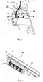
- a luminaire according to an embodiment of the present invention is shown in the overall view in FIG Figure 4 shown. It comprises a light unit 30, which is essentially formed from a profile element that extends between two end faces. The front sides are each covered with a two-piece side wall 1, 2. The light unit is attached to a carrier profile 40 via the side walls 1, 2. The carrier profile 40 is in turn mounted with a busbar 50 according to one embodiment.
- the busbar 50 is mounted on the building side, for example on a room ceiling.
- the support profile 40 is detachably mounted in the busbar, but is fixed with respect to the busbar.
- the light unit 30 is movable relative to the support profile in a pivoting movement about a longitudinal axis which runs parallel to the extension of the support rail and the light unit.
- An example of such a luminaire is also described in the German patent application entitled “Modular Wall Washers and Shelf Washers” by the same applicant.
- the side walls comprise two parts 1 and 2, part 2 being connected to the support rail 40 and part 1 being pushed onto the light unit 30 at the end.
- the Side walls are preferably each formed on two plastic elements.
- the part 2 of the side wall on the support rail side has snap hooks 22 which engage in recesses 11 in the part 1 of the side wall on the light unit side and latch therein.
- the recess 11 has the shape of a segment of a circle, the snap hooks 22 being arranged relative to one another in such a way that they lie at the ends of a shorter but radius-equal segment of a circle.
- the support rail-side part 2 of the side wall also has notches 21 on a cylinder section which cooperate with notches 13 on the light unit-side part 1 of the side wall in order to lock the pivoting movement of the two parts with respect to one another.
- a scale can also be provided on the outside of the side wall 1, 2 which indicate the three locking positions in relation to one another in the embodiment shown.
- FIG. 3 describes the routing of an electrical line 3, which is led from the support rail 40 to the light unit 30 in order to supply the lighting means provided in the light unit with electrical power.
- the electrical line 3 runs in a recess 23 of the part 2 of the side wall.
- the recess 23 continues on the second part 1 of the side wall in a recess 12 which is dimensioned so that the recess 23 opposite the Recess 12 merges into one another in each of the possible angular positions of the two parts 1, 2.
- further guide domes 14 and 15 are provided on part 1 of the side wall, which secure the line routing in the side wall.
- the line 3 is arranged on the inside of the side wall facing in the direction of the light unit 30.
- the line 3 is covered from the outside, which not only enhances the appearance of the lamp, but also provides security in the event of any mechanical contact with the lamp.
- the line could also be arranged in a closed channel or a channel on the outside of the side wall. In the latter case, it would be preferred to close the channel from the outside by a separate cover.
- the line 3 only has to run in one of the two two-piece side walls 1, 2 of the light unit 30.
- the opposite side wall 1, 2 also has the same depressions 23 and cutouts 12 in order to be able to add another line if necessary.
Landscapes
- Engineering & Computer Science (AREA)
- General Engineering & Computer Science (AREA)
- Arrangement Of Elements, Cooling, Sealing, Or The Like Of Lighting Devices (AREA)
- Non-Portable Lighting Devices Or Systems Thereof (AREA)
Abstract
Description
- Die vorliegende Erfindung betrifft verstellbare Leuchten und insbesondere die Leitungsführung und die Verstellmechanik in derartigen Leuchten.
- Im Stand der Technik sind verstellbare Leuchten bekannt, welche ein gebäudeseitig gehaltenes Tragelement sowie eine gegenüber dem Tragelement verstellbare Lichteinheit aufweisen. Da die elektrische Versorgung von der Trageinheit über den Verstellmechanismus gleich welcher Art zu der Lichteinheit geleitet werden muss, ist es im Stand der Technik üblich, die elektrische Verkabelung außenseitig zu verlegen. Dies hat jedoch Nachteile, da das elektrische Kabel von außen leicht beschädigt werden kann und im übrigen das Erscheinungsbild der Leuchte negativ beeinflusst wird.
- Aufgabe der vorliegenden Erfindung ist es, eine Leuchte mit verstellbarer Lichteinheit bereitzustellen, welche einen im Hinblick auf die Funktionalität und das Erscheinungsbild der Leuchte optimierten Verstellmechanismus und eine verbesserte Leitungsführung aufweist.
- Gelöst wird die Aufgabe durch eine Leuchte nach Anspruch 1.
- Eine Besonderheit der Leuchte der vorliegenden Erfindung besteht in der Zweiteiligkeit der Seitenwände, welche sich von dem Trägerprofil zur Lichteinheit erstrecken. Die Seitenwände können insbesondere an einer oder beiden Stirnseiten der Lichteinheit vorgesehen sein und sind mit dem Trägerprofil verbunden. Um einen Verstellmechanismus zwischen der Lichteinheit und dem Trägerprofil zu ermöglichen, sind die Seitenwände zweiteilig ausgeführt und derart miteinander verbunden, dass sie gegeneinander schwenkbar sind. Auf diese Weise lässt sich einerseits sehr einfach der Schwenkmechanismus des Lichtelements gegenüber dem Trägerprofil realisieren. Zum anderen lässt sich dadurch auch die Leitungsführung optimieren, weil die Leitung erfindungsgemäß in einer der Seitenwände integriert ist, wobei die Leitungsführung in jeder der Schwenkpositionen knickfrei von dem einen Teil der Seitenwand, welches an einem Trägerprofil befestigt ist, zu dem anderen Teil der Seitenwand, welches an der Lichteinheit befestigt ist, verlegt ist.
- Gemäß einer Ausführungsform ist die elektrische Leitung in einer Vertiefung eines Teils der Seitenwand geführt und die Vertiefung setzt sich in einer Aussparung in dem zweiten Teil der Seitenwände derart fort, dass in jeder der Schwenkpositionen die Vertiefung und die Aussparung ineinander übergehen. Die Vertiefungen und die Aussparung weisen dazu auch in den jeweils äußeren Winkelstellungen des Bereichs, über welchen Schwenkpositionen eingenommen werden können, eine Überlappung auf, welche der Kabeldicke der hindurchgeführten elektrischen Leitung entspricht. Dadurch liegt das Kabel sicher verlegt in der Seitenwand und wird in keiner der Winkelstellungen beim Schwenken der Lichteinheit gegenüber dem Tragprofil beschädigt.
- Gemäß einer Ausführungsform ist an einem der Teile der Seitenwand wenigstens ein Führungsdom vorgesehen, welcher die Leitung in jeder der Schwenkbewegungen in Position hält. Der eine oder die mehreren Führungsdome dienen der Leitungsführung. Ein Führungsdom ist von Vorteil, weil die Leitung beim Schwenken der Lichteinheit an dem Führungsdom anliegen kann, ohne von den ggf. abgerundeten Wänden des Führungsdoms beschädigt zu werden, auch wenn sich die Leitung gegenüber dem Führungsdom im Rahmen der Schwenkbewegung geringfügig bewegt.
- Gemäß einer Ausführungsform ist eine elektrische Leitung in der Seitenwand auf einer Innenseite davon, die zu einem Innenraum des Trägerprofils und/oder der Lichteinheit weist, verlegt. Das Verlegen der Leitung auf der Innenseite der Seitenwände hat den Vorteil, dass die Leitung nach außen verdeckt ist und ferner zu den Leuchtmitteln in der Lichteinheit bzw. zu einem Anschlussstück in der Tragschiene geführt werden kann. Alternativ kann die elektrische Leitung ohne einen Wanddurchbruch auch in außenseitigen Kanälen der Seitenwand angeordnet sein, wobei diese vorzugsweise abgedeckt sind.
- Gemäß einer Ausführungsform bildet die Seitenwand eine Stirnwand eines Profilelements der Lichteinheit. Die Stirnwand zur Abdeckung des Innenraums der Lichteinheit ist ohnehin notwendig, so dass der Verstellmechanismus, wenn er in der Stirnwand integriert ist, keine zusätzlichen Bauteile erfordert.
- Gemäß einer Ausführungsform weist ein Teil der Seitenwand Schnapphaken auf, die in einer Aussparung des anderen Teils der Seitenwand eingreifen, wobei die Schnapphaken innerhalb der Aussparung beim Verschwenken der beiden Teile entlang gleiten. Die Schnapphaken lassen sich besonders einfach in einem Kunststoffelement, welches die Stirnwand bilden kann, integrieren bzw. einstückig damit herstellen. Dadurch ist das Bauteil besonders einfach herzustellen und weist die volle Funktionalität, die für den Schwenkmechanismus notwendig ist, auf, ohne dass hierzu zusätzliche Bauteile benötigt werden. Alternativ könnte auch eine Schraube oder andere metallische Teil vorgesehen sein, um in einer Aussparung des gegenüberliegenden Teils der Seitenwand einzugreifen.
- Gemäß einer Ausführungsform sind Rasten an einem der beiden Teile der Seitenwand vorgesehen, die in Einkerbungen auf dem zweiten der beiden Teile eingreifen, um die Schwenkposition der beiden Teile in wenigstens zwei, vorzugsweise wenigstens drei Winkelstellungen zu arretieren. Die Rasten können über den Einkerbungen beim Verstellen der Lichteinheit entlanggleiten, so dass die Lichteinheit ohne das Öffnen zusätzlicher Haltemechanismen verstellt werden kann. Die Rasten bilden im Zusammenspiel mit den Vertiefungen eine ausreichende Arretierung, um eine Leuchte mittleren Gewichts auch sicher halten zu können.
- Weitere Vorteile und Merkmale der vorliegenden Erfindung werden aus der nachfolgenden Beschreibung einer bevorzugten Ausführungsform deutlich, die in Verbindung mit den beigefügten Figuren gegeben wird. In den Figuren ist das Folgende dargestellt.
- Figur 1
- zeigt eine Explosionszeichnung einer Seitenwand einer Ausführungsform einer Leuchte von der Innenseite.
- Figur 2
- zeigt eine der
Figur 1 entsprechende Abbildung von der Außenseite der Leuchte. - Figur 3
- zeigt eine Aufsicht auf die Seitenwand gemäß
Figuren 1 und 2 auf die Innenseite mit verlegter elektrischer Leitung. - Figur 4
- zeigt eine perspektivische Ansicht der Gesamtleuchte mit zwei Seitenwänden entsprechend der
Figuren 1 bis 3 . - Eine Leuchte nach einer Ausführungsform der vorliegenden Erfindung ist in der Gesamtansicht in
Figur 4 dargestellt. Sie umfasst eine Lichteinheit 30, welche im Wesentlichen aus einem Profilelement gebildet ist, das sich zwischen zwei Stirnseiten erstreckt. Die Stirnseiten sind mit jeweils mit einer zweistückigen Seitenwand 1,2 abgedeckt. Über die Seitenwände 1,2 ist die Lichteinheit an ein Trägerprofil 40 angebracht. Das Trägerprofil 40 ist wiederum gemäß einer Ausführungsform mit einer Stromschiene 50 montiert. Die Stromschiene 50 ist gebäudeseitig z.B. an einer Raumdecke montiert. Das Tragprofil 40 ist zwar lösbar in der Stromschiene montiert, jedoch gegenüber der Stromschiene festgelegt. Die Lichteinheit 30 ist gegenüber dem Trägerprofil in einer Schwenkbewegung um eine Längsachse, die parallel zur Erstreckung der Tragschiene und der Lichteinheit verläuft, beweglich. Ein Beispiel einer solchen Leuchte ist auch in der deutschen Patentanmeldung mit dem Titel "Modulare Wall- und Shelfwasher" der gleichen Anmelderin beschrieben. - In Bezug auf die
Figuren 1 bis 3 werden im Folgenden die Seitenwände beschrieben, welche die Lichteinheit 30 an dem Trägerprofil 40 halten. In denFiguren 1 bis 3 ist nur jeweils eine Seitenwand dargestellt, wobei zu verstehen ist, dass in der Leuchte gemäßFigur 4 zwei spiegelbildlich identisch ausgebildete Seitenwände vorgesehen sind. - Die Seitenwände umfassen zwei Teile 1 und 2, wobei das Teil 2 mit der Tragschiene 40 verbunden wird und das Teil 1 stirnseitig auf die Lichteinheit 30 aufgesteckt ist. Die Seitenwände sind vorzugsweise jeweils an zwei Kunststoffelementen gebildet.
- Das tragschienenseitige Teil 2 der Seitenwand weist Schnapphaken 22 auf, die in Aussparungen 11 des lichteinheitenseitigen Teils 1 der Seitenwand eingreifen und darin sich verrasten. Die Aussparung 11 weist die Form eines Kreisabschnitts auf, wobei die Schnapphaken 22 so zueinander angeordnet sind, dass sie an den Enden eines kürzeren aber radiusgleichen Kreisabschnitts liegen. Dadurch ist im Verrastzustand die Möglichkeit gegeben, die beiden Teile 1 und 2 der Stirnwand gegeneinander um einen Winkelabschnitt (entlang des Pfeils 4 gemäß
Figur 3 ) zu schwenken, der durch die Differenz der Kreisbogenlängen des Ausschnitts 11 gegenüber den Schnapphaken 22 festgelegt ist. - Das tragschienenseitige Teil 2 der Seitenwand weist ferner auf einem Zylinderabschnitt Rasten 21 auf, die mit Einkerbungen 13 auf dem lichteinheitenseitigen Teil 1 der Seitenwand zusammenwirken, um die Schwenkbewegung der beiden Teile zueinander zu arretieren. Wie in der
Figur 2 dargestellt, kann außenseitig an der Seitenwand 1, 2 auch noch eine Skala vorgesehen sein, welche die in der gezeigten Ausführungsform drei Rastpositionen zueinander anzeigen. - Bezugnehmend auf
Figur 3 wird die Leitungsführung einer elektrischen Leitung 3 beschrieben, die von der Tragschiene 40 zur Lichteinheit 30 geführt ist, um die in der Lichteinheit vorgesehenen Leuchtmittel elektrisch zu versorgen. - Die elektrische Leitung 3 verläuft in einer Vertiefung 23 des Teils 2 der Seitenwand. Die Vertiefung 23 setzt sich auf dem zweiten Teil 1 der Seitenwand in einer Aussparung 12 fort, die so bemessen ist, dass die Vertiefung 23 gegenüber der Aussparung 12 in jeder der möglichen Winkelpositionen der beiden Teile 1, 2 ineinander übergeht. Dadurch ist es möglich, die Leitung 3 knickfrei von dem Teil 2 zum Teil 1 der Seitenwand in jeder der Winkelpositionen zu verlegen. Ferner sind an dem Teil 1 der Seitenwand noch weitere Führungsdome 14 und 15 vorgesehen, welche die Leitungsführung in der Seitenwand sichern. Wie in der
Figur 3 dargestellt, ist die Leitung 3 auf der Innenseite der Seitenwand, die in Richtung zu der Lichteinheit 30 weist, angeordnet. Dadurch ist die Leitung 3 von außen verdeckt, wodurch nicht nur das Erscheinungsbild der Leuchte aufgewertet wird, sondern außerdem eine Sicherheit bei etwaigen mechanischen Berührungen der Leuchte gegeben wird. Allgemein könnte die Leitung jedoch auch in einem geschlossenen Kanal oder einen außenseitigen Kanal der Seitenwand angeordnet sein. In letzterem Fall wäre es bevorzugt, den Kanal nach außen durch eine separate Abdeckung zu verschließen. - Es ist zu verstehen, dass die Leitung 3 nur in einer der beiden zweistückigen Seitenwände 1, 2 der Lichteinheit 30 verlaufen muss. Um eine Flexibilität beim Aufbau der Leuchte zu gewährleiten, ist es jedoch bevorzugt, dass auch die gegenüberliegende Seitenwand 1, 2 die gleichen Vertiefungen 23 und Aussparungen 12 aufweist, um ggf. noch eine weitere Leitung hinzufügen zu können.
-
- 1
- Teil der Seitenwand
- 2
- Teil der Seitenwand
- 3
- Leitung
- 4
- Schwenkrichtung
- 11
- Aussparung für Schnapphaken
- 12
- Aussparung für Leitung
- 13
- Einkerbung
- 14
- Führungsdom
- 15
- Führungsdom
- 21
- Raste
- 22
- Schnapphaken
- 23
- Vertiefung
- 30
- Lichteinheit
- 40
- Tragprofil
- 50
- Stromschiene
Claims (7)
- Leuchte mit einem Trägerprofil (40) und einer Lichteinheit (30), welche Leuchtmittel der Leuchte trägt,
wobei die Lichteinheit (30) wenigstens eine Seitenwand (1, 2) aufweist, die zweistückig ausgebildet ist, wobei ein Stück (1) der Seitenwand mit der Lichteinheit (30) und das zweite Stück (2) der Seitenwand mit dem Trägerprofil (40) verbunden ist,
wobei die zwei Teile der Seitenwand (1, 2) gegeneinander schwenkbar sind, um die Lichteinheit (30) gegenüber dem Trägerprofil (40) zu schwenken,
wobei die elektrische Leitung (3) in jeder der Schwenkpositionen knickfrei in der Seitenwand (1, 2) verlegt ist. - Leuchte nach Anspruch 1, wobei die elektrische Leitung (3) in einer Vertiefung (23) eines Teils (2) der Seitenwand geführt ist, die Vertiefung (23) sich in einer Aussparung (12) in dem zweiten Teil (1) der Seitenwände derart fortsetzt, dass in allen Schwenkpositionen die Vertiefung (23) und die Aussparung (12) ineinander übergehen.
- Leuchte nach einem der vorhergehenden Ansprüche, wobei an einem der Teile (1) der Seitenwand wenigstens ein Führungsdom (14, 15) vorgesehen ist, welcher die Leitung (3) in jeder der Schwenkbewegungen in Position hält.
- Leuchte nach einem der vorhergehenden Ansprüche, wobei eine elektrische Leitung (3) in der Seitenwand (1, 2) auf einer Innenseite davon, die zu einem Innenraum des Trägerprofils (40) und/oder der Lichteinheit (30) weist, verlegt ist.
- Leuchte nach einem der vorhergehenden Ansprüche, wobei die Seitenwand (1, 2) eine Stirnwand der Lichteinheit (30) bildet.
- Leuchte nach einem der vorhergehenden Ansprüche, wobei ein Teil (2) der Seitenwand Schnapphaken (22) aufweist, die in einer Aussparung (11) des anderen Teils (1) der Seitenwand eingreifen, wobei die Schnapphaken (22) innerhalb der Aussparung (11) beim Verschwenken der beiden Teile (1, 2) entlang gleiten.
- Leuchte nach einem der vorhergehenden Ansprüche, wobei Rasten (21) an einem der beiden Teile (2) der Seitenwand vorgesehen sind, die in Einkerbungen (13) auf dem zweiten der beiden Teile (1) eingreifen, um die Schwenkposition der beiden Teile (1, 2) in wenigstens zwei, vorzugsweise wenigstens drei Winkelstellungen zu arretieren.
Applications Claiming Priority (1)
| Application Number | Priority Date | Filing Date | Title |
|---|---|---|---|
| DE102019106680.8A DE102019106680A1 (de) | 2019-03-15 | 2019-03-15 | Stirnseitig Integrierte Leitungsführung und Verstellmechanik |
Publications (2)
| Publication Number | Publication Date |
|---|---|
| EP3708908A1 true EP3708908A1 (de) | 2020-09-16 |
| EP3708908B1 EP3708908B1 (de) | 2022-01-12 |
Family
ID=69784093
Family Applications (1)
| Application Number | Title | Priority Date | Filing Date |
|---|---|---|---|
| EP20161691.9A Active EP3708908B1 (de) | 2019-03-15 | 2020-03-09 | Stirnseitig integrierte leitungsführung und verstellmechanik |
Country Status (2)
| Country | Link |
|---|---|
| EP (1) | EP3708908B1 (de) |
| DE (1) | DE102019106680A1 (de) |
Citations (2)
| Publication number | Priority date | Publication date | Assignee | Title |
|---|---|---|---|---|
| KR20090068070A (ko) * | 2007-12-22 | 2009-06-25 | (주)이상씨앤씨 | 조명설치대 |
| DE202010002018U1 (de) * | 2010-02-05 | 2010-05-06 | Hera Gmbh & Co. Kg | LED Leuchte mit drehbarem Leuchtmittel |
Family Cites Families (3)
| Publication number | Priority date | Publication date | Assignee | Title |
|---|---|---|---|---|
| US5386354A (en) * | 1993-12-17 | 1995-01-31 | Regent Lighting Corporation | Adjustable beam security light |
| DE102010013649A1 (de) * | 2010-03-25 | 2011-09-29 | Alfred Pracht Lichttechnik Gmbh | Leuchte |
| DE202016106607U1 (de) * | 2016-11-28 | 2018-03-01 | Zumtobel Lighting Gmbh | Leuchten-Anordnung mit einer Tragschiene und einer Leuchte |
-
2019
- 2019-03-15 DE DE102019106680.8A patent/DE102019106680A1/de not_active Withdrawn
-
2020
- 2020-03-09 EP EP20161691.9A patent/EP3708908B1/de active Active
Patent Citations (2)
| Publication number | Priority date | Publication date | Assignee | Title |
|---|---|---|---|---|
| KR20090068070A (ko) * | 2007-12-22 | 2009-06-25 | (주)이상씨앤씨 | 조명설치대 |
| DE202010002018U1 (de) * | 2010-02-05 | 2010-05-06 | Hera Gmbh & Co. Kg | LED Leuchte mit drehbarem Leuchtmittel |
Also Published As
| Publication number | Publication date |
|---|---|
| DE102019106680A1 (de) | 2020-09-17 |
| EP3708908B1 (de) | 2022-01-12 |
Similar Documents
| Publication | Publication Date | Title |
|---|---|---|
| EP2131103B1 (de) | Lichtkanalsystem | |
| EP3391470B1 (de) | Leiteranschlussklemme | |
| EP2248503A1 (de) | Medizinische Versorgungseinheit mit verriegelbaren Adaptern | |
| DE9203112U1 (de) | Montageelement für Installationskanäle | |
| EP2248504A1 (de) | Medizinische Versorgungseinheit mit Einbaumodulen | |
| EP0686225B1 (de) | Gehäuse zum aufnehmen von elektrischen antrieben | |
| EP3708908B1 (de) | Stirnseitig integrierte leitungsführung und verstellmechanik | |
| EP3109544B1 (de) | Leuchteneinsatz mit drehriegel | |
| AT526098A2 (de) | Befestigungseinrichtung zum Befestigen einer Leuchtbaugruppe sowie Beleuchtungsanordnung mit mindestens einer derartigen Befestigungseinrichtung | |
| DE202018102643U1 (de) | Adapter für schwere Leuchten | |
| EP3396655A1 (de) | Led-panel | |
| EP0453626B1 (de) | Mit Schlosseinrichtung versehener versenkbarer Schwenkhebelverschluss | |
| DE1440752A1 (de) | Kombinations-Klemmenhalterung und damit ausgestattete Klemmenleiste | |
| EP1873403B1 (de) | Befestigungsvorrichtung mit Schwenkbasis | |
| DE2801852A1 (de) | Installationsmittel fuer die anordnung einer tv-kamera fuer den video-wechselsprechverkehr in einem tableau fuer einen elektrischen tueroeffner | |
| EP0555688B1 (de) | Leuchtstoffleuchte | |
| DE3407701C2 (de) | Schaltschrank mit einer Tür | |
| EP3680551B1 (de) | Leuchtmodul für ein lichtbandsystem | |
| DE102024100353B4 (de) | Leuchte mit verriegelbarem Befestigungsabgriff und Verfahren zur Montage einer Leuchte | |
| DE9416315U1 (de) | Gehäuse für eine Überwachungseinrichtung | |
| DE69614319T2 (de) | Beleuchtungs- und Verdrahtungssystem für Gebäude mit entspechender Kanal- und elektrischer Gerätschaft | |
| DE102018115588A1 (de) | Haltevorrichtung für eine Rangierwabe und Rangierwabe | |
| EP2107298A1 (de) | Langgestreckte Hängeleuchte | |
| DE29503747U1 (de) | Gehäuse | |
| EP2816879B1 (de) | Leitungsanschluss |
Legal Events
| Date | Code | Title | Description |
|---|---|---|---|
| PUAI | Public reference made under article 153(3) epc to a published international application that has entered the european phase |
Free format text: ORIGINAL CODE: 0009012 |
|
| STAA | Information on the status of an ep patent application or granted ep patent |
Free format text: STATUS: THE APPLICATION HAS BEEN PUBLISHED |
|
| AK | Designated contracting states |
Kind code of ref document: A1 Designated state(s): AL AT BE BG CH CY CZ DE DK EE ES FI FR GB GR HR HU IE IS IT LI LT LU LV MC MK MT NL NO PL PT RO RS SE SI SK SM TR |
|
| AX | Request for extension of the european patent |
Extension state: BA ME |
|
| STAA | Information on the status of an ep patent application or granted ep patent |
Free format text: STATUS: REQUEST FOR EXAMINATION WAS MADE |
|
| 17P | Request for examination filed |
Effective date: 20210304 |
|
| RBV | Designated contracting states (corrected) |
Designated state(s): AL AT BE BG CH CY CZ DE DK EE ES FI FR GB GR HR HU IE IS IT LI LT LU LV MC MK MT NL NO PL PT RO RS SE SI SK SM TR |
|
| GRAP | Despatch of communication of intention to grant a patent |
Free format text: ORIGINAL CODE: EPIDOSNIGR1 |
|
| STAA | Information on the status of an ep patent application or granted ep patent |
Free format text: STATUS: GRANT OF PATENT IS INTENDED |
|
| RIC1 | Information provided on ipc code assigned before grant |
Ipc: F21V 21/30 20060101AFI20210628BHEP Ipc: F21V 27/02 20060101ALI20210628BHEP Ipc: F21V 15/015 20060101ALI20210628BHEP Ipc: F21V 21/35 20060101ALI20210628BHEP Ipc: F21S 8/00 20060101ALI20210628BHEP Ipc: F21V 7/00 20060101ALN20210628BHEP Ipc: F21V 7/04 20060101ALN20210628BHEP Ipc: F21V 15/01 20060101ALN20210628BHEP Ipc: F21V 17/16 20060101ALN20210628BHEP Ipc: F21V 23/00 20150101ALN20210628BHEP Ipc: F21W 131/405 20060101ALN20210628BHEP Ipc: F21Y 115/10 20160101ALN20210628BHEP Ipc: F21Y 103/10 20160101ALN20210628BHEP |
|
| INTG | Intention to grant announced |
Effective date: 20210730 |
|
| GRAS | Grant fee paid |
Free format text: ORIGINAL CODE: EPIDOSNIGR3 |
|
| GRAA | (expected) grant |
Free format text: ORIGINAL CODE: 0009210 |
|
| STAA | Information on the status of an ep patent application or granted ep patent |
Free format text: STATUS: THE PATENT HAS BEEN GRANTED |
|
| AK | Designated contracting states |
Kind code of ref document: B1 Designated state(s): AL AT BE BG CH CY CZ DE DK EE ES FI FR GB GR HR HU IE IS IT LI LT LU LV MC MK MT NL NO PL PT RO RS SE SI SK SM TR |
|
| REG | Reference to a national code |
Ref country code: GB Ref legal event code: FG4D Free format text: NOT ENGLISH |
|
| REG | Reference to a national code |
Ref country code: CH Ref legal event code: EP |
|
| REG | Reference to a national code |
Ref country code: DE Ref legal event code: R096 Ref document number: 502020000539 Country of ref document: DE |
|
| REG | Reference to a national code |
Ref country code: IE Ref legal event code: FG4D Free format text: LANGUAGE OF EP DOCUMENT: GERMAN |
|
| REG | Reference to a national code |
Ref country code: AT Ref legal event code: REF Ref document number: 1462624 Country of ref document: AT Kind code of ref document: T Effective date: 20220215 |
|
| REG | Reference to a national code |
Ref country code: LT Ref legal event code: MG9D |
|
| REG | Reference to a national code |
Ref country code: NL Ref legal event code: MP Effective date: 20220112 |
|
| PG25 | Lapsed in a contracting state [announced via postgrant information from national office to epo] |
Ref country code: NL Free format text: LAPSE BECAUSE OF FAILURE TO SUBMIT A TRANSLATION OF THE DESCRIPTION OR TO PAY THE FEE WITHIN THE PRESCRIBED TIME-LIMIT Effective date: 20220112 |
|
| PG25 | Lapsed in a contracting state [announced via postgrant information from national office to epo] |
Ref country code: SE Free format text: LAPSE BECAUSE OF FAILURE TO SUBMIT A TRANSLATION OF THE DESCRIPTION OR TO PAY THE FEE WITHIN THE PRESCRIBED TIME-LIMIT Effective date: 20220112 Ref country code: RS Free format text: LAPSE BECAUSE OF FAILURE TO SUBMIT A TRANSLATION OF THE DESCRIPTION OR TO PAY THE FEE WITHIN THE PRESCRIBED TIME-LIMIT Effective date: 20220112 Ref country code: PT Free format text: LAPSE BECAUSE OF FAILURE TO SUBMIT A TRANSLATION OF THE DESCRIPTION OR TO PAY THE FEE WITHIN THE PRESCRIBED TIME-LIMIT Effective date: 20220512 Ref country code: NO Free format text: LAPSE BECAUSE OF FAILURE TO SUBMIT A TRANSLATION OF THE DESCRIPTION OR TO PAY THE FEE WITHIN THE PRESCRIBED TIME-LIMIT Effective date: 20220412 Ref country code: LT Free format text: LAPSE BECAUSE OF FAILURE TO SUBMIT A TRANSLATION OF THE DESCRIPTION OR TO PAY THE FEE WITHIN THE PRESCRIBED TIME-LIMIT Effective date: 20220112 Ref country code: HR Free format text: LAPSE BECAUSE OF FAILURE TO SUBMIT A TRANSLATION OF THE DESCRIPTION OR TO PAY THE FEE WITHIN THE PRESCRIBED TIME-LIMIT Effective date: 20220112 Ref country code: ES Free format text: LAPSE BECAUSE OF FAILURE TO SUBMIT A TRANSLATION OF THE DESCRIPTION OR TO PAY THE FEE WITHIN THE PRESCRIBED TIME-LIMIT Effective date: 20220112 Ref country code: BG Free format text: LAPSE BECAUSE OF FAILURE TO SUBMIT A TRANSLATION OF THE DESCRIPTION OR TO PAY THE FEE WITHIN THE PRESCRIBED TIME-LIMIT Effective date: 20220412 |
|
| PG25 | Lapsed in a contracting state [announced via postgrant information from national office to epo] |
Ref country code: PL Free format text: LAPSE BECAUSE OF FAILURE TO SUBMIT A TRANSLATION OF THE DESCRIPTION OR TO PAY THE FEE WITHIN THE PRESCRIBED TIME-LIMIT Effective date: 20220112 Ref country code: LV Free format text: LAPSE BECAUSE OF FAILURE TO SUBMIT A TRANSLATION OF THE DESCRIPTION OR TO PAY THE FEE WITHIN THE PRESCRIBED TIME-LIMIT Effective date: 20220112 Ref country code: GR Free format text: LAPSE BECAUSE OF FAILURE TO SUBMIT A TRANSLATION OF THE DESCRIPTION OR TO PAY THE FEE WITHIN THE PRESCRIBED TIME-LIMIT Effective date: 20220413 Ref country code: FI Free format text: LAPSE BECAUSE OF FAILURE TO SUBMIT A TRANSLATION OF THE DESCRIPTION OR TO PAY THE FEE WITHIN THE PRESCRIBED TIME-LIMIT Effective date: 20220112 |
|
| PG25 | Lapsed in a contracting state [announced via postgrant information from national office to epo] |
Ref country code: IS Free format text: LAPSE BECAUSE OF FAILURE TO SUBMIT A TRANSLATION OF THE DESCRIPTION OR TO PAY THE FEE WITHIN THE PRESCRIBED TIME-LIMIT Effective date: 20220512 |
|
| REG | Reference to a national code |
Ref country code: DE Ref legal event code: R097 Ref document number: 502020000539 Country of ref document: DE |
|
| PG25 | Lapsed in a contracting state [announced via postgrant information from national office to epo] |
Ref country code: SM Free format text: LAPSE BECAUSE OF FAILURE TO SUBMIT A TRANSLATION OF THE DESCRIPTION OR TO PAY THE FEE WITHIN THE PRESCRIBED TIME-LIMIT Effective date: 20220112 Ref country code: SK Free format text: LAPSE BECAUSE OF FAILURE TO SUBMIT A TRANSLATION OF THE DESCRIPTION OR TO PAY THE FEE WITHIN THE PRESCRIBED TIME-LIMIT Effective date: 20220112 Ref country code: RO Free format text: LAPSE BECAUSE OF FAILURE TO SUBMIT A TRANSLATION OF THE DESCRIPTION OR TO PAY THE FEE WITHIN THE PRESCRIBED TIME-LIMIT Effective date: 20220112 Ref country code: MC Free format text: LAPSE BECAUSE OF FAILURE TO SUBMIT A TRANSLATION OF THE DESCRIPTION OR TO PAY THE FEE WITHIN THE PRESCRIBED TIME-LIMIT Effective date: 20220112 Ref country code: EE Free format text: LAPSE BECAUSE OF FAILURE TO SUBMIT A TRANSLATION OF THE DESCRIPTION OR TO PAY THE FEE WITHIN THE PRESCRIBED TIME-LIMIT Effective date: 20220112 Ref country code: DK Free format text: LAPSE BECAUSE OF FAILURE TO SUBMIT A TRANSLATION OF THE DESCRIPTION OR TO PAY THE FEE WITHIN THE PRESCRIBED TIME-LIMIT Effective date: 20220112 Ref country code: CZ Free format text: LAPSE BECAUSE OF FAILURE TO SUBMIT A TRANSLATION OF THE DESCRIPTION OR TO PAY THE FEE WITHIN THE PRESCRIBED TIME-LIMIT Effective date: 20220112 |
|
| PLBE | No opposition filed within time limit |
Free format text: ORIGINAL CODE: 0009261 |
|
| STAA | Information on the status of an ep patent application or granted ep patent |
Free format text: STATUS: NO OPPOSITION FILED WITHIN TIME LIMIT |
|
| PG25 | Lapsed in a contracting state [announced via postgrant information from national office to epo] |
Ref country code: AL Free format text: LAPSE BECAUSE OF FAILURE TO SUBMIT A TRANSLATION OF THE DESCRIPTION OR TO PAY THE FEE WITHIN THE PRESCRIBED TIME-LIMIT Effective date: 20220112 |
|
| REG | Reference to a national code |
Ref country code: BE Ref legal event code: MM Effective date: 20220331 |
|
| 26N | No opposition filed |
Effective date: 20221013 |
|
| PG25 | Lapsed in a contracting state [announced via postgrant information from national office to epo] |
Ref country code: LU Free format text: LAPSE BECAUSE OF NON-PAYMENT OF DUE FEES Effective date: 20220309 Ref country code: IE Free format text: LAPSE BECAUSE OF NON-PAYMENT OF DUE FEES Effective date: 20220309 |
|
| PG25 | Lapsed in a contracting state [announced via postgrant information from national office to epo] |
Ref country code: SI Free format text: LAPSE BECAUSE OF FAILURE TO SUBMIT A TRANSLATION OF THE DESCRIPTION OR TO PAY THE FEE WITHIN THE PRESCRIBED TIME-LIMIT Effective date: 20220112 Ref country code: BE Free format text: LAPSE BECAUSE OF NON-PAYMENT OF DUE FEES Effective date: 20220331 |
|
| PG25 | Lapsed in a contracting state [announced via postgrant information from national office to epo] |
Ref country code: IT Free format text: LAPSE BECAUSE OF FAILURE TO SUBMIT A TRANSLATION OF THE DESCRIPTION OR TO PAY THE FEE WITHIN THE PRESCRIBED TIME-LIMIT Effective date: 20220112 |
|
| PG25 | Lapsed in a contracting state [announced via postgrant information from national office to epo] |
Ref country code: MK Free format text: LAPSE BECAUSE OF FAILURE TO SUBMIT A TRANSLATION OF THE DESCRIPTION OR TO PAY THE FEE WITHIN THE PRESCRIBED TIME-LIMIT Effective date: 20220112 Ref country code: CY Free format text: LAPSE BECAUSE OF FAILURE TO SUBMIT A TRANSLATION OF THE DESCRIPTION OR TO PAY THE FEE WITHIN THE PRESCRIBED TIME-LIMIT Effective date: 20220112 |
|
| PG25 | Lapsed in a contracting state [announced via postgrant information from national office to epo] |
Ref country code: HU Free format text: LAPSE BECAUSE OF FAILURE TO SUBMIT A TRANSLATION OF THE DESCRIPTION OR TO PAY THE FEE WITHIN THE PRESCRIBED TIME-LIMIT; INVALID AB INITIO Effective date: 20200309 |
|
| PG25 | Lapsed in a contracting state [announced via postgrant information from national office to epo] |
Ref country code: MT Free format text: LAPSE BECAUSE OF FAILURE TO SUBMIT A TRANSLATION OF THE DESCRIPTION OR TO PAY THE FEE WITHIN THE PRESCRIBED TIME-LIMIT Effective date: 20220112 |
|
| PGFP | Annual fee paid to national office [announced via postgrant information from national office to epo] |
Ref country code: CH Payment date: 20250401 Year of fee payment: 6 |
|
| PG25 | Lapsed in a contracting state [announced via postgrant information from national office to epo] |
Ref country code: TR Free format text: LAPSE BECAUSE OF FAILURE TO SUBMIT A TRANSLATION OF THE DESCRIPTION OR TO PAY THE FEE WITHIN THE PRESCRIBED TIME-LIMIT Effective date: 20220112 |
|
| REG | Reference to a national code |
Ref country code: CH Ref legal event code: U11 Free format text: ST27 STATUS EVENT CODE: U-0-0-U10-U11 (AS PROVIDED BY THE NATIONAL OFFICE) Effective date: 20260401 |
|
| PGFP | Annual fee paid to national office [announced via postgrant information from national office to epo] |
Ref country code: GB Payment date: 20260317 Year of fee payment: 7 |
|
| PGFP | Annual fee paid to national office [announced via postgrant information from national office to epo] |
Ref country code: DE Payment date: 20260320 Year of fee payment: 7 |
|
| PGFP | Annual fee paid to national office [announced via postgrant information from national office to epo] |
Ref country code: AT Payment date: 20260319 Year of fee payment: 7 |
|
| PGFP | Annual fee paid to national office [announced via postgrant information from national office to epo] |
Ref country code: FR Payment date: 20260325 Year of fee payment: 7 |