EP3708482B1 - Ruder für wasserfahrzeuge mit einer lagerspielmessvorrichtung, verfahren zur messung eines lagerspiels in einem ruder und lagerspielmessvorrichtung für ein ruder - Google Patents
Ruder für wasserfahrzeuge mit einer lagerspielmessvorrichtung, verfahren zur messung eines lagerspiels in einem ruder und lagerspielmessvorrichtung für ein ruder Download PDFInfo
- Publication number
- EP3708482B1 EP3708482B1 EP20160036.8A EP20160036A EP3708482B1 EP 3708482 B1 EP3708482 B1 EP 3708482B1 EP 20160036 A EP20160036 A EP 20160036A EP 3708482 B1 EP3708482 B1 EP 3708482B1
- Authority
- EP
- European Patent Office
- Prior art keywords
- rudder
- sensor
- bearing
- abrasion
- measurement
- Prior art date
- Legal status (The legal status is an assumption and is not a legal conclusion. Google has not performed a legal analysis and makes no representation as to the accuracy of the status listed.)
- Active
Links
Images


Classifications
-
- F—MECHANICAL ENGINEERING; LIGHTING; HEATING; WEAPONS; BLASTING
- F16—ENGINEERING ELEMENTS AND UNITS; GENERAL MEASURES FOR PRODUCING AND MAINTAINING EFFECTIVE FUNCTIONING OF MACHINES OR INSTALLATIONS; THERMAL INSULATION IN GENERAL
- F16C—SHAFTS; FLEXIBLE SHAFTS; ELEMENTS OR CRANKSHAFT MECHANISMS; ROTARY BODIES OTHER THAN GEARING ELEMENTS; BEARINGS
- F16C17/00—Sliding-contact bearings for exclusively rotary movement
- F16C17/02—Sliding-contact bearings for exclusively rotary movement for radial load only
-
- B—PERFORMING OPERATIONS; TRANSPORTING
- B63—SHIPS OR OTHER WATERBORNE VESSELS; RELATED EQUIPMENT
- B63H—MARINE PROPULSION OR STEERING
- B63H25/00—Steering; Slowing-down otherwise than by use of propulsive elements; Dynamic anchoring, i.e. positioning vessels by means of main or auxiliary propulsive elements
- B63H25/06—Steering by rudders
- B63H25/38—Rudders
-
- B—PERFORMING OPERATIONS; TRANSPORTING
- B63—SHIPS OR OTHER WATERBORNE VESSELS; RELATED EQUIPMENT
- B63H—MARINE PROPULSION OR STEERING
- B63H25/00—Steering; Slowing-down otherwise than by use of propulsive elements; Dynamic anchoring, i.e. positioning vessels by means of main or auxiliary propulsive elements
- B63H25/52—Parts for steering not otherwise provided for
-
- F—MECHANICAL ENGINEERING; LIGHTING; HEATING; WEAPONS; BLASTING
- F16—ENGINEERING ELEMENTS AND UNITS; GENERAL MEASURES FOR PRODUCING AND MAINTAINING EFFECTIVE FUNCTIONING OF MACHINES OR INSTALLATIONS; THERMAL INSULATION IN GENERAL
- F16C—SHAFTS; FLEXIBLE SHAFTS; ELEMENTS OR CRANKSHAFT MECHANISMS; ROTARY BODIES OTHER THAN GEARING ELEMENTS; BEARINGS
- F16C17/00—Sliding-contact bearings for exclusively rotary movement
- F16C17/12—Sliding-contact bearings for exclusively rotary movement characterised by features not related to the direction of the load
- F16C17/24—Sliding-contact bearings for exclusively rotary movement characterised by features not related to the direction of the load with devices affected by abnormal or undesired positions, e.g. for preventing overheating, for safety
- F16C17/246—Sliding-contact bearings for exclusively rotary movement characterised by features not related to the direction of the load with devices affected by abnormal or undesired positions, e.g. for preventing overheating, for safety related to wear, e.g. sensors for measuring wear
-
- G—PHYSICS
- G01—MEASURING; TESTING
- G01B—MEASURING LENGTH, THICKNESS OR SIMILAR LINEAR DIMENSIONS; MEASURING ANGLES; MEASURING AREAS; MEASURING IRREGULARITIES OF SURFACES OR CONTOURS
- G01B17/00—Measuring arrangements characterised by the use of infrasonic, sonic or ultrasonic vibrations
-
- G—PHYSICS
- G01—MEASURING; TESTING
- G01B—MEASURING LENGTH, THICKNESS OR SIMILAR LINEAR DIMENSIONS; MEASURING ANGLES; MEASURING AREAS; MEASURING IRREGULARITIES OF SURFACES OR CONTOURS
- G01B17/00—Measuring arrangements characterised by the use of infrasonic, sonic or ultrasonic vibrations
- G01B17/02—Measuring arrangements characterised by the use of infrasonic, sonic or ultrasonic vibrations for measuring thickness
-
- G—PHYSICS
- G01—MEASURING; TESTING
- G01B—MEASURING LENGTH, THICKNESS OR SIMILAR LINEAR DIMENSIONS; MEASURING ANGLES; MEASURING AREAS; MEASURING IRREGULARITIES OF SURFACES OR CONTOURS
- G01B21/00—Measuring arrangements or details thereof, where the measuring technique is not covered by the other groups of this subclass, unspecified or not relevant
- G01B21/16—Measuring arrangements or details thereof, where the measuring technique is not covered by the other groups of this subclass, unspecified or not relevant for measuring distance of clearance between spaced objects
-
- G—PHYSICS
- G01—MEASURING; TESTING
- G01B—MEASURING LENGTH, THICKNESS OR SIMILAR LINEAR DIMENSIONS; MEASURING ANGLES; MEASURING AREAS; MEASURING IRREGULARITIES OF SURFACES OR CONTOURS
- G01B5/00—Measuring arrangements characterised by the use of mechanical techniques
- G01B5/14—Measuring arrangements characterised by the use of mechanical techniques for measuring distance or clearance between spaced objects or spaced apertures
- G01B5/146—Measuring arrangements characterised by the use of mechanical techniques for measuring distance or clearance between spaced objects or spaced apertures measuring play on bearings
-
- G—PHYSICS
- G01—MEASURING; TESTING
- G01B—MEASURING LENGTH, THICKNESS OR SIMILAR LINEAR DIMENSIONS; MEASURING ANGLES; MEASURING AREAS; MEASURING IRREGULARITIES OF SURFACES OR CONTOURS
- G01B7/00—Measuring arrangements characterised by the use of electric or magnetic techniques
- G01B7/02—Measuring arrangements characterised by the use of electric or magnetic techniques for measuring length, width or thickness
- G01B7/06—Measuring arrangements characterised by the use of electric or magnetic techniques for measuring length, width or thickness for measuring thickness
- G01B7/10—Measuring arrangements characterised by the use of electric or magnetic techniques for measuring length, width or thickness for measuring thickness using magnetic means, e.g. by measuring change of reluctance
-
- G—PHYSICS
- G01—MEASURING; TESTING
- G01B—MEASURING LENGTH, THICKNESS OR SIMILAR LINEAR DIMENSIONS; MEASURING ANGLES; MEASURING AREAS; MEASURING IRREGULARITIES OF SURFACES OR CONTOURS
- G01B7/00—Measuring arrangements characterised by the use of electric or magnetic techniques
- G01B7/14—Measuring arrangements characterised by the use of electric or magnetic techniques for measuring distance or clearance between spaced objects or spaced apertures
- G01B7/144—Measuring play on bearings
-
- G—PHYSICS
- G01—MEASURING; TESTING
- G01M—TESTING STATIC OR DYNAMIC BALANCE OF MACHINES OR STRUCTURES; TESTING OF STRUCTURES OR APPARATUS, NOT OTHERWISE PROVIDED FOR
- G01M13/00—Testing of machine parts
- G01M13/04—Bearings
-
- F—MECHANICAL ENGINEERING; LIGHTING; HEATING; WEAPONS; BLASTING
- F16—ENGINEERING ELEMENTS AND UNITS; GENERAL MEASURES FOR PRODUCING AND MAINTAINING EFFECTIVE FUNCTIONING OF MACHINES OR INSTALLATIONS; THERMAL INSULATION IN GENERAL
- F16C—SHAFTS; FLEXIBLE SHAFTS; ELEMENTS OR CRANKSHAFT MECHANISMS; ROTARY BODIES OTHER THAN GEARING ELEMENTS; BEARINGS
- F16C2233/00—Monitoring condition, e.g. temperature, load, vibration
-
- F—MECHANICAL ENGINEERING; LIGHTING; HEATING; WEAPONS; BLASTING
- F16—ENGINEERING ELEMENTS AND UNITS; GENERAL MEASURES FOR PRODUCING AND MAINTAINING EFFECTIVE FUNCTIONING OF MACHINES OR INSTALLATIONS; THERMAL INSULATION IN GENERAL
- F16C—SHAFTS; FLEXIBLE SHAFTS; ELEMENTS OR CRANKSHAFT MECHANISMS; ROTARY BODIES OTHER THAN GEARING ELEMENTS; BEARINGS
- F16C2326/00—Articles relating to transporting
- F16C2326/30—Ships, e.g. propelling shafts and bearings therefor
Definitions
- the present invention relates to a rudder for watercraft, in particular for ships, comprising a rudder stock arranged in a trunk, a rudder blade connected to the rudder stock, a bearing bush arranged between trunk and rudder stock, and a bearing play measuring device. Furthermore, the present invention relates to a method for measuring a bearing play in a rudder and a system consisting of a rudder trunk tube and a bearing play measuring device for a rudder.
- Rudders for watercraft, in particular for ships, include a rudder blade attached to a rudder post.
- the rudder stock is usually guided in a trunk pipe arranged at the stern of the ship so that it can rotate about the rudder stock axis.
- At least one bearing bush is provided for mounting the rudder stock in the trunk tube, which is preferably arranged in the region of the lower end of the trunk tube.
- the bearing bush Due to the large rudder forces that occur during operation, the bearing bush is subject to heavy wear, which can lead to damage to the rudder or even failure of the entire rudder system. For this reason, the bearing play caused by wear, i.e. the play of the rudder in the bearing bush or in the rudder trunk, must be measured regularly. In the prior art, the bearing clearance measurement is usually carried out manually by qualified divers under water on the port or starboard side of the rudder.
- the rudder includes a bearing for supporting a rudder blade or a rudder stock on the ship's hull.
- the bearing has an inner bearing portion and an outer bearing portion slidably abutting the inner bearing portion.
- a wear pin is provided which is arranged on the outer bearing portion or on the inner bearing portion and further abuts slidably on the other of the inner bearing portion and the outer bearing portion.
- the KR 2012-0118117 A discloses a method for inspecting a gap between a rudder stock and a tack bearing of a ship.
- a measuring device comprises a holder and a measuring pin which is resiliently mounted in the holder.
- the present invention is based on the object of providing a rudder for watercraft, in particular for ships, with a low-maintenance bearing play measuring device with which a cost-efficient and preferably automatic measurement of a bearing play is made possible, with the measurement directly providing the measured values relevant for a quantification of the bearing play . Furthermore, it is the object of the present invention to provide a method for measuring a bearing play in a rudder and a bearing play measuring device for a rudder, with which the aforementioned advantages are achieved.
- a rudder for watercraft in particular for ships, comprising a rudder stock arranged in a trunk, a rudder blade connected to the rudder stock and a bearing bush arranged between the trunk and rudder stock, with a bearing play measuring device also being provided which at least a sensor for includes wear-free measurement of a bearing clearance, wherein the at least one sensor is arranged without contact and at a distance from the rudder stock, and/or wherein the at least one sensor is an eddy current sensor or an ultrasonic sensor.
- the rudder for watercraft is designed in particular for large ships such as passenger ships, container ships, tankers, bulkers or ferries.
- the rudder blade of the rudder is usually attached to a rudder stock of the rudder.
- the rudder stock is rotatably connected to the watercraft by means of a rudder system arranged in the hull of the watercraft.
- the rudder post can be guided in a trunk pipe protruding downwards from the hull of the watercraft.
- the rudder stock is rotatably mounted in the trunk tube with bearings, in particular with neck bearings.
- the bearing has at least one bearing bush, which is arranged either on the rudder stock and/or on the trunk pipe.
- the bearing bush can be arranged on the inside and non-rotatably in the coker tube.
- the rudder stock or another bearing bushing fastened to the rudder stock is in sliding contact with the bearing bushing arranged in the trunk pipe.
- a bearing bushing can also be arranged on an outside of the coker tube.
- the rudder is mounted on the outside of the bearing bush on the trunk via the rudder blade, and a further bearing bush can be provided on the rudder blade, which is in sliding contact with the bearing bush arranged on the outside of the trunk.
- the present invention is suitable for all of the above configurations and arrangements of the bearings or the bearing bushes.
- a further solution to the object on which the invention is based is therefore also the provision of a rudder for watercraft, in particular for ships, comprising a rudder stock arranged in a trunk pipe, a rudder blade connected to the rudder stock and a bearing bushing arranged between trunk pipe and rudder blade, as well as a bearing play measuring device, wherein the bearing play measuring device comprises at least one sensor for the abrasion-free measurement of a bearing play, the at least one sensor being free of contact and spaced apart from the rudder stock is arranged, and/or wherein the at least one sensor is an eddy current sensor or an ultrasonic sensor.
- an abrasion-free measurement of a bearing play is understood to mean a measurement in which the sensor is essentially not subject to any abrasion.
- the terms "wear-free” and “wear” can also be used synonymously with the terms “abrasion-free” and “abrasion”. Since the sensor is not subject to abrasion or wear, the bearing clearance measuring device is particularly maintenance-free.
- a bearing play is understood to mean a play, in particular a radial play, of the rudder stock in the trunk pipe or in the bearing bush.
- the rudder forces acting on the rudder during operation can lead to wear of the bearing bush.
- This wear of the bearing bush means that the rudder stock in the trunk pipe or the rudder blade on the trunk pipe can deflect in a radial direction in addition to rotating about the axis of the rudder stock, which can result in damage to the trunk pipe, the rudder, the rudder stock or the rudder system.
- the bearing play measuring device with a sensor for wear-free measurement of a bearing play can be used to determine in good time when there is bearing play, so that measures can then be taken to prevent damage. For example, the bearing or the bearing bush can be renewed.
- the bearing play measurement using a sensor for abrasion-free measurement of a bearing play means that manual measurements carried out under water by qualified divers can largely be dispensed with. Since manual measurements cannot be carried out at all times, the bearing play measurement using a sensor for wear-free measurement of a bearing play enables a continuous and therefore particularly timely measurement of the bearing play.
- the at least one sensor for abrasion-free measurement of a bearing play is a sensor for abrasion-free measurement of a distance between the sensor and the rudder post and/or for abrasion-free measurement of a wall thickness of the bearing bush.
- the bearing play measuring device By measuring a distance between the sensor and the rudder stock and/or measuring a wall thickness of the bearing bush, the bearing play measuring device directly determines those measured values that are relevant for quantifying the bearing play.
- the bearing clearance is determined using auxiliary measured values.
- a well-known auxiliary measured value is the abrasion of a sensor for measuring the bearing clearance, from which the bearing clearance is then derived.
- the at least one sensor is arranged without contact and at a distance from the rudder stock.
- the at least one sensor is therefore not arranged in physical contact with the rudder stock, which is rotatably guided in the trunk pipe. Since there is no physical contact between the sensor and the rudder stock, the sensor is also not subject to abrasion.
- the sensor is arranged in particular at a distance of at least 10 mm, preferably at a distance of at least 30 mm, more preferably at a distance of at least 40 mm, particularly preferably at a distance of at least 50 mm from the rudder stock.
- Bearing bushes for rudders for watercraft usually have a wall thickness between 10 mm and 50 mm. Accordingly, an advantage of locating the sensor spaced from the rudder stock is that the bushing can be located between the sensor and the rudder stock.
- the sensor is particularly preferably arranged in contact with the outside of the bearing bush.
- the bearing bushing is also particularly advantageously arranged in a fixed manner in or on the trunk pipe, which means that the bearing bushing does not rotate with the rudder stock or the rudder.
- the at least one sensor is arranged on the outside of the, in particular fixed, bearing bush the sensor can be in contact with the bearing bush without causing the sensor to wear.
- the at least one sensor is arranged above or below the bearing bush, viewed in an axial direction of the rudder stock.
- the at least one sensor is arranged above or below the bearing bush, a completely contact-free measurement of the bearing play is possible.
- the sensor is in contact neither with the rudder stock nor with the bearing bush.
- the non-contact measurement does not rule out the possibility of sea water, contact agents or lubricants such as grease being arranged between the sensor and the bearing bush or between the sensor and the rudder stock.
- At least two, preferably at least three, particularly preferably at least four sensors are provided, with the sensors being arranged, in particular at regular angular intervals, over a circumference of the trunk pipe and/or the bearing bush.
- the sensors are preferably arranged over the circumference of the coker tube. If three sensors are provided, the angular distance between the sensors is preferably 120°. With four sensors, the angular spacing is preferably 90°.
- the at least one sensor in particular at least one of the sensors, is arranged in a rear-side area of the, in particular fixed, coker pipe.
- the trunk pipe is usually fixed to the hull of the watercraft and is not rotatably mounted. Since the rudder forces on the rudder act particularly strongly against the direction of travel backwards in the aft direction during normal forward travel of the watercraft, the greatest abrasion of the bearing bushing is to be expected in the aft-side area of the bearing bushing. For this reason, it is particularly advantageous if at least one of the sensors is arranged in the aft area, in particular exactly astern. If further sensors are provided, for example four sensors, two sensors are arranged exactly athwartships, i.e. at 90° to the longitudinal axis of the watercraft, while a fourth sensor is arranged exactly on the longitudinal axis in the forward direction or in the direction of the bow.
- a sensor receptacle can thus be provided on the coker tube.
- the sensor receptacle can be, for example, a drilled hole, preferably with an internal thread, placed in the coker tube after the production of the coker tube.
- the at least one sensor is then expediently introduced into the sensor receptacle from the outside of the coker tube and fastened there. To fix the sensor, it can be screwed directly into the drill hole.
- other fastening means such as adhesives, resins or other screw connections can also be provided.
- the at least one sensor is an eddy current sensor or an ultrasonic sensor.
- the senor is an eddy current sensor.
- An inductive measurement of the bearing play can be made possible with an eddy current sensor.
- the effect used by an eddy current sensor is based on the extraction of energy from an oscillating circuit.
- the eddy current sensor therefore preferably has a coil which can be supplied with alternating current. When the coil is fed with alternating current, a magnetic field forms in the coil. According to Faraday's law of induction, an eddy current then develops in the rudder stock, which is located in the vicinity of the eddy current sensor and is usually made of stainless steel, which in turn forms a magnetic field. This induced magnetic field opposes the field of the coil, resulting in a change in coil impedance.
- the impedance can be measured as a change in the amplitude and phase position of the sensor coil and can be accessed as a measurable variable.
- the distance between the eddy current sensor and the rudder stock can be deduced from the change in the amplitude and the phase position.
- the at least one sensor is designed as an eddy current sensor
- the sensor is arranged above or below the bearing bush, viewed in an axial direction of the rudder stock. This enables contact-free measurement of the distance from the sensor to the rudder stock.
- the bearing bushing is advantageously not arranged between the eddy current sensor and the rudder post, so that the material of the bearing bushing cannot adversely affect the distance measurement.
- the eddy current sensor is preferably arranged at a minimum distance of at least 5 mm, more preferably at least 10 mm, very particularly preferably at least 20 mm, above or below the bearing bush.
- any materials located between the eddy current sensor and the rudder stock such as water, air, lubricants, in particular fats, do not adversely affect the distance measurement.
- the measurement of the distance between the rudder post and the sensor, in particular the eddy current sensor, is a wear-free and non-contact measurement of the bearing play.
- At least one of the sensors can also be designed as an ultrasonic sensor.
- the ultrasonic sensor is preferably arranged in direct contact with the bearing bush, which is more preferably stationary.
- the wall thickness of the bearing bush in the area of the ultrasonic sensor can be determined directly by transmitting and receiving ultrasonic waves.
- a contact-free measurement is also possible with an ultrasonic sensor.
- the ultrasonic sensor is not in direct physical contact with the bearing bush and/or the rudder stock.
- the ultrasonic sensor can also be arranged above or below the bearing bushing on the trunk pipe, so that the distance from the rudder stock is determined by means of the ultrasonic waves emitted and received by the ultrasonic sensor. The ultrasonic waves are reflected on the rudder stock.
- a non-contact measurement with ultrasonic sensors is particularly preferred when the wall thickness of the bearing bush is to be determined, but the bearing bush is not attached to the trunk but to the rudder stock and thus rotates in the trunk with the rudder stock.
- the provision of a contact means improves the measurement by the ultrasonic sensor.
- a non-stationary bearing bush i.e. a bearing bush which rotates with the rudder stock
- direct physical contact between the ultrasonic sensor and the bearing bush and/or the rudder stock can be avoided by the contact means arranged between the ultrasonic sensor and the bearing bush, so that it is still possible to measure the distance between the sensor and the rudder stock or the wall thickness of the bearing bush without abrasion.
- the at least one sensor is arranged on a holder, the holder being fastened to the liner, in particular to an end face of the liner.
- a retrofit solution for existing rudders is provided by attaching the at least one sensor to a holder.
- an already existing rudder can be retrofitted with a holder having at least one sensor, in order to also enable a wear-free measurement of the bearing play in the existing rudder.
- the holder is preferably a milled component.
- the holder can thus be manufactured using means and methods known from the prior art and is particularly inexpensive to produce.
- the holder can either be inserted into the interior of the coker tube and fixed there, for example above or below the bearing bush.
- the holder it is also possible for the holder to be placed on an end face of the lower end of the trunk pipe protruding from the hull of the watercraft, so that the sensor attached to the holder measures the distance from the area of the rudder stock protruding from the trunk pipe to the sensor.
- the holder is preferably designed in the form of a ring.
- the holder comprises at least one ring segment.
- the at least one ring segment preferably covers an angular range of at least 90°, more preferably at least 120°, even more preferably at least 180°, very particularly 360°.
- the at least one ring segment is, for example, a quarter ring, a third ring, a half ring or a full ring.
- the holder can comprise more than one ring segment. If the multiple ring segments are arranged in one plane, it is preferably provided that the multiple ring segments together cover at most an angular range of 360°.
- the holder comprises two ring segments designed as quarter rings.
- a ring segment designed as a quarter ring preferably covers slightly more than 90°, for example approximately 95° or 100°.
- two sensors can be arranged at an angular distance of 90° on a ring segment designed as a quarter ring. If the holder comprises two such ring segments designed as a quarter ring, these can be arranged above or below the bearing bush in such a way that a total of four sensors are arranged at regular angular intervals of 90° around the rudder stock.
- a holder comprising two ring segments designed as quarter rings is particularly suitable for a retrofit solution for existing rudders.
- a holder for a retrofit solution can also include only a quarter ring or a full ring.
- a holder comprising at least one ring segment which is not designed as a full ring is also advantageous with regard to maintenance.
- the holder comprises only one ring segment, for example a ring segment designed as a quarter ring.
- Such a holder is particularly advantageous when the wear-free measurement of the bearing play is only to be carried out on one side or one area of the bearing.
- the abrasion-free measurement of the bearing play should only be carried out in a rear area of the bearing.
- the wear-free measurement of the bearing clearance can also be carried out on two or three sides and/or areas of the bearing. Accordingly, a suitable number and/or combination of ring segments can be selected for the holder.
- the holder in particular at least one ring segment of the holder, is preferably formed in two parts, comprising a base body and a cover, with an interior space being formed in the holder, in which the at least one sensor is arranged.
- a seal for example a sealing cord, is preferably arranged between the base body and the cover.
- the base body and the cover are preferably screwed together.
- a holder designed in two parts is particularly advantageous for a retrofit solution for existing rudders.
- Rudder trunks of existing rudders usually do not have a flat surface on the lower end, which is why no seal can be attached there.
- the sensor can be protected by the two-part configuration of the holder with a base body and a cover, with the at least one sensor being arranged in the interior of the holder.
- the rudder trunk can also have a flat lower end face, so that a seal can be attached there.
- the base body can be screwed against the lower end face of the trunk pipe, so that the rudder trunk or the trunk pipe forms the cover of the holder, so to speak.
- a sensor cable is also preferably provided, which is designed to conduct signals or data from the at least one sensor.
- the sensor cable can be connected to a signal routing means via a signal connection in order to send signals or data from the sensor to an evaluation unit.
- the sensor cable is preferably arranged in the interior of the two-part holder.
- the arrangement of the sensor cable in the interior of the two-part holder serves to protect the sensor cable.
- the arrangement of grease in the interior serves to protect the sensor cables from vibration.
- the ring segment can preferably also be approximately U-shaped.
- the signal conducting means are particularly preferably electrically connected to the signal connection of the holder.
- the signal transmission means in particular the cable, is used to transmit signals or data from the at least one sensor to an evaluation unit, which is particularly preferably arranged inside the watercraft, for example on the ship's bridge.
- the signal routing means comprises a transmitter and/or a receiver for radio signals.
- the at least one sensor is to be provided with an energy source such as a battery.
- the signal is transmitted via a signal transmission means such as a cable.
- the signal conducting means are arranged to run on an outside of the liner, their fastening or attachment to the liner is particularly easy to implement.
- the signal-conducting means is arranged, at least in sections, in a signal-conducting means channel, with the signal-conducting means channel being arranged on the outside of the coker tube.
- the signal conducting channel is preferably also only partially arranged on the outside of the coker tube.
- the signal conducting channel is only arranged in the area of a lower end of the trunk pipe, which projects out of the hull of the watercraft, in particular out of a skeg of the watercraft, and further in particular into the rudder blade of the rudder.
- the signal-conducting channel is a groove, a U-profile or a cable channel.
- a signal-conducting channel configured as a U-profile can be open towards the trunk and welded to the ends of the U-legs of the U-profile on the trunk, so that the U-profile forms a signal-conducting channel together with the outside of the trunk.
- the signal-conducting channel can be formed as a groove worked into the outside of the trunk pipe and possibly covered, or a completely closed cable channel can be attached to the outside of the trunk pipe.
- the signal-conducting means is embedded in an insulating means, in particular in a grease, in the signal-conducting means channel.
- the signal conducting means in particular the cable
- an insulating means such as grease
- a further solution to the problem on which the invention is based is the provision of a method for measuring a bearing play in a rudder as described above, the bearing play being measured without abrasion, with the abrasion-free measurement being a contact-free measurement and/or with the abrasion-free measurement being an ultrasonic measurement using an ultrasonic sensor or an eddy current measurement using an eddy current sensor.
- the abrasion-free measurement of the bearing play is preferably an abrasion-free measurement of a distance between a sensor and a rudder post and/or an abrasion-free measurement of a wall thickness of a bearing bush.
- the measured distance or the measured wall thickness is outside of predetermined tolerance values, ie if the measured distance or the measured wall thickness is too large or too small, corresponding information can be displayed on an evaluation unit.
- the bearing or the bearing bush can then be changed.
- Continuous monitoring of the bearing play of a rudder can be provided by the measurement, which is carried out automatically, in particular at regular time intervals.
- the bearing play it is no longer necessary for the bearing play to be determined by qualified divers under the water surface by means of cost-intensive manual measurements, which are generally carried out at large time intervals.
- Yet another solution to the problem on which the invention is based consists in providing a system consisting of a rudder trunk tube and a bearing play measuring device for a rudder as described above, the bearing play measuring device comprising at least one sensor for wear-free measurement of a bearing play, the at least one sensor being contact-free and at a distance from a Rudder stock of a rudder can be arranged.
- the at least one sensor for the abrasion-free measurement of a bearing play is a sensor for the abrasion-free measurement of a distance between the sensor and a rudder stock and/or for the abrasion-free measurement of a wall thickness of a bearing bush.
- the at least one sensor is also arranged in a sensor receptacle of the rudder trunk or on a holder that is fastened to the rudder trunk.
- the at least one sensor can preferably be an eddy current sensor or an ultrasonic sensor.
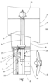
- the rudder 100 includes a trunk pipe 12 which is fixed in the hull 13 of the ship 11 .
- a rudder stock 14 is rotatably arranged in the trunk pipe 12 .
- a rudder blade 16 of the rudder 100 is attached to a lower end 15 of the rudder post 14 .
- the rudder blade 16 is arranged behind a propeller 17 of the ship 11 .
- the leading edge 18 of the rudder blade 16 faces the propeller 17 .
- a skeg 19 is arranged on the ship's hull 13, through which the trunk pipe 12 and the rudder stock 14 are guided.
- the lower end 15 of the rudder post 14 protrudes into the rudder blade 16 .
- the rudder blade 16 also has an articulated fin 20 which is arranged on a trailing strip 22 of the rudder blade 16 so that it can pivot by means of an articulation device 21 .
- the rudder blade 16 and the rudder post 14 are connected in the ship's hull 13 to a rudder system 23, by means of which the rudder post 14 and the rudder blade 16 connected to the rudder post 14 can be pivoted.
- the bottom end 24 of the trunk pipe 12 is also guided into the rudder blade 16 .
- In the lower end 24 of the tailpipe 12 there is a bearing bushing 32 on which the rudder stock 14 is mounted.
- the rudder 100 has one in the Figures 2 to 8 Bearing play measuring device 25 shown in more detail.
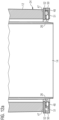
- the bearing play measuring device 25 has sensors 26 for the abrasion-free measurement of a bearing play, which are arranged over a circumference of the lower end 24 of the trunk pipe 12 .
- the sensors 26 are connected to an evaluation unit (not shown in detail) and arranged in the ship's hull 13 via signal transmission means 28 for data transmission.
- the signal routing means 28 formed as cables 29, which are arranged to run on an outer side 27 of the trunk pipe 12.
- the signal conduction channel 30 is designed as a U-profile 31 which is welded onto the outside 27 of the trunk pipe 12 and is filled with grease.
- the cable 29 running in the U-profile 31 is protected by the fat from vibrations and external and environmental influences.
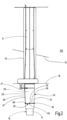
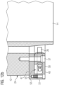
- the rudder stock 14 of the rudder 100 is rotatably mounted in the trunk 12 by means of a bearing bushing 32 firmly fixed to the trunk 12.
- the at least one sensor 26 is arranged above the bearing bush 32 as seen in an axial direction 33 of the rudder stock 14 .
- the at least one sensor 26 is connected to the evaluation unit via the signal routing means 28 embodied as a cable 29 .
- the sensor 26 is arranged in a sensor mount 34 , which is designed as a drilled hole 35 , and is screwed into the sensor mount 34 .
- the sensor 26 is designed as an eddy current sensor 36 and thus has a coil, not shown in detail.
- a magnetic field is generated, which induces an eddy current in the rudder stock 14 formed opposite the eddy current sensor 36, which in turn induces a magnetic field.
- the induced magnetic field acts back on the coil of the eddy current sensor 36 and changes the impedance of the coil, which can be measured as a change in the amplitude and the phase position of the coil of the eddy current sensor 36 and can be tapped off as a measurable variable.
- the distance 37 of the eddy current sensor 36 from the rudder post 14 can be inferred from the change in the phase position or amplitude of the coil.
- the eddy current sensor 36 is arranged without contact and at a distance from the rudder stock 14 . Seen in the axial direction 33 , the eddy current sensor 36 is arranged at a minimum distance 39 above the bearing bush 32 so that the material of the bearing bush 32 does not falsify the eddy current measurement of the eddy current sensor 36 .
- the signal-conducting means designed as a cable 19 is guided in the signal-conducting means channel 30 .
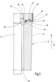
- the bearing play measuring device 25 of FIG 4 also includes a sensor 26 which is arranged in a sensor receptacle 34 of the coker tube 12.
- the sensor 26 is the 4 designed as an ultrasonic sensor 40 and arranged in direct physical contact on an outer side 41 of the bearing bush 32 .
- An ultrasonic contact means 42 based on silicone is arranged between the bearing bushing 32 , which is in particular arranged fixedly in the coker tube 12 , and the ultrasonic sensor 40 .
- the ultrasonic sensor 42 emits ultrasonic waves, which run through the material of the bearing bush 32 and are reflected by the interface 46 between the bearing bush 32 and the rudder post 14 .
- the wall thickness 43 of the bearing bushing 32 can be inferred from the transit time of the ultrasonic waves.
- the bearing clearance measuring device 25 of 4 identical to the bearing clearance measuring device 25 of 3 built up.
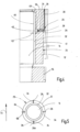
- figure 5 shows a cross section through the coker tube 12 of FIG 4 at the height of the bearing clearance measuring device 25.
- Four sensors 26 are arranged in the liner tube 12 at equal angular intervals over the circumference of the liner tube 12.
- the rudder post 14 is mounted in the trunk pipe 21 via a bearing bushing 32 .
- a sensor 26a of the sensors 26 is arranged exactly aft of the trunk pipe 12 opposite to the direction of travel 44 of the watercraft 10 .
- the angular distances between the sensors 26 are 90° in each case.
- FIG. 6 shows an alternative arrangement of the sensors 26, 26a of the bearing clearance measuring device 25.
- three sensors 26 are provided, which are arranged in sensor receptacles 34 .
- the three sensors 26, 26a are arranged at equal angular intervals over the circumference of the coker tube 12.
- the angular distances between the individual sensors 26, 26a are 120°. Even with the design 6 a sensor 26a is fastened to the coker pipe 12 exactly opposite to the direction of travel 44 astern.
- FIG. 7 shows a further embodiment of the bearing clearance measuring device 25 with eddy current sensors 36.
- the eddy current sensors 36 are arranged on an annular holder 45.
- the ring-shaped holder 45 is arranged on an end face 47 of the lower end 24 of the coker tube 12 .
- the eddy current sensors 36 are located in seen in the axial direction 33 of the rudder stock 14 below the bearing bush 32.
- the configuration is 7 analogous to the design 3 .
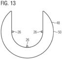
- 9 12 shows a further holder 48, which is arranged on the end face 47 of the trunk tube 12, in a plan view of the end face 47 of the lower end 24 of the trunk tube 12.
- the holder 48 comprises two ring segments 50 designed as quarter rings 49.
- Each of the ring segments 50 covers an angular range of slightly more than 90°.
- Each ring segment 50 has two sensors 26 which can be embodied as eddy current sensors 36 .
- the sensors 26 of each ring segment 50 are arranged at an angular distance of 90° from one another.
- the configuration shown with two ring segments 50 designed as quarter rings 49 is particularly suitable as a retrofit solution for an existing rudder 100 with existing rudder stocks 14 .
- a single ring segment 50 off 9 is in 10 shown.
- the ring segment 50 is designed in two parts and has a base body 51 and a cover 52 .
- the cover 52 is screwed to the base body 51 .
- two sensors 26 protrude inward in a radial direction 58 for measuring a bearing clearance from the ring segment 50 without abrasion.
- a signal connection 54 is provided on one of the end faces 53 of the ring segment 50 , via which the signals and data from the two sensors 26 can be led out of the ring segment 50 .
- Signal routing means 28 ( 2 ) are connected, with which the signals and data of the sensors 26 can be routed to an evaluation unit.
- FIG. 11 shows the holder 48 with the two ring segments 50 in a top view 9 , But without the coker tube 12.
- Both ring segments 50 have according to 10 a base body 51 on.
- the ring segments 50 are shown without the respective cover 52.
- Each of the ring segments 50 has an interior space 55 in which the sensors 26 are at least partially arranged.
- Each of the sensors 26 is connected to a sensor cable 56 connected, which leads the signals and data of the sensors 26 to the signal connection 54 on the end face 53 of the respective ring segment 50.
- the interior 55 of the ring segments 50 is filled with grease in order to protect the sensor cable 56 from vibrations.
- FIG. 12a and 12b 12 show a side view of the lower end 24 of the coker tube 12 similar to FIG figure 7 .
- Figure 12b is a detailed view of the 12a .
- the ring segments 50 of the holder 48 are arranged on the end face 47 of the lower end 24 of the coker tube 12 .
- the sensors 26 protrude from the inner space 55 of the respective ring segment 50 for the abrasion-free measurement of the bearing play.
- the ring segments 50 are screwed to the end face 47 of the coker tube 12 by means of connecting screws 57 .
- Each ring segment 50 has a base body 51 and a cover 52 .
- the holder 48 is designed as an approximately U-shaped ring segment 50 .
- the ring segment 50 includes sensors 26 for measuring the bearing clearance without abrasion.
Landscapes
- Engineering & Computer Science (AREA)
- Physics & Mathematics (AREA)
- General Physics & Mathematics (AREA)
- Mechanical Engineering (AREA)
- General Engineering & Computer Science (AREA)
- Combustion & Propulsion (AREA)
- Chemical & Material Sciences (AREA)
- Ocean & Marine Engineering (AREA)
- Measurement Of Length, Angles, Or The Like Using Electric Or Magnetic Means (AREA)
- Length Measuring Devices With Unspecified Measuring Means (AREA)
- Sliding-Contact Bearings (AREA)
- Support Of The Bearing (AREA)
- A Measuring Device Byusing Mechanical Method (AREA)
- Switches With Compound Operations (AREA)
Priority Applications (8)
| Application Number | Priority Date | Filing Date | Title |
|---|---|---|---|
| HRP20230700TT HRP20230700T1 (hr) | 2019-03-13 | 2020-02-28 | Kormilo za vodena vozila sa uređajem za mjerenje zazora ležaja, postupak za mjerenje zazora ležaja u kormilu i uređaj za mjerenje zazora ležaja za kormilo |
| US16/814,246 US11447225B2 (en) | 2019-03-13 | 2020-03-10 | Rudder for watercraft with a bearing clearance measuring device, method for measurement of a bearing clearance in a rudder and bearing clearance measuring device for a rudder |
| SG10202002177PA SG10202002177PA (en) | 2019-03-13 | 2020-03-10 | Rudder for watercraft with a bearing clearance measuring device, method for measurement of a bearing clearance in a rudder and bearing clearance measuring devicefor a rudder |
| CA3075133A CA3075133A1 (en) | 2019-03-13 | 2020-03-11 | Rudder for watercraft with a bearing clearance measuring device, method for measurement of a bearing clearance in a rudder and bearing clearance measuring device for a rudder |
| JP2020041489A JP7409749B2 (ja) | 2019-03-13 | 2020-03-11 | 軸受隙間測定装置を有する水中又は水上移動体の舵、舵の軸受隙間の測定方法及び舵の軸受隙間測定装置 |
| TW109108007A TWI849078B (zh) | 2019-03-13 | 2020-03-11 | 水運工具的舵、舵中的軸承間隙測量方法和測量裝置 |
| KR1020200031185A KR102808967B1 (ko) | 2019-03-13 | 2020-03-13 | 베어링 간극 측정 장치를 구비한 워터크래프트용 러더, 러더에서의 베어링 간극을 측정하는 방법, 그리고 러더를 위한 베어링 간극 측정 장치 |
| CN202010176696.9A CN111688899B (zh) | 2019-03-13 | 2020-03-13 | 水运工具的舵、舵中的轴承间隙测量方法和测量装置 |
Applications Claiming Priority (1)
| Application Number | Priority Date | Filing Date | Title |
|---|---|---|---|
| EP19162575 | 2019-03-13 |
Publications (3)
| Publication Number | Publication Date |
|---|---|
| EP3708482A1 EP3708482A1 (de) | 2020-09-16 |
| EP3708482B1 true EP3708482B1 (de) | 2023-06-07 |
| EP3708482C0 EP3708482C0 (de) | 2023-06-07 |
Family
ID=65812055
Family Applications (1)
| Application Number | Title | Priority Date | Filing Date |
|---|---|---|---|
| EP20160036.8A Active EP3708482B1 (de) | 2019-03-13 | 2020-02-28 | Ruder für wasserfahrzeuge mit einer lagerspielmessvorrichtung, verfahren zur messung eines lagerspiels in einem ruder und lagerspielmessvorrichtung für ein ruder |
Country Status (11)
Families Citing this family (9)
| Publication number | Priority date | Publication date | Assignee | Title |
|---|---|---|---|---|
| AT524189B1 (de) * | 2020-08-31 | 2022-06-15 | Miba Gleitlager Austria Gmbh | Lagerelement |
| CN112498625B (zh) * | 2020-10-30 | 2023-05-05 | 沪东中华造船(集团)有限公司 | 一种船舶悬挂舵舵承快速临时维修方法 |
| JP7645124B2 (ja) * | 2021-04-01 | 2025-03-13 | ジャパンマリンユナイテッド株式会社 | スラスト隙間計測装置、スラスト隙間計測方法及び船舶 |
| CN114148485B (zh) * | 2021-11-09 | 2022-12-30 | 中船澄西船舶修造有限公司 | 一种船舶底部漆面加工用上架支撑工装 |
| CN113945182A (zh) * | 2021-11-23 | 2022-01-18 | 中车长春轨道客车股份有限公司 | 一种齿轮箱大齿轮轴承游隙测量装置 |
| CN114295032B (zh) * | 2021-12-21 | 2024-12-27 | 广东中远海运重工有限公司 | 一种带螺纹调节杆的舵系衬套间隙测量装置及方法 |
| CN115384748A (zh) * | 2022-09-15 | 2022-11-25 | 重庆长源船舶设备有限公司 | 一种江用悬挂式襟翼舵 |
| CN116198101A (zh) * | 2023-01-16 | 2023-06-02 | 南京农业大学 | 机械关节间隙测量器 |
| CN116923681B (zh) * | 2023-07-18 | 2024-08-30 | 招商局重工(江苏)有限公司 | 一种舵系附体结构及其检测方法和设计方法 |
Family Cites Families (19)
| Publication number | Priority date | Publication date | Assignee | Title |
|---|---|---|---|---|
| JPS6052654B2 (ja) * | 1976-04-28 | 1985-11-20 | 株式会社安川電機 | 交流回転電機の軸受摩耗の検出装置 |
| US5001435A (en) * | 1987-04-27 | 1991-03-19 | Honeywell Inc. | Lubrication film thickness measuring system and method |
| US4924180A (en) * | 1987-12-18 | 1990-05-08 | Liquiflo Equipment Company | Apparatus for detecting bearing shaft wear utilizing rotatable magnet means |
| US5300841A (en) * | 1992-11-02 | 1994-04-05 | General Electric Company | Inductive air gap estimation method for active magnetic bearings |
| US5300842A (en) * | 1992-11-02 | 1994-04-05 | General Electric Company | Flux/current air gap estimation method for active magnetic bearings |
| JPH10252751A (ja) * | 1997-03-11 | 1998-09-22 | Matsushita Electric Ind Co Ltd | 動圧型流体軸受装置の調芯方法と調芯装置 |
| US6080982A (en) * | 1998-05-13 | 2000-06-27 | The United States Of America As Represented By The Secretary Of The Navy | Embedded wear sensor |
| JP2001021577A (ja) * | 1999-07-12 | 2001-01-26 | Nsk Ltd | 車輪支持用転がり軸受ユニット |
| DE19960738C1 (de) * | 1999-12-16 | 2001-08-23 | Lfk Gmbh | Ruderanbindung für Lenkflugkörper |
| JP2002181526A (ja) * | 2000-12-19 | 2002-06-26 | Mitsubishi Heavy Ind Ltd | 軸受隙間計測装置 |
| JP2002188411A (ja) | 2000-12-22 | 2002-07-05 | Mitsubishi Heavy Ind Ltd | 異常診断装置 |
| WO2005102835A1 (en) | 2004-04-26 | 2005-11-03 | Ab Volvo Penta | Arrangement and method for controlling a propeller drive on a boat |
| KR101034331B1 (ko) * | 2009-06-19 | 2011-05-16 | 대우조선해양 주식회사 | 선박의 러더 베어링 성능 검사 방법 |
| DE202010004191U1 (de) | 2010-03-23 | 2010-07-01 | Van Der Velden Barkemeyer Gmbh | Ruder für Schiffe |
| KR101228049B1 (ko) * | 2011-04-18 | 2013-01-30 | 현대중공업 주식회사 | 선박의 러더 스톡과 넥 베어링 사이의 틈새 검사 방법. |
| DE102014110383A1 (de) | 2014-04-01 | 2015-10-01 | Becker Marine Systems Gmbh & Co. Kg | Lager zum Lagern einer Welle, insbesondere eines Ruderschaftes, elektronische Lagerspielmessvorrichtung, Ruder umfassend ein Lager zum Lagern einer Welle und Verfahren zur Messung eines Verschleißes eines Lagers zum Lagern einer Welle |
| JP6723634B2 (ja) * | 2016-01-20 | 2020-07-15 | 三菱重工業株式会社 | 隙間計測装置及び隙間計測方法 |
| US10234375B2 (en) * | 2016-09-15 | 2019-03-19 | Saudi Arabian Oil Company | Integrated ultrasonic testing and cathodic protection measurement probe |
| US10989529B2 (en) * | 2016-09-15 | 2021-04-27 | Saudi Arabian Oil Company | Magnetically coupled integrated ultrasonic testing and cathodic protection measurement probe |
-
2020
- 2020-02-28 EP EP20160036.8A patent/EP3708482B1/de active Active
- 2020-02-28 HR HRP20230700TT patent/HRP20230700T1/hr unknown
- 2020-02-28 ES ES20160036T patent/ES2951937T3/es active Active
- 2020-02-28 PL PL20160036.8T patent/PL3708482T3/pl unknown
- 2020-03-10 US US16/814,246 patent/US11447225B2/en active Active
- 2020-03-10 SG SG10202002177PA patent/SG10202002177PA/en unknown
- 2020-03-11 CA CA3075133A patent/CA3075133A1/en active Pending
- 2020-03-11 JP JP2020041489A patent/JP7409749B2/ja active Active
- 2020-03-11 TW TW109108007A patent/TWI849078B/zh active
- 2020-03-13 CN CN202010176696.9A patent/CN111688899B/zh active Active
- 2020-03-13 KR KR1020200031185A patent/KR102808967B1/ko active Active
Also Published As
| Publication number | Publication date |
|---|---|
| ES2951937T3 (es) | 2023-10-25 |
| TWI849078B (zh) | 2024-07-21 |
| KR20200110241A (ko) | 2020-09-23 |
| SG10202002177PA (en) | 2020-10-29 |
| PL3708482T3 (pl) | 2023-09-11 |
| KR102808967B1 (ko) | 2025-05-15 |
| CN111688899A (zh) | 2020-09-22 |
| US11447225B2 (en) | 2022-09-20 |
| JP7409749B2 (ja) | 2024-01-09 |
| EP3708482C0 (de) | 2023-06-07 |
| CA3075133A1 (en) | 2020-09-13 |
| US20200290715A1 (en) | 2020-09-17 |
| TW202035229A (zh) | 2020-10-01 |
| EP3708482A1 (de) | 2020-09-16 |
| JP2020147278A (ja) | 2020-09-17 |
| HRP20230700T1 (hr) | 2023-10-13 |
| CN111688899B (zh) | 2024-05-03 |
Similar Documents
| Publication | Publication Date | Title |
|---|---|---|
| EP3708482B1 (de) | Ruder für wasserfahrzeuge mit einer lagerspielmessvorrichtung, verfahren zur messung eines lagerspiels in einem ruder und lagerspielmessvorrichtung für ein ruder | |
| EP3126687B1 (de) | Lager zum lagern einer welle, insbesondere eines ruderschaftes, oder eines ruderblattes, elektronische lagerspielmessvorrichtung, ruder umfassend ein lager zum lagern einer welle oder eines ruderblattes und verfahren zur messung eines verschleisses eines lagers zum lagern einer welle oder eines ruderblattes | |
| EP2319758B1 (de) | Anordnung zur Ermittlung einer auf ein Ruder wirkenden Kraft | |
| DE2407918B2 (de) | Einrichtung zur Bestimmung der räumlichen Lage eines seeseismischen Schleppkabels | |
| DE202010004191U1 (de) | Ruder für Schiffe | |
| DE102018123799A1 (de) | Gurtabstreifer und Verfahren zum Betrieb eines Gurtabstreifers | |
| EP3187849B1 (de) | System zur bestimmung eines biegemoments an einem ruder und verfahren zur bestimmung einer leistung an einem ruder | |
| CH710485A2 (de) | Sonden für ein Inspektionssystem für ein im wesentlichen rundes Loch. | |
| DE102018109085A1 (de) | Antriebsanordnung zur Kompensation und/oder zur Minderung und/oder zur Verringerung der Rollbewegung und/oder der Stampfbewegung eines Wasserfahrzeuges | |
| DE202014007542U1 (de) | Vorrichtung zur radargestützten Inspektion von erdverlegten Kanalrohren | |
| WO2012098150A1 (de) | Ruder für schiffe mit einer ruderüberwachungsvorrichtung | |
| EP0993593B1 (de) | Vorrichtung zur inhaltskontrolle eines behälters | |
| AT524361B1 (de) | Wälzlageranordnung | |
| DE60116648T4 (de) | Axial einsetzbarer schublager für strahlantriebseinheiten | |
| DE102011079348A1 (de) | Wechselarmatur | |
| DE102005060674C5 (de) | Positionssensor in Stabbauweise sowie Verfahren zum Austausch | |
| DE4329521A1 (de) | Vorrichtung zur Messung von Rotordaten bei Hubschraubern mit gelenklosen Rotoren zur Bestimmung von Roll- und Nickbeschleunigungen | |
| EP3964328A1 (de) | Überprüfung eines werkzeugs einer werkzeugmaschine | |
| DE202013104463U1 (de) | Ruder für Schiffe | |
| DE2929420B1 (de) | Trimmgeber fuer Motorboote | |
| DE69420729T2 (de) | System mit einer positionsanzeige und methode zum abtasten einer oberfläche von hand mit einem sensor | |
| DE102012220921B4 (de) | Unterseeboot | |
| DE2639192C3 (de) | Einrichtung zur Tiefgangermittlung eines Schiffes | |
| DE102013114240A1 (de) | Füllstandmessgerät mit einem beweglichen Antennenträger | |
| DE10007737C2 (de) | Verstellpropeller, insbesondere für Motor- und Sportboote |
Legal Events
| Date | Code | Title | Description |
|---|---|---|---|
| REG | Reference to a national code |
Ref country code: HR Ref legal event code: TUEP Ref document number: P20230700T Country of ref document: HR |
|
| PUAI | Public reference made under article 153(3) epc to a published international application that has entered the european phase |
Free format text: ORIGINAL CODE: 0009012 |
|
| STAA | Information on the status of an ep patent application or granted ep patent |
Free format text: STATUS: THE APPLICATION HAS BEEN PUBLISHED |
|
| AK | Designated contracting states |
Kind code of ref document: A1 Designated state(s): AL AT BE BG CH CY CZ DE DK EE ES FI FR GB GR HR HU IE IS IT LI LT LU LV MC MK MT NL NO PL PT RO RS SE SI SK SM TR |
|
| AX | Request for extension of the european patent |
Extension state: BA ME |
|
| STAA | Information on the status of an ep patent application or granted ep patent |
Free format text: STATUS: REQUEST FOR EXAMINATION WAS MADE |
|
| 17P | Request for examination filed |
Effective date: 20201205 |
|
| RBV | Designated contracting states (corrected) |
Designated state(s): AL AT BE BG CH CY CZ DE DK EE ES FI FR GB GR HR HU IE IS IT LI LT LU LV MC MK MT NL NO PL PT RO RS SE SI SK SM TR |
|
| STAA | Information on the status of an ep patent application or granted ep patent |
Free format text: STATUS: EXAMINATION IS IN PROGRESS |
|
| RIC1 | Information provided on ipc code assigned before grant |
Ipc: B63H 25/52 20060101AFI20210503BHEP Ipc: F16C 17/02 20060101ALI20210503BHEP Ipc: F16C 17/24 20060101ALI20210503BHEP Ipc: G01B 5/14 20060101ALI20210503BHEP Ipc: G01N 3/56 20060101ALI20210503BHEP Ipc: B63H 25/38 20060101ALI20210503BHEP |
|
| 17Q | First examination report despatched |
Effective date: 20210531 |
|
| GRAP | Despatch of communication of intention to grant a patent |
Free format text: ORIGINAL CODE: EPIDOSNIGR1 |
|
| STAA | Information on the status of an ep patent application or granted ep patent |
Free format text: STATUS: GRANT OF PATENT IS INTENDED |
|
| INTG | Intention to grant announced |
Effective date: 20220922 |
|
| GRAS | Grant fee paid |
Free format text: ORIGINAL CODE: EPIDOSNIGR3 |
|
| GRAA | (expected) grant |
Free format text: ORIGINAL CODE: 0009210 |
|
| STAA | Information on the status of an ep patent application or granted ep patent |
Free format text: STATUS: THE PATENT HAS BEEN GRANTED |
|
| AK | Designated contracting states |
Kind code of ref document: B1 Designated state(s): AL AT BE BG CH CY CZ DE DK EE ES FI FR GB GR HR HU IE IS IT LI LT LU LV MC MK MT NL NO PL PT RO RS SE SI SK SM TR |
|
| REG | Reference to a national code |
Ref country code: GB Ref legal event code: FG4D Free format text: NOT ENGLISH |
|
| REG | Reference to a national code |
Ref country code: CH Ref legal event code: EP Ref country code: AT Ref legal event code: REF Ref document number: 1574244 Country of ref document: AT Kind code of ref document: T Effective date: 20230615 |
|
| REG | Reference to a national code |
Ref country code: DE Ref legal event code: R096 Ref document number: 502020003441 Country of ref document: DE |
|
| P01 | Opt-out of the competence of the unified patent court (upc) registered |
Effective date: 20230529 |
|
| U01 | Request for unitary effect filed |
Effective date: 20230620 |
|
| U07 | Unitary effect registered |
Designated state(s): AT BE BG DE DK EE FI FR IT LT LU LV MT NL PT SE SI Effective date: 20230627 |
|
| REG | Reference to a national code |
Ref country code: NO Ref legal event code: T2 Effective date: 20230607 |
|
| P04 | Withdrawal of opt-out of the competence of the unified patent court (upc) registered |
Effective date: 20230623 |
|
| REG | Reference to a national code |
Ref country code: GR Ref legal event code: EP Ref document number: 20230401015 Country of ref document: GR Effective date: 20230808 |
|
| REG | Reference to a national code |
Ref country code: LT Ref legal event code: MG9D |
|
| REG | Reference to a national code |
Ref country code: HR Ref legal event code: T1PR Ref document number: P20230700 Country of ref document: HR |
|
| REG | Reference to a national code |
Ref country code: ES Ref legal event code: FG2A Ref document number: 2951937 Country of ref document: ES Kind code of ref document: T3 Effective date: 20231025 |
|
| PG25 | Lapsed in a contracting state [announced via postgrant information from national office to epo] |
Ref country code: RS Free format text: LAPSE BECAUSE OF FAILURE TO SUBMIT A TRANSLATION OF THE DESCRIPTION OR TO PAY THE FEE WITHIN THE PRESCRIBED TIME-LIMIT Effective date: 20230607 |
|
| PG25 | Lapsed in a contracting state [announced via postgrant information from national office to epo] |
Ref country code: SK Free format text: LAPSE BECAUSE OF FAILURE TO SUBMIT A TRANSLATION OF THE DESCRIPTION OR TO PAY THE FEE WITHIN THE PRESCRIBED TIME-LIMIT Effective date: 20230607 |
|
| PG25 | Lapsed in a contracting state [announced via postgrant information from national office to epo] |
Ref country code: IS Free format text: LAPSE BECAUSE OF FAILURE TO SUBMIT A TRANSLATION OF THE DESCRIPTION OR TO PAY THE FEE WITHIN THE PRESCRIBED TIME-LIMIT Effective date: 20231007 |
|
| PG25 | Lapsed in a contracting state [announced via postgrant information from national office to epo] |
Ref country code: SM Free format text: LAPSE BECAUSE OF FAILURE TO SUBMIT A TRANSLATION OF THE DESCRIPTION OR TO PAY THE FEE WITHIN THE PRESCRIBED TIME-LIMIT Effective date: 20230607 Ref country code: SK Free format text: LAPSE BECAUSE OF FAILURE TO SUBMIT A TRANSLATION OF THE DESCRIPTION OR TO PAY THE FEE WITHIN THE PRESCRIBED TIME-LIMIT Effective date: 20230607 Ref country code: RO Free format text: LAPSE BECAUSE OF FAILURE TO SUBMIT A TRANSLATION OF THE DESCRIPTION OR TO PAY THE FEE WITHIN THE PRESCRIBED TIME-LIMIT Effective date: 20230607 Ref country code: IS Free format text: LAPSE BECAUSE OF FAILURE TO SUBMIT A TRANSLATION OF THE DESCRIPTION OR TO PAY THE FEE WITHIN THE PRESCRIBED TIME-LIMIT Effective date: 20231007 Ref country code: CZ Free format text: LAPSE BECAUSE OF FAILURE TO SUBMIT A TRANSLATION OF THE DESCRIPTION OR TO PAY THE FEE WITHIN THE PRESCRIBED TIME-LIMIT Effective date: 20230607 |
|
| REG | Reference to a national code |
Ref country code: DE Ref legal event code: R097 Ref document number: 502020003441 Country of ref document: DE |
|
| REG | Reference to a national code |
Ref country code: HR Ref legal event code: ODRP Ref document number: P20230700 Country of ref document: HR Payment date: 20240223 Year of fee payment: 5 |
|
| U20 | Renewal fee for the european patent with unitary effect paid |
Year of fee payment: 5 Effective date: 20240228 |
|
| PLBE | No opposition filed within time limit |
Free format text: ORIGINAL CODE: 0009261 |
|
| STAA | Information on the status of an ep patent application or granted ep patent |
Free format text: STATUS: NO OPPOSITION FILED WITHIN TIME LIMIT |
|
| 26N | No opposition filed |
Effective date: 20240308 |
|
| PG25 | Lapsed in a contracting state [announced via postgrant information from national office to epo] |
Ref country code: MC Free format text: LAPSE BECAUSE OF FAILURE TO SUBMIT A TRANSLATION OF THE DESCRIPTION OR TO PAY THE FEE WITHIN THE PRESCRIBED TIME-LIMIT Effective date: 20230607 |
|
| REG | Reference to a national code |
Ref country code: CH Ref legal event code: PL |
|
| PG25 | Lapsed in a contracting state [announced via postgrant information from national office to epo] |
Ref country code: CH Free format text: LAPSE BECAUSE OF NON-PAYMENT OF DUE FEES Effective date: 20240229 |
|
| PG25 | Lapsed in a contracting state [announced via postgrant information from national office to epo] |
Ref country code: CH Free format text: LAPSE BECAUSE OF NON-PAYMENT OF DUE FEES Effective date: 20240229 |
|
| P05 | Withdrawal of opt-out of the competence of the unified patent court (upc) changed |
Free format text: CASE NUMBER: APP_526863/2023 Effective date: 20230627 |
|
| PG25 | Lapsed in a contracting state [announced via postgrant information from national office to epo] |
Ref country code: IE Free format text: LAPSE BECAUSE OF NON-PAYMENT OF DUE FEES Effective date: 20240228 |
|
| PG25 | Lapsed in a contracting state [announced via postgrant information from national office to epo] |
Ref country code: IE Free format text: LAPSE BECAUSE OF NON-PAYMENT OF DUE FEES Effective date: 20240228 |
|
| REG | Reference to a national code |
Ref country code: HR Ref legal event code: ODRP Ref document number: P20230700 Country of ref document: HR Payment date: 20250218 Year of fee payment: 6 |
|
| U20 | Renewal fee for the european patent with unitary effect paid |
Year of fee payment: 6 Effective date: 20250227 |
|
| PGFP | Annual fee paid to national office [announced via postgrant information from national office to epo] |
Ref country code: HR Payment date: 20250218 Year of fee payment: 6 |
|
| PGFP | Annual fee paid to national office [announced via postgrant information from national office to epo] |
Ref country code: ES Payment date: 20250318 Year of fee payment: 6 |
|
| PGFP | Annual fee paid to national office [announced via postgrant information from national office to epo] |
Ref country code: NO Payment date: 20250221 Year of fee payment: 6 |
|
| PGFP | Annual fee paid to national office [announced via postgrant information from national office to epo] |
Ref country code: GR Payment date: 20250220 Year of fee payment: 6 |
|
| PGFP | Annual fee paid to national office [announced via postgrant information from national office to epo] |
Ref country code: PL Payment date: 20250218 Year of fee payment: 6 |
|
| PGFP | Annual fee paid to national office [announced via postgrant information from national office to epo] |
Ref country code: GB Payment date: 20250218 Year of fee payment: 6 |
|
| PGFP | Annual fee paid to national office [announced via postgrant information from national office to epo] |
Ref country code: TR Payment date: 20250219 Year of fee payment: 6 |
|
| PG25 | Lapsed in a contracting state [announced via postgrant information from national office to epo] |
Ref country code: CY Free format text: LAPSE BECAUSE OF FAILURE TO SUBMIT A TRANSLATION OF THE DESCRIPTION OR TO PAY THE FEE WITHIN THE PRESCRIBED TIME-LIMIT; INVALID AB INITIO Effective date: 20200228 |
|
| PG25 | Lapsed in a contracting state [announced via postgrant information from national office to epo] |
Ref country code: HU Free format text: LAPSE BECAUSE OF FAILURE TO SUBMIT A TRANSLATION OF THE DESCRIPTION OR TO PAY THE FEE WITHIN THE PRESCRIBED TIME-LIMIT; INVALID AB INITIO Effective date: 20200228 |