EP3708201A1 - Gerinnselfaenger, externe funktionseinrichtung, blutkreislauf sowie behandlungsvorrichtung - Google Patents
Gerinnselfaenger, externe funktionseinrichtung, blutkreislauf sowie behandlungsvorrichtung Download PDFInfo
- Publication number
- EP3708201A1 EP3708201A1 EP20164806.0A EP20164806A EP3708201A1 EP 3708201 A1 EP3708201 A1 EP 3708201A1 EP 20164806 A EP20164806 A EP 20164806A EP 3708201 A1 EP3708201 A1 EP 3708201A1
- Authority
- EP
- European Patent Office
- Prior art keywords
- clot
- clot catcher
- passage openings
- catcher
- housing
- Prior art date
- Legal status (The legal status is an assumption and is not a legal conclusion. Google has not performed a legal analysis and makes no representation as to the accuracy of the status listed.)
- Granted
Links
Images



Classifications
-
- A—HUMAN NECESSITIES
- A61—MEDICAL OR VETERINARY SCIENCE; HYGIENE
- A61M—DEVICES FOR INTRODUCING MEDIA INTO, OR ONTO, THE BODY; DEVICES FOR TRANSDUCING BODY MEDIA OR FOR TAKING MEDIA FROM THE BODY; DEVICES FOR PRODUCING OR ENDING SLEEP OR STUPOR
- A61M5/00—Devices for bringing media into the body in a subcutaneous, intra-vascular or intramuscular way; Accessories therefor, e.g. filling or cleaning devices, arm rests
- A61M5/14—Infusion devices, e.g. infusing by gravity; Blood infusion; Accessories therefor
- A61M5/165—Filtering accessories, e.g. blood filters, filters for infusion liquids
-
- A—HUMAN NECESSITIES
- A61—MEDICAL OR VETERINARY SCIENCE; HYGIENE
- A61M—DEVICES FOR INTRODUCING MEDIA INTO, OR ONTO, THE BODY; DEVICES FOR TRANSDUCING BODY MEDIA OR FOR TAKING MEDIA FROM THE BODY; DEVICES FOR PRODUCING OR ENDING SLEEP OR STUPOR
- A61M1/00—Suction or pumping devices for medical purposes; Devices for carrying-off, for treatment of, or for carrying-over, body-liquids; Drainage systems
- A61M1/36—Other treatment of blood in a by-pass of the natural circulatory system, e.g. temperature adaptation, irradiation ; Extra-corporeal blood circuits
- A61M1/3621—Extra-corporeal blood circuits
- A61M1/3622—Extra-corporeal blood circuits with a cassette forming partially or totally the blood circuit
- A61M1/36226—Constructional details of cassettes, e.g. specific details on material or shape
- A61M1/362263—Details of incorporated filters
- A61M1/362264—Details of incorporated filters the filter being a blood filter
-
- A—HUMAN NECESSITIES
- A61—MEDICAL OR VETERINARY SCIENCE; HYGIENE
- A61M—DEVICES FOR INTRODUCING MEDIA INTO, OR ONTO, THE BODY; DEVICES FOR TRANSDUCING BODY MEDIA OR FOR TAKING MEDIA FROM THE BODY; DEVICES FOR PRODUCING OR ENDING SLEEP OR STUPOR
- A61M1/00—Suction or pumping devices for medical purposes; Devices for carrying-off, for treatment of, or for carrying-over, body-liquids; Drainage systems
- A61M1/36—Other treatment of blood in a by-pass of the natural circulatory system, e.g. temperature adaptation, irradiation ; Extra-corporeal blood circuits
- A61M1/3621—Extra-corporeal blood circuits
- A61M1/3627—Degassing devices; Buffer reservoirs; Drip chambers; Blood filters
-
- A—HUMAN NECESSITIES
- A61—MEDICAL OR VETERINARY SCIENCE; HYGIENE
- A61M—DEVICES FOR INTRODUCING MEDIA INTO, OR ONTO, THE BODY; DEVICES FOR TRANSDUCING BODY MEDIA OR FOR TAKING MEDIA FROM THE BODY; DEVICES FOR PRODUCING OR ENDING SLEEP OR STUPOR
- A61M1/00—Suction or pumping devices for medical purposes; Devices for carrying-off, for treatment of, or for carrying-over, body-liquids; Drainage systems
- A61M1/36—Other treatment of blood in a by-pass of the natural circulatory system, e.g. temperature adaptation, irradiation ; Extra-corporeal blood circuits
- A61M1/3621—Extra-corporeal blood circuits
- A61M1/3622—Extra-corporeal blood circuits with a cassette forming partially or totally the blood circuit
- A61M1/36226—Constructional details of cassettes, e.g. specific details on material or shape
-
- A—HUMAN NECESSITIES
- A61—MEDICAL OR VETERINARY SCIENCE; HYGIENE
- A61M—DEVICES FOR INTRODUCING MEDIA INTO, OR ONTO, THE BODY; DEVICES FOR TRANSDUCING BODY MEDIA OR FOR TAKING MEDIA FROM THE BODY; DEVICES FOR PRODUCING OR ENDING SLEEP OR STUPOR
- A61M2205/00—General characteristics of the apparatus
- A61M2205/12—General characteristics of the apparatus with interchangeable cassettes forming partially or totally the fluid circuit
- A61M2205/125—General characteristics of the apparatus with interchangeable cassettes forming partially or totally the fluid circuit with incorporated filters
Definitions
- the present invention relates to a clot trap according to the preamble of claim 1. It also relates to an external functional device according to claim 13, a blood circuit as disclosed herein, and a treatment device according to claim 15.
- Clot catchers are i.a. used in extracorporeal blood circuits in order to catch or hold back clots or thrombi that are present in the extracorporeal blood stream.
- An object of the present invention is to provide a further clot trap.
- the clot catcher according to the invention has a sieve surface or a clot catcher surface, which is suitable and provided for collecting clots of a fluid flowing through the sieve surface.
- sieve surface denotes a device or component of the clot trap which is intended to prevent the clot from passing through the clot trap.
- the sieve surface is preferably a device with a mechanically effective sieve or filter effect without being limited thereto.
- the screen surface can also be suitable and provided for retaining or dissolving clots, for example in a physical and / or chemical manner.
- the screen surface is designed in the form of a disk.
- disk-shaped as used herein means that the sieve surface - preferably essentially or completely - is designed in the form of a disk.
- a fluid flowing through the clot trap enters the clot trap - in full or in part - on an inflow side, flows through the screen surface and exits the clot trap on an outflow side.
- clots include e.g. To understand thrombi, solid impurities and the like.
- fluid includes, but is not limited to, liquids such as medicinal fluids, e.g. Blood, gases, emulsions, suspensions, dispersions and the like and mixtures thereof.
- the disk shape of the screen surface can be uneven and / or wavy, curved or the like in each embodiment according to the invention. Alternatively, it can be flat - in the sense of being flat or lying in one plane.
- the disk shape indicates a structure which is significantly larger in a first dimension (the main extension) than in a direction perpendicular to it.
- the clot catcher is arranged essentially vertically during or for its use - preferably in relation to the main extent of the sieve surface -, as shown for example in FIG Fig. 6 is shown.
- substantially perpendicular means that the inclination of the clot catcher relative to the vertical may be a maximum of about 15 ° in all directions or a maximum inclination of +/- 15 ° is particularly preferred. An inclination of less than +/- 15 ° is also preferred. Such a possibility of inclination to z. B. 15 ° clockwise or 15 ° counterclockwise or forwards or backwards, or to one side (ie against each direction) is partly in the Fig. 4 and 7th indicated.
- the clot catcher can be arranged at any angle or at any incline with respect to the center of the earth.
- a chemical filter or sieve effect can be achieved in that the clots are chemically bound to the sieve surface and / or in the sieve surface, for example in the pores of the same.
- the clots can be reversibly or irreversibly bound to the screen surface.
- the clots can be physically adsorbed onto the screen surface.
- the clots can also be completely or partially dissolved on the sieve surface.
- the screen surface has passage openings through which the fluid can flow from the inflow side to the outflow side.
- a mechanical filter or sieve effect can be achieved with the aid of the passage openings.
- the dimensions of the passage openings or a mesh size of the screen surface can be selected such that the clots are retained on the inflow side of the inflowing fluids due to their size.
- the passage openings of the screen surface together form an open total passage surface of the screen surface.
- the dimensions of the passage openings can be selected so that clots, agglomerates, solid particles and the like present in the flowing fluid or fluid stream are retained on the inflow side of the fluid from the fluid flow due to their size and do not reach the outflow side of the clot catcher.
- all of the passage openings are arranged on — in particular concentric — circles or segments of a circle.
- An exemplary arrangement is shown below in Fig. 1 shown.
- all or only some of the passage openings are arranged radially in relation to a center point of the clot catcher or the sieve surface.
- center point denotes a center point or a point in a central area of the disc-shaped sieve surface and / or of the clot catcher. This center point can correspond to the center of gravity or the geometric center of gravity of the sieve surface and / or the clot catcher and / or a circle center point of a round sieve surface and / or the clot catcher.
- the passage openings are provided in a "radial" arrangement in such a way that they extend in the radial direction from the center of the screen surface or the clot catcher, in particular in one or more planes which are parallel to a main plane of extent of the screen surface.
- a number of passage openings are arranged on the entire screen surface.
- the passage openings can be arranged distributed over the screen surface at the same distance from one another.
- the passage openings can be arranged offset from one another, as is the case, for example, in FIG Fig. 2 is shown.
- the passage openings can be arranged symmetrically on the sieve surface in relation to the center point of the sieve surface and / or the clot catcher. However, they can also be arranged asymmetrically on the screen surface.
- At least one section of the screen surface has no passage openings or, compared to other areas of the screen surface, a smaller number of passage openings.
- the section without - or with comparatively few - passage openings can face the outflow area of the clot catcher or of a housing in which the clot catcher is accommodated.
- This section can be in the shape of a segment of a circle.
- the circumference of the partial circular arc is preferably located downstream of a tip of the partial circular arc in a position of use of the clot catcher.
- the passage opening (s) can have any suitable geometric shape. For example, they can be angular, round and / or elliptical or the like.
- a number of passage openings can, for example, have sharp edges on at least one of the two sides of the screen surface (inflow side and outflow side), as for example in FIG Figure 8A is shown.
- a number of passage openings can be rounded or deburred on at least one side of the screen surface.
- An exemplary implementation is in Figure 8B shown.
- the passage openings can be rounded on both sides.
- An exemplary implementation is in Figure 8C shown.
- the length and / or the width of the passage openings can be changed, for example, as a function of the radial distance or a distance from a central region towards the edge of the screen surface.
- the length and / or the width of the passage openings can also increase with increasing radial distance towards the outside.
- the length and / the width of the passage openings can be changed, for example, as a function of the angular orientation.
- An “angle” can be an angle of a segment of a circle between a straight line through the center point or a point of a central region of the clot trap or the screen surface and another straight line through the center point of the screen surface along the circular arc of the clot trap or the screen surface.
- the clot catcher can be produced at least in sections from a hemocompatible base material.
- the clot catcher can be manufactured entirely from a hemocompatible base material.
- suitable hemocompatible base materials include, but are not limited to, PVP (P oly v inyl p yrrolidon), which is particularly preferably hemocompatible, and PP (P oly p ropylene) a.
- the clot trap is made from a base material.
- Suitable base materials include, but are not limited to, polypropylene, polyethylene, polycarbonate, polyvinyl chloride (PVC), polyamide (PA), and the like.
- the base material is preferably coated with one or more hemocompatible material (s).
- the clot catcher can be an injection molded component or an injection molded element.
- the screen surface can be a screen mesh. It can be designed essentially or completely as a lattice structure and / or mesh structure.
- the screen surface can be designed or made from filter paper, filter fleece or the like.
- the screen surface or the clot trap can be supported or supported by a support structure such as a housing, a grid or the like.
- a support structure can also have a sieve or filter effect.
- a supporting grid can be provided on or on each side of the screen surface.
- the clot trap is arranged in a housing.
- a housing can serve to protect the clot catcher or the screen surface and / or to attach the same to other structures.
- the clot trap is connected to the housing.
- the clot trap can be detachably connected to the housing. For example, it can be snapped or latched to the housing or the like.
- the clot trap can also be permanently connected to the housing. It can, for example, be welded or glued to the housing or the like.
- the ratio between the total open passage area and the total area of the sieve area or the total area of the clot catcher can be varied before using the clot catcher or using the clot catcher.
- the ratio between the total open passage area and the total area of the sieve area or the total area of the clot trap can be achieved by designing or shaping differently or differently sized passage openings, possibly with a different shape, and / or designing or arranging or providing the section without passage openings or varying the Size and / or shape of the same can be varied.
- the clot trap can be integrated into a housing in such a way that it and / or its screen surface separate the inflow area of the housing from the outflow area.
- the clot trap has a cover device in at least one section of an upper side thereof.
- the cover device can serve as a coupling surface for at least one sensor, for example in FIG Fig. 7 is illustrated in the accompanying drawing. She can be prepared for this. It can have corresponding devices for receiving the sensor or a connector equipped therewith, such as clamps, clip devices and / or the like.
- the object according to the invention is also achieved by an external functional device according to claim 13. All the advantages of the clot catcher according to the invention can also be achieved in full with the external functional device according to the invention.
- An external functional device has at least one clot trap according to the invention.
- An “external functional device” can be a single-use component or a single-use article. It can be made of a plastic material.
- the external functional device according to the invention can be considered for use in a treatment method.
- Treatment methods within the meaning of the present invention include medical or medical-technical treatment methods as well as treatment methods of laboratory technology.
- the external functional device according to the invention is designed as a blood cassette.
- a blood cassette within the meaning of the present invention is, for example, in the application 10 2009 018 664.6 (representative file FM19A27) filed with the DPMA on April 23, 2009 by the applicant of the present invention and in the application filed on June 10, 2009 (09 / 33-d01 DE; FM19A27), each with the title "External functional device, blood treatment device for accommodating an external functional device according to the invention, as well as method” , the disclosures of which are hereby incorporated by reference in their entirety .
- the object according to the invention is also achieved by a blood circuit according to the invention as disclosed herein. All the advantages of the clot catcher according to the invention can also be achieved undiminished with the blood circuit according to the invention.
- a blood circuit according to the invention has at least one clot trap according to the invention.
- blood circulation denotes a hose system which, in the form of an extracorporeal blood circulation, is suitable for treating blood.
- Both the external functional device and the blood circuit can be provided for use in or on a treatment device.
- the object according to the invention is likewise achieved by a treatment device according to the invention according to claim 15. All the advantages of the clot catcher according to the invention can also be achieved undiminished with the treatment device according to the invention.
- a treatment device has at least one clot trap according to the invention and / or at least one external functional device according to the invention and / or at least one blood circuit according to the invention.
- the treatment device may be a blood treatment device such as a dialysis machine for performing a dialysis treatment such as hemodialysis, hemofiltration, hemodiafiltration and the like.
- the flow guide achievable by the clot catcher according to the invention can advantageously prevent clogging of the clot catcher or the screen surface thereof.
- the disk-shaped configuration also allows a space-saving installation of the screen surface within the clot catcher, measured for example on the conventional cylindrical clot catchers mentioned at the beginning.
- the disk-shaped configuration can also advantageously contribute to the fact that, for example, a blood cassette or a blood tube or the like, in which the clot trap according to the invention is installed, can be realized with little space requirement.
- the clot trap according to the invention is designed with a partial area without passage openings or with only a few passage openings, closure of the outflow area on the rear side of the clot trap can advantageously be slowed down in the event of a potential growth of a clot stopped by the clot trap.
- the flow through the passage openings can advantageously be changed and optimized so that the clot trap is optimally traversed.
- the total passage area of the passage openings can also be advantageously optimized.
- An optimized flow can lead to improved flow conditions and have a favorable influence, among other things. for further clot growth on the clot catcher.
- Rounding the passage openings can advantageously contribute to significantly reducing or preventing flow separation of the fluids flowing through the passage openings.
- the housing to which the clot trap according to the invention is attached can advantageously be designed so that air bubbles located on the inflow side of the fluid flow can rise.
- the air bubbles can thus advantageously leave the inflow area of the clot trap. This is particularly advantageous when the screen surface of the clot catcher is designed with a sufficient slope relative to a horizontal. You can be inclined to about 45 to 90 degrees. It is preferably arranged vertically.
- a vertical or essentially vertical arrangement of the screen surface can also mean a saving of space in certain constructions compared to a horizontal arrangement. This applies in particular when the vertically arranged screen surface is arranged parallel or essentially parallel to a cover (such as a film) of a blood cassette in which it is integrated. As an example of such a blood cassette, those already mentioned above are again mentioned.
- the inflow to the clot trap can advantageously take place in such a way that the inflow side is flushed through as well as possible. For example, this can advantageously be achieved with an inflow that is as tangential as possible.
- Tangential can mean a flow towards the clot catcher essentially in a plane parallel to the main plane of extent of the sieve surface. Tangential can be like in the Fig. 4 , 5A and 5B as well as 6 can be understood. Similarly, as in the Figure 5A and 5B shown, the outflow also take place tangentially or laterally or in an edge region of the housing or not in the middle.
- the present clot catcher can thus advantageously be suitable for counteracting the formation of blood clots - in the sense of Virchow's triad - in simple or multiple ways.
- Fig. 1 shows a clot trap 100 according to the invention according to a first embodiment with a sieve surface 1 in a front or front view.
- passage openings 3 are arranged on concentric partial circles.
- Fig. 2 shows the clot catcher 100 according to the invention according to a second embodiment, in the sieve surface 1 of which the passage openings 3 are provided offset to one another in circles - partial circles are also possible.
- the offset can result in an overlap in the radial direction. However, this is not required.
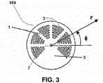
- Fig. 3 Fig. 10 shows a clot trap 100 according to a third embodiment.
- the clot catcher 100 has passage openings 3 in the sieve surface 1, which are located on concentrically arranged partial circles.
- the pitch circles subdivide the sieve surface 1 into segments.
- the passage openings 3 are also arranged in segments.
- the length of the passage openings 3 changes as in FIG Fig. 1 as a function of the radial distance r of the passage openings 3 from a center point 7 of the screen surface 1.
- the length of the passage openings 3 changes in the circumferential direction of the screen surface 1 as a function of the angular orientation ⁇ of the passage openings 3 from a center point 7 of the screen surface 1.
- FIG. 14 shows a front view of the clot trap 100 from FIG Fig. 3 , which is arranged here in a first housing 200.
- a tangential inflow of a fluid is provided — that is, directed toward an edge area or a circumference (which is not to be understood as an end face) of the screen surface 1.
- the fluid flow or the flow or flow direction of the same are indicated here and below by arrows.
- the fluid or the fluid flow enters the clot trap 100 through the inflow area 9 and exits the clot trap 100 at an outflow area 11.
- the fluid usually occurs at the highest point 13 into the clot trap and at the lowest point 15 out of the clot trap 100.
- the location designations “highest” point 13 and “lowest” point 15 preferably relate to an orientation of the clot catcher 100 during its use.
- an inclination of the clot catcher 100 according to the invention during or during its use is - preferably - up to about 15 ° degrees, based on a vertical or perpendicular to the center of the earth or based on the drawing , permitted.
- Figure 5A shows a front view or view from the front of the clot trap 100 according to the invention in a second housing 200.
- the outflow area 11 is in FIG Figure 5A offset to the left to a central axis 17, ie an axis through the center point 7 of the clot catcher.
- the outflow is tangential.
- Figure 5B shows a front view of the clot trap according to the invention in a third housing 200.
- a tangential outflow of the fluid flowing through the clot trap is also provided in the fifth embodiment.
- Fig. 6 shows a sagittal or longitudinal section along S1-S1 Fig. 4 through the center point 7.
- the line S1-S1 corresponds to, as in Fig. 4 shown, the central axis 17 through a center of the clot catcher 1.
- the clot catcher 100 is arranged vertically in the housing 200.
- the section 5 without passage openings is in Fig. 6 below, facing the outflow area 11 or adjacent to it.
- Fig. 7 shows a longitudinal section of the clot trap 100 according to the invention in a housing 200 which is again configured differently.
- the housing 200 has, as in Fig. 7 is shown, gradations or bevels 19 on.
- the clot catcher 100 is provided with a covering device, e.g. a film 21 is provided.
- the film 21 can serve as a coupling surface for a sensor 23 above the clot trap 100.
- the sensor 23 can be a pressure sensor.
- a pressure of a fluid located in the inflow area 9 of the clot catcher 100 can be measured by means of the sensor 23.
- the sensor 23 is connected via a connector 25 to, for example, a treatment device (not shown) or a control or regulating device (not shown) of the same.
- the dashed lines N indicate that the clot catcher 100 according to the invention can be inclined during or during its use by - preferably - up to about 15 degrees, based on a vertical or perpendicular to the center point.
- FIGS 8A to 8C show possible designs of passage openings 3 of the sieve surface 1.
- FIGS. 8A-C show configurations of the passage openings 3 along a section S2-S2 through the screen surface 1 according to FIG Fig. 1 .
- the passage openings 3 are in Figure 8A executed with sharp edges.
- the passage openings 3 are in Figure 8B rounded on one side (in the Figure 5B above).
Landscapes
- Health & Medical Sciences (AREA)
- Heart & Thoracic Surgery (AREA)
- Vascular Medicine (AREA)
- Hematology (AREA)
- Biomedical Technology (AREA)
- Anesthesiology (AREA)
- Engineering & Computer Science (AREA)
- Life Sciences & Earth Sciences (AREA)
- Animal Behavior & Ethology (AREA)
- General Health & Medical Sciences (AREA)
- Public Health (AREA)
- Veterinary Medicine (AREA)
- Cardiology (AREA)
- External Artificial Organs (AREA)
Abstract
Description
- Die vorliegende Erfindung betrifft einen Gerinnselfänger gemäß dem Oberbegriff des Anspruchs 1. Sie betrifft ferner eine externe Funktionseinrichtung gemäß Anspruch 13, einen Blutkreislauf wie hierin offentbart, sowie eine Behandlungsvorrichtung gemäß Anspruch 15.
- Gerinnselfänger werden u.a. in extrakorporalen Blutkreisläufen eingesetzt, um Gerinnsel oder Thromben, welche im extrakorporalen Blutstrom vorliegen, aufzufangen bzw. zurückzuhalten.
- Eine Aufgabe der vorliegenden Erfindung ist, einen weiteren Gerinnselfänger anzugeben.
- Diese Aufgabe wird durch einen Gerinnselfänger mit den Merkmalen des Anspruchs 1 gelöst.
- Der erfindungsgemäße Gerinnselfänger weist eine Siebfläche bzw. eine Gerinnselfängerfläche auf, welche zum Auffangen von Gerinnseln eines die Siebfläche durchströmenden Fluids geeignet und vorgesehen ist.
- Der Begriff "Siebfläche", wie er hierin verwendet wird, bezeichnet eine Einrichtung oder Komponente des Gerinnselfängers, welche ein Durchtreten des Gerinnsels durch den Gerinnselfänger verhindern soll.
- Vorzugsweise ist die Siebfläche eine Einrichtung mit einer mechanisch wirksamen Sieb- bzw. Filterwirkung ohne hierauf beschränkt zu sein.
- Die Siebfläche kann alternativ oder ergänzend ferner dazu geeignet und vorgesehen sein, Gerinnsel beispielsweise auf physikalische und/oder chemische Weise zurückzuhalten oder aufzulösen.
- Die Siebfläche ist erfindungsgemäß scheibenförmig ausgestaltet.
- Der Begriff "scheibenförmig", wie er hierin verwendet wird, bedeutet, dass die Siebfläche - vorzugsweise im Wesentlichen oder vollständig - in Form einer Scheibe ausgestaltet ist.
- Vorteilhafte Weiterentwicklungen der vorliegenden Erfindung sind jeweils Gegenstand der Unteransprüche.
- Im Folgenden gilt: Ein den Gerinnselfänger durchströmendes Fluid tritt - vollständig oder in Teilen hiervon - auf einer Einströmseite in den Gerinnselfänger ein, durchströmt die Siebfläche und tritt auf einer Abströmseite aus dem Gerinnselfänger aus. Unter Gerinnseln sind erfindungsgemäß z.B. Thromben, feste Verunreinigungen und dergleichen zu verstehen.
- Der Begriff "Fluid", wie er hierin verwendet wird, schließt, ohne darauf beschränkt zu sein, Flüssigkeiten, wie medizinische Flüssigkeiten, z.B. Blut, Gase, Emulsionen, Suspensionen, Dispersionen und dergleichen sowie deren Mischungen ein.
- Die Scheibenform der Siebfläche kann in jeder erfindungsgemäßen Ausführungsform uneben und/oder wellig, gekrümmt oder dergleichen sein. Sie kann alternativ eben - im Sinne von flach bzw. in einer Ebene liegend - ausgestaltet sein.
- Die Scheibenform gibt eine Struktur an, welche in einer ersten Dimension (der Haupterstreckung) deutlich größer ist als in einer hierauf senkrechten Richtung.
- Der Gerinnselfänger ist während bzw. zu seiner Verwendung im Wesentlichen senkrecht - vorzugsweise bezogen auf die Haupterstreckung der Siebfläche - angeordnet, wie dies beispielsweise in
Fig. 6 gezeigt ist. - Der Begriff "im Wesentlichen senkrecht", wie er hierin verwendet wird, bedeutet, dass die Neigung des Gerinnselfängers gegen die Vertikale in allen Richtungen maximal etwa 15° betragen darf bzw. eine maximale Neigung von +/- 15° besonders bevorzugt ist. Eine Neigung um weniger als +/- 15° ist ebenfalls bevorzugt. Eine derartige Möglichkeit der Neigung um z. B. 15° im Uhrzeigersinn bzw. um 15° gegen den Uhrzeigersinn oder nach vorne bzw. nach hinten, oder zu einer Seite (also gegen jede Richtung) ist z.T. in den
Fig. 4 und7 angedeutet. - Die Begriffe "senkrecht" bzw. "vertikal" und "waagrecht" bzw. "horizontal" beziehen sich vorzugsweise auf den Erdmittelpunkt.
- Der Gerinnselfänger kann im Gebrauch in einem beliebigen Winkel bzw. in einer beliebigen Schräge, bezogen auf den Erdmittelpunkt, angeordnet sein.
- Eine chemische Filter- bzw. Siebwirkung kann erreicht werden, indem die Gerinnsel chemisch an die Siebfläche und/oder in der Siebfläche, beispielsweise in den Poren derselben, gebunden werden. Die Gerinnsel können reversibel oder irreversibel an die Siebfläche gebunden werden. Die Gerinnsel können physikalisch an der Siebfläche adsorbiert werden. Die Gerinnsel können ferner an der Siebfläche ganz oder teilweise aufgelöst werden.
- In einer bevorzugten Ausführungsform weist die Siebfläche Durchtrittsöffnungen auf, durch welche das Fluid von der Einströmseite zur Abströmseite strömen kann. Mit Hilfe der Durchtrittsöffnungen kann eine mechanische Filter- bzw. Siebwirkung erreicht werden. Die Abmessungen der Durchtrittsöffnungen oder eine Maschenweite der Siebfläche können derart ausgewählt werden, dass die Gerinnsel aufgrund ihrer Größe auf der Einströmseite der einströmenden Fluide zurückgehalten werden.
- Die Durchtrittsöffnungen der Siebfläche bilden zusammen eine offene Gesamtdurchtrittsfläche der Siebfläche.
- Die Abmessungen der Durchtrittsöffnungen können so gewählt sein, dass im strömenden Fluid bzw. Fluidstrom vorhandene Gerinnsel, Agglomerate, Feststoffteilchen und dergleichen aufgrund ihrer Größe auf der Einströmseite des Fluids aus dem Fluidstrom zurückgehalten werden und nicht auf die Abströmseite des Gerinnselfängers gelangen.
- In einer weiteren bevorzugten Ausführungsform sind alle Durchtrittsöffnungen auf - insbesondere konzentrischen - Kreisen oder Kreisabschnitten angeordnet. Eine beispielhafte Anordnung ist nachfolgend in
Fig. 1 gezeigt. - Alternativ dazu ist lediglich eine Vielzahl von Durchtrittsöffnungen auf - insbesondere konzentrischen - Kreisen angeordnet.
- In einer weiter bevorzugten Ausführungsform sind - alle oder nur einige der - Durchtrittsöffnungen radial, bezogen auf einen Mittelpunkt des Gerinnselfängers oder der Siebfläche, angeordnet.
- Der Begriff "Mittelpunkt" bezeichnet einen Mittelpunkt oder einen Punkt in einem mittleren Bereich der scheibenförmigen Siebfläche und/oder des Gerinnselfängers. Dieser Mittelpunkt kann dem Schwerpunkt oder geometrischen Schwerpunkt der Siebfläche und/oder des Gerinnselfängers und/oder einem Kreismittelpunkt einer runden Siebfläche und/oder des Gerinnselfängers entsprechen.
- Im Vergleich zu einer konzentrischen Anordnung der Durchtrittsöffnungen sind die Durchtrittsöffnungen in einer "radialen" Anordnung derart vorgesehen, dass sie sich vom Mittelpunkt der Siebfläche oder des Gerinnselfängers aus in radialer Richtung, insbesondere in einer oder mehreren Ebenen, welche parallel zu einer Haupterstreckungsebene der Siebfläche liegen, erstrecken.
- In einer bevorzugten Ausführungsform ist eine Anzahl von Durchtrittsöffnungen auf der gesamten Siebfläche angeordnet.
- Die Durchtrittsöffnungen können in jeweils gleichem Abstand zueinander über die Siebfläche verteilt angeordnet sein. Die Durchtrittsöffnungen können zueinander versetzt angeordnet sein, wie dies beispielsweise in
Fig. 2 gezeigt ist. - Die Durchtrittsöffnungen können symmetrisch, bezogen auf den Mittelpunkt der Siebfläche und/oder des Gerinnselfängers, auf der Siebfläche angeordnet sein. Sie können jedoch auch asymmetrisch auf der Siebfläche angeordnet sein.
- In einer weiter bevorzugten Ausführungsform weist wenigstens ein Abschnitt der Siebfläche keine - oder verglichen mit anderen Bereichen der Siebfläche eine geringere Anzahl an - Durchtrittsöffnungen auf.
- Ein Beispiel für eine derartige Anordnung ist in
Fig. 3 undFig. 4 gezeigt. - Der Abschnitt ohne - oder mit vergleichsweise nur wenigen - Durchtrittsöffnungen kann dem Abströmbereich des Gerinnselfängers oder eines Gehäuses, in welches der Gerinnselfänger aufgenommen ist, zugewandt sein.
- Dieser Abschnitt kann die Form eines Kreissegments haben. Vorzugsweise liegt der Umfang des Teilkreisbogens stromabwärts zu einer Spitze des Teilkreisbogens in einer Gebrauchsstellung des Gerinnselfängers.
- Die Durchtrittsöffnung(en) kann (können) eine beliebige geeignete geometrische Form aufweisen. Sie können beispielsweise eckig, rund, und/oder elliptisch oder dergleichen ausgestaltet sein.
- Eine Anzahl von Durchtrittsöffnungen kann beispielsweise auf wenigstens einer der beiden Seiten der Siebfläche (Einströmseite und Abströmseite) scharfkantig ausgeführt sein, wie beispielsweise in
Fig. 8A gezeigt ist. - Alternativ oder zusätzlich dazu kann eine Anzahl von Durchtrittsöffnungen auf wenigstens einer Seite der Siebfläche abgerundet oder entgratet ausgeführt sein. Eine beispielhafte Ausführung ist in
Fig. 8B gezeigt. - Die Durchtrittsöffnungen können beidseitig verrundet ausgeführt sein. Eine beispielhafte Ausführung ist in
Fig. 8C gezeigt. - Die Länge und/oder die Breite der Durchtrittsöffnungen kann beispielsweise in Abhängigkeit vom radialen Abstand bzw. von einem Abstand von einem mittleren Bereich ausgehend hin zum Rand der Siebfläche verändert werden. Beispielsweise kann die Länge und/oder die Breite der Durchtrittsöffnungen mit zunehmendem radialen Abstand nach außen hin ebenfalls zunehmen.
- Die Länge und/die Breite der Durchtrittsöffnungen kann beispielsweise in Abhängigkeit von der Winkelorientierung verändert werden.
- Ein "Winkel" kann ein Winkel eines Kreissegments zwischen einer Gerade durch den Mittelpunkt oder eines Punktes eines mittleren Bereichs des Gerinnselfängers oder der Siebfläche und einer anderen Gerade durch den Mittelpunkt der Siebfläche entlang des Kreisbogens des Gerinnselfängers oder der Siebfläche sein.
- Der Gerinnselfänger kann wenigstens abschnittsweise aus einem hämokompatiblen Grundwerkstoff hergestellt sein. Der Gerinnselfänger kann vollständig aus einem hämokompatiblen Grundwerkstoff hergestellt sein.
- Beispiele für geeignete hämokompatible Grundwerkstoffe schließen, ohne darauf beschränkt zu sein, PVP (Polyvinylpyrrolidon), welches vorzugsweise besonders hämokompatibel ist, sowie PP (Polypropylen) ein.
- In einer weiter bevorzugten Ausführungsform ist der Gerinnselfänger aus einem Grundwerkstoff hergestellt. Geeignete Grundwerkstoffe schließen, ohne darauf beschränkt zu sein, Polypropylen, Polyethylen, Polycarbonat, Polyvinylchlorid (PVC), Polyamid (PA) und dergleichen ein.
- Der Grundwerkstoff ist vorzugsweise mit einem oder mehreren hämokompatiblen Werkstoff(en) beschichtet.
- Der Gerinnselfänger kann eine Spritzgusskomponente bzw. ein Spritzgusselement sein.
- Die Siebfläche kann ein Siebgewebe sein. Sie kann im Wesentlichen oder vollständig als Gitterstruktur und/oder Maschenstruktur ausgestaltet sein. Die Siebfläche kann aus Filterpapier, Filtervlies oder dergleichen ausgestaltet oder hergestellt sein.
- Die Siebfläche oder der Gerinnselfänger können durch eine Stützkonstruktion, wie ein Gehäuse, ein Gitter oder dergleichen, gestützt oder getragen werden. Eine Stützkonstruktion kann ebenfalls Sieb- bzw. Filterwirkung haben.
- Beispielsweise kann ein stützendes Gitter an bzw. auf jeder Seite der Siebfläche vorgesehen sein.
- In einer weiter bevorzugten Ausführungsform ist der Gerinnselfänger in einem Gehäuse angeordnet.
- Ein Gehäuse kann zum Schutz des Gerinnselfängers bzw. der Siebfläche und/oder der Befestigung derselben an anderen Strukturen dienen.
- In einer bevorzugten Ausführungsform ist der Gerinnselfänger mit dem Gehäuse verbunden.
- Der Gerinnselfänger kann lösbar mit dem Gehäuse verbunden sein. Er kann beispielsweise mit dem Gehäuse verschnappt oder verrastet oder dergleichen sein.
- Alternativ dazu kann der Gerinnselfänger auch unlösbar mit dem Gehäuse verbunden sein. Er kann beispielsweise mit dem Gehäuse verschweißt oder verklebt oder dergleichen sein.
- Das Verhältnis zwischen offener Gesamtdurchtrittsfläche und Gesamtfläche der Siebfläche oder Gesamtfläche des Gerinnselfängers kann vor Verwendung des Gerinnselfängers der Verwendung des Gerinnselfängers variiert werden.
- Beispielsweise kann das Verhältnis zwischen offener Gesamtdurchtrittsfläche und Gesamtfläche der Siebfläche oder Gesamtfläche des Gerinnselfängers durch Ausgestalteten bzw. Ausformen verschieden bzw. unterschiedlich großer Durchtrittsöffnungen, ggf. mit unterschiedlicher Form, und/oder Ausgestalten bzw. Anordnen oder Vorsehen des Abschnitts ohne Durchtrittsöffnungen bzw. Variieren der Größe und/oder Form desselben variiert werden.
- Der Gerinnselfänger kann derart in ein Gehäuse integriert sein, dass er und/oder seine Siebfläche den Einströmbereich des Gehäuses vom Ausströmbereich trennen.
- In einer weiteren bevorzugten Ausführungsform weist der Gerinnselfänger in wenigstens einem Abschnitt einer Oberseite desselben eine Abdeckungseinrichtung auf.
- Die Abdeckungseinrichtung kann als Ankoppelfläche für wenigstens einen Sensor dienen, wie beispielsweise in
Fig. 7 der beigefügten Zeichnung veranschaulicht ist. Sie kann hierzu vorbereitet sein. Sie kann entsprechende Einrichtungen zum Aufnehmen des Sensors oder eines hiermit bestückten Verbinders aufweisen wie Klemmen, Clipeinrichtungen und/oder dergleichen. - Die erfindungsgemäße Aufgabe wird auch durch eine externe Funktionseinrichtung gemäß Anspruch 13 gelöst. Alle Vorteile des erfindungsgemäßen Gerinnselfängers lassen sich ungeschmälert auch mit der erfindungsgemäßen externen Funktionseinrichtung erreichen.
- Eine erfindungsgemäße externe Funktionseinrichtung weist wenigstens einen erfindungsgemäßen Gerinnselfänger auf.
- Eine "externe Funktionseinrichtung" kann eine Einmalkomponente oder ein Einmalartikel sein. Sie kann aus einem Kunststoffmaterial gefertigt sein.
- Die erfindungsgemäße externe Funktionseinrichtung kann zur Verwendung in einem Behandlungsverfahren angedacht sein. Behandlungsverfahren im Sinne der vorliegenden Erfindung schließen medizinische oder medizintechnische Behandlungsverfahren sowie Behandlungsverfahren der Labortechnik ein.
- In einer bevorzugten Ausführungsform ist die erfindungsgemäße externe Funktionseinrichtung als Blutkassette ausgestaltet.
- Eine Blutkassette, im Sinne der vorliegenden Erfindung ist beispielsweise in der von der Anmelderin der vorliegenden Erfindung in der beim DPMA am 23. April 2009 eingereichten Anmeldung 10 2009 018 664.6 (Vertreterakte FM19A27) und in der am 10. Juni 2009 eingereichten Anmeldung (09/33-d01 DE; FM19A27), jeweils mit dem Titel "Externe Funktionseinrichtung, Blutbehandlungsvorrichtung zum Aufnehmen einer erfindungsgemäßen externen Funktionseinrichtung, sowie Verfahren" beschrieben, auf deren diesbezügliche Offenbarungen hiermit vollinhaltlich Bezug genommen wird.
- Die erfindungsgemäße Aufgabe wird gleichermaßen durch einen erfindungsgemäßen Blutkreislauf wie hierin offenbart gelöst. Alle Vorteile des erfindungsgemäßen Gerinnselfängers lassen sich ungeschmälert auch mit dem erfindungsgemäßen Blutkreislauf erreichen.
- Ein erfindungsgemäßer Blutkreislauf weist wenigstens einen Gerinnselfänger gemäß der Erfindung auf.
- Der Begriff "Blutkreislauf" wie er hierin verwendet wird, bezeichnet ein Schlauchsystem, welches in Form eines extrakorporalen Blutkreislaufs zur Behandlung von Blut geeignet ist.
- Sowohl die externe Funktionseinrichtung als auch der Blutkreislauf können zur Verwendung in oder an einer Behandlungsvorrichtung vorgesehen sein.
- Die erfindungsgemäße Aufgabe wird gleichermaßen durch eine erfindungsgemäße Behandlungsvorrichtung gemäß Anspruch 15 gelöst. Alle Vorteile des erfindungsgemäßen Gerinnselfängers lassen sich ungeschmälert auch mit der erfindungsgemäßen Behandlungsvorrichtung erreichen.
- Eine erfindungsgemäße Behandlungsvorrichtung weist wenigstens einen erfindungsgemäßen Gerinnselfänger und/oder wenigstens eine erfindungsgemäße externe Funktionseinrichtung und/oder wenigstens einen erfindungsgemäßen Blutkreislauf auf.
- Beispielsweise kann die Behandlungsvorrichtung eine Blutbehandlungsvorrichtung, wie eine Dialysiervorrichtung zum Durchführen einer Dialysebehandlung, wie einer Hämodialyse, Hämofiltration, Hämodiafiltration und dergleichen, sein.
- Im Vergleich zu herkömmlichen Gerinnselfängern, in welchen die aktive Siebfläche zylinderförmig oder kegelförmig ausgeführt ist, kann mit der durch den erfindungemäßen Gerinnselfänger erzielbaren Strömungsführung ein Verstopfen des Gerinnselfängers bzw. der Siebfläche desselben vorteilhaft verstärkt verhindert werden.
- Die scheibenförmige Ausgestaltung erlaubt ferner einen platzsparenden Einbau der Siebfläche innerhalb des Gerinnselfängers, gemessen beispielsweise an den eingangs erwähnten herkömmlichen zylinderförmigen Gerinnselfängern.
- Die scheibenförmige Ausgestaltung kann ferner vorteilhafter Weise dazu beitragen, dass etwa eine Blutkassette oder ein Blutschlauch oder dergleichen, in welcher der erfindungsgemäße Gerinnselfänger eingebaut wird, mit geringem Bauraumbedarf realisiert werden kann.
- Insbesondere wenn der erfindungsgemäße Gerinnselfänger mit einem Teilbereich ohne Durchtrittsöffnungen oder mit nur wenigen Durchtrittsöffnungen ausgeführt wird, kann ein Verschließen des Abströmbereichs auf der Rückseite des Gerinnselfängers bei potentiellem Wachstum eines mittels Gerinnselfängers aufgehaltenen Gerinnsels vorteilhaft verlangsamt werden.
- Ferner kann durch Verändern der Länge und Breite der Durchtrittsöffnungen und/oder durch Variieren des Verhältnisses zwischen offener Gesamtdurchtrittsfläche und Gesamtfläche der Siebfläche oder Gesamtfläche des Gerinnselfängers die Durchströmung durch die Durchtrittsöffnungen vorteilhaft so verändert und optimiert werden, dass der Gerinnselfänger optimal durchströmt wird. Dazu kann auch die Gesamtdurchtrittsfläche der Durchtrittsöffnungen vorteilhaft optimiert werden. Eine optimierte Durchströmung kann zu verbesserten Strömungsverhältnissen führen und günstigen Einfluss u.a. auf ein weiteres Gerinnselwachstum am Gerinnselfänger haben.
- Eine Verrundung der Durchtrittsöffnungen kann vorteilhaft dazu beitragen, eine Strömungsablösung der die Durchtrittsöffnungen durchströmenden Fluide wesentlich zu verringern oder zu verhindern.
- Auf diese Weise kann es vorteilhaft möglich sein, eine Hämolyse und/oder eine Gerinnungsaktivierung des Blutes zu reduzieren.
- Das Gehäuse, an welchem der erfindungsgemäße Gerinnselfänger befestigt ist, kann in vorteilhafter Weise so gestaltet sein, dass Luftblasen, die sich auf der Einströmseite des Fluidstroms befinden, aufsteigen können. Die Luftblasen können so vorteilhaft den Einströmbereich des Gerinnselfängers verlassen. Dies ist insbesondere dann vorteilhaft möglich, wenn die Siebfläche des Gerinnselfängers mit ausreichender Steigung gegenüber einer Horizontalen ausgestaltet ist. Sie kann hierzu etwa 45 bis 90 Grad geneigt sein. Vorzugsweise ist sie senkrecht angeordnet.
- Eine senkrechte oder im Wesentlich senkrechte Anordnung der Siebfläche kann ferner in bestimmten Konstruktionen eine Platzeinsparung gegenüber einer horizontalen Anordnung bedeuten. Dies gilt insbesondere, wenn die senkrecht angeordnete Siebfläche parallel oder im Wesentlichen parallel zu einer Abdeckung (wie einer Folie) einer Blutkassette angeordnet ist, in welche sie integriert ist. Als Beispiel einer solchen Blutkassette sein wiederum die oben bereits genannte erwähnt.
- Die Zuströmung zum Gerinnselfänger kann dabei in vorteilhafter Weise so erfolgen, dass die Einströmseite möglichst gut durchspült wird. Beispielsweise kann dies vorteilhaft mit einer möglichst tangentialen Zuströmung erreicht werden.
- "Tangential" kann hierbei ein Anströmen des Gerinnselfängers im Wesentlich in einer Ebene parallel zur Haupterstreckungsebene der Siebfläche bedeuten. Tangential kann wie in den
Fig. 4 ,5A und5B sowie 6 zu erkennen verstanden werden. Gleichermaßen kann, wie in denFig. 5A und5B gezeigt, auch das Abströmen tangential oder seitlich oder in einem Randbereich des Gehäuses oder nicht mittig erfolgen. - Durch Anordnung der Durchtrittsöffnungen auf konzentrischen (Teil-)Kreisen kann zusätzlich vorteilhaft erreicht werden, dass sich eine Rotationsbewegung der Fluide - insbesondere bei tangentialer Ein- bzw. Zuströmung - auch auf der Abströmseite fortsetzt und so die Durchspülung der Abströmseite weiter verbessern kann.
- Der vorliegende Gerinnselfänger kann somit vorteilhaft geeignet sein, der Bildung von Blutgerinnseln - im Sinne der Virchow'schen Trias - auf einfache oder mehrfache Weise entgegen zu wirken.
- Im Folgenden wird die vorliegende Erfindung unter Bezugnahme auf die beigefügte Zeichnung beschrieben. In der Zeichnung bezeichnen identische Bezugszeichen gleiche oder identische Elemente. Es zeigt:
- Fig. 1
- eine Frontansicht bzw. Ansicht von vorne auf den erfindungsgemäßen Gerinnselfänger gemäß einer ersten Ausführungsform;
- Fig. 2
- eine Front- bzw. Vorderansichtansicht auf den Gerinnselfänger gemäß einer zweiten Ausführungsform;
- Fig. 3
- eine Frontansicht auf den erfindungsgemäßen Gerinnselfänger gemäß einer dritten Ausführungsform;
- Fig. 4
- eine Frontansicht auf den Gerinnselfänger der
Fig. 3 , der in einem ersten Gehäuse angeordnet ist; - Fig. 5A
- eine Frontansicht auf den erfindungsgemäßen Gerinnselfänger der
Fig. 2 in einem zweiten Gehäuse; - Fig. 5B
- eine Frontansicht auf den erfindungsgemäßen Gerinnselfänger der
Fig. 2 in einem dritten Gehäuse; - Fig. 6
- einen Längsschnitt des Gerinnselfängers aus
Fig. 4 ; - Fig. 7
- einen Längsschnitt des erfindungsgemäßen Gerinnselfängers, welcher an einen Sensor angekoppelt ist; und
- Fig. 8A-C
- Ausführungen von Durchtrittsöffnungen einer Siebfläche.
-
Fig. 1 zeigt einen erfindungsgemäßen Gerinnselfänger 100 gemäß einer ersten Ausführungsform mit einer Siebfläche 1 in einer Vorder- oder Frontansicht. - In der Siebfläche 1 sind Durchtrittsöffnungen 3 auf konzentrischen Teilkreisen angeordnet.
-
Fig. 2 zeigt den erfindungsgemäßen Gerinnselfänger 100 gemäß einer zweiten Ausführungsform, in dessen Siebfläche 1 die Durchtrittsöffnungen 3 versetzt zueinander auf Kreisen - möglich sind auch Teilkreise - vorgesehen sind. Durch das Versetzen kann eine Überlappung in radialer Richtung entstehen. Dies ist jedoch nicht erforderlich. -
Fig.3 zeigt einen Gerinnselfänger 100 gemäß einer dritten Ausführungsform. - Der Gerinnselfänger 100 weist in der Siebfläche 1 Durchtrittsöffnungen 3 auf, welche auf konzentrisch angeordneten Teilkreisen liegen. Die Teilkreise untergliedern die Siebfläche 1 in Segmente. Die Durchtrittsöffnungen 3 sind ebenfalls in Segmenten angeordnet.
- In einem Abschnitt 5 sind keine Durchtrittsöffnungen vorgesehen.
- Die Länge der Durchtrittsöffnungen 3 ändert sich wie schon in
Fig. 1 in Abhängigkeit vom radialen Abstand r der Durchtrittsöffnungen 3 von einem Mittelpunkt 7 der Siebfläche 1. - Die Länge der Durchtrittsöffnungen 3 ändert sich in Umfangsrichtung der Siebfläche 1 in Abhängigkeit von der Winkelorientierung φ der Durchtrittsöffnungen 3 von einem Mittelpunkt 7 der Siebfläche 1.
-
Fig. 4 zeigt eine Frontansicht auf den Gerinnselfänger 100 ausFig. 3 , welcher hier in einem ersten Gehäuse 200 angeordnet ist. - In einem Einströmbereich 9 des Gehäuses 200 ist ein tangentialer Zustrom - also auf einen Randbereich oder auf einen Umfang (welcher nicht als Stirnseite zu verstehen ist) der Siebfläche 1 gerichtet - eines Fluids vorgesehen. Der Fluidstrom bzw. die Fließ- oder Strömungsrichtung desselben sind hier und im Folgenden durch Pfeile gekennzeichnet.
- Das Fluid bzw. der Fluidstrom tritt durch den Einströmbereich 9 in den Gerinnselfänger 100 ein und tritt an einem Abströmbereich 11 aus dem Gerinnselfänger 100 aus. Das Fluid tritt i.d.R. am höchsten Punkt 13 in den Gerinnselfänger ein und am tiefsten Punkt 15 aus dem Gerinnselfänger 100 aus. Die Lagebezeichnungen "höchster" Punkt 13 und "tiefster" Punkt 15 beziehen sich vorzugsweise auf eine Ausrichtung des Gerinnselfängers 100 während seiner Verwendung.
- Wie mit den gestrichelten Linien N (Neigung) angedeutet ist, ist eine Neigung des erfindungsgemäßen Gerinnselfängers 100 während bzw. zu seiner Verwendung um - vorzugsweise - bis zu etwa 15° Grad, bezogen auf eine Vertikale bzw. Senkrechte zum Erdmittelpunkt oder bezogen auf die Zeichnung, zulässig.
-
Fig. 5A zeigt eine Frontansicht bzw. Ansicht von vorne auf den erfindungsgemäßen Gerinnselfänger 100 in einem zweiten Gehäuse 200. - Im Gegensatz zum ersten Gehäuse 200, wie es z.B. in
Fig. 4 gezeigt ist, ist der Abströmbereich 11 inFig. 5A nach links versetzt zu einer Mittelachse 17, d.h. einer Achse durch den Mittelpunkt 7 des Gerinnselfängers, angeordnet. - Die Abströmung erfolgt tangential.
-
Fig. 5B zeigt eine Frontansicht auf den erfindungsgemäßen Gerinnselfänger in einem dritten Gehäuse 200. - Im Gegensatz zur Darstellung in
Fig. 5A oder inFig. 4 ist der Abströmbereich 11 - bezogen auf die Darstellung inFig. 5B - nach rechts versetzt zu der Mittelachse 17 angeordnet. - Auch in der fünften Ausführungsform ist eine tangentiale Abströmung des den Gerinnselfänger durchströmenden Fluids vorgesehen.
-
Fig. 6 zeigt einen Sagittal- oder Längsschnitt entlang S1-S1 ausFig. 4 durch den Mittelpunkt 7. Die Linie S1-S1 entspricht, wie inFig. 4 gezeigt, der Mittelachse 17 durch ein Zentrum des Gerinnselfängers 1. - Der Gerinnselfänger 100 ist senkrecht im Gehäuse 200 angeordnet.
- Der Abschnitt 5 ohne Durchtrittsöffnungen liegt in
Fig. 6 unten, dem Abströmbereich 11 zugewandt oder diesem benachbart. -
Fig. 7 zeigt einen Längsschnitt des erfindungsgemäßen Gerinnselfängers 100 in einem wiederum unterschiedlich ausgestalteten Gehäuse 200. - Das Gehäuse 200 weist, wie in
Fig. 7 gezeigt ist, Abstufungen bzw. Schrägen 19 auf. - Der Gerinnselfänger 100 ist mit einer Abdeckungseinrichtung, z.B. eine Folie 21 versehen.
- Die Folie 21 kann als Ankoppelfläche für einen Sensor 23 über dem Gerinnselfänger 100 dienen. Der Sensor 23 kann ein Drucksensor sein. Mittels des Sensors 23 kann beispielsweise ein Druck eines im Einströmbereich 9 des Gerinnselfängers 100 befindlichen Fluids gemessen werden.
- Der Sensor 23 ist über einen Konnektor oder Verbinder 25 mit beispielsweise einer Behandlungsvorrichtung (nicht gezeigt) bzw. einer Steuer- oder Regeleinrichtung (nicht gezeigt) derselben verbunden.
- Auch in
Fig. 7 deuten die gestrichelten Linien N (Neigung) an, dass der erfindungsgemäße Gerinnselfänger 100 während bzw. zu seiner Verwendung um - vorzugsweise - bis zu etwa 15° Grad, bezogen auf eine Vertikale bzw. Senkrechte zum Mittelpunkt, geneigt sein kann. - Die
Fig. 8A bis 8C zeigen mögliche Ausführungen von Durchtrittsöffnungen 3 der Siebfläche 1. - Die
Fig. 8A-C zeigen Ausgestaltungen der Durchtrittsöffnungen 3 entlang eines Schnitts S2-S2 durch die Siebfläche 1 gemäßFig. 1 . - Die Durchtrittsöffnungen 3 sind in
Fig. 8A scharfkantig ausgeführt. - Die Durchtrittsöffnungen 3 sind in
Fig. 8B einseitig verrundet (in derFig. 5B oben) ausgeführt. - In
Fig. 8C sind die Durchtrittsöffnungen 3 beidseitig verrundet ausgeführt.
Claims (15)
- Gerinnselfänger (100) mit einer Siebfläche (1) zum Auffangen von Gerinnseln in einem die Siebfläche (1) durchströmenden Fluid, wobei die Siebfläche (1) Durchtrittsöffnungen (3) aufweist, durch welche das Fluid strömen kann,
dadurch gekennzeichnet, dass
die Siebfläche (1) scheibenförmig ausgestaltet ist, und dass
ein Abschnitt (5) der Siebfläche (1) keine Durchtrittöffnungen (3) aufweist. - Gerinnselfänger (100) nach Anspruch 1, wobei eine Anzahl der Durchtrittsöffnungen (3) auf konzentrischen Kreisen oder Teilkreisen angeordnet sind.
- Gerinnselfänger (100) nach einem der vorangegangenen Ansprüche, wobei eine Anzahl der Durchtrittsöffnungen (3) radial, bezogen auf einen Mittelpunkt (7) des Gerinnselfängers (100) oder der Siebfläche (1), angeordnet sind.
- Gerinnselfänger (100) nach einem der vorangegangenen Ansprüche, wobei der Abschnitt (5) einem Abströmbereich (11) des Gerinnselfängers (100) oder eines Gehäuses (200), in welches der Gerinnselfänger (100) aufgenommen ist, zugewandt ist.
- Gerinnselfänger (100) nach einem der einem der vorangegangenen Ansprüche, wobei eine Anzahl von Durchtrittsöffnungen (3) auf einer der beiden Seiten der Siebfläche (1) scharfkantig ausgeführt ist.
- Gerinnselfänger (100) nach einem der vorangegangenen Ansprüche, wobei eine Anzahl von Durchtrittsöffnungen (3) auf einer Seite der Siebfläche (1) abgerundet ausgeführt sind.
- Gerinnselfänger (100) nach einem der vorangegangenen Ansprüche, wobei die Durchtrittsöffnungen (3) beidseitig verrundet ausgeführt sind.
- Gerinnselfänger (100) nach einem der vorangegangenen Ansprüche, angeordnet in einem Gehäuse (200).
- Gerinnselfänger (100) nach Anspruch 8, wobei der Gerinnselfänger (100) mit dem Gehäuse (200) verschnappt ist.
- Gerinnselfänger (100) nach Anspruch 8, wobei der Gerinnselfänger (100) mit dem Gehäuse (200) verschweißt ist.
- Gerinnselfänger (100) nach einem der vorangegangenen Ansprüche, welcher in wenigstens einem Abschnitt einer Oberseite desselben eine Abdeckungseinrichtung aufweist.
- Gerinnselfänger (100) nach Anspruch 11, wobei die Abdeckungseinrichtung als Ankoppelfläche für wenigstens einen Sensor (23) dient.
- Externe Funktionseinrichtung, welche einen Gerinnselfänger (100) gemäß einem der Ansprüche 1 bis 12 aufweist.
- Externe Funktionseinrichtung, wobei die externe Funktionseinrichtung eine Blutkassette ist.
- Behandlungsvorrichtung, welche einen Gerinnselfänger (100) gemäß einem der Ansprüche 1 bis 12 und/oder eine externe Funktionseinrichtung gemäß Anspruch 13 oder 14 aufweist, wobei die Behandlungsvorrichtung als Blutbehandlungsvorrichtung ausgestaltet ist.
Applications Claiming Priority (5)
| Application Number | Priority Date | Filing Date | Title |
|---|---|---|---|
| DE102009018664A DE102009018664A1 (de) | 2009-04-23 | 2009-04-23 | Externe Funktionseinrichtung, Blutbehandlungsvorrichtung zum Aufnehmen einer erfindungsgemäßen externen Funktionseinrichtung, sowie Verfahren |
| US18562309P | 2009-06-10 | 2009-06-10 | |
| DE102009024495A DE102009024495A1 (de) | 2009-06-10 | 2009-06-10 | Gerinnselfänger, externe Funktionseinrichtung, Blutkreislauf sowie Behandlungsvorrichtung |
| PCT/EP2010/002297 WO2010121743A1 (de) | 2009-04-23 | 2010-04-14 | Gerinnselfänger, externe funktionseinrichtung, blutkreislauf sowie behandlungsvorrichtung |
| EP10714197.0A EP2421574B1 (de) | 2009-04-23 | 2010-04-14 | Gerinnselfänger, externe funktionseinrichtung, blutkreislauf sowie behandlungsvorrichtung |
Related Parent Applications (1)
| Application Number | Title | Priority Date | Filing Date |
|---|---|---|---|
| EP10714197.0A Division EP2421574B1 (de) | 2009-04-23 | 2010-04-14 | Gerinnselfänger, externe funktionseinrichtung, blutkreislauf sowie behandlungsvorrichtung |
Publications (2)
| Publication Number | Publication Date |
|---|---|
| EP3708201A1 true EP3708201A1 (de) | 2020-09-16 |
| EP3708201B1 EP3708201B1 (de) | 2025-06-18 |
Family
ID=42991184
Family Applications (2)
| Application Number | Title | Priority Date | Filing Date |
|---|---|---|---|
| EP20164806.0A Active EP3708201B1 (de) | 2009-04-23 | 2010-04-14 | Gerinnselfaenger, externe funktionseinrichtung, blutkreislauf sowie behandlungsvorrichtung |
| EP10714197.0A Active EP2421574B1 (de) | 2009-04-23 | 2010-04-14 | Gerinnselfänger, externe funktionseinrichtung, blutkreislauf sowie behandlungsvorrichtung |
Family Applications After (1)
| Application Number | Title | Priority Date | Filing Date |
|---|---|---|---|
| EP10714197.0A Active EP2421574B1 (de) | 2009-04-23 | 2010-04-14 | Gerinnselfänger, externe funktionseinrichtung, blutkreislauf sowie behandlungsvorrichtung |
Country Status (5)
| Country | Link |
|---|---|
| US (1) | US9421328B2 (de) |
| EP (2) | EP3708201B1 (de) |
| JP (1) | JP5713212B2 (de) |
| CN (2) | CN102405069B (de) |
| WO (1) | WO2010121743A1 (de) |
Families Citing this family (21)
| Publication number | Priority date | Publication date | Assignee | Title |
|---|---|---|---|---|
| DE102011110472A1 (de) * | 2011-07-29 | 2013-01-31 | Fresenius Medical Care Deutschland Gmbh | Verfahren sowie Vorrichtungen zum Ablösen von Gasansammlungen von einem Gerinnselfänger eines extrakorporalen Blutkreislaufs |
| DE102013106582A1 (de) * | 2013-06-24 | 2014-12-24 | Ulrich Gmbh & Co. Kg | Druckmesszelle zur Verwendung in einem Infusions- oder Injektionssystem |
| DE102014002578A1 (de) | 2014-02-26 | 2015-08-27 | Fresenius Medical Care Deutschland Gmbh | Medizinische Flüssigkeitskassette und medizinischer Schlauchsatz mit medizinischer Flüssigkeitskassette |
| CN108135591B (zh) | 2016-02-24 | 2021-05-28 | 禾木(中国)生物工程有限公司 | 柔性增强的神经血管导管 |
| EP3246052A1 (de) | 2016-05-20 | 2017-11-22 | Fresenius Medical Care | Röhrenverbindung |
| JP7053630B2 (ja) | 2016-09-22 | 2022-04-12 | クリストファー, ジェイ プロット, | 血液の体外コンディショニングのための機器及び方法 |
| JP7264581B2 (ja) | 2017-01-06 | 2023-04-25 | インセプト、リミテッド、ライアビリティ、カンパニー | 動脈瘤治療装置向けの抗血栓性コーティング |
| DE102017005535A1 (de) * | 2017-06-10 | 2018-12-13 | Fresenius Medical Care Deutschland Gmbh | Vorrichtung zur extrakorporalen Blutbehandlung und Vorrichtung zum Sammeln von Blutgerinnseln sowie Verfahren zum Bestimmen eines hämodynamischen Parameters während einer extrakorporalen Blutbehandlung |
| CN119405388A (zh) | 2018-05-01 | 2025-02-11 | 因赛普特有限责任公司 | 用于从血管内部位去除闭塞性物质的装置和方法 |
| US11395665B2 (en) | 2018-05-01 | 2022-07-26 | Incept, Llc | Devices and methods for removing obstructive material, from an intravascular site |
| US11471582B2 (en) | 2018-07-06 | 2022-10-18 | Incept, Llc | Vacuum transfer tool for extendable catheter |
| US11517335B2 (en) | 2018-07-06 | 2022-12-06 | Incept, Llc | Sealed neurovascular extendable catheter |
| EP4044906B1 (de) | 2019-10-15 | 2025-03-12 | Kandu Health, Inc. | Systeme und verfahren zur mehrgrössenhubdetektion |
| US11633272B2 (en) | 2019-12-18 | 2023-04-25 | Imperative Care, Inc. | Manually rotatable thrombus engagement tool |
| JP2023507553A (ja) | 2019-12-18 | 2023-02-24 | インパラティブ、ケア、インク. | 静脈血栓塞栓症を治療するための方法及びシステム |
| US11457936B2 (en) | 2019-12-18 | 2022-10-04 | Imperative Care, Inc. | Catheter system for treating thromboembolic disease |
| WO2021183444A1 (en) | 2020-03-10 | 2021-09-16 | Imperative Care, Inc. | Enhanced flexibility neurovascular catheter |
| US11207497B1 (en) | 2020-08-11 | 2021-12-28 | Imperative Care, Inc. | Catheter with enhanced tensile strength |
| US12558175B2 (en) | 2021-08-12 | 2026-02-24 | Imperative Care, Inc. | Multi catheter method of performing a robotic neurovascular procedure |
| USD1077996S1 (en) | 2021-10-18 | 2025-06-03 | Imperative Care, Inc. | Inline fluid filter |
| DE102022128054A1 (de) * | 2022-10-24 | 2024-04-25 | ThrombShield UG (haftungsbeschränkt) | Vorrichtung zur extrakorporalen Filterung von Blut, Verfahren zur Durchführung einer extrakorporalen Membranoxygenierung, Verwendung einer Vorrichtung zur extrakorporalen Filterung und System für die extrakorporale Membranoxygenierung |
Citations (5)
| Publication number | Priority date | Publication date | Assignee | Title |
|---|---|---|---|---|
| DE4404277A1 (de) * | 1994-02-10 | 1995-08-17 | Roland Wex | Blutfilter |
| DE29706807U1 (de) * | 1997-04-16 | 1997-06-19 | Schneider, Lothar, 77866 Rheinau | Vorfilter für eine Vorrichtung zum Sammeln und groben Reinigen von bei Operationen anfallendem Blut |
| US6468225B1 (en) * | 1994-09-20 | 2002-10-22 | Astra Tech Ab | Method and apparatus for collecting bone tissue fragments |
| US20050139532A1 (en) * | 2003-10-20 | 2005-06-30 | David Hershberger | Manifold assembly |
| WO2008065472A1 (en) * | 2006-12-01 | 2008-06-05 | Gambro Lundia Ab | A blood transfer chamber |
Family Cites Families (31)
| Publication number | Priority date | Publication date | Assignee | Title |
|---|---|---|---|---|
| US4177149A (en) * | 1978-07-21 | 1979-12-04 | Pall Corporation | Filter assembly for intravenous liquid administration apparatus |
| JPS55133256A (en) * | 1979-04-03 | 1980-10-16 | Terumo Corp | Filter |
| IL64001A0 (en) | 1981-10-06 | 1982-01-31 | Elmar Medical Systems Ltd | Blood treatment system |
| JPS61247464A (ja) * | 1985-04-25 | 1986-11-04 | テルモ株式会社 | 血液用濾材およびその製造方法 |
| US4806135A (en) | 1988-03-01 | 1989-02-21 | Siposs George G | Bubble trap for phase-separating gas bubbles from flowing liquids |
| DE68902698C5 (de) * | 1988-06-23 | 2005-07-14 | Asahi Medical Co. Ltd. | Verfahren zur Trennung von Blut in Blutkomponenten und Einheit zur Trennung von Blutkomponenten. |
| IT1231024B (it) | 1989-07-31 | 1991-11-08 | Dideco Spa | Contenitore di sangue per apparecchio medicale |
| US5298016A (en) * | 1992-03-02 | 1994-03-29 | Advanced Haemotechnologies | Apparatus for separating plasma and other wastes from blood |
| SE470377B (sv) * | 1993-02-11 | 1994-02-07 | Gambro Dialysatoren | Dropp- och/eller expansionskammare med inbyggt filter och förfarande för framställning av en sådan |
| EP0684866B1 (de) * | 1993-12-22 | 1999-03-31 | Baxter International Inc. | Verfahren zur schätzung des durchschnittlichen faserdurchmessers von unterschiedlichen filtrationsmitteln |
| US5798041A (en) * | 1995-09-06 | 1998-08-25 | Hemasure, Inc. | In-line liquid filtration device useable for blood, blood products or the like |
| US5591344A (en) * | 1995-02-13 | 1997-01-07 | Aksys, Ltd. | Hot water disinfection of dialysis machines, including the extracorporeal circuit thereof |
| DE59603763D1 (de) | 1995-08-16 | 2000-01-05 | Friadent Gmbh | Sammelvorrichtung |
| DE69732249T2 (de) | 1996-11-22 | 2005-12-08 | Therakos, Inc. | Kassette zum steuern und pumpen von fluiden |
| US6468427B1 (en) | 1998-09-29 | 2002-10-22 | Gambro, Inc. | Fluid filter for use in extracorporeal blood processing |
| WO2000023140A1 (en) * | 1998-10-16 | 2000-04-27 | Mission Medical, Inc. | Blood processing system |
| US6458278B1 (en) * | 1999-02-22 | 2002-10-01 | Nalge Nunc International Corporation | Filtering unit having separately attachable filter cassette, filter cassette, and method of filtering |
| JP4090628B2 (ja) | 1999-07-01 | 2008-05-28 | 株式会社パイオラックス | 流体フィルタ |
| US6723062B1 (en) * | 1999-09-03 | 2004-04-20 | Baxter International Inc. | Fluid pressure actuated blood pumping systems and methods with continuous inflow and pulsatile outflow conditions |
| US6663613B1 (en) * | 2000-01-25 | 2003-12-16 | Bacchus Vascular, Inc. | System and methods for clot dissolution |
| US7713227B2 (en) * | 2000-03-20 | 2010-05-11 | Michael Wholey | Method and apparatus for medical device for aspiration of thromboemobolic debris |
| US20050021075A1 (en) * | 2002-12-30 | 2005-01-27 | Bonnette Michael J. | Guidewire having deployable sheathless protective filter |
| US20040127840A1 (en) | 2002-03-04 | 2004-07-01 | Steve Gara | Blood separation apparatus and method of using the same |
| JP4083550B2 (ja) * | 2002-11-26 | 2008-04-30 | 川澄化学工業株式会社 | 血液成分分離装置及び血液成分分離方法 |
| DE10304365A1 (de) | 2003-02-04 | 2004-08-05 | Ls-Medcap Gmbh | Filtervorrichtung |
| US7722577B2 (en) * | 2005-02-18 | 2010-05-25 | Becton, Dickinson And Company | Bubble free—self primed IV set |
| US7781226B2 (en) * | 2004-02-27 | 2010-08-24 | The Board Of Regents Of The University Of Texas System | Particle on membrane assay system |
| JP2006280483A (ja) * | 2005-03-31 | 2006-10-19 | Terumo Corp | 血液処理フィルター |
| DE102007042964A1 (de) | 2007-09-10 | 2009-03-19 | Fresenius Medical Care Deutschland Gmbh | Vorrichtung und Verfahren zur Behandlung einer medizinischen Flüssigkeit und medizinische Kassette |
| DE102009018664A1 (de) | 2009-04-23 | 2010-10-28 | Fresenius Medical Care Deutschland Gmbh | Externe Funktionseinrichtung, Blutbehandlungsvorrichtung zum Aufnehmen einer erfindungsgemäßen externen Funktionseinrichtung, sowie Verfahren |
| DE102009024468A1 (de) | 2009-06-10 | 2010-12-16 | Fresenius Medical Care Deutschland Gmbh | Externe Funktionseinrichtung, Blutbehandlungsvorrichtung zum Aufnehmen einer erfindungsgemäßen externen Funktionseinrichtung, sowie Verfahren |
-
2010
- 2010-04-14 WO PCT/EP2010/002297 patent/WO2010121743A1/de not_active Ceased
- 2010-04-14 EP EP20164806.0A patent/EP3708201B1/de active Active
- 2010-04-14 CN CN201080017594.7A patent/CN102405069B/zh active Active
- 2010-04-14 JP JP2012506377A patent/JP5713212B2/ja active Active
- 2010-04-14 EP EP10714197.0A patent/EP2421574B1/de active Active
- 2010-04-14 CN CN201510595040.XA patent/CN105169510B/zh active Active
- 2010-04-22 US US12/765,154 patent/US9421328B2/en active Active
Patent Citations (5)
| Publication number | Priority date | Publication date | Assignee | Title |
|---|---|---|---|---|
| DE4404277A1 (de) * | 1994-02-10 | 1995-08-17 | Roland Wex | Blutfilter |
| US6468225B1 (en) * | 1994-09-20 | 2002-10-22 | Astra Tech Ab | Method and apparatus for collecting bone tissue fragments |
| DE29706807U1 (de) * | 1997-04-16 | 1997-06-19 | Schneider, Lothar, 77866 Rheinau | Vorfilter für eine Vorrichtung zum Sammeln und groben Reinigen von bei Operationen anfallendem Blut |
| US20050139532A1 (en) * | 2003-10-20 | 2005-06-30 | David Hershberger | Manifold assembly |
| WO2008065472A1 (en) * | 2006-12-01 | 2008-06-05 | Gambro Lundia Ab | A blood transfer chamber |
Also Published As
| Publication number | Publication date |
|---|---|
| JP5713212B2 (ja) | 2015-05-07 |
| CN105169510B (zh) | 2018-09-21 |
| US9421328B2 (en) | 2016-08-23 |
| EP2421574B1 (de) | 2020-03-25 |
| EP2421574A1 (de) | 2012-02-29 |
| US20100270230A1 (en) | 2010-10-28 |
| CN102405069A (zh) | 2012-04-04 |
| EP3708201B1 (de) | 2025-06-18 |
| CN102405069B (zh) | 2015-09-16 |
| WO2010121743A1 (de) | 2010-10-28 |
| CN105169510A (zh) | 2015-12-23 |
| JP2012524560A (ja) | 2012-10-18 |
Similar Documents
| Publication | Publication Date | Title |
|---|---|---|
| EP3708201B1 (de) | Gerinnselfaenger, externe funktionseinrichtung, blutkreislauf sowie behandlungsvorrichtung | |
| DE102009024495A1 (de) | Gerinnselfänger, externe Funktionseinrichtung, Blutkreislauf sowie Behandlungsvorrichtung | |
| EP0079553B1 (de) | Mikrofiltrationsgerät zur Filtration von Koageln und Mikroaggregaten von Blut | |
| DE69927105T2 (de) | Gefilterte Zugangsöffnung mit Filterbypass zum Zugriff auf Körperflüssigkeitsproben | |
| DE3877852T2 (de) | Selbsttaetig arbeitender filter. | |
| EP2421584B1 (de) | Luftabscheider, externe funktionseinrichtung, blutkreislauf sowie behandlungsvorrichtung | |
| DE60035560T2 (de) | Filtrationseinheit für eine viruzide Substanz | |
| EP3563890A1 (de) | Organizer zum lösbaren aufnehmen von komponenten von blutschlauchsätzen und verfahren zum herstellen sowie zum vorbereiten desselben | |
| DE2637908B2 (de) | Nadelhalter für eine medizinische Verabreichungsvorrichtung mit einer Filteranordnung | |
| DE2329760A1 (de) | Kaskade von blutfiltern | |
| EP2421583B1 (de) | Einrichtung sowie externe funktionseinrichtung und behandlungsvorrichtung zum behandeln von medizinischen fluiden | |
| DE3020449A1 (de) | Filtervorrichtung fuer eine intravenoes- infusionsanlage | |
| DE102005011740B4 (de) | Venöse Blasenfalle | |
| DE2926434C2 (de) | In einem Rohr angeordnete Filtereinrichtung für eine medizinische Infusionsvorrichtung | |
| EP4331711A1 (de) | Einweg-filtercapsule fur eine filtrationsvorrichtung | |
| DE3248891C2 (de) | Luftfilter | |
| EP2749335B1 (de) | Zweiteiliger Partikelfilter | |
| EP4272852B1 (de) | Filtermodul für einen rotationsscheibenfilter sowie rotationsscheibenfilter | |
| DE3202330A1 (de) | Im wesentlichen symmetrisch aufgebautes zweiteiligesfiltergehaeuse aus kunststoff | |
| DD235371A1 (de) | Vorrichtung zur ueberfuehrung einer fluessigkeit | |
| EP4333934B1 (de) | Infusionsfilter, und infusionsset mit infusionsfilter | |
| EP3600494B1 (de) | Haltevorrichtung für medizinische behandlungsvorrichtungen | |
| DE3828672C1 (de) | ||
| WO2025252709A1 (de) | Gerinnselfänger mit siebfläche und sich hiervon erhebender struktur | |
| EP3290068B1 (de) | Kartuschenförmiger behälter mit einer siebartigen filtereinrichtung |
Legal Events
| Date | Code | Title | Description |
|---|---|---|---|
| PUAI | Public reference made under article 153(3) epc to a published international application that has entered the european phase |
Free format text: ORIGINAL CODE: 0009012 |
|
| STAA | Information on the status of an ep patent application or granted ep patent |
Free format text: STATUS: THE APPLICATION HAS BEEN PUBLISHED |
|
| AC | Divisional application: reference to earlier application |
Ref document number: 2421574 Country of ref document: EP Kind code of ref document: P |
|
| AK | Designated contracting states |
Kind code of ref document: A1 Designated state(s): AT BE BG CH CY CZ DE DK EE ES FI FR GB GR HR HU IE IS IT LI LT LU LV MC MK MT NL NO PL PT RO SE SI SK SM TR |
|
| RIN1 | Information on inventor provided before grant (corrected) |
Inventor name: BRUECKNER, CHRISTOPH Inventor name: WEIS, MANFRED Inventor name: LAUER, MARTIN |
|
| STAA | Information on the status of an ep patent application or granted ep patent |
Free format text: STATUS: REQUEST FOR EXAMINATION WAS MADE |
|
| 17P | Request for examination filed |
Effective date: 20210312 |
|
| RBV | Designated contracting states (corrected) |
Designated state(s): AT BE BG CH CY CZ DE DK EE ES FI FR GB GR HR HU IE IS IT LI LT LU LV MC MK MT NL NO PL PT RO SE SI SK SM TR |
|
| GRAP | Despatch of communication of intention to grant a patent |
Free format text: ORIGINAL CODE: EPIDOSNIGR1 |
|
| STAA | Information on the status of an ep patent application or granted ep patent |
Free format text: STATUS: GRANT OF PATENT IS INTENDED |
|
| INTG | Intention to grant announced |
Effective date: 20240726 |
|
| GRAS | Grant fee paid |
Free format text: ORIGINAL CODE: EPIDOSNIGR3 |
|
| GRAJ | Information related to disapproval of communication of intention to grant by the applicant or resumption of examination proceedings by the epo deleted |
Free format text: ORIGINAL CODE: EPIDOSDIGR1 |
|
| GRAL | Information related to payment of fee for publishing/printing deleted |
Free format text: ORIGINAL CODE: EPIDOSDIGR3 |
|
| STAA | Information on the status of an ep patent application or granted ep patent |
Free format text: STATUS: REQUEST FOR EXAMINATION WAS MADE |
|
| INTC | Intention to grant announced (deleted) | ||
| GRAP | Despatch of communication of intention to grant a patent |
Free format text: ORIGINAL CODE: EPIDOSNIGR1 |
|
| STAA | Information on the status of an ep patent application or granted ep patent |
Free format text: STATUS: GRANT OF PATENT IS INTENDED |
|
| INTG | Intention to grant announced |
Effective date: 20250116 |
|
| P01 | Opt-out of the competence of the unified patent court (upc) registered |
Free format text: CASE NUMBER: APP_10395/2025 Effective date: 20250303 |
|
| GRAA | (expected) grant |
Free format text: ORIGINAL CODE: 0009210 |
|
| STAA | Information on the status of an ep patent application or granted ep patent |
Free format text: STATUS: THE PATENT HAS BEEN GRANTED |
|
| AC | Divisional application: reference to earlier application |
Ref document number: 2421574 Country of ref document: EP Kind code of ref document: P |
|
| AK | Designated contracting states |
Kind code of ref document: B1 Designated state(s): AT BE BG CH CY CZ DE DK EE ES FI FR GB GR HR HU IE IS IT LI LT LU LV MC MK MT NL NO PL PT RO SE SI SK SM TR |
|
| REG | Reference to a national code |
Ref country code: GB Ref legal event code: FG4D Free format text: NOT ENGLISH |
|
| REG | Reference to a national code |
Ref country code: CH Ref legal event code: EP |
|
| REG | Reference to a national code |
Ref country code: DE Ref legal event code: R096 Ref document number: 502010017111 Country of ref document: DE |
|
| REG | Reference to a national code |
Ref country code: CH Ref legal event code: EP |
|
| REG | Reference to a national code |
Ref country code: IE Ref legal event code: FG4D Free format text: LANGUAGE OF EP DOCUMENT: GERMAN |
|
| PG25 | Lapsed in a contracting state [announced via postgrant information from national office to epo] |
Ref country code: FI Free format text: LAPSE BECAUSE OF FAILURE TO SUBMIT A TRANSLATION OF THE DESCRIPTION OR TO PAY THE FEE WITHIN THE PRESCRIBED TIME-LIMIT Effective date: 20250618 |
|
| REG | Reference to a national code |
Ref country code: LT Ref legal event code: MG9D |
|
| PG25 | Lapsed in a contracting state [announced via postgrant information from national office to epo] |
Ref country code: GR Free format text: LAPSE BECAUSE OF FAILURE TO SUBMIT A TRANSLATION OF THE DESCRIPTION OR TO PAY THE FEE WITHIN THE PRESCRIBED TIME-LIMIT Effective date: 20250919 Ref country code: NO Free format text: LAPSE BECAUSE OF FAILURE TO SUBMIT A TRANSLATION OF THE DESCRIPTION OR TO PAY THE FEE WITHIN THE PRESCRIBED TIME-LIMIT Effective date: 20250918 |
|
| PG25 | Lapsed in a contracting state [announced via postgrant information from national office to epo] |
Ref country code: BG Free format text: LAPSE BECAUSE OF FAILURE TO SUBMIT A TRANSLATION OF THE DESCRIPTION OR TO PAY THE FEE WITHIN THE PRESCRIBED TIME-LIMIT Effective date: 20250618 |
|
| PG25 | Lapsed in a contracting state [announced via postgrant information from national office to epo] |
Ref country code: HR Free format text: LAPSE BECAUSE OF FAILURE TO SUBMIT A TRANSLATION OF THE DESCRIPTION OR TO PAY THE FEE WITHIN THE PRESCRIBED TIME-LIMIT Effective date: 20250618 |
|
| REG | Reference to a national code |
Ref country code: NL Ref legal event code: MP Effective date: 20250618 |
|
| PG25 | Lapsed in a contracting state [announced via postgrant information from national office to epo] |
Ref country code: LV Free format text: LAPSE BECAUSE OF FAILURE TO SUBMIT A TRANSLATION OF THE DESCRIPTION OR TO PAY THE FEE WITHIN THE PRESCRIBED TIME-LIMIT Effective date: 20250618 |
|
| PG25 | Lapsed in a contracting state [announced via postgrant information from national office to epo] |
Ref country code: NL Free format text: LAPSE BECAUSE OF FAILURE TO SUBMIT A TRANSLATION OF THE DESCRIPTION OR TO PAY THE FEE WITHIN THE PRESCRIBED TIME-LIMIT Effective date: 20250618 |
|
| PG25 | Lapsed in a contracting state [announced via postgrant information from national office to epo] |
Ref country code: PT Free format text: LAPSE BECAUSE OF FAILURE TO SUBMIT A TRANSLATION OF THE DESCRIPTION OR TO PAY THE FEE WITHIN THE PRESCRIBED TIME-LIMIT Effective date: 20251020 |
|
| REG | Reference to a national code |
Ref country code: CH Ref legal event code: W10 Free format text: ST27 STATUS EVENT CODE: U-0-0-W10-W00 (AS PROVIDED BY THE NATIONAL OFFICE) Effective date: 20251224 |
|
| PG25 | Lapsed in a contracting state [announced via postgrant information from national office to epo] |
Ref country code: IS Free format text: LAPSE BECAUSE OF FAILURE TO SUBMIT A TRANSLATION OF THE DESCRIPTION OR TO PAY THE FEE WITHIN THE PRESCRIBED TIME-LIMIT Effective date: 20251018 |
|
| PG25 | Lapsed in a contracting state [announced via postgrant information from national office to epo] |
Ref country code: SM Free format text: LAPSE BECAUSE OF FAILURE TO SUBMIT A TRANSLATION OF THE DESCRIPTION OR TO PAY THE FEE WITHIN THE PRESCRIBED TIME-LIMIT Effective date: 20250618 |
|
| PG25 | Lapsed in a contracting state [announced via postgrant information from national office to epo] |
Ref country code: CZ Free format text: LAPSE BECAUSE OF FAILURE TO SUBMIT A TRANSLATION OF THE DESCRIPTION OR TO PAY THE FEE WITHIN THE PRESCRIBED TIME-LIMIT Effective date: 20250618 |
|
| RAP4 | Party data changed (patent owner data changed or rights of a patent transferred) |
Owner name: FRESENIUS MEDICAL CARE DEUTSCHLAND GMBH |
|
| PG25 | Lapsed in a contracting state [announced via postgrant information from national office to epo] |
Ref country code: PL Free format text: LAPSE BECAUSE OF FAILURE TO SUBMIT A TRANSLATION OF THE DESCRIPTION OR TO PAY THE FEE WITHIN THE PRESCRIBED TIME-LIMIT Effective date: 20250618 |
|
| PG25 | Lapsed in a contracting state [announced via postgrant information from national office to epo] |
Ref country code: EE Free format text: LAPSE BECAUSE OF FAILURE TO SUBMIT A TRANSLATION OF THE DESCRIPTION OR TO PAY THE FEE WITHIN THE PRESCRIBED TIME-LIMIT Effective date: 20250618 |
|
| PG25 | Lapsed in a contracting state [announced via postgrant information from national office to epo] |
Ref country code: SK Free format text: LAPSE BECAUSE OF FAILURE TO SUBMIT A TRANSLATION OF THE DESCRIPTION OR TO PAY THE FEE WITHIN THE PRESCRIBED TIME-LIMIT Effective date: 20250618 Ref country code: RO Free format text: LAPSE BECAUSE OF FAILURE TO SUBMIT A TRANSLATION OF THE DESCRIPTION OR TO PAY THE FEE WITHIN THE PRESCRIBED TIME-LIMIT Effective date: 20250618 |
|
| PG25 | Lapsed in a contracting state [announced via postgrant information from national office to epo] |
Ref country code: ES Free format text: LAPSE BECAUSE OF FAILURE TO SUBMIT A TRANSLATION OF THE DESCRIPTION OR TO PAY THE FEE WITHIN THE PRESCRIBED TIME-LIMIT Effective date: 20250618 |
|
| REG | Reference to a national code |
Ref country code: DE Ref legal event code: R097 Ref document number: 502010017111 Country of ref document: DE |
|
| PGFP | Annual fee paid to national office [announced via postgrant information from national office to epo] |
Ref country code: GB Payment date: 20260319 Year of fee payment: 17 |
|
| PG25 | Lapsed in a contracting state [announced via postgrant information from national office to epo] |
Ref country code: DK Free format text: LAPSE BECAUSE OF FAILURE TO SUBMIT A TRANSLATION OF THE DESCRIPTION OR TO PAY THE FEE WITHIN THE PRESCRIBED TIME-LIMIT Effective date: 20250618 |
|
| PG25 | Lapsed in a contracting state [announced via postgrant information from national office to epo] |
Ref country code: IT Free format text: LAPSE BECAUSE OF FAILURE TO SUBMIT A TRANSLATION OF THE DESCRIPTION OR TO PAY THE FEE WITHIN THE PRESCRIBED TIME-LIMIT Effective date: 20250618 |
|
| PGFP | Annual fee paid to national office [announced via postgrant information from national office to epo] |
Ref country code: FR Payment date: 20260319 Year of fee payment: 17 |
|
| PLBE | No opposition filed within time limit |
Free format text: ORIGINAL CODE: 0009261 |
|
| STAA | Information on the status of an ep patent application or granted ep patent |
Free format text: STATUS: NO OPPOSITION FILED WITHIN TIME LIMIT |
|
| REG | Reference to a national code |
Ref country code: CH Ref legal event code: L10 Free format text: ST27 STATUS EVENT CODE: U-0-0-L10-L00 (AS PROVIDED BY THE NATIONAL OFFICE) Effective date: 20260430 |
|
| 26N | No opposition filed |
Effective date: 20260319 |
|
| PG25 | Lapsed in a contracting state [announced via postgrant information from national office to epo] |
Ref country code: LT Free format text: LAPSE BECAUSE OF FAILURE TO SUBMIT A TRANSLATION OF THE DESCRIPTION OR TO PAY THE FEE WITHIN THE PRESCRIBED TIME-LIMIT Effective date: 20250618 |
|
| PGFP | Annual fee paid to national office [announced via postgrant information from national office to epo] |
Ref country code: DE Payment date: 20260319 Year of fee payment: 17 |
|
| PG25 | Lapsed in a contracting state [announced via postgrant information from national office to epo] |
Ref country code: SE Free format text: LAPSE BECAUSE OF FAILURE TO SUBMIT A TRANSLATION OF THE DESCRIPTION OR TO PAY THE FEE WITHIN THE PRESCRIBED TIME-LIMIT Effective date: 20250618 |