EP3707381B1 - Flüssigkeitszirkulator mit welliger membran - Google Patents
Flüssigkeitszirkulator mit welliger membran Download PDFInfo
- Publication number
- EP3707381B1 EP3707381B1 EP18810891.4A EP18810891A EP3707381B1 EP 3707381 B1 EP3707381 B1 EP 3707381B1 EP 18810891 A EP18810891 A EP 18810891A EP 3707381 B1 EP3707381 B1 EP 3707381B1
- Authority
- EP
- European Patent Office
- Prior art keywords
- membrane
- fluid
- orienting means
- undulating
- circulator according
- Prior art date
- Legal status (The legal status is an assumption and is not a legal conclusion. Google has not performed a legal analysis and makes no representation as to the accuracy of the status listed.)
- Active
Links
Images


Classifications
-
- F—MECHANICAL ENGINEERING; LIGHTING; HEATING; WEAPONS; BLASTING
- F04—POSITIVE - DISPLACEMENT MACHINES FOR LIQUIDS; PUMPS FOR LIQUIDS OR ELASTIC FLUIDS
- F04B—POSITIVE-DISPLACEMENT MACHINES FOR LIQUIDS; PUMPS
- F04B43/00—Machines, pumps, or pumping installations having flexible working members
- F04B43/0009—Special features
- F04B43/0018—Special features the periphery of the flexible member being not fixed to the pump-casing, but acting as a valve
-
- F—MECHANICAL ENGINEERING; LIGHTING; HEATING; WEAPONS; BLASTING
- F04—POSITIVE - DISPLACEMENT MACHINES FOR LIQUIDS; PUMPS FOR LIQUIDS OR ELASTIC FLUIDS
- F04B—POSITIVE-DISPLACEMENT MACHINES FOR LIQUIDS; PUMPS
- F04B43/00—Machines, pumps, or pumping installations having flexible working members
- F04B43/0009—Special features
- F04B43/0054—Special features particularities of the flexible members
-
- F—MECHANICAL ENGINEERING; LIGHTING; HEATING; WEAPONS; BLASTING
- F04—POSITIVE - DISPLACEMENT MACHINES FOR LIQUIDS; PUMPS FOR LIQUIDS OR ELASTIC FLUIDS
- F04B—POSITIVE-DISPLACEMENT MACHINES FOR LIQUIDS; PUMPS
- F04B43/00—Machines, pumps, or pumping installations having flexible working members
- F04B43/02—Machines, pumps, or pumping installations having flexible working members having plate-like flexible members, e.g. diaphragms
- F04B43/04—Pumps having electric drive
Definitions
- the present invention relates to an undulating membrane fluid circulator.
- the invention will advantageously find application in the fields of the transport of fragile fluids, such as for example medical or food, however, although particularly intended for such applications, the circulator may be used in other industrial or domestic applications.
- the document FR 355 700 discloses a circulator according to the preamble of claim 1, characterized in that one or more elastic impermeable membranes undulate against rigid walls by operating either the transformation of a flow of liquids, vapors or gases, into electrical or mechanical energy, or the reciprocal transformation.
- This type of circulator comprises a membrane placed in undulation in a pump body.
- the pump body defines a propulsion chamber for the fluid to be conveyed between an inlet orifice and a discharge orifice.
- the actuation of the membrane is carried out by drive means such as an actuator, connected to the membrane.
- the actuation of the membrane causes undulations of the latter which transmit mechanical energy to the fluid so as to ensure its propulsion.
- This type of circulator has many advantages compared to other pump technologies, for example volumetric reciprocating cycles or volumetric peristaltic type.
- this type circulator is suitable for the transport of fragile fluids and has a small footprint.
- the Applicant has observed the existence of movements of the fluid in a direction transverse to the displacement of the wave on the membrane. These transverse movements, at the edges of the membrane, reduce the pressure differential existing in the propulsion chamber between the space located above the membrane and that located below and consequently reduce the propulsion force of the upstream edges and downstream of the membrane.
- the object of the present invention is to propose an improvement to the undulating membrane fluid circulators described in the state of the art.
- the object of the present invention is thus to provide a circulator whose structure makes it possible to maintain a significant pressure differential at the edges of the membrane, providing the circulator with increased hydraulic power for the same size.
- the present invention relates to a fluid circulator with an undulating membrane according to the independent claim.
- the expression “close to one of the edges of the undulating membrane” means “closer to one of the upstream or downstream edges of the membrane than to the other of the upstream or downstream of the membrane”.
- the first fluid orientation means is closer to one of the edges of the membrane, in this case the upstream edge, than it is to the downstream edge.
- the structure of the circulator according to the invention consequently makes it possible to eliminate or at least to limit, at the level of at least one edge of the membrane, the transverse flows of fluid to the displacement of the wave on the membrane.
- the deflector is a part separate from the membrane which can be in contact against the membrane or which is preferentially remote from this membrane. Furthermore, this deflector is preferably fixed to the pump body.
- the first orientation means is arranged close to the upstream edge of the undulating membrane and a second orientation means is arranged close to the downstream edge of the undulating membrane.
- the first means orientation extends along the upstream edge while being opposite and at a distance from this upstream edge.
- the second orientation means extends along the downstream edge while being opposite and at a distance from this downstream edge.
- first orientation means is rigid and relatively non-deformable with respect to the membrane which is flexible and deformable.
- the first orientation means promotes laminar flows on either side of the orientation means up to the proximity of the upstream edge of the membrane, this reduces turbulence at the level of the upstream edge and allows better fluid propulsion efficiency by the undulating membrane.
- the second orientation means is rigid and relatively non-deformable opposite the membrane which is flexible and deformable.
- the second orientation means favors laminar flows on either side of the orientation means, this laminar flow thus being favored close to the downstream edge of the membrane. This reduces turbulence at the downstream edge and allows better fluid propulsion efficiency through the undulating membrane.
- first orientation means may be connected by a flexible connection to the upstream edge of the membrane, this first orientation means forming with the membrane and with the flexible connection a sealed separation between two distinct spaces of the propulsion separated from each other by the membrane.
- This flexible connection opposes the passage of fluid between the first orientation means and the upstream edge of the membrane, which accordingly limits the sources of turbulence in the flow.
- This solution can, in certain cases, allow an improvement in the efficiency of the circulator.
- the second orientation means may be connected by a flexible connection to the downstream edge of the membrane, this second orientation means forming with the membrane and with this flexible connection, a sealed separation between two spaces distinct from the propulsion chamber separated from each other by the membrane and the second orientation means.
- This flexible connection opposes the passage of fluid between the second orientation means and the downstream edge of the membrane, which accordingly limits the sources of turbulence in the flow.
- This solution can, in certain cases, allow an improvement in the efficiency of the circulator.
- the first orientation means comprises at least one deflector which preferably extends along the upstream edge of the membrane and in the extension of the membrane when the membrane is observed in a direction of observation perpendicular to a direction of flow substantially parallel to the displacement of the wave on the membrane.
- the second orientation means comprises at least one deflector which preferably extends along the downstream edge of the membrane and in the extension of the membrane when the membrane is observed in a direction of observation perpendicular to a direction of flow substantially parallel to the displacement of the wave on the membrane.
- the upstream deflector and/or the downstream deflector also extends in a plane parallel to the plane of the membrane (see the examples of figures 1 to 3 and 5 to 8 ).
- the chosen membrane forms a tube extending between its upstream and downstream edges which are annular, there will then be an annular upstream deflector and/or an annular downstream deflector (see the example of the figure 4 ).
- a circulator 1 with an undulating membrane 2, deformable, in the form of a longitudinal blade, a fluid inlet 3, a pump body 4 defining a propulsion chamber 5 and a discharge orifice 6.
- the undulating membrane 2 is associated with a drive means allowing an undulating movement of the membrane 2 between its upstream 8 and downstream 9 edges, this drive means, as well as the elements for connecting to the membrane appear in the application FR 2 744 769 , and are not represented in the figures 1 to 6 appended for ease of reading.
- the drive means will advantageously consist of an actuator connected directly or by a connecting element to the upstream edge of the membrane 2.
- the actuation of the membrane 2 makes it possible to create a wave propagating from the upstream edge 8 towards the downstream edge 9 of the membrane 2.
- the fluid is itself introduced through the inlet orifice 3 into the propulsion chamber 5 then moved in the direction of the discharge orifice 6 by the undulations of the membrane 2.
- the circulator 1 is, according to the invention, equipped with means 7 for orienting the fluid.
- orientation means 7 arranged in the propulsion chamber 5 upstream of the undulating membrane 2.
- orientation means 7 make it possible to channel the flow of fluid in a direction substantially parallel to the displacement of the wave on the membrane 2.
- the fluid, arriving upstream of the membrane 2 is prevented by the orientation means 7 from moving transversely to the movement of the wave and by consequently the fluid cannot flow above or below the membrane 2 depending on the undulations of the latter. In this way the pressure differential created by the ripple is no longer compensated by a transverse fluid transfer as in the circulator described in the document FR 2 744 769 .
- the pressure differential ensures good propulsion of the fluid by the part of the membrane close to the upstream edge 8 which consequently becomes effective.
- the hydraulic power generated by the circulator 1 is therefore increased.
- orientation means 7 are also provided downstream of the membrane 2 near the downstream edge 9 of the membrane 2 .
- the operation of the orientation means 7 arranged downstream is the same as that of those located upstream of the membrane 2, namely allowing by directing the flow of fluid at the outlet of the membrane 2 to maintain a pressure differential ensuring good propulsion of the fluid by the downstream edge 9. In this way the whole of the membrane 2 is used efficiently and the hydraulic power of the circulator 1 is increased.
- the orientation means 7 comprise at least one deflector 10.
- the deflector 10 is advantageously made from a flexible material, so as not only to orient the fluid but also to promote its propulsion.
- means are provided for exciting the flexible deflector so that the excitation of the deflector 10 and of the membrane are in phase opposition.
- a rigid deflector can be used.
- the deflector(s) 10 In order to optimize the distribution of the fluid with respect to the membrane, provision is made for the deflector(s) 10 to be arranged parallel to the displacement of the wave on the membrane 2.
- the deflector 10 can also have a slight inclination to distribute the fluid differently between the space located above the membrane 2 and that located below or even to take account of the position of the fluid inlet orifice. 3, or that of discharge 6.
- the deflector 10 is fixed, directly or via connecting elements, to the pump body 4.
- the deflector 10 and the pump body can be formed in one piece.
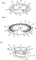
- a fluid circulator 1 of the circular type in this type of circulator we find a pump body 4 and an undulating membrane 2 this membrane being of discoidal shape.
- a first deflector 10 in the form of a ring can be seen surrounding the membrane 2 at its upstream edge 8 as well as a second deflector 10 disposed between the discharge orifice 6 and the downstream edge 9 of the membrane.
- the deflectors 10 act in the same way as those provided for the membrane 2 in the form of a longitudinal blade illustrated in figure 1 .
- At least two superposed deflectors 10 are provided upstream and/or downstream of the membrane 2 .
- the picture 3 we see represented three superimposed deflectors.
- the use of several superimposed deflectors 10 makes it possible to separate the main flow into several superimposed flows of secondary fluid and makes it possible to better channeling each of these flows in order to obtain laminar flows. This advantageous characteristic will be particularly suitable when the section of the propulsion chamber 5 at the level of the deflectors is large.
- a third type of circulator 1 is shown, namely a cylindrical circulator in which the undulating membrane 2 is of tubular shape.
- orientation means 7 are also provided in the form of cylindrical deflectors 10 arranged upstream and downstream of the membrane 2.
- the deflectors 10 are placed at a low distance from the edge of the undulating membrane 2, or from its support connecting it to the actuator, advantageously less than one fiftieth of the length separating the upstream 8 and downstream 9 edges of the undulating membrane 2.
- the first means orientation 7a is arranged at a distance from the upstream edge 8 of the membrane 2 which is less than one fiftieth of the length separating the upstream 8 and downstream 9 edges.
- the second orientation means 7b can be arranged at a distance from the downstream edge 9 of the membrane 2 which is less than one fiftieth of the length separating the upstream 8 and downstream 9 edges.
- deflectors further from the edges of the undulating membrane 2.
- FIG. 5 there is shown a variant embodiment of a circulator 1.
- this variant there are complementary orientation means 11, these orientation means complementary 11 are arranged in a plane perpendicular to a plane in which the first orientation means 7a extends and make it possible to prevent a circular displacement of the fluid between the inlet orifice 3 and the undulating membrane 2.
- complementary orientation means 11 are arranged in a plane perpendicular to a plane in which extends the second orientation means 7b and make it possible to prevent a circular displacement fluid between the discharge port and the undulating diaphragm 2.
- the complementary orientation means 11 make it possible to increase the hydraulic power of the circulator 1.
- the complementary orientation means 11 are, as shown in figure 5 , subject to the first orientation means 7a; advantageously the first orientation means 7a and the complementary orientation means 11 are formed in one piece.
- the orientation means 7a, 7b are respectively constituted by deflectors 10, however, in other embodiments, other devices may be used to orient the flow, in particular by providing two separate flow inlets, each oriented towards the top or the bottom of the membrane.
- the orientation means 7a and or 7b to comprise heat transfer elements making it possible to vary the fluidity of the fluid to be pumped and/or its temperature.
- This embodiment of the orientation means or means is shown in figure 6 with heating elements 12 carried by the first orientation means.
- complementary orientation means 11 which also fulfill the function of thermal diffusers since they extend from the orientation means carrying the heating elements 12.
- the heat transfer elements carried by the orientation 7a here include the heating means 12, but they could also include cooling means and / or a coolant transfer circuit.
- the orientation means 7 are not connected to the pump body 4 but are fixed between the drive means 13 of the membrane and the membrane 2 itself.
- the first orientation means 7a is connected via a spring effect connection to a movable part 14 of the drive means 13 to constitute an elastically deformable guide of the first orientation means with respect to the movable part 14.
- the movable part 14 By connecting an orientation means 7a or 7b via a spring-effect connection to the drive means 13 and more particularly to the movable part 14 of the drive means 13, the movable part 14 is both guided and damped by the orientation means 7a or 7b which is immersed in the fluid.
- the first orientation means 7a is obtained by a deflector 10, which is in the form of a crown, comprising at the level of the connection with the movable part 14 openings 15 giving a spring effect to the connection.
- first way orientation 7a is connected by a flexible connection 16a to the upstream edge 8 of the membrane 2, this first orientation means 7a forming with the membrane 2 and with the flexible connection 16, a sealed separation between two distinct spaces of the chamber of propulsion 5.
- the second orientation means 7b is connected by a second flexible connection 16b to the downstream edge 9 of the membrane 2, this second orientation means 7b forming with the membrane 2 and with the second flexible connection 16b, a sealed separation between two distinct spaces of the propulsion chamber 5 separated from each other by the membrane 2.
- first and second flexible connections 16a, 16b making it possible to form a seal between the part of the chamber of propulsion located above the membrane and that located below. This avoids the transverse flows of fluid between these two parts/spaces of the chamber during the displacement of the wave on the membrane 2.
Landscapes
- Engineering & Computer Science (AREA)
- Mechanical Engineering (AREA)
- General Engineering & Computer Science (AREA)
- Reciprocating Pumps (AREA)
Claims (12)
- Flüssigkeitszirkulator mit welliger Membran mit mindestens einer Einlassöffnung (3), einem Pumpenkörper (4), einer Vortriebskammer (5), mindestens einer Auslassöffnung (6) und einer welligen Membran (2), die mit einer Antriebseinrichtung (13) verbunden ist, um eine Wellenbewegung der Membran (2) zwischen ihrem stromaufwärtigen (8) und ihrem stromabwärtigen (9) Rand zu erzeugen, wobei die wellige Membran (2) geeignet ist, eine Flüssigkeit in Richtung der Auslassöffnung (6) zu bewegen, wobei der Zirkulator ferner eine erste Orientierungseinrichtung (7a) zum Orientieren einer in der Flüssigkeitsvortriebskammer (5) vorhandenen Flüssigkeit in die Nähe eines der Ränder (8; 9) der welligen Membran (2) aufweist, so dass es möglich ist, den Flüssigkeitsstrom in eine Richtung im Wesentlichen parallel zur Bewegung der Welle auf der Membran (2) zu kanalisieren, dadurch gekennzeichnet, dass die erste Orientierungseinrichtung (7a) über eine federgespannte Verbindung mit einem beweglichen Abschnitt (14) der Antriebseinrichtung (13) verbunden ist, um eine elastisch verformbare Führung der ersten Orientierungseinrichtung bezüglich des beweglichen Abschnitts (14) bereitzustellen.
- Flüssigkeitszirkulator nach Anspruch 1, wobei die erste Orientierungseinrichtung (7a) in der Nähe des stromaufwärtigen Randes (8) der welligen Membran (2) angeordnet ist und wobei eine zweite Orientierungseinrichtung (7b) in der Nähe des stromabwärtigen Randes (9) der welligen Membran (2) angeordnet ist.
- Flüssigkeitszirkulator nach einem der Ansprüche 1 oder 2, wobei die erste Orientierungseinrichtung (7a) mindestens ein Leitblech (10) aufweist.
- Flüssigkeitszirkulator nach Anspruch 2, wobei die zweite Orientierungseinrichtung (7b) mindestes ein Leitblech (10) aufweist.
- Flüssigkeitszirkulator nach Anspruch 3 oder 4, wobei das Leitblech (10) flexibel ist.
- Flüssigkeitszirkulator nach Anspruch 3 oder Anspruch 4, wobei das Leitblech (10) im Wesentlichen parallel zur Bewegung der Welle auf der Membran (2) angeordnet ist.
- Flüssigkeitszirkulator nach Anspruch 3, der mindestens zwei übereinander angeordnete Leitbleche (10) aufweist, so dass es möglich ist, den Hauptflüssigkeitsstrom in mehrere, übereinander strömende Ströme zu kanalisieren.
- Flüssigkeitszirkulator nach einem der Ansprüche 1 bis 6, wobei die ersten Orientierungseinrichtungen (7a) Wärmeübertragungselemente aufweisen, die die Temperatur der Flüssigkeit ändern können.
- Flüssigkeitszirkulator nach einem der Ansprüche 1 bis 7, wobei die erste Orientierungseinrichtung (7a) in einem Abstand vom stromaufwärtigen (8) oder stromabwärtigen Rand der Membran (2) angeordnet ist, der weniger als ein Fünfzehntel der Länge beträgt, die den stromaufwärtigen (8) vom stromabwärtigen (9) Rand trennt.
- Flüssigkeitszirkulator nach einem der Ansprüche 1 bis 9, der komplementäre Orientierungseinrichtungen (11) aufweist, die in einer Ebene senkrecht zu einer Ebene angeordnet sind, in der sich die erste Orientierungseinrichtung (7a) erstreckt.
- Flüssigkeitszirkulator nach Anspruch 10, wobei die komplementären Orientierungseinrichtungen (11) an der ersten Orientierungseinrichtung (7a) befestigt sind.
- Flüssigkeitszirkulator nach Anspruch 1, wobei die erste Orientierungseinrichtung (7a) über eine flexible Verbindung (16) mit dem stromaufwärtigen Rand (8) der Membran (2) verbunden ist, wobei die erste Orientierungseinrichtung (7a), zusammen mit der Membran (2) und der flexiblen Verbindung (16), eine dichte Sperre zwischen zwei verschiedenen Räumen der Vortriebskammer (5) bildet, die durch die Membran (2) voneinander getrennt sind.
Applications Claiming Priority (2)
| Application Number | Priority Date | Filing Date | Title |
|---|---|---|---|
| FR1760583A FR3073578B1 (fr) | 2017-11-10 | 2017-11-10 | Circulateur de fluide a membrane ondulante |
| PCT/EP2018/080749 WO2019092175A1 (fr) | 2017-11-10 | 2018-11-09 | Circulateur de fluide a membrane ondulante |
Publications (3)
| Publication Number | Publication Date |
|---|---|
| EP3707381A1 EP3707381A1 (de) | 2020-09-16 |
| EP3707381B1 true EP3707381B1 (de) | 2022-02-16 |
| EP3707381B8 EP3707381B8 (de) | 2022-03-23 |
Family
ID=60955259
Family Applications (1)
| Application Number | Title | Priority Date | Filing Date |
|---|---|---|---|
| EP18810891.4A Active EP3707381B8 (de) | 2017-11-10 | 2018-11-09 | Flüssigkeitszirkulator mit welliger membran |
Country Status (7)
| Country | Link |
|---|---|
| US (1) | US11512689B2 (de) |
| EP (1) | EP3707381B8 (de) |
| JP (1) | JP7158061B2 (de) |
| CN (1) | CN111433460B (de) |
| AU (1) | AU2018365313B2 (de) |
| FR (1) | FR3073578B1 (de) |
| WO (1) | WO2019092175A1 (de) |
Families Citing this family (19)
| Publication number | Priority date | Publication date | Assignee | Title |
|---|---|---|---|---|
| US9968720B2 (en) | 2016-04-11 | 2018-05-15 | CorWave SA | Implantable pump system having an undulating membrane |
| US10166319B2 (en) | 2016-04-11 | 2019-01-01 | CorWave SA | Implantable pump system having a coaxial ventricular cannula |
| AU2018242620B2 (en) | 2017-03-31 | 2023-11-16 | CorWave SA | Implantable pump system having a rectangular membrane |
| FR3073578B1 (fr) | 2017-11-10 | 2019-12-13 | Corwave | Circulateur de fluide a membrane ondulante |
| US10188779B1 (en) | 2017-11-29 | 2019-01-29 | CorWave SA | Implantable pump system having an undulating membrane with improved hydraulic performance |
| WO2020115607A2 (en) | 2018-12-05 | 2020-06-11 | CorWave SA | Apparatus and methods for coupling a blood pump to the heart |
| US10799625B2 (en) | 2019-03-15 | 2020-10-13 | CorWave SA | Systems and methods for controlling an implantable blood pump |
| FR3099748B1 (fr) * | 2019-08-09 | 2023-07-28 | Finx | Dispositif de déplacement d’un véhicule nautique |
| CN110425119B (zh) * | 2019-08-21 | 2025-01-24 | 劳特士(嘉兴)机械设备有限公司 | 一种气动泵吸装置 |
| EP4114504B1 (de) | 2020-03-06 | 2026-04-08 | CorWave SA | Implantierbare blutpumpe, die ein linearlager umfasst |
| CA3250624A1 (en) | 2022-04-26 | 2023-11-02 | CorWave SA | BLOOD PUMPS EQUIPPED WITH AN ENCAPSULATED ACTUATOR |
| FR3137658A1 (fr) * | 2022-07-05 | 2024-01-12 | Finx | Dispositif générateur de flux fluidique à membrane multi-directionnel |
| US12257427B2 (en) | 2022-11-15 | 2025-03-25 | CorWave SA | Implantable heart pump systems including an improved apical connector and/or graft connector |
| US12017059B2 (en) | 2022-11-15 | 2024-06-25 | CorWave SA | Implantable heart pump systems including an improved apical connector and/or graft connector |
| FR3144231A1 (fr) * | 2022-12-23 | 2024-06-28 | Finx | Propulseur hydraulique comprenant une carte électronique immérgée |
| FR3144105A1 (fr) * | 2022-12-23 | 2024-06-28 | Finx | système de mise en tension d’une membrane équipant un dispositif de générateur de flux fluidique |
| US12416301B2 (en) * | 2023-01-11 | 2025-09-16 | Southwest Research Institute | Traveling wave fluid energy machine |
| FR3147332A1 (fr) * | 2023-03-31 | 2024-10-04 | Finx | Dispositif générateur de flux fluidique comprenant une membrane à raideur décroissante |
| FR3147242A1 (fr) * | 2023-03-31 | 2024-10-04 | Finx | Déflecteur mobile pour dispositif générateur de flux fluidique à membrane |
Family Cites Families (155)
| Publication number | Priority date | Publication date | Assignee | Title |
|---|---|---|---|---|
| FR355700A (fr) * | 1905-06-28 | 1905-11-09 | Leopold Selme | Turbine à membranes ondulantes, reversible comme pompe |
| GB662047A (en) | 1949-11-21 | 1951-11-28 | George Aksel Thiberg | Improvements in diaphragm pumps and compressors |
| US2842067A (en) | 1954-10-12 | 1958-07-08 | Stevens Ronald John | Pumps for fluids, more especially liquids |
| US3107630A (en) | 1955-01-31 | 1963-10-22 | Textron Inc | Non-magnetic electro-hydraulic pump |
| US3165061A (en) | 1963-02-18 | 1965-01-12 | Edward H Smith | Method and apparatus employing acoustic energy for increasing fluid flow |
| GB1302541A (de) | 1969-02-07 | 1973-01-10 | ||
| US3608088A (en) | 1969-04-17 | 1971-09-28 | Univ Minnesota | Implantable blood pump |
| JPS5019840B1 (de) | 1970-12-30 | 1975-07-10 | ||
| US3743446A (en) | 1971-07-12 | 1973-07-03 | Atek Ind Inc | Standing wave pump |
| DE2522309C3 (de) | 1975-05-20 | 1979-10-11 | Waldemar 4500 Osnabrueck Riepe | Flüssigkeitspumpe |
| AU5665580A (en) | 1979-03-22 | 1980-09-25 | Wakelin, R.R.F. | Moving-wall type pump |
| US4277706A (en) | 1979-04-16 | 1981-07-07 | Nu-Tech Industries, Inc. | Actuator for heart pump |
| US4498851A (en) * | 1980-05-02 | 1985-02-12 | Piezo Electric Products, Inc. | Solid state blower |
| DE3207101C1 (de) | 1982-02-27 | 1983-10-06 | Dornier System Gmbh | Schrittmotor |
| US4488854A (en) | 1982-04-12 | 1984-12-18 | Miller Richard B | Constrained wave pump |
| US4648807A (en) | 1985-05-14 | 1987-03-10 | The Garrett Corporation | Compact piezoelectric fluidic air supply pump |
| US4753221A (en) | 1986-10-22 | 1988-06-28 | Intravascular Surgical Instruments, Inc. | Blood pumping catheter and method of use |
| US4918383A (en) | 1987-01-20 | 1990-04-17 | Huff Richard E | Membrane probe with automatic contact scrub action |
| JPS63229060A (ja) | 1987-03-18 | 1988-09-22 | アイシン精機株式会社 | 大動脈内バル−ンポンプ |
| JPH01174278A (ja) | 1987-12-28 | 1989-07-10 | Misuzu Erii:Kk | インバータ |
| US4906229A (en) | 1988-05-03 | 1990-03-06 | Nimbus Medical, Inc. | High-frequency transvalvular axisymmetric blood pump |
| US5011380A (en) | 1989-01-23 | 1991-04-30 | University Of South Florida | Magnetically actuated positive displacement pump |
| US4995857A (en) | 1989-04-07 | 1991-02-26 | Arnold John R | Left ventricular assist device and method for temporary and permanent procedures |
| US5324177A (en) | 1989-05-08 | 1994-06-28 | The Cleveland Clinic Foundation | Sealless rotodynamic pump with radially offset rotor |
| US4955856A (en) | 1989-06-30 | 1990-09-11 | Phillips Steven J | Method and apparatus for installing a ventricular assist device cannulae |
| FR2650862B1 (fr) * | 1989-08-11 | 1991-11-08 | Salmson Pompes | Dispositif de propulsion d'un fluide |
| JPH0636821B2 (ja) | 1990-03-08 | 1994-05-18 | 健二 山崎 | 体内埋設形の補助人工心臓 |
| DE4129970C1 (de) | 1991-09-10 | 1993-03-04 | Forschungsgesellschaft Fuer Biomedizinische Technik E.V., 5100 Aachen, De | |
| US5360445A (en) | 1991-11-06 | 1994-11-01 | International Business Machines Corporation | Blood pump actuator |
| US5982801A (en) | 1994-07-14 | 1999-11-09 | Quantum Sonic Corp., Inc | Momentum transfer apparatus |
| US5525041A (en) | 1994-07-14 | 1996-06-11 | Deak; David | Momemtum transfer pump |
| US5588812A (en) | 1995-04-19 | 1996-12-31 | Nimbus, Inc. | Implantable electric axial-flow blood pump |
| FR2744769B1 (fr) | 1996-02-12 | 1999-02-12 | Drevet Jean Baptiste | Circulateur de fluide a membrane vibrante |
| US5840070A (en) | 1996-02-20 | 1998-11-24 | Kriton Medical, Inc. | Sealless rotary blood pump |
| FR2744924B1 (fr) | 1996-02-21 | 1998-04-24 | Franchi Pierre | Dispositif generateur/regulateur de pression pour pompe d'assistance cardiaque implantable du type a ballonnet de contrepression |
| DE19613564C1 (de) | 1996-04-04 | 1998-01-08 | Guenter Prof Dr Rau | Intravasale Blutpumpe |
| DE19625300A1 (de) | 1996-06-25 | 1998-01-02 | Guenter Prof Dr Rau | Blutpumpe |
| US5964694A (en) | 1997-04-02 | 1999-10-12 | Guidant Corporation | Method and apparatus for cardiac blood flow assistance |
| US7182727B2 (en) | 1997-07-11 | 2007-02-27 | A—Med Systems Inc. | Single port cardiac support apparatus |
| US6395026B1 (en) | 1998-05-15 | 2002-05-28 | A-Med Systems, Inc. | Apparatus and methods for beating heart bypass surgery |
| US6532964B2 (en) | 1997-07-11 | 2003-03-18 | A-Med Systems, Inc. | Pulmonary and circulatory blood flow support devices and methods for heart surgery procedures |
| US6123725A (en) | 1997-07-11 | 2000-09-26 | A-Med Systems, Inc. | Single port cardiac support apparatus |
| US6176822B1 (en) | 1998-03-31 | 2001-01-23 | Impella Cardiotechnik Gmbh | Intracardiac blood pump |
| US6079214A (en) | 1998-08-06 | 2000-06-27 | Face International Corporation | Standing wave pump |
| US6659740B2 (en) | 1998-08-11 | 2003-12-09 | Jean-Baptiste Drevet | Vibrating membrane fluid circulator |
| RU2143343C1 (ru) * | 1998-11-03 | 1999-12-27 | Самсунг Электроникс Ко., Лтд. | Микроинжектор и способ изготовления микроинжектора |
| AUPQ090499A0 (en) | 1999-06-10 | 1999-07-01 | Peters, William S | Heart assist device and system |
| US6346071B1 (en) | 1999-07-16 | 2002-02-12 | World Heart Corporation | Inflow conduit assembly for a ventricular assist device |
| JP2001034568A (ja) | 1999-07-21 | 2001-02-09 | Fujitsu Ltd | 論理パス確立方法及び記憶媒体 |
| DE29921352U1 (de) | 1999-12-04 | 2001-04-12 | Impella Cardiotechnik AG, 52074 Aachen | Intravasale Blutpumpe |
| US7168138B2 (en) | 2000-03-27 | 2007-01-30 | Newfrey Llc | Resilient clip fastener |
| US6530876B1 (en) | 2000-04-25 | 2003-03-11 | Paul A. Spence | Supplemental heart pump methods and systems for supplementing blood through the heart |
| US6726648B2 (en) | 2000-08-14 | 2004-04-27 | The University Of Miami | Valved apical conduit with trocar for beating-heart ventricular assist device placement |
| DE10059714C1 (de) | 2000-12-01 | 2002-05-08 | Impella Cardiotech Ag | Intravasale Pumpe |
| US20020095210A1 (en) | 2001-01-16 | 2002-07-18 | Finnegan Michael T. | Heart pump graft connector and system |
| US6658740B2 (en) | 2001-03-16 | 2003-12-09 | Wahl Clipper Corporation | Blade assembly for a vibrator motor |
| DE10119691A1 (de) | 2001-04-20 | 2002-11-21 | Deutsch Zentr Luft & Raumfahrt | System zum Unterstützen des linken Herzventrikels |
| US6723039B2 (en) | 2001-04-27 | 2004-04-20 | The Foundry, Inc. | Methods, systems and devices relating to implantable fluid pumps |
| US6493254B1 (en) | 2001-06-28 | 2002-12-10 | Intel Corporation | Current leakage reduction for loaded bit-lines in on-chip memory structures |
| AT412416B (de) * | 2001-10-23 | 2005-02-25 | Zackl Wilhelm | Ventillose pumpe |
| US6672847B2 (en) | 2001-12-27 | 2004-01-06 | Pratt & Whitney Canada Corp. | Standing wave excitation cavity fluid pump |
| US20060155158A1 (en) | 2002-06-11 | 2006-07-13 | Aboul-Hosn Walid N | Percutaneously introduced blood pump and related methods |
| US6732501B2 (en) | 2002-06-26 | 2004-05-11 | Heartware, Inc. | Ventricular connector |
| AU2002951685A0 (en) | 2002-09-30 | 2002-10-17 | Ventrassist Pty Ltd | Physiological demand responsive control system |
| US7889877B2 (en) | 2003-06-30 | 2011-02-15 | Nxp B.V. | Device for generating a medium stream |
| FR2861910B1 (fr) | 2003-10-29 | 2006-01-13 | Jean Baptiste Drevet | Machine electromagnetique a membrane deformable et moteur electromagnetique adapte a une telle machine |
| US7520850B2 (en) | 2003-11-19 | 2009-04-21 | Transoma Medical, Inc. | Feedback control and ventricular assist devices |
| DE102004019721A1 (de) | 2004-03-18 | 2005-10-06 | Medos Medizintechnik Ag | Pumpe |
| US20050261543A1 (en) | 2004-05-18 | 2005-11-24 | Yusuke Abe | Implantable artificial ventricular assist device |
| US7374565B2 (en) | 2004-05-28 | 2008-05-20 | Ethicon Endo-Surgery, Inc. | Bi-directional infuser pump with volume braking for hydraulically controlling an adjustable gastric band |
| US7108652B2 (en) | 2004-06-07 | 2006-09-19 | University Of Florida Research Foundation, Inc. | Multi-chamber self-regulating ventricular assist device |
| US7588530B2 (en) | 2004-07-19 | 2009-09-15 | Marlin Stephen Heilman | Devices, systems and methods for assisting blood flow |
| AU2005272610B2 (en) | 2004-08-13 | 2011-10-20 | Procyrion, Inc. | Method and apparatus for long-term assisting a left ventricle to pump blood |
| DE102004049986A1 (de) | 2004-10-14 | 2006-04-20 | Impella Cardiosystems Gmbh | Intrakardiale Blutpumpe |
| WO2007053881A1 (en) | 2005-11-08 | 2007-05-18 | Ventrassist Pty Ltd | Improvements to control systems and power systems for rotary blood pumps |
| US9144669B2 (en) | 2005-11-16 | 2015-09-29 | Heartware, Inc. | Implantation procedure for blood pumps |
| US20080232987A1 (en) * | 2006-11-28 | 2008-09-25 | S.A.M. Amstar | Diaphragm circulator |
| US9744279B2 (en) | 2005-12-08 | 2017-08-29 | Heartware, Inc. | Implant connector |
| CA2636105C (en) | 2006-01-27 | 2015-05-05 | Circulite, Inc | Heart assist system |
| EP1979021B1 (de) | 2006-01-30 | 2019-07-24 | 3R International Co., Ltd | Biventrikuläre dual-impuls-hilfsvorrichtung |
| AU2013203301B2 (en) | 2006-05-31 | 2015-10-29 | Star Bp, Inc. | Heart Assist Device |
| US20070299297A1 (en) | 2006-06-26 | 2007-12-27 | Robert Jarvik | Textured conforming shell for stabilization of the interface of precision heart assist device components to tissues |
| FR2905147B1 (fr) | 2006-08-25 | 2008-10-31 | Ubbink Garden B V | Pompe de circulation de fluide a membrane vibrante. |
| US8333686B2 (en) | 2006-08-30 | 2012-12-18 | Circulite, Inc. | Cannula insertion devices, systems, and methods including a compressible member |
| US8432057B2 (en) | 2007-05-01 | 2013-04-30 | Pliant Energy Systems Llc | Pliant or compliant elements for harnessing the forces of moving fluid to transport fluid or generate electricity |
| US9145875B2 (en) | 2007-05-01 | 2015-09-29 | Pliant Energy Systems Llc | Ribbon transducer and pump apparatuses, methods and systems |
| US7696634B2 (en) | 2007-05-01 | 2010-04-13 | Pliant Energy Systems Llc | Pliant mechanisms for extracting power from moving fluid |
| AU2008261920A1 (en) | 2007-06-06 | 2008-12-18 | Worldheart Corporation | Wearable VAD controller with reserve battery |
| WO2009024308A1 (de) | 2007-08-17 | 2009-02-26 | Rheinisch-Westfälische Technische Hochschule Aachen | Linearantrieb und pumpsystem, insbesondere kunstherz |
| CA2700849C (en) | 2007-09-25 | 2016-07-26 | Correx, Inc. | Applicator, assembly, and method for connecting an inlet conduit to a hollow organ |
| GB0718943D0 (en) | 2007-09-28 | 2007-11-07 | Univ Nottingham | Mechanical support |
| US8343029B2 (en) | 2007-10-24 | 2013-01-01 | Circulite, Inc. | Transseptal cannula, tip, delivery system, and method |
| US8821366B2 (en) | 2007-10-24 | 2014-09-02 | Circulite, Inc. | Transseptal cannula, tip, delivery system, and method |
| EP2254616B1 (de) | 2008-01-23 | 2016-07-06 | DEKA Products Limited Partnership | Einwegflüssigkeitshandhabungs-kassette für peritonealdialyse |
| WO2009099644A1 (en) | 2008-02-08 | 2009-08-13 | Heartware, Inc. | Ventricular assist device for intraventricular placement |
| GB0813603D0 (en) | 2008-07-25 | 2008-09-03 | Cardio Carbon Technology Ltd | Ventricular assist system |
| FR2934652B1 (fr) * | 2008-08-01 | 2013-01-11 | Ams R & D Sas | Pompe a membrane ondulante de rendement ameliore. |
| FR2934651B1 (fr) * | 2008-08-01 | 2010-08-27 | Ams R & D Sas | Pompe a membrane ondulante perfectionnee. |
| US8449444B2 (en) | 2009-02-27 | 2013-05-28 | Thoratec Corporation | Blood flow meter |
| US8366401B2 (en) | 2009-04-16 | 2013-02-05 | The Board Of Regents Of The University Of Texas Systems | Positive displacement pump system and method with rotating valve |
| US8167593B2 (en) | 2009-04-16 | 2012-05-01 | The Board Of Regents Of The University Of Texas System | System and method for pump with deformable bearing surface |
| WO2011056823A2 (en) | 2009-11-03 | 2011-05-12 | Coherex Medical, Inc. | Ventricular assist device and related methods |
| US8152845B2 (en) | 2009-12-30 | 2012-04-10 | Thoratec Corporation | Blood pump system with mounting cuff |
| US8562508B2 (en) | 2009-12-30 | 2013-10-22 | Thoratec Corporation | Mobility-enhancing blood pump system |
| DE102010009670B4 (de) * | 2010-02-27 | 2013-09-19 | Knf Neuberger Gmbh | Membranpumpe |
| EP2542271B1 (de) | 2010-03-03 | 2014-02-26 | The Secretary, Department Of Atomic Energy, Govt. of India | Auf flexibler magnetmembran basierendes betätigungssystem und vorrichtungen damit |
| AU2011222505B2 (en) | 2010-03-05 | 2014-01-23 | Minnetronix Inc. | Portable controller with integral power source for mechanical circulation support systems |
| US20110260449A1 (en) | 2010-04-21 | 2011-10-27 | Pokorney James L | Apical access and control devices |
| US9089635B2 (en) | 2010-06-22 | 2015-07-28 | Thoratec Corporation | Apparatus and method for modifying pressure-flow characteristics of a pump |
| US8870739B2 (en) | 2010-08-06 | 2014-10-28 | Heartware, Inc. | Conduit device for use with a ventricular assist device |
| US9227001B2 (en) | 2010-10-07 | 2016-01-05 | Everheart Systems Inc. | High efficiency blood pump |
| US8556795B2 (en) | 2010-11-23 | 2013-10-15 | Minnetronix Inc. | Portable controller with integral power source for mechanical circulation support systems |
| AU2011338308B2 (en) | 2010-12-09 | 2015-07-30 | Heartware, Inc. | Controller and power source for implantable blood pump |
| CN103384957B (zh) | 2011-01-10 | 2017-09-08 | 本亚明·彼得罗·菲拉尔多 | 用于例如为推进产生波状运动和用于利用运动流体的能量的机构 |
| US9149613B2 (en) | 2011-02-16 | 2015-10-06 | Sequana Medical Ag | Apparatus and methods for treating intracorporeal fluid accumulation |
| PL218244B1 (pl) | 2011-02-28 | 2014-10-31 | Fundacja Rozwoju Kardiochirurgii Im Prof Zbigniewa Religi | Pompa krwi, zwłaszcza implantowalna pneumatyczna komora wspomagania serca |
| JP5502017B2 (ja) | 2011-04-15 | 2014-05-28 | 株式会社テクノ高槻 | 電磁振動型ダイヤフラムポンプ |
| CN103635210A (zh) | 2011-05-05 | 2014-03-12 | 柏林心脏有限公司 | 血泵 |
| EP2524709A1 (de) | 2011-05-16 | 2012-11-21 | Berlin Heart GmbH | Verbindungssystem zum lösbaren Fixieren eines hohlzylindrischen Bauteils an einer Ausnehmung |
| US9731057B2 (en) | 2011-07-28 | 2017-08-15 | Fineheart | Removable heart pump, and method implemented in such a pump |
| CN102904448B (zh) | 2011-07-29 | 2015-07-22 | 比亚迪股份有限公司 | 一种开关电源的控制芯片和开关电源 |
| US10823164B2 (en) | 2011-08-25 | 2020-11-03 | Ecolab Usa Inc. | Diaphragm pump for dosing a fluid capable of automatic degassing and an according method |
| US8821527B2 (en) | 2011-09-07 | 2014-09-02 | Circulite, Inc. | Cannula tips, tissue attachment rings, and methods of delivering and using the same |
| KR101341326B1 (ko) * | 2011-12-15 | 2013-12-13 | (주)에스티아이 | 플렉시블 박막 기판 고정장치 |
| US8579790B2 (en) | 2012-01-05 | 2013-11-12 | Thoratec Corporation | Apical ring for ventricular assist device |
| US9199019B2 (en) | 2012-08-31 | 2015-12-01 | Thoratec Corporation | Ventricular cuff |
| EP3159023B1 (de) | 2012-03-05 | 2017-11-29 | Tc1 Llc | Methode zur kalibrierung implantierbarer medizinischer pumpen |
| ES3041040T3 (en) | 2012-03-26 | 2025-11-06 | Procyrion Inc | Systems and methods for fluid flows and/or pressures for circulation and perfusion enhancement |
| US9289110B2 (en) | 2012-04-05 | 2016-03-22 | Stryker Corporation | Control for surgical fluid management pump system |
| EP3136117B1 (de) | 2012-05-24 | 2020-08-19 | HeartWare, Inc. | Niedrigenergie-batteriepack mit sicherheitssystem |
| US9364596B2 (en) | 2013-01-04 | 2016-06-14 | HeartWave, Inc. | Controller and power source for implantable blood pump |
| US9398951B2 (en) | 2013-03-12 | 2016-07-26 | St. Jude Medical, Cardiology Division, Inc. | Self-actuating sealing portions for paravalvular leak protection |
| US8882477B2 (en) | 2013-03-14 | 2014-11-11 | Circulite, Inc. | Magnetically levitated and driven blood pump and method for using the same |
| EP3077018B1 (de) | 2013-12-04 | 2021-10-27 | Heartware, Inc. | Geformtes ventrikuläres unterstützungssystem |
| US9786150B2 (en) | 2014-04-15 | 2017-10-10 | Tci Llc | Methods and systems for providing battery feedback to patient |
| EP3131596B1 (de) | 2014-04-15 | 2020-07-22 | Tc1 Llc | Verfahren und systeme zur steuerung einer blutpumpe |
| FR3021074B1 (fr) | 2014-05-14 | 2016-05-27 | Saint Gobain Performance Plastics France | Pompe a membrane |
| US9861728B2 (en) | 2014-05-20 | 2018-01-09 | Circulite, Inc. | Heart assist system and methods |
| US9526819B2 (en) | 2014-09-26 | 2016-12-27 | Ch Biomedical (Usa), Inc. | Ventricular assist device controller with integrated power source |
| US10166318B2 (en) | 2015-02-12 | 2019-01-01 | Tc1 Llc | System and method for controlling the position of a levitated rotor |
| FR3032917B1 (fr) * | 2015-02-20 | 2017-02-17 | Valeo Systemes Thermiques | Module de conditionnement d'air d'un habitacle de vehicule automobile |
| CN107708404B (zh) | 2015-05-04 | 2021-08-31 | 约曼公司 | 手持工具组件、连接件和制造手持工具的方法 |
| EP4047216B1 (de) | 2015-07-06 | 2024-05-29 | Levitronix GmbH | Elektromagnetischer drehantrieb |
| WO2017087717A1 (en) | 2015-11-20 | 2017-05-26 | Tc1 Llc | Blood pump controllers having daisy-chained batteries |
| EP3377136B1 (de) | 2015-11-20 | 2020-05-06 | Tc1 Llc | Energieverwaltung von blutpumpensteuergeräten |
| WO2017161317A1 (en) | 2016-03-18 | 2017-09-21 | Everheart Systems Inc. | Cardiac connection for ventricular assist device |
| US9968720B2 (en) | 2016-04-11 | 2018-05-15 | CorWave SA | Implantable pump system having an undulating membrane |
| US10166319B2 (en) | 2016-04-11 | 2019-01-01 | CorWave SA | Implantable pump system having a coaxial ventricular cannula |
| FR3054861B1 (fr) | 2016-08-02 | 2019-08-23 | Zodiac Aerotechnics | Procede de pilotage d'une pompe a membrane ondulante, et systeme pilote de pompe a membrane ondulante |
| US10894116B2 (en) | 2016-08-22 | 2021-01-19 | Tc1 Llc | Heart pump cuff |
| AU2018242620B2 (en) | 2017-03-31 | 2023-11-16 | CorWave SA | Implantable pump system having a rectangular membrane |
| FR3073578B1 (fr) | 2017-11-10 | 2019-12-13 | Corwave | Circulateur de fluide a membrane ondulante |
| US10188779B1 (en) | 2017-11-29 | 2019-01-29 | CorWave SA | Implantable pump system having an undulating membrane with improved hydraulic performance |
| WO2020115607A2 (en) | 2018-12-05 | 2020-06-11 | CorWave SA | Apparatus and methods for coupling a blood pump to the heart |
| US10799625B2 (en) | 2019-03-15 | 2020-10-13 | CorWave SA | Systems and methods for controlling an implantable blood pump |
-
2017
- 2017-11-10 FR FR1760583A patent/FR3073578B1/fr active Active
-
2018
- 2018-11-09 CN CN201880078891.9A patent/CN111433460B/zh active Active
- 2018-11-09 EP EP18810891.4A patent/EP3707381B8/de active Active
- 2018-11-09 US US16/762,909 patent/US11512689B2/en active Active
- 2018-11-09 JP JP2020525986A patent/JP7158061B2/ja active Active
- 2018-11-09 WO PCT/EP2018/080749 patent/WO2019092175A1/fr not_active Ceased
- 2018-11-09 AU AU2018365313A patent/AU2018365313B2/en active Active
Also Published As
| Publication number | Publication date |
|---|---|
| US11512689B2 (en) | 2022-11-29 |
| FR3073578A1 (fr) | 2019-05-17 |
| EP3707381B8 (de) | 2022-03-23 |
| AU2018365313B2 (en) | 2024-05-09 |
| WO2019092175A1 (fr) | 2019-05-16 |
| US20210172429A1 (en) | 2021-06-10 |
| CN111433460B (zh) | 2022-10-04 |
| FR3073578B1 (fr) | 2019-12-13 |
| AU2018365313A1 (en) | 2020-05-21 |
| CN111433460A (zh) | 2020-07-17 |
| EP3707381A1 (de) | 2020-09-16 |
| JP7158061B2 (ja) | 2022-10-21 |
| JP2021502513A (ja) | 2021-01-28 |
Similar Documents
| Publication | Publication Date | Title |
|---|---|---|
| EP3707381B1 (de) | Flüssigkeitszirkulator mit welliger membran | |
| EP2740905B1 (de) | Splitter einer axialen turbomaschine, zugehoriger verdichter und axiale turbomaschine | |
| EP2756252B1 (de) | Wärmeübertragungsvorrichtung mit kapillarpumpung | |
| FR2986847A1 (fr) | Clapet anti-retour a membrane | |
| EP2352922A1 (de) | Schaufeln mit öffnungen aufweisender diffuser | |
| EP3869993B1 (de) | Hairstyling-gerät mit einer flüssigkeitsentleerungsvorrichtung | |
| EP2430314B1 (de) | Zentrifugalpumpe mit doppeltem auslass | |
| FR3106621A1 (fr) | Turbomachine pour aéronef équipée d’un système thermo-acoustique. | |
| EP1969232B1 (de) | Membranzirkulator | |
| FR2997485A1 (fr) | Echangeur thermique, notamment pour vehicule automobile | |
| EP2879955B1 (de) | Lufteinlass für hubschraubermotor mit vergrösserten umfangseinlasslippen | |
| EP3640467B1 (de) | Turbotriebwerk mit thermoakustischem system | |
| WO2017203143A1 (fr) | Répartiteur d'air et véhicule comprenant ce répartiteur d'air | |
| EP3452772B1 (de) | Wärmetauscher aus kunststoff und fahrzeug mit diesem wärmetauscher | |
| FR3087855A1 (fr) | Un turbocompresseur centrifuge ayant un trajet de flux de gaz comportant une chambre de detente | |
| FR3079605A1 (fr) | Echangeur thermique a plaques muni d'un bouclier de repartition de debit d'un fluide pour turbomoteur | |
| EP3027995B1 (de) | Verdampfer mit rückschlagvorrichtung für zweiphasigen kreislauf | |
| EP2799666B1 (de) | Spiralgehäuse mit zwei Volumina für Gasturbine | |
| EP3482148B1 (de) | Wärmetauscher und fahrzeug mit besagtem tauscher | |
| FR3122453A1 (fr) | Elément chauffant pour gaz d’échappement | |
| FR3115333A1 (fr) | Piston pour pompe de fluide cryogénique | |
| FR3099525A1 (fr) | Système de gestion thermique | |
| WO2024200306A1 (fr) | Déflecteur mobile pour dispositif générateur de flux fluidique à membrane | |
| FR2917820A1 (fr) | Bride de collecteur pour un echangeur de chaleur | |
| EP3054168B1 (de) | Vorrichtung zum einspeisen eines gases in einen geschlossenen kreislauf |
Legal Events
| Date | Code | Title | Description |
|---|---|---|---|
| STAA | Information on the status of an ep patent application or granted ep patent |
Free format text: STATUS: UNKNOWN |
|
| STAA | Information on the status of an ep patent application or granted ep patent |
Free format text: STATUS: THE INTERNATIONAL PUBLICATION HAS BEEN MADE |
|
| PUAI | Public reference made under article 153(3) epc to a published international application that has entered the european phase |
Free format text: ORIGINAL CODE: 0009012 |
|
| STAA | Information on the status of an ep patent application or granted ep patent |
Free format text: STATUS: REQUEST FOR EXAMINATION WAS MADE |
|
| 17P | Request for examination filed |
Effective date: 20200604 |
|
| AK | Designated contracting states |
Kind code of ref document: A1 Designated state(s): AL AT BE BG CH CY CZ DE DK EE ES FI FR GB GR HR HU IE IS IT LI LT LU LV MC MK MT NL NO PL PT RO RS SE SI SK SM TR |
|
| AX | Request for extension of the european patent |
Extension state: BA ME |
|
| DAV | Request for validation of the european patent (deleted) | ||
| DAX | Request for extension of the european patent (deleted) | ||
| STAA | Information on the status of an ep patent application or granted ep patent |
Free format text: STATUS: EXAMINATION IS IN PROGRESS |
|
| 17Q | First examination report despatched |
Effective date: 20210305 |
|
| GRAP | Despatch of communication of intention to grant a patent |
Free format text: ORIGINAL CODE: EPIDOSNIGR1 |
|
| STAA | Information on the status of an ep patent application or granted ep patent |
Free format text: STATUS: GRANT OF PATENT IS INTENDED |
|
| INTG | Intention to grant announced |
Effective date: 20211007 |
|
| GRAS | Grant fee paid |
Free format text: ORIGINAL CODE: EPIDOSNIGR3 |
|
| GRAA | (expected) grant |
Free format text: ORIGINAL CODE: 0009210 |
|
| STAA | Information on the status of an ep patent application or granted ep patent |
Free format text: STATUS: THE PATENT HAS BEEN GRANTED |
|
| GRAT | Correction requested after decision to grant or after decision to maintain patent in amended form |
Free format text: ORIGINAL CODE: EPIDOSNCDEC |
|
| AK | Designated contracting states |
Kind code of ref document: B1 Designated state(s): AL AT BE BG CH CY CZ DE DK EE ES FI FR GB GR HR HU IE IS IT LI LT LU LV MC MK MT NL NO PL PT RO RS SE SI SK SM TR |
|
| REG | Reference to a national code |
Ref country code: GB Ref legal event code: FG4D Free format text: NOT ENGLISH |
|
| REG | Reference to a national code |
Ref country code: CH Ref legal event code: PK Free format text: RECTIFICATION B8 Ref country code: CH Ref legal event code: EP |
|
| RAP4 | Party data changed (patent owner data changed or rights of a patent transferred) |
Owner name: CORWAVE SA |
|
| REG | Reference to a national code |
Ref country code: DE Ref legal event code: R096 Ref document number: 602018030982 Country of ref document: DE |
|
| REG | Reference to a national code |
Ref country code: AT Ref legal event code: REF Ref document number: 1469038 Country of ref document: AT Kind code of ref document: T Effective date: 20220315 |
|
| RAP4 | Party data changed (patent owner data changed or rights of a patent transferred) |
Owner name: CORWAVE SA |
|
| REG | Reference to a national code |
Ref country code: IE Ref legal event code: FG4D Free format text: LANGUAGE OF EP DOCUMENT: FRENCH |
|
| REG | Reference to a national code |
Ref country code: LT Ref legal event code: MG9D |
|
| REG | Reference to a national code |
Ref country code: NL Ref legal event code: MP Effective date: 20220216 |
|
| REG | Reference to a national code |
Ref country code: AT Ref legal event code: MK05 Ref document number: 1469038 Country of ref document: AT Kind code of ref document: T Effective date: 20220216 |
|
| PG25 | Lapsed in a contracting state [announced via postgrant information from national office to epo] |
Ref country code: SE Free format text: LAPSE BECAUSE OF FAILURE TO SUBMIT A TRANSLATION OF THE DESCRIPTION OR TO PAY THE FEE WITHIN THE PRESCRIBED TIME-LIMIT Effective date: 20220216 Ref country code: RS Free format text: LAPSE BECAUSE OF FAILURE TO SUBMIT A TRANSLATION OF THE DESCRIPTION OR TO PAY THE FEE WITHIN THE PRESCRIBED TIME-LIMIT Effective date: 20220216 Ref country code: PT Free format text: LAPSE BECAUSE OF FAILURE TO SUBMIT A TRANSLATION OF THE DESCRIPTION OR TO PAY THE FEE WITHIN THE PRESCRIBED TIME-LIMIT Effective date: 20220616 Ref country code: NO Free format text: LAPSE BECAUSE OF FAILURE TO SUBMIT A TRANSLATION OF THE DESCRIPTION OR TO PAY THE FEE WITHIN THE PRESCRIBED TIME-LIMIT Effective date: 20220516 Ref country code: NL Free format text: LAPSE BECAUSE OF FAILURE TO SUBMIT A TRANSLATION OF THE DESCRIPTION OR TO PAY THE FEE WITHIN THE PRESCRIBED TIME-LIMIT Effective date: 20220216 Ref country code: LT Free format text: LAPSE BECAUSE OF FAILURE TO SUBMIT A TRANSLATION OF THE DESCRIPTION OR TO PAY THE FEE WITHIN THE PRESCRIBED TIME-LIMIT Effective date: 20220216 Ref country code: HR Free format text: LAPSE BECAUSE OF FAILURE TO SUBMIT A TRANSLATION OF THE DESCRIPTION OR TO PAY THE FEE WITHIN THE PRESCRIBED TIME-LIMIT Effective date: 20220216 Ref country code: ES Free format text: LAPSE BECAUSE OF FAILURE TO SUBMIT A TRANSLATION OF THE DESCRIPTION OR TO PAY THE FEE WITHIN THE PRESCRIBED TIME-LIMIT Effective date: 20220216 Ref country code: BG Free format text: LAPSE BECAUSE OF FAILURE TO SUBMIT A TRANSLATION OF THE DESCRIPTION OR TO PAY THE FEE WITHIN THE PRESCRIBED TIME-LIMIT Effective date: 20220516 |
|
| PG25 | Lapsed in a contracting state [announced via postgrant information from national office to epo] |
Ref country code: PL Free format text: LAPSE BECAUSE OF FAILURE TO SUBMIT A TRANSLATION OF THE DESCRIPTION OR TO PAY THE FEE WITHIN THE PRESCRIBED TIME-LIMIT Effective date: 20220216 Ref country code: LV Free format text: LAPSE BECAUSE OF FAILURE TO SUBMIT A TRANSLATION OF THE DESCRIPTION OR TO PAY THE FEE WITHIN THE PRESCRIBED TIME-LIMIT Effective date: 20220216 Ref country code: GR Free format text: LAPSE BECAUSE OF FAILURE TO SUBMIT A TRANSLATION OF THE DESCRIPTION OR TO PAY THE FEE WITHIN THE PRESCRIBED TIME-LIMIT Effective date: 20220517 Ref country code: FI Free format text: LAPSE BECAUSE OF FAILURE TO SUBMIT A TRANSLATION OF THE DESCRIPTION OR TO PAY THE FEE WITHIN THE PRESCRIBED TIME-LIMIT Effective date: 20220216 Ref country code: AT Free format text: LAPSE BECAUSE OF FAILURE TO SUBMIT A TRANSLATION OF THE DESCRIPTION OR TO PAY THE FEE WITHIN THE PRESCRIBED TIME-LIMIT Effective date: 20220216 |
|
| PG25 | Lapsed in a contracting state [announced via postgrant information from national office to epo] |
Ref country code: IS Free format text: LAPSE BECAUSE OF FAILURE TO SUBMIT A TRANSLATION OF THE DESCRIPTION OR TO PAY THE FEE WITHIN THE PRESCRIBED TIME-LIMIT Effective date: 20220617 |
|
| PG25 | Lapsed in a contracting state [announced via postgrant information from national office to epo] |
Ref country code: SM Free format text: LAPSE BECAUSE OF FAILURE TO SUBMIT A TRANSLATION OF THE DESCRIPTION OR TO PAY THE FEE WITHIN THE PRESCRIBED TIME-LIMIT Effective date: 20220216 Ref country code: SK Free format text: LAPSE BECAUSE OF FAILURE TO SUBMIT A TRANSLATION OF THE DESCRIPTION OR TO PAY THE FEE WITHIN THE PRESCRIBED TIME-LIMIT Effective date: 20220216 Ref country code: RO Free format text: LAPSE BECAUSE OF FAILURE TO SUBMIT A TRANSLATION OF THE DESCRIPTION OR TO PAY THE FEE WITHIN THE PRESCRIBED TIME-LIMIT Effective date: 20220216 Ref country code: EE Free format text: LAPSE BECAUSE OF FAILURE TO SUBMIT A TRANSLATION OF THE DESCRIPTION OR TO PAY THE FEE WITHIN THE PRESCRIBED TIME-LIMIT Effective date: 20220216 Ref country code: DK Free format text: LAPSE BECAUSE OF FAILURE TO SUBMIT A TRANSLATION OF THE DESCRIPTION OR TO PAY THE FEE WITHIN THE PRESCRIBED TIME-LIMIT Effective date: 20220216 Ref country code: CZ Free format text: LAPSE BECAUSE OF FAILURE TO SUBMIT A TRANSLATION OF THE DESCRIPTION OR TO PAY THE FEE WITHIN THE PRESCRIBED TIME-LIMIT Effective date: 20220216 |
|
| REG | Reference to a national code |
Ref country code: DE Ref legal event code: R097 Ref document number: 602018030982 Country of ref document: DE |
|
| PG25 | Lapsed in a contracting state [announced via postgrant information from national office to epo] |
Ref country code: AL Free format text: LAPSE BECAUSE OF FAILURE TO SUBMIT A TRANSLATION OF THE DESCRIPTION OR TO PAY THE FEE WITHIN THE PRESCRIBED TIME-LIMIT Effective date: 20220216 |
|
| PLBE | No opposition filed within time limit |
Free format text: ORIGINAL CODE: 0009261 |
|
| STAA | Information on the status of an ep patent application or granted ep patent |
Free format text: STATUS: NO OPPOSITION FILED WITHIN TIME LIMIT |
|
| 26N | No opposition filed |
Effective date: 20221117 |
|
| PG25 | Lapsed in a contracting state [announced via postgrant information from national office to epo] |
Ref country code: SI Free format text: LAPSE BECAUSE OF FAILURE TO SUBMIT A TRANSLATION OF THE DESCRIPTION OR TO PAY THE FEE WITHIN THE PRESCRIBED TIME-LIMIT Effective date: 20220216 |
|
| P01 | Opt-out of the competence of the unified patent court (upc) registered |
Effective date: 20230316 |
|
| PG25 | Lapsed in a contracting state [announced via postgrant information from national office to epo] |
Ref country code: MC Free format text: LAPSE BECAUSE OF FAILURE TO SUBMIT A TRANSLATION OF THE DESCRIPTION OR TO PAY THE FEE WITHIN THE PRESCRIBED TIME-LIMIT Effective date: 20220216 |
|
| REG | Reference to a national code |
Ref country code: CH Ref legal event code: PL |
|
| REG | Reference to a national code |
Ref country code: BE Ref legal event code: MM Effective date: 20221130 |
|
| PG25 | Lapsed in a contracting state [announced via postgrant information from national office to epo] |
Ref country code: LI Free format text: LAPSE BECAUSE OF NON-PAYMENT OF DUE FEES Effective date: 20221130 Ref country code: IT Free format text: LAPSE BECAUSE OF FAILURE TO SUBMIT A TRANSLATION OF THE DESCRIPTION OR TO PAY THE FEE WITHIN THE PRESCRIBED TIME-LIMIT Effective date: 20220216 Ref country code: CH Free format text: LAPSE BECAUSE OF NON-PAYMENT OF DUE FEES Effective date: 20221130 |
|
| PG25 | Lapsed in a contracting state [announced via postgrant information from national office to epo] |
Ref country code: LU Free format text: LAPSE BECAUSE OF NON-PAYMENT OF DUE FEES Effective date: 20221109 |
|
| PG25 | Lapsed in a contracting state [announced via postgrant information from national office to epo] |
Ref country code: IE Free format text: LAPSE BECAUSE OF NON-PAYMENT OF DUE FEES Effective date: 20221109 |
|
| PG25 | Lapsed in a contracting state [announced via postgrant information from national office to epo] |
Ref country code: BE Free format text: LAPSE BECAUSE OF NON-PAYMENT OF DUE FEES Effective date: 20221130 |
|
| PG25 | Lapsed in a contracting state [announced via postgrant information from national office to epo] |
Ref country code: CY Free format text: LAPSE BECAUSE OF FAILURE TO SUBMIT A TRANSLATION OF THE DESCRIPTION OR TO PAY THE FEE WITHIN THE PRESCRIBED TIME-LIMIT Effective date: 20220216 |
|
| PG25 | Lapsed in a contracting state [announced via postgrant information from national office to epo] |
Ref country code: MK Free format text: LAPSE BECAUSE OF FAILURE TO SUBMIT A TRANSLATION OF THE DESCRIPTION OR TO PAY THE FEE WITHIN THE PRESCRIBED TIME-LIMIT Effective date: 20220216 Ref country code: HU Free format text: LAPSE BECAUSE OF FAILURE TO SUBMIT A TRANSLATION OF THE DESCRIPTION OR TO PAY THE FEE WITHIN THE PRESCRIBED TIME-LIMIT; INVALID AB INITIO Effective date: 20181109 |
|
| PG25 | Lapsed in a contracting state [announced via postgrant information from national office to epo] |
Ref country code: TR Free format text: LAPSE BECAUSE OF FAILURE TO SUBMIT A TRANSLATION OF THE DESCRIPTION OR TO PAY THE FEE WITHIN THE PRESCRIBED TIME-LIMIT Effective date: 20220216 |
|
| PG25 | Lapsed in a contracting state [announced via postgrant information from national office to epo] |
Ref country code: MT Free format text: LAPSE BECAUSE OF FAILURE TO SUBMIT A TRANSLATION OF THE DESCRIPTION OR TO PAY THE FEE WITHIN THE PRESCRIBED TIME-LIMIT Effective date: 20220216 |
|
| PGFP | Annual fee paid to national office [announced via postgrant information from national office to epo] |
Ref country code: GB Payment date: 20250918 Year of fee payment: 8 |
|
| PGFP | Annual fee paid to national office [announced via postgrant information from national office to epo] |
Ref country code: FR Payment date: 20250908 Year of fee payment: 8 |
|
| PGFP | Annual fee paid to national office [announced via postgrant information from national office to epo] |
Ref country code: DE Payment date: 20250916 Year of fee payment: 8 |