EP3707381B1 - Undulating-membrane fluid circulator - Google Patents
Undulating-membrane fluid circulator Download PDFInfo
- Publication number
- EP3707381B1 EP3707381B1 EP18810891.4A EP18810891A EP3707381B1 EP 3707381 B1 EP3707381 B1 EP 3707381B1 EP 18810891 A EP18810891 A EP 18810891A EP 3707381 B1 EP3707381 B1 EP 3707381B1
- Authority
- EP
- European Patent Office
- Prior art keywords
- membrane
- fluid
- orienting means
- undulating
- circulator according
- Prior art date
- Legal status (The legal status is an assumption and is not a legal conclusion. Google has not performed a legal analysis and makes no representation as to the accuracy of the status listed.)
- Active
Links
- 239000012528 membrane Substances 0.000 title claims description 118
- 239000012530 fluid Substances 0.000 title claims description 62
- 238000011144 upstream manufacturing Methods 0.000 claims description 40
- 238000006073 displacement reaction Methods 0.000 claims description 11
- 230000000295 complement effect Effects 0.000 claims description 9
- 230000004888 barrier function Effects 0.000 claims 1
- 238000000926 separation method Methods 0.000 description 4
- 238000010438 heat treatment Methods 0.000 description 3
- 230000000694 effects Effects 0.000 description 2
- 230000009466 transformation Effects 0.000 description 2
- 230000005465 channeling Effects 0.000 description 1
- 239000002826 coolant Substances 0.000 description 1
- 238000001816 cooling Methods 0.000 description 1
- 238000005516 engineering process Methods 0.000 description 1
- 230000005284 excitation Effects 0.000 description 1
- 239000007789 gas Substances 0.000 description 1
- 239000007788 liquid Substances 0.000 description 1
- 239000000463 material Substances 0.000 description 1
- 230000002572 peristaltic effect Effects 0.000 description 1
- 230000001902 propagating effect Effects 0.000 description 1
Images


Classifications
-
- F—MECHANICAL ENGINEERING; LIGHTING; HEATING; WEAPONS; BLASTING
- F04—POSITIVE - DISPLACEMENT MACHINES FOR LIQUIDS; PUMPS FOR LIQUIDS OR ELASTIC FLUIDS
- F04B—POSITIVE-DISPLACEMENT MACHINES FOR LIQUIDS; PUMPS
- F04B43/00—Machines, pumps, or pumping installations having flexible working members
- F04B43/0009—Special features
- F04B43/0018—Special features the periphery of the flexible member being not fixed to the pump-casing, but acting as a valve
-
- F—MECHANICAL ENGINEERING; LIGHTING; HEATING; WEAPONS; BLASTING
- F04—POSITIVE - DISPLACEMENT MACHINES FOR LIQUIDS; PUMPS FOR LIQUIDS OR ELASTIC FLUIDS
- F04B—POSITIVE-DISPLACEMENT MACHINES FOR LIQUIDS; PUMPS
- F04B43/00—Machines, pumps, or pumping installations having flexible working members
- F04B43/0009—Special features
- F04B43/0054—Special features particularities of the flexible members
-
- F—MECHANICAL ENGINEERING; LIGHTING; HEATING; WEAPONS; BLASTING
- F04—POSITIVE - DISPLACEMENT MACHINES FOR LIQUIDS; PUMPS FOR LIQUIDS OR ELASTIC FLUIDS
- F04B—POSITIVE-DISPLACEMENT MACHINES FOR LIQUIDS; PUMPS
- F04B43/00—Machines, pumps, or pumping installations having flexible working members
- F04B43/02—Machines, pumps, or pumping installations having flexible working members having plate-like flexible members, e.g. diaphragms
- F04B43/04—Pumps having electric drive
Definitions
- the present invention relates to an undulating membrane fluid circulator.
- the invention will advantageously find application in the fields of the transport of fragile fluids, such as for example medical or food, however, although particularly intended for such applications, the circulator may be used in other industrial or domestic applications.
- the document FR 355 700 discloses a circulator according to the preamble of claim 1, characterized in that one or more elastic impermeable membranes undulate against rigid walls by operating either the transformation of a flow of liquids, vapors or gases, into electrical or mechanical energy, or the reciprocal transformation.
- This type of circulator comprises a membrane placed in undulation in a pump body.
- the pump body defines a propulsion chamber for the fluid to be conveyed between an inlet orifice and a discharge orifice.
- the actuation of the membrane is carried out by drive means such as an actuator, connected to the membrane.
- the actuation of the membrane causes undulations of the latter which transmit mechanical energy to the fluid so as to ensure its propulsion.
- This type of circulator has many advantages compared to other pump technologies, for example volumetric reciprocating cycles or volumetric peristaltic type.
- this type circulator is suitable for the transport of fragile fluids and has a small footprint.
- the Applicant has observed the existence of movements of the fluid in a direction transverse to the displacement of the wave on the membrane. These transverse movements, at the edges of the membrane, reduce the pressure differential existing in the propulsion chamber between the space located above the membrane and that located below and consequently reduce the propulsion force of the upstream edges and downstream of the membrane.
- the object of the present invention is to propose an improvement to the undulating membrane fluid circulators described in the state of the art.
- the object of the present invention is thus to provide a circulator whose structure makes it possible to maintain a significant pressure differential at the edges of the membrane, providing the circulator with increased hydraulic power for the same size.
- the present invention relates to a fluid circulator with an undulating membrane according to the independent claim.
- the expression “close to one of the edges of the undulating membrane” means “closer to one of the upstream or downstream edges of the membrane than to the other of the upstream or downstream of the membrane”.
- the first fluid orientation means is closer to one of the edges of the membrane, in this case the upstream edge, than it is to the downstream edge.
- the structure of the circulator according to the invention consequently makes it possible to eliminate or at least to limit, at the level of at least one edge of the membrane, the transverse flows of fluid to the displacement of the wave on the membrane.
- the deflector is a part separate from the membrane which can be in contact against the membrane or which is preferentially remote from this membrane. Furthermore, this deflector is preferably fixed to the pump body.
- the first orientation means is arranged close to the upstream edge of the undulating membrane and a second orientation means is arranged close to the downstream edge of the undulating membrane.
- the first means orientation extends along the upstream edge while being opposite and at a distance from this upstream edge.
- the second orientation means extends along the downstream edge while being opposite and at a distance from this downstream edge.
- first orientation means is rigid and relatively non-deformable with respect to the membrane which is flexible and deformable.
- the first orientation means promotes laminar flows on either side of the orientation means up to the proximity of the upstream edge of the membrane, this reduces turbulence at the level of the upstream edge and allows better fluid propulsion efficiency by the undulating membrane.
- the second orientation means is rigid and relatively non-deformable opposite the membrane which is flexible and deformable.
- the second orientation means favors laminar flows on either side of the orientation means, this laminar flow thus being favored close to the downstream edge of the membrane. This reduces turbulence at the downstream edge and allows better fluid propulsion efficiency through the undulating membrane.
- first orientation means may be connected by a flexible connection to the upstream edge of the membrane, this first orientation means forming with the membrane and with the flexible connection a sealed separation between two distinct spaces of the propulsion separated from each other by the membrane.
- This flexible connection opposes the passage of fluid between the first orientation means and the upstream edge of the membrane, which accordingly limits the sources of turbulence in the flow.
- This solution can, in certain cases, allow an improvement in the efficiency of the circulator.
- the second orientation means may be connected by a flexible connection to the downstream edge of the membrane, this second orientation means forming with the membrane and with this flexible connection, a sealed separation between two spaces distinct from the propulsion chamber separated from each other by the membrane and the second orientation means.
- This flexible connection opposes the passage of fluid between the second orientation means and the downstream edge of the membrane, which accordingly limits the sources of turbulence in the flow.
- This solution can, in certain cases, allow an improvement in the efficiency of the circulator.
- the first orientation means comprises at least one deflector which preferably extends along the upstream edge of the membrane and in the extension of the membrane when the membrane is observed in a direction of observation perpendicular to a direction of flow substantially parallel to the displacement of the wave on the membrane.
- the second orientation means comprises at least one deflector which preferably extends along the downstream edge of the membrane and in the extension of the membrane when the membrane is observed in a direction of observation perpendicular to a direction of flow substantially parallel to the displacement of the wave on the membrane.
- the upstream deflector and/or the downstream deflector also extends in a plane parallel to the plane of the membrane (see the examples of figures 1 to 3 and 5 to 8 ).
- the chosen membrane forms a tube extending between its upstream and downstream edges which are annular, there will then be an annular upstream deflector and/or an annular downstream deflector (see the example of the figure 4 ).
- a circulator 1 with an undulating membrane 2, deformable, in the form of a longitudinal blade, a fluid inlet 3, a pump body 4 defining a propulsion chamber 5 and a discharge orifice 6.
- the undulating membrane 2 is associated with a drive means allowing an undulating movement of the membrane 2 between its upstream 8 and downstream 9 edges, this drive means, as well as the elements for connecting to the membrane appear in the application FR 2 744 769 , and are not represented in the figures 1 to 6 appended for ease of reading.
- the drive means will advantageously consist of an actuator connected directly or by a connecting element to the upstream edge of the membrane 2.
- the actuation of the membrane 2 makes it possible to create a wave propagating from the upstream edge 8 towards the downstream edge 9 of the membrane 2.
- the fluid is itself introduced through the inlet orifice 3 into the propulsion chamber 5 then moved in the direction of the discharge orifice 6 by the undulations of the membrane 2.
- the circulator 1 is, according to the invention, equipped with means 7 for orienting the fluid.
- orientation means 7 arranged in the propulsion chamber 5 upstream of the undulating membrane 2.
- orientation means 7 make it possible to channel the flow of fluid in a direction substantially parallel to the displacement of the wave on the membrane 2.
- the fluid, arriving upstream of the membrane 2 is prevented by the orientation means 7 from moving transversely to the movement of the wave and by consequently the fluid cannot flow above or below the membrane 2 depending on the undulations of the latter. In this way the pressure differential created by the ripple is no longer compensated by a transverse fluid transfer as in the circulator described in the document FR 2 744 769 .
- the pressure differential ensures good propulsion of the fluid by the part of the membrane close to the upstream edge 8 which consequently becomes effective.
- the hydraulic power generated by the circulator 1 is therefore increased.
- orientation means 7 are also provided downstream of the membrane 2 near the downstream edge 9 of the membrane 2 .
- the operation of the orientation means 7 arranged downstream is the same as that of those located upstream of the membrane 2, namely allowing by directing the flow of fluid at the outlet of the membrane 2 to maintain a pressure differential ensuring good propulsion of the fluid by the downstream edge 9. In this way the whole of the membrane 2 is used efficiently and the hydraulic power of the circulator 1 is increased.
- the orientation means 7 comprise at least one deflector 10.
- the deflector 10 is advantageously made from a flexible material, so as not only to orient the fluid but also to promote its propulsion.
- means are provided for exciting the flexible deflector so that the excitation of the deflector 10 and of the membrane are in phase opposition.
- a rigid deflector can be used.
- the deflector(s) 10 In order to optimize the distribution of the fluid with respect to the membrane, provision is made for the deflector(s) 10 to be arranged parallel to the displacement of the wave on the membrane 2.
- the deflector 10 can also have a slight inclination to distribute the fluid differently between the space located above the membrane 2 and that located below or even to take account of the position of the fluid inlet orifice. 3, or that of discharge 6.
- the deflector 10 is fixed, directly or via connecting elements, to the pump body 4.
- the deflector 10 and the pump body can be formed in one piece.
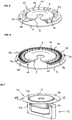
- a fluid circulator 1 of the circular type in this type of circulator we find a pump body 4 and an undulating membrane 2 this membrane being of discoidal shape.
- a first deflector 10 in the form of a ring can be seen surrounding the membrane 2 at its upstream edge 8 as well as a second deflector 10 disposed between the discharge orifice 6 and the downstream edge 9 of the membrane.
- the deflectors 10 act in the same way as those provided for the membrane 2 in the form of a longitudinal blade illustrated in figure 1 .
- At least two superposed deflectors 10 are provided upstream and/or downstream of the membrane 2 .
- the picture 3 we see represented three superimposed deflectors.
- the use of several superimposed deflectors 10 makes it possible to separate the main flow into several superimposed flows of secondary fluid and makes it possible to better channeling each of these flows in order to obtain laminar flows. This advantageous characteristic will be particularly suitable when the section of the propulsion chamber 5 at the level of the deflectors is large.
- a third type of circulator 1 is shown, namely a cylindrical circulator in which the undulating membrane 2 is of tubular shape.
- orientation means 7 are also provided in the form of cylindrical deflectors 10 arranged upstream and downstream of the membrane 2.
- the deflectors 10 are placed at a low distance from the edge of the undulating membrane 2, or from its support connecting it to the actuator, advantageously less than one fiftieth of the length separating the upstream 8 and downstream 9 edges of the undulating membrane 2.
- the first means orientation 7a is arranged at a distance from the upstream edge 8 of the membrane 2 which is less than one fiftieth of the length separating the upstream 8 and downstream 9 edges.
- the second orientation means 7b can be arranged at a distance from the downstream edge 9 of the membrane 2 which is less than one fiftieth of the length separating the upstream 8 and downstream 9 edges.
- deflectors further from the edges of the undulating membrane 2.
- FIG. 5 there is shown a variant embodiment of a circulator 1.
- this variant there are complementary orientation means 11, these orientation means complementary 11 are arranged in a plane perpendicular to a plane in which the first orientation means 7a extends and make it possible to prevent a circular displacement of the fluid between the inlet orifice 3 and the undulating membrane 2.
- complementary orientation means 11 are arranged in a plane perpendicular to a plane in which extends the second orientation means 7b and make it possible to prevent a circular displacement fluid between the discharge port and the undulating diaphragm 2.
- the complementary orientation means 11 make it possible to increase the hydraulic power of the circulator 1.
- the complementary orientation means 11 are, as shown in figure 5 , subject to the first orientation means 7a; advantageously the first orientation means 7a and the complementary orientation means 11 are formed in one piece.
- the orientation means 7a, 7b are respectively constituted by deflectors 10, however, in other embodiments, other devices may be used to orient the flow, in particular by providing two separate flow inlets, each oriented towards the top or the bottom of the membrane.
- the orientation means 7a and or 7b to comprise heat transfer elements making it possible to vary the fluidity of the fluid to be pumped and/or its temperature.
- This embodiment of the orientation means or means is shown in figure 6 with heating elements 12 carried by the first orientation means.
- complementary orientation means 11 which also fulfill the function of thermal diffusers since they extend from the orientation means carrying the heating elements 12.
- the heat transfer elements carried by the orientation 7a here include the heating means 12, but they could also include cooling means and / or a coolant transfer circuit.
- the orientation means 7 are not connected to the pump body 4 but are fixed between the drive means 13 of the membrane and the membrane 2 itself.
- the first orientation means 7a is connected via a spring effect connection to a movable part 14 of the drive means 13 to constitute an elastically deformable guide of the first orientation means with respect to the movable part 14.
- the movable part 14 By connecting an orientation means 7a or 7b via a spring-effect connection to the drive means 13 and more particularly to the movable part 14 of the drive means 13, the movable part 14 is both guided and damped by the orientation means 7a or 7b which is immersed in the fluid.
- the first orientation means 7a is obtained by a deflector 10, which is in the form of a crown, comprising at the level of the connection with the movable part 14 openings 15 giving a spring effect to the connection.
- first way orientation 7a is connected by a flexible connection 16a to the upstream edge 8 of the membrane 2, this first orientation means 7a forming with the membrane 2 and with the flexible connection 16, a sealed separation between two distinct spaces of the chamber of propulsion 5.
- the second orientation means 7b is connected by a second flexible connection 16b to the downstream edge 9 of the membrane 2, this second orientation means 7b forming with the membrane 2 and with the second flexible connection 16b, a sealed separation between two distinct spaces of the propulsion chamber 5 separated from each other by the membrane 2.
- first and second flexible connections 16a, 16b making it possible to form a seal between the part of the chamber of propulsion located above the membrane and that located below. This avoids the transverse flows of fluid between these two parts/spaces of the chamber during the displacement of the wave on the membrane 2.
Landscapes
- Engineering & Computer Science (AREA)
- Mechanical Engineering (AREA)
- General Engineering & Computer Science (AREA)
- Reciprocating Pumps (AREA)
Description
La présente invention concerne un circulateur de fluide à membrane ondulante.The present invention relates to an undulating membrane fluid circulator.
L'invention trouvera avantageusement application dans les domaines du transport de fluides fragiles, comme par exemple le médical ou l'alimentaire, toutefois bien que particulièrement prévu pour de telles applications le circulateur pourra être utilise dans d'autres applications industrielles ou domestiques.The invention will advantageously find application in the fields of the transport of fragile fluids, such as for example medical or food, however, although particularly intended for such applications, the circulator may be used in other industrial or domestic applications.
Le document
On connaît déjà du document
Ce type de circulateur comporte une membrane mise en ondulation dans un corps de pompe. Le corps de pompe définit une chambre de propulsion pour le fluide à véhiculer entre un orifice d'admission et un orifice de refoulement. La mise en action de la membrane est réalisée par des moyens d'entrainement tels qu'un actionneur, reliée à la membrane. La mise en action de la membrane provoque des ondulations de cette dernière qui transmettent une énergie mécanique au fluide de manière à assurer sa propulsion.This type of circulator comprises a membrane placed in undulation in a pump body. The pump body defines a propulsion chamber for the fluid to be conveyed between an inlet orifice and a discharge orifice. The actuation of the membrane is carried out by drive means such as an actuator, connected to the membrane. The actuation of the membrane causes undulations of the latter which transmit mechanical energy to the fluid so as to ensure its propulsion.
Ce type de circulateur présente de nombreux avantages par rapport à d'autres technologies de pompes par exemple volumétriques à cycles alternatifs ou volumétriques de type péristaltiques. Notamment, ce type de circulateur est adapté au transport de fluides fragiles et présente un encombrement réduit.This type of circulator has many advantages compared to other pump technologies, for example volumetric reciprocating cycles or volumetric peristaltic type. In particular, this type circulator is suitable for the transport of fragile fluids and has a small footprint.
Toutefois il est apparu à la demanderesse que la structure dans la demande
Plus précisément la demanderesse a constaté l'existence de mouvements du fluide dans un sens transversal au déplacement de l'onde sur la membrane. Ces mouvements transversaux, au niveau des bords de la membrane, réduisent le différentiel de pression existant dans la chambre de propulsion entre l'espace situé au dessus de la membrane et celui situé au dessous et par conséquent réduisent la force de propulsion des bords amont et aval de la membrane.More specifically, the Applicant has observed the existence of movements of the fluid in a direction transverse to the displacement of the wave on the membrane. These transverse movements, at the edges of the membrane, reduce the pressure differential existing in the propulsion chamber between the space located above the membrane and that located below and consequently reduce the propulsion force of the upstream edges and downstream of the membrane.
La présente invention a pour but de proposer un perfectionnement aux circulateurs de fluide à membrane ondulante décrits dans l'état de la technique.The object of the present invention is to propose an improvement to the undulating membrane fluid circulators described in the state of the art.
La présente invention a ainsi pour objet de proposer un circulateur dont la structure permet de conserver un différentiel de pression important au niveau des bords de la membrane assurant au circulateur une puissance hydraulique accrue pour un même encombrement.The object of the present invention is thus to provide a circulator whose structure makes it possible to maintain a significant pressure differential at the edges of the membrane, providing the circulator with increased hydraulic power for the same size.
A cet effet la présente invention concerne un circulateur de fluide à membrane ondulante selon la revendication indépendante.To this end, the present invention relates to a fluid circulator with an undulating membrane according to the independent claim.
Pour la compréhension de l'invention, l'expression « à proximité d'un des bords de la membrane ondulante » signifie « à plus grande proximité d'un des bords amont ou aval de la membrane que de l'autre des bords amont ou aval de la membrane ».For the understanding of the invention, the expression "close to one of the edges of the undulating membrane" means "closer to one of the upstream or downstream edges of the membrane than to the other of the upstream or downstream of the membrane”.
Ainsi, le premier moyen d'orientation du fluide est à plus grande proximité d'un des bords de la membrane, en l'occurrence du bord amont, qu'il ne l'est du bord aval.Thus, the first fluid orientation means is closer to one of the edges of the membrane, in this case the upstream edge, than it is to the downstream edge.
La structure du circulateur selon l'invention permet par conséquent de supprimer ou pour le moins de limiter, au niveau d'au moins un bord de la membrane, les flux transversaux de fluide au déplacement de l'onde sur la membrane.The structure of the circulator according to the invention consequently makes it possible to eliminate or at least to limit, at the level of at least one edge of the membrane, the transverse flows of fluid to the displacement of the wave on the membrane.
Idéalement, le déflecteur est une pièce distincte de la membrane qui peut être en contact contre la membrane ou qui est préférentiellement éloigné de cette membrane. Par ailleurs, ce déflecteur est préférentiellement fixé au corps de pompe.Ideally, the deflector is a part separate from the membrane which can be in contact against the membrane or which is preferentially remote from this membrane. Furthermore, this deflector is preferably fixed to the pump body.
Dans un mode de réalisation préférentiel, le premier moyen d'orientation est disposé à proximité du bord amont de la membrane ondulante et un second moyen d'orientation est disposé à proximité du bord aval de la membrane ondulante.In a preferred embodiment, the first orientation means is arranged close to the upstream edge of the undulating membrane and a second orientation means is arranged close to the downstream edge of the undulating membrane.
De la sorte la différence de pression entre l'espace situé au dessus de la membrane et celui situé au dessous est maintenue à un niveau élevé sur l'ensemble de la surface de la membrane assurant à cette dernière une puissance hydraulique accrue par rapport aux dispositifs antérieurs.In this way, the pressure difference between the space located above the membrane and that located below is maintained at a high level over the entire surface of the membrane, providing the latter with increased hydraulic power compared to the devices. previous.
On note que préférentiellement, le premier moyen d'orientation s'étend le long du bord amont tout en étant en vis-à-vis et à distance de ce bord amont.It is noted that preferentially, the first means orientation extends along the upstream edge while being opposite and at a distance from this upstream edge.
On note que préférentiellement, le deuxième moyen d'orientation s'étend le long du bord aval tout en étant en vis-à-vis et à distance de ce bord aval.It is noted that preferentially, the second orientation means extends along the downstream edge while being opposite and at a distance from this downstream edge.
Il est à noter que le premier moyen d'orientation est rigide et relativement indéformable en regard de la membrane qui est souple et déformable.It should be noted that the first orientation means is rigid and relatively non-deformable with respect to the membrane which is flexible and deformable.
De par sa rigidité, le premier moyen d'orientation favorise des écoulements laminaires de part et d'autre du moyen d'orientation jusqu'à la proximité du bord amont de la membrane, ceci réduit les turbulences au niveau du bord amont et permet une meilleure efficacité de propulsion de fluide par la membrane ondulante.Due to its rigidity, the first orientation means promotes laminar flows on either side of the orientation means up to the proximity of the upstream edge of the membrane, this reduces turbulence at the level of the upstream edge and allows better fluid propulsion efficiency by the undulating membrane.
De manière similaire, le deuxième moyen d'orientation est rigide et relativement indéformable en regard de la membrane qui est souple et déformable.Similarly, the second orientation means is rigid and relatively non-deformable opposite the membrane which is flexible and deformable.
De par sa rigidité, le deuxième moyen d'orientation favorise des écoulements laminaires de part et d'autre du moyen d'orientation, cet écoulement laminaire étant ainsi favorisé à proximité du bord aval de la membrane. Ceci réduit les turbulences au niveau du bord aval et permet une meilleure efficacité de propulsion de fluide par la membrane ondulante.Due to its rigidity, the second orientation means favors laminar flows on either side of the orientation means, this laminar flow thus being favored close to the downstream edge of the membrane. This reduces turbulence at the downstream edge and allows better fluid propulsion efficiency through the undulating membrane.
Il est aussi possible que le premier moyen d'orientation soit relié par une liaison souple au bord amont de la membrane, ce premier moyen d'orientation formant avec la membrane et avec la liaison souple une séparation étanche entre deux espaces distincts de la chambre de propulsion séparés entre eux par la membrane.It is also possible for the first orientation means to be connected by a flexible connection to the upstream edge of the membrane, this first orientation means forming with the membrane and with the flexible connection a sealed separation between two distinct spaces of the propulsion separated from each other by the membrane.
Cette liaison souple s'oppose au passage de fluide entre le premier moyen d'orientation et le bord amont de membrane, ce qui limite d'autant les sources de turbulences dans l'écoulement. Cette solution peut, dans certains cas, permettre une amélioration d'efficacité du circulateur.This flexible connection opposes the passage of fluid between the first orientation means and the upstream edge of the membrane, which accordingly limits the sources of turbulence in the flow. This solution can, in certain cases, allow an improvement in the efficiency of the circulator.
De manière similaire, il est aussi possible que le deuxième moyen d'orientation soit relié par une liaison souple au bord aval de la membrane, ce deuxième moyen d'orientation formant avec la membrane et avec cette liaison souple, une séparation étanche entre deux espaces distincts de la chambre de propulsion séparés entre eux par la membrane et le deuxième moyen d'orientation.Similarly, it is also possible for the second orientation means to be connected by a flexible connection to the downstream edge of the membrane, this second orientation means forming with the membrane and with this flexible connection, a sealed separation between two spaces distinct from the propulsion chamber separated from each other by the membrane and the second orientation means.
Cette liaison souple s'oppose au passage de fluide entre le deuxième moyen d'orientation et le bord aval de membrane, ce qui limite d'autant les sources de turbulences dans l'écoulement. Cette solution peut, dans certains cas, permettre une amélioration d'efficacité du circulateur.This flexible connection opposes the passage of fluid between the second orientation means and the downstream edge of the membrane, which accordingly limits the sources of turbulence in the flow. This solution can, in certain cases, allow an improvement in the efficiency of the circulator.
Préférentiellement, le premier moyen d'orientation comporte au moins un déflecteur qui s'étend préférentiellement le long du bord amont de la membrane et dans le prolongement de la membrane lorsque la membrane est observée selon une direction d'observation perpendiculaire à une direction d'écoulement sensiblement parallèle au déplacement de l'onde sur la membrane.Preferably, the first orientation means comprises at least one deflector which preferably extends along the upstream edge of the membrane and in the extension of the membrane when the membrane is observed in a direction of observation perpendicular to a direction of flow substantially parallel to the displacement of the wave on the membrane.
Préférentiellement, le deuxième moyen d'orientation comporte au moins un déflecteur qui s'étend préférentiellement le long du bord aval de la membrane et dans le prolongement de la membrane lorsque la membrane est observée selon une direction d'observation perpendiculaire à une direction d'écoulement sensiblement parallèle au déplacement de l'onde sur la membrane.Preferably, the second orientation means comprises at least one deflector which preferably extends along the downstream edge of the membrane and in the extension of the membrane when the membrane is observed in a direction of observation perpendicular to a direction of flow substantially parallel to the displacement of the wave on the membrane.
Ainsi, dans les cas où la membrane choisie à tendance à s'étendre dans un plan de membrane, on fera en sorte que le déflecteur amont et/ou le déflecteur aval s'étende aussi dans un plan parallèle au plan de membrane (voir les exemples des
La présente invention sera mieux comprise à la lecture d'un exemple détaillé de réalisation en référence aux dessins annexés, fournis à titre d'exemple non limitatif, parmi lesquels :
- la
figure 1 représente de manière schématique, en vue de coupe latérale, un exemple de réalisation d'un circulateur de fluide de type longitudinal réalisé selon un premier exemple ; - la
figure 2 représente de manière schématique et en coupe diamétrale partielle, un second exemple de réalisation d'un circulateur de fluide, de type circulaire ; - la
figure 3 représente de manière schématique, selon une vue en coupe partielle, un troisième exemple de réalisation d'un circulateur de fluide, de type longitudinal; - la
figure 4 représente, selon une vue en coupe partielle, un quatrième exemple de réalisation d'un circulateur de fluide, de type cylindrique; - la
figure 5 représente, en vue de perspective, une première variante de réalisation ; - la
figure 6 représente, en vue de perspective, une seconde variante de réalisation - la ;
figure 7 représente, en vue de perspective un cinquième exemple de circulateur de fluide.
- the
figure 1 shows schematically, in side sectional view, an embodiment of a longitudinal type fluid circulator produced according to a first example; - the
figure 2 shows schematically and in partial diametrical section, a second embodiment of a fluid circulator, of the circular type; - the
picture 3 - the
figure 4 represents, according to a view in partial section, a fourth embodiment of a fluid circulator, of the cylindrical type; - the
figure 5 shows, in perspective view, a first alternative embodiment; - the
figure 6 represents, in perspective view, a second alternative embodiment - the ;
figure 7 shows, in perspective view, a fifth example of a fluid circulator.
En se reportant principalement à la
La membrane ondulante 2 est associée à un moyen d'entraînement permettant un mouvement d'ondulation de la membrane 2 entre ses bords amont 8 et aval 9, ce moyen d'entraînement, ainsi que les éléments de liaison à la membrane figurent dans la demande
L'actionnement de la membrane 2 permet de créer une ondulation se propageant du bord amont 8 en direction du bord aval 9 de la membrane 2. Le fluide est quant à lui introduit par l'orifice d'admission 3 dans la chambre de propulsion 5 puis déplacé en direction de l'orifice de refoulement 6 par les ondulations de la membrane 2.The actuation of the
Pour améliorer ce transfert en direction de l'orifice de refoulement 6 on prévoit que le circulateur 1 est, selon l'invention, équipé de moyens d'orientation 7 du fluide. On voit à la
Ces moyens d'orientation 7 permettent de canaliser le flux de fluide dans une direction sensiblement parallèle au déplacement de l'onde sur la membrane 2.These orientation means 7 make it possible to channel the flow of fluid in a direction substantially parallel to the displacement of the wave on the
Le fluide, arrivant en amont de la membrane 2, est empêché par les moyens d'orientation 7 de se déplacer transversalement au déplacement de l'onde et par conséquent le fluide ne peut s'écouler en dessus ou en dessous de la membrane 2 en fonction des ondulations de cette dernière. De la sorte le différentiel de pression crée par l'ondulation n'est plus compensé par un transfert de fluide transversal comme dans le circulateur décrit dans le document
Le différentiel de pression, ainsi conservé, assure une bonne propulsion du fluide par la partie de la membrane proche du bord amont 8 qui devient par conséquent efficace. La puissance hydraulique générée par le circulateur 1 est par conséquent augmentée.The pressure differential, thus preserved, ensures good propulsion of the fluid by the part of the membrane close to the
Selon une caractéristique avantageuse de l'invention on prévoit également des moyens d'orientation 7 en aval de la membrane 2 à proximité du bord aval 9 de la membrane2.According to an advantageous characteristic of the invention, orientation means 7 are also provided downstream of the
Le fonctionnement des moyens d'orientation 7 disposés en aval est le même que celui de ceux situés en amont de la membrane 2 à savoir permettre en dirigeant le flux de fluide en sortie de membrane 2 de conserver un différentiel de pression assurant une bonne propulsion du fluide par le bord aval 9. De cette manière l'ensemble de la membrane 2 est utilisé efficacement et la puissance hydraulique du circulateur 1 est augmentée.The operation of the orientation means 7 arranged downstream is the same as that of those located upstream of the
Dans le mode de réalisation préféré illustré dans les figures annexées les moyens d'orientation 7 comportent au moins un déflecteur 10.In the preferred embodiment illustrated in the appended figures, the orientation means 7 comprise at least one
Le déflecteur 10 est avantageusement réalisé à partir d'un matériau souple, de façon à non seulement orienter le fluide mais également à favoriser sa propulsion. De manière avantageuse, on prévoit des moyens d'excitation du déflecteur souple de sorte que l'excitation du déflecteur 10 et de la membrane soient en opposition de phase.The
Cela étant dans d'autres modes de réalisation on pourra utiliser un déflecteur rigide.However, in other embodiments, a rigid deflector can be used.
De manière à optimiser la répartition du fluide par rapport à la membrane on prévoit que le ou les déflecteurs 10 soient disposés parallèle au déplacement de l'onde sur la membrane 2.In order to optimize the distribution of the fluid with respect to the membrane, provision is made for the deflector(s) 10 to be arranged parallel to the displacement of the wave on the
Cela étant, le déflecteur 10 peut également présenter une légère inclinaison pour répartir différemment le fluide entre l'espace situé au dessus de la membrane 2 et celui situé au dessous ou encore pour tenir compte de la position de l'orifice d'admission du fluide 3, ou de de celui du refoulement 6.This being the case, the
Selon un exemple qui ne fait pas partie de l'invention le déflecteur 10 est fixé, directement ou par l'intermédiaire d'éléments de liaison, au corps de pompe 4. Dans cet exemple, le déflecteur 10 et le corps de pompe peuvent être formés d'une seule pièce.According to an example which does not form part of the invention, the
En se reportant cette fois à la
Il est à noter que dans d'autres modes de réalisation on prévoit en amont et/ou en aval de la membrane 2 au moins deux déflecteurs 10 superposés. A titre d'exemple en se reportant cette fois à la
En se reportant cette fois à la
De manière à éviter un transfert du fluide entre le déflecteur amont 10 et le bord amont 8 de la membrane ondulante 2 et entre le déflecteur aval 10 et le bord aval 9 de la membrane ondulante 2, on prévoit de disposer les déflecteurs 10 à une faible distance du bord de la membrane ondulante 2, ou de son support la reliant à l'actionneur, avantageusement inférieure au cinquantième de la longueur séparant les bords amont 8 et aval 9 de la membrane ondulante 2. En d'autres termes, le premier moyen d'orientation 7a est disposé à une distance du bord amont 8 de la membrane 2 qui est inférieure au cinquantième de la longueur séparant les bords amont 8 et aval 9. De manière similaire, le second moyen d'orientation 7b peut être disposé à une distance du bord aval 9 de la membrane 2 qui est inférieure au cinquantième de la longueur séparant les bords amont 8 et aval 9.In order to avoid a transfer of the fluid between the
Cela étant, dans d'autres modes de réalisation on pourra utiliser des déflecteurs plus éloignés des bords de la membrane ondulante 2.This being so, in other embodiments it is possible to use deflectors further from the edges of the undulating
En se reportant à la
Dans un mode non illustré, on peut aussi faire en sorte que des moyens d'orientation complémentaires 11, soient disposés dans un plan perpendiculaire à un plan dans lequel s'étend le deuxième moyen d'orientation 7b et permettent d'empêcher un déplacement circulaire du fluide entre l'orifice de refoulement et la membrane ondulante 2.In a mode not illustrated, it is also possible to ensure that complementary orientation means 11 are arranged in a plane perpendicular to a plane in which extends the second orientation means 7b and make it possible to prevent a circular displacement fluid between the discharge port and the undulating
A l'instar des moyens d'orientation 7a, 7b, les moyens d'orientation complémentaires 11 permettent d'augmenter la puissance hydraulique du circulateur 1.Like the orientation means 7a, 7b, the complementary orientation means 11 make it possible to increase the hydraulic power of the
Selon une caractéristique particulière les moyens d'orientation complémentaires 11 sont, comme représentés à la
D'autres caractéristiques de l'invention auraient également pu être envisagées sans pour autant sortir du cadre de l'invention définie par les revendications ci-après.Other characteristics of the invention could also have been envisaged without thereby departing from the scope of the invention defined by the claims below.
Ainsi, à titre d'exemple, dans les différents exemples repris dans la description les moyens de d'orientation 7a, 7b sont respectivement constitués par des déflecteurs 10 toutefois dans d'autres modes de réalisation on pourra utiliser d'autres dispositifs pour orienter le flux, notamment en prévoyant deux arrivées de flux distinctes chacune orientée vers le dessus ou le dessous de la membrane.Thus, by way of example, in the various examples given in the description, the orientation means 7a, 7b are respectively constituted by
Dans un autre mode de réalisation on prévoit que les moyens d'orientations 7a et ou 7b comportent des éléments de transfert thermique permettant de faire varier la fluidité du fluide à pomper et/ou sa température. Ce mode de réalisation du ou des moyens d'orientation est représenté à la
Comme le montre la
En reliant un moyen d'orientation 7a ou 7b via une liaison à effet ressort au moyen d'entraînement 13 et plus particulièrement à la partie mobile 14 du moyen d'entraînement 13, la partie mobile 14 est à la fois guidée et amortie par le moyen d'orientation 7a ou 7b qui est plongé dans le fluide. Pour ce faire le premier moyen d'orientation 7a est obtenu par un déflecteur 10, qui est en forme de couronne, comportant au niveau de la liaison avec la partie mobile 14 des ajourages 15 donnant un effet ressort à la liaison.By connecting an orientation means 7a or 7b via a spring-effect connection to the drive means 13 and more particularly to the
Dans un autre mode de réalisation représenté à la
Dans un autre mode de réalisation représenté à la
En d'autres termes, sur le mode de réalisation représenté à la
Claims (12)
- Undulating-membrane fluid circulator comprising at least one intake port (3), a pump body (4), a propulsion chamber (5), at least one discharge port (6), and an undulating membrane (2) associated with a drive means (13) for generating an undulating movement of the membrane (2) between the upstream (8) and downstream (9) edges thereof, the undulating membrane (2) being adapted to move a fluid in the direction of the discharge port (6), wherein said circulator further comprises a first orienting means (7a) for orienting fluid disposed in the fluid propulsion chamber (5) near one of the edges (8; 9) of the undulating membrane (2) and making it possible to channel the fluid flow in a direction substantially parallel to the displacement of the wave on the membrane (2), characterized in that the first orienting means (7a) is connected to a movable portion (14) of the drive means (13) via a spring-loaded connection for providing an elastically deformable guiding of the first orienting means relative to the movable portion (14).
- Fluid circulator according to claim 1, wherein said first orienting means (7a) is disposed near the upstream edge (8) of the undulating membrane (2) and wherein a second orienting means (7b) is disposed near the downstream edge (9) of the undulating membrane (2).
- Fluid circulator according to any of claims 1 or 2, wherein the first orienting means (7a) comprises at least one baffle (10).
- Fluid circulator according to claim 2, wherein the second orienting means (7b) comprises at least one baffle (10).
- Fluid circulator according to claim 3 or claim 4, wherein said baffle (10) is flexible.
- Fluid circulator according to claim 3 or claim 4, wherein the baffle (10) is disposed substantially parallel to the displacement of the wave on the membrane (2).
- Fluid circulator according to claim 3, comprising at least two baffles (10) placed one above the other, making it possible to channel the main fluid flow into a plurality of flows that flow one above the other.
- Fluid circulator according to any of claims 1 to 6, wherein the first orienting means (7a) comprise heat transfer elements that are capable of varying the temperature of the fluid.
- Fluid circulator according to any of claims 1 to 7, wherein the first orienting means (7a) is disposed at a distance from the upstream (8) or downstream edge of the membrane (2) of less than one fiftieth of the length separating the upstream (8) and downstream (9) edges.
- Fluid circulator according to any of claims 1 to 9, comprising complementary orienting means (11) disposed in a plane perpendicular to a plane in which the first orienting means (7a) extends.
- Fluid circulator according to claim 10, wherein the complementary orienting means (11) are fastened to the first orienting means (7a).
- Fluid circulator according to claim 1, wherein the first orienting means (7a) is connected via a flexible connection (16) to the upstream edge (8) of the membrane (2), said first orienting means (7a), together with the membrane (2) and the flexible connection (16), forming a tight barrier between two different spaces of the propulsion chamber (5) separated from one another by the membrane (2).
Applications Claiming Priority (2)
| Application Number | Priority Date | Filing Date | Title |
|---|---|---|---|
| FR1760583A FR3073578B1 (en) | 2017-11-10 | 2017-11-10 | FLUID CIRCULATOR WITH RINGING MEMBRANE |
| PCT/EP2018/080749 WO2019092175A1 (en) | 2017-11-10 | 2018-11-09 | Undulating-membrane fluid circulator |
Publications (3)
| Publication Number | Publication Date |
|---|---|
| EP3707381A1 EP3707381A1 (en) | 2020-09-16 |
| EP3707381B1 true EP3707381B1 (en) | 2022-02-16 |
| EP3707381B8 EP3707381B8 (en) | 2022-03-23 |
Family
ID=60955259
Family Applications (1)
| Application Number | Title | Priority Date | Filing Date |
|---|---|---|---|
| EP18810891.4A Active EP3707381B8 (en) | 2017-11-10 | 2018-11-09 | Undulating-membrane fluid circulator |
Country Status (7)
| Country | Link |
|---|---|
| US (1) | US11512689B2 (en) |
| EP (1) | EP3707381B8 (en) |
| JP (1) | JP7158061B2 (en) |
| CN (1) | CN111433460B (en) |
| AU (1) | AU2018365313B2 (en) |
| FR (1) | FR3073578B1 (en) |
| WO (1) | WO2019092175A1 (en) |
Families Citing this family (15)
| Publication number | Priority date | Publication date | Assignee | Title |
|---|---|---|---|---|
| US10166319B2 (en) | 2016-04-11 | 2019-01-01 | CorWave SA | Implantable pump system having a coaxial ventricular cannula |
| US9968720B2 (en) | 2016-04-11 | 2018-05-15 | CorWave SA | Implantable pump system having an undulating membrane |
| WO2018178939A1 (en) | 2017-03-31 | 2018-10-04 | CorWave SA | Implantable pump system having a rectangular membrane |
| FR3073578B1 (en) | 2017-11-10 | 2019-12-13 | Corwave | FLUID CIRCULATOR WITH RINGING MEMBRANE |
| US10188779B1 (en) | 2017-11-29 | 2019-01-29 | CorWave SA | Implantable pump system having an undulating membrane with improved hydraulic performance |
| EP3938006A1 (en) | 2019-03-15 | 2022-01-19 | Corwave SA | Systems and methods for controlling an implantable blood pump |
| FR3099748B1 (en) * | 2019-08-09 | 2023-07-28 | Finx | Device for moving a watercraft |
| CN110425119A (en) * | 2019-08-21 | 2019-11-08 | 劳特士(嘉兴)机械设备有限公司 | A kind of pneumatic pump means |
| WO2021176423A1 (en) | 2020-03-06 | 2021-09-10 | CorWave SA | Implantable blood pumps comprising a linear bearing |
| FR3137658A1 (en) * | 2022-07-05 | 2024-01-12 | Finx | MULTI-DIRECTIONAL MEMBRANE FLUIDIC FLOW GENERATING DEVICE |
| WO2024105583A1 (en) | 2022-11-15 | 2024-05-23 | CorWave SA | Implantable heart pump system including an improved apical connector and/or graft connector |
| FR3144105A1 (en) * | 2022-12-23 | 2024-06-28 | Finx | system for tensioning a membrane equipping a fluid flow generator device |
| FR3144231A1 (en) * | 2022-12-23 | 2024-06-28 | Finx | HYDRAULIC PROPELLER INCLUDING AN IMMERSED ELECTRONIC BOARD |
| FR3147242A1 (en) * | 2023-03-31 | 2024-10-04 | Finx | MOBILE DEFLECTOR FOR MEMBRANE FLUID FLOW GENERATING DEVICE |
| FR3147332A1 (en) * | 2023-03-31 | 2024-10-04 | Finx | FLUID FLOW GENERATING DEVICE COMPRISING A MEMBRANE WITH DECREASING STIFFNESS |
Family Cites Families (155)
| Publication number | Priority date | Publication date | Assignee | Title |
|---|---|---|---|---|
| FR355700A (en) * | 1905-06-28 | 1905-11-09 | Leopold Selme | Turbine with undulating membranes, reversible as a pump |
| GB662047A (en) | 1949-11-21 | 1951-11-28 | George Aksel Thiberg | Improvements in diaphragm pumps and compressors |
| US2842067A (en) | 1954-10-12 | 1958-07-08 | Stevens Ronald John | Pumps for fluids, more especially liquids |
| US3107630A (en) | 1955-01-31 | 1963-10-22 | Textron Inc | Non-magnetic electro-hydraulic pump |
| US3165061A (en) | 1963-02-18 | 1965-01-12 | Edward H Smith | Method and apparatus employing acoustic energy for increasing fluid flow |
| GB1302541A (en) | 1969-02-07 | 1973-01-10 | ||
| US3608088A (en) | 1969-04-17 | 1971-09-28 | Univ Minnesota | Implantable blood pump |
| JPS5019840B1 (en) | 1970-12-30 | 1975-07-10 | ||
| US3743446A (en) | 1971-07-12 | 1973-07-03 | Atek Ind Inc | Standing wave pump |
| DE2522309C3 (en) | 1975-05-20 | 1979-10-11 | Waldemar 4500 Osnabrueck Riepe | Liquid pump |
| AU5665580A (en) | 1979-03-22 | 1980-09-25 | Wakelin, R.R.F. | Moving-wall type pump |
| US4277706A (en) | 1979-04-16 | 1981-07-07 | Nu-Tech Industries, Inc. | Actuator for heart pump |
| US4498851A (en) * | 1980-05-02 | 1985-02-12 | Piezo Electric Products, Inc. | Solid state blower |
| DE3207101C1 (en) | 1982-02-27 | 1983-10-06 | Dornier System Gmbh | Stepper motor |
| US4488854A (en) | 1982-04-12 | 1984-12-18 | Miller Richard B | Constrained wave pump |
| US4648807A (en) | 1985-05-14 | 1987-03-10 | The Garrett Corporation | Compact piezoelectric fluidic air supply pump |
| US4753221A (en) | 1986-10-22 | 1988-06-28 | Intravascular Surgical Instruments, Inc. | Blood pumping catheter and method of use |
| US4918383A (en) | 1987-01-20 | 1990-04-17 | Huff Richard E | Membrane probe with automatic contact scrub action |
| JPS63229060A (en) | 1987-03-18 | 1988-09-22 | アイシン精機株式会社 | Balloon pump in main artery |
| JPH01174278A (en) | 1987-12-28 | 1989-07-10 | Misuzu Erii:Kk | Inverter |
| US4906229A (en) | 1988-05-03 | 1990-03-06 | Nimbus Medical, Inc. | High-frequency transvalvular axisymmetric blood pump |
| US5011380A (en) | 1989-01-23 | 1991-04-30 | University Of South Florida | Magnetically actuated positive displacement pump |
| US4995857A (en) | 1989-04-07 | 1991-02-26 | Arnold John R | Left ventricular assist device and method for temporary and permanent procedures |
| US5324177A (en) | 1989-05-08 | 1994-06-28 | The Cleveland Clinic Foundation | Sealless rotodynamic pump with radially offset rotor |
| US4955856A (en) | 1989-06-30 | 1990-09-11 | Phillips Steven J | Method and apparatus for installing a ventricular assist device cannulae |
| FR2650862B1 (en) | 1989-08-11 | 1991-11-08 | Salmson Pompes | DEVICE FOR PROPELLING A FLUID |
| JPH0636821B2 (en) | 1990-03-08 | 1994-05-18 | 健二 山崎 | Implantable auxiliary artificial heart |
| DE4129970C1 (en) | 1991-09-10 | 1993-03-04 | Forschungsgesellschaft Fuer Biomedizinische Technik E.V., 5100 Aachen, De | |
| US5360445A (en) | 1991-11-06 | 1994-11-01 | International Business Machines Corporation | Blood pump actuator |
| US5982801A (en) | 1994-07-14 | 1999-11-09 | Quantum Sonic Corp., Inc | Momentum transfer apparatus |
| US5525041A (en) | 1994-07-14 | 1996-06-11 | Deak; David | Momemtum transfer pump |
| US5588812A (en) | 1995-04-19 | 1996-12-31 | Nimbus, Inc. | Implantable electric axial-flow blood pump |
| FR2744769B1 (en) * | 1996-02-12 | 1999-02-12 | Drevet Jean Baptiste | FLUID CIRCULATOR WITH VIBRATING MEMBRANE |
| US5840070A (en) | 1996-02-20 | 1998-11-24 | Kriton Medical, Inc. | Sealless rotary blood pump |
| FR2744924B1 (en) | 1996-02-21 | 1998-04-24 | Franchi Pierre | PRESSURE GENERATOR / REGULATOR DEVICE FOR AN IMPLANTABLE HEART ASSISTANCE PUMP OF THE COUNTERPRESSURE BALLOON TYPE |
| DE19613564C1 (en) | 1996-04-04 | 1998-01-08 | Guenter Prof Dr Rau | Intravascular blood pump |
| DE19625300A1 (en) | 1996-06-25 | 1998-01-02 | Guenter Prof Dr Rau | Blood pump |
| US5964694A (en) | 1997-04-02 | 1999-10-12 | Guidant Corporation | Method and apparatus for cardiac blood flow assistance |
| US6123725A (en) | 1997-07-11 | 2000-09-26 | A-Med Systems, Inc. | Single port cardiac support apparatus |
| US6532964B2 (en) | 1997-07-11 | 2003-03-18 | A-Med Systems, Inc. | Pulmonary and circulatory blood flow support devices and methods for heart surgery procedures |
| US6395026B1 (en) | 1998-05-15 | 2002-05-28 | A-Med Systems, Inc. | Apparatus and methods for beating heart bypass surgery |
| US7182727B2 (en) | 1997-07-11 | 2007-02-27 | A—Med Systems Inc. | Single port cardiac support apparatus |
| US6176822B1 (en) | 1998-03-31 | 2001-01-23 | Impella Cardiotechnik Gmbh | Intracardiac blood pump |
| US6079214A (en) | 1998-08-06 | 2000-06-27 | Face International Corporation | Standing wave pump |
| US6659740B2 (en) | 1998-08-11 | 2003-12-09 | Jean-Baptiste Drevet | Vibrating membrane fluid circulator |
| RU2143343C1 (en) | 1998-11-03 | 1999-12-27 | Самсунг Электроникс Ко., Лтд. | Microinjector and microinjector manufacture method |
| AUPQ090499A0 (en) | 1999-06-10 | 1999-07-01 | Peters, William S | Heart assist device and system |
| US6346071B1 (en) | 1999-07-16 | 2002-02-12 | World Heart Corporation | Inflow conduit assembly for a ventricular assist device |
| JP2001034568A (en) | 1999-07-21 | 2001-02-09 | Fujitsu Ltd | Logical path establishing method, and storage medium |
| DE29921352U1 (en) | 1999-12-04 | 2001-04-12 | Impella Cardiotechnik AG, 52074 Aachen | Intravascular blood pump |
| US7168138B2 (en) | 2000-03-27 | 2007-01-30 | Newfrey Llc | Resilient clip fastener |
| US6530876B1 (en) | 2000-04-25 | 2003-03-11 | Paul A. Spence | Supplemental heart pump methods and systems for supplementing blood through the heart |
| US6726648B2 (en) | 2000-08-14 | 2004-04-27 | The University Of Miami | Valved apical conduit with trocar for beating-heart ventricular assist device placement |
| DE10059714C1 (en) | 2000-12-01 | 2002-05-08 | Impella Cardiotech Ag | Intravasal pump has pump stage fitted with flexible expandible sleeve contricted during insertion through blood vessel |
| US20020095210A1 (en) | 2001-01-16 | 2002-07-18 | Finnegan Michael T. | Heart pump graft connector and system |
| US6658740B2 (en) | 2001-03-16 | 2003-12-09 | Wahl Clipper Corporation | Blade assembly for a vibrator motor |
| DE10119691A1 (en) | 2001-04-20 | 2002-11-21 | Deutsch Zentr Luft & Raumfahrt | Left ventricular assist system |
| US6723039B2 (en) | 2001-04-27 | 2004-04-20 | The Foundry, Inc. | Methods, systems and devices relating to implantable fluid pumps |
| US6493254B1 (en) | 2001-06-28 | 2002-12-10 | Intel Corporation | Current leakage reduction for loaded bit-lines in on-chip memory structures |
| AT412416B (en) * | 2001-10-23 | 2005-02-25 | Zackl Wilhelm | VALVE-FREE PUMP |
| US6672847B2 (en) | 2001-12-27 | 2004-01-06 | Pratt & Whitney Canada Corp. | Standing wave excitation cavity fluid pump |
| EP1551500A2 (en) | 2002-06-11 | 2005-07-13 | Walid Najib Aboul-Hosn | Percutaneously introduced blood pump and related methods |
| US6732501B2 (en) | 2002-06-26 | 2004-05-11 | Heartware, Inc. | Ventricular connector |
| AU2002951685A0 (en) | 2002-09-30 | 2002-10-17 | Ventrassist Pty Ltd | Physiological demand responsive control system |
| EP1644639B1 (en) | 2003-06-30 | 2009-02-11 | Nxp B.V. | Device for generating sound by means of a medium stream generated |
| FR2861910B1 (en) | 2003-10-29 | 2006-01-13 | Jean Baptiste Drevet | ELECTROMAGNETIC MACHINE WITH DEFORMABLE MEMBRANE AND ELECTROMAGNETIC MOTOR ADAPTED TO SUCH A MACHINE |
| WO2005051838A2 (en) | 2003-11-19 | 2005-06-09 | Transoma Medical, Inc. | Feedback control of ventricular assist devices |
| DE102004019721A1 (en) | 2004-03-18 | 2005-10-06 | Medos Medizintechnik Ag | pump |
| US20050261543A1 (en) | 2004-05-18 | 2005-11-24 | Yusuke Abe | Implantable artificial ventricular assist device |
| US7374565B2 (en) | 2004-05-28 | 2008-05-20 | Ethicon Endo-Surgery, Inc. | Bi-directional infuser pump with volume braking for hydraulically controlling an adjustable gastric band |
| US7108652B2 (en) | 2004-06-07 | 2006-09-19 | University Of Florida Research Foundation, Inc. | Multi-chamber self-regulating ventricular assist device |
| WO2006020273A2 (en) | 2004-07-19 | 2006-02-23 | Vascor, Inc. | Devices, systems and methods for assisting blood flow |
| WO2006020942A1 (en) | 2004-08-13 | 2006-02-23 | Delgado Reynolds M Iii | Method and apparatus for long-term assisting a left ventricle to pump blood |
| DE102004049986A1 (en) | 2004-10-14 | 2006-04-20 | Impella Cardiosystems Gmbh | Intracardiac blood pump |
| WO2007053881A1 (en) | 2005-11-08 | 2007-05-18 | Ventrassist Pty Ltd | Improvements to control systems and power systems for rotary blood pumps |
| US9144669B2 (en) | 2005-11-16 | 2015-09-29 | Heartware, Inc. | Implantation procedure for blood pumps |
| US20080232987A1 (en) | 2006-11-28 | 2008-09-25 | S.A.M. Amstar | Diaphragm circulator |
| US9744279B2 (en) | 2005-12-08 | 2017-08-29 | Heartware, Inc. | Implant connector |
| CA2636105C (en) | 2006-01-27 | 2015-05-05 | Circulite, Inc | Heart assist system |
| CN101472627B (en) | 2006-01-30 | 2013-05-08 | 国立成功大学 | Dual-pulsation bi-ventricular assist device |
| AU2013203301B2 (en) | 2006-05-31 | 2015-10-29 | Star Bp, Inc. | Heart Assist Device |
| US20070299297A1 (en) | 2006-06-26 | 2007-12-27 | Robert Jarvik | Textured conforming shell for stabilization of the interface of precision heart assist device components to tissues |
| FR2905147B1 (en) | 2006-08-25 | 2008-10-31 | Ubbink Garden B V | VIBRATORY MEMBRANE FLUID CIRCULATION PUMP. |
| US8333686B2 (en) | 2006-08-30 | 2012-12-18 | Circulite, Inc. | Cannula insertion devices, systems, and methods including a compressible member |
| US9145875B2 (en) | 2007-05-01 | 2015-09-29 | Pliant Energy Systems Llc | Ribbon transducer and pump apparatuses, methods and systems |
| US7696634B2 (en) | 2007-05-01 | 2010-04-13 | Pliant Energy Systems Llc | Pliant mechanisms for extracting power from moving fluid |
| US8432057B2 (en) | 2007-05-01 | 2013-04-30 | Pliant Energy Systems Llc | Pliant or compliant elements for harnessing the forces of moving fluid to transport fluid or generate electricity |
| JP5752413B2 (en) | 2007-06-06 | 2015-07-22 | ワールドハート コーポレイション | Wearable VAD controller with spare battery |
| US8574291B2 (en) | 2007-08-17 | 2013-11-05 | Rheinisch-Westfaelische Technische Hochschule Aachen | Linear drive and pump system, in particular an artificial heart |
| US8414603B2 (en) | 2007-09-25 | 2013-04-09 | Correx, Inc. | Applicator, assembly, and method for connecting an inlet conduit to a hollow organ |
| GB0718943D0 (en) | 2007-09-28 | 2007-11-07 | Univ Nottingham | Mechanical support |
| US8343029B2 (en) | 2007-10-24 | 2013-01-01 | Circulite, Inc. | Transseptal cannula, tip, delivery system, and method |
| US8821366B2 (en) | 2007-10-24 | 2014-09-02 | Circulite, Inc. | Transseptal cannula, tip, delivery system, and method |
| CA3017406C (en) | 2008-01-23 | 2023-08-22 | Deka Products Limited Partnership | Fluid handling cassette for use with a peritoneal dialysis system |
| CA2713865C (en) | 2008-02-08 | 2017-06-20 | Heartware, Inc. | Ventricular assist device for intraventricular placement |
| GB0813603D0 (en) | 2008-07-25 | 2008-09-03 | Cardio Carbon Technology Ltd | Ventricular assist system |
| FR2934652B1 (en) * | 2008-08-01 | 2013-01-11 | Ams R & D Sas | IMPROVED PERFORMANCE MEMBRANE PUMP WITH IMPROVED PERFORMANCE. |
| FR2934651B1 (en) * | 2008-08-01 | 2010-08-27 | Ams R & D Sas | PERFECTED ONDULATING MEMBRANE PUMP. |
| US8449444B2 (en) | 2009-02-27 | 2013-05-28 | Thoratec Corporation | Blood flow meter |
| US8366401B2 (en) | 2009-04-16 | 2013-02-05 | The Board Of Regents Of The University Of Texas Systems | Positive displacement pump system and method with rotating valve |
| US8167593B2 (en) | 2009-04-16 | 2012-05-01 | The Board Of Regents Of The University Of Texas System | System and method for pump with deformable bearing surface |
| WO2011056823A2 (en) | 2009-11-03 | 2011-05-12 | Coherex Medical, Inc. | Ventricular assist device and related methods |
| US8562508B2 (en) | 2009-12-30 | 2013-10-22 | Thoratec Corporation | Mobility-enhancing blood pump system |
| US8152845B2 (en) | 2009-12-30 | 2012-04-10 | Thoratec Corporation | Blood pump system with mounting cuff |
| DE102010009670B4 (en) | 2010-02-27 | 2013-09-19 | Knf Neuberger Gmbh | diaphragm pump |
| US9579434B2 (en) | 2010-03-03 | 2017-02-28 | The Secretary Of Atomic Energy, Govt. Of India | Flexible magnetic membrane based actuation system and devices involving the same |
| JP5898098B2 (en) | 2010-03-05 | 2016-04-06 | ミネトロニクス インコーポレイティド | Portable controller with integrated power supply for mechanical circulation assist system |
| US20110260449A1 (en) | 2010-04-21 | 2011-10-27 | Pokorney James L | Apical access and control devices |
| CA2802215A1 (en) | 2010-06-22 | 2011-12-29 | Thoratec Corporation | Apparatus and method for modifying pressure-flow characteristics of a pump |
| EP2600918B1 (en) | 2010-08-06 | 2021-10-13 | Heartware, Inc. | Conduit device for use with a ventricular assist device |
| US9227001B2 (en) | 2010-10-07 | 2016-01-05 | Everheart Systems Inc. | High efficiency blood pump |
| US8556795B2 (en) | 2010-11-23 | 2013-10-15 | Minnetronix Inc. | Portable controller with integral power source for mechanical circulation support systems |
| WO2012078873A1 (en) | 2010-12-09 | 2012-06-14 | Heartware, Inc. | Controller and power source for implantable blood pump |
| EP2662558A3 (en) | 2011-01-10 | 2015-01-14 | Benjamin Filardo | Mechanisms for creating undulating motion, such as for propulsion and for harnessing the energy of moving fluid |
| AU2012217696B2 (en) | 2011-02-16 | 2015-11-12 | Sequana Medical Nv | Apparatus and methods for treating intracorporeal fluid accumulation |
| PL218244B1 (en) | 2011-02-28 | 2014-10-31 | Fundacja Rozwoju Kardiochirurgii Im Prof Zbigniewa Religi | Blood pump, especially implantable pneumatic ventricular assist device |
| JP5502017B2 (en) | 2011-04-15 | 2014-05-28 | 株式会社テクノ高槻 | Electromagnetic vibration type diaphragm pump |
| CN103635210A (en) | 2011-05-05 | 2014-03-12 | 柏林心脏有限公司 | Blood pump |
| EP2524709A1 (en) | 2011-05-16 | 2012-11-21 | Berlin Heart GmbH | Connection system for reversible fixing of a hollow cylindrical component to a recess |
| WO2013014339A1 (en) | 2011-07-28 | 2013-01-31 | Fineheart | Removable heart pump, and method implemented in such a pump |
| CN102904448B (en) | 2011-07-29 | 2015-07-22 | 比亚迪股份有限公司 | Control chip of switch power supply and switch power supply |
| WO2013026485A1 (en) | 2011-08-25 | 2013-02-28 | Ecolab Inc. | A diaphragm pump for dosing a fluid capable of automatic degassing and an according method |
| US8821527B2 (en) | 2011-09-07 | 2014-09-02 | Circulite, Inc. | Cannula tips, tissue attachment rings, and methods of delivering and using the same |
| KR101341326B1 (en) * | 2011-12-15 | 2013-12-13 | (주)에스티아이 | Fixing apparatus for flexible thin film substrate |
| US8579790B2 (en) | 2012-01-05 | 2013-11-12 | Thoratec Corporation | Apical ring for ventricular assist device |
| US9199019B2 (en) | 2012-08-31 | 2015-12-01 | Thoratec Corporation | Ventricular cuff |
| EP2822614B1 (en) | 2012-03-05 | 2016-12-28 | Thoratec Corporation | Modular implantable medical pump |
| WO2013148697A1 (en) | 2012-03-26 | 2013-10-03 | Procyrion, Inc. | Systems and methods for fluid flows and/or pressures for circulation and perfusion enhancement |
| US9289110B2 (en) | 2012-04-05 | 2016-03-22 | Stryker Corporation | Control for surgical fluid management pump system |
| WO2013177396A2 (en) | 2012-05-24 | 2013-11-28 | Heartware, Inc. | Low-power battery pack with safety system |
| US9364596B2 (en) | 2013-01-04 | 2016-06-14 | HeartWave, Inc. | Controller and power source for implantable blood pump |
| US9398951B2 (en) | 2013-03-12 | 2016-07-26 | St. Jude Medical, Cardiology Division, Inc. | Self-actuating sealing portions for paravalvular leak protection |
| US8882477B2 (en) | 2013-03-14 | 2014-11-11 | Circulite, Inc. | Magnetically levitated and driven blood pump and method for using the same |
| WO2015085076A1 (en) | 2013-12-04 | 2015-06-11 | Heartware, Inc. | Molded vad |
| EP3131600B1 (en) | 2014-04-15 | 2021-06-16 | Tc1 Llc | Methods and systems for providing battery feedback to patient |
| CN110101927B (en) | 2014-04-15 | 2021-10-08 | Tc1有限责任公司 | Method and system for controlling a blood pump |
| FR3021074B1 (en) | 2014-05-14 | 2016-05-27 | Saint Gobain Performance Plastics France | MEMBRANE PUMP |
| CN106456854B (en) | 2014-05-20 | 2019-05-31 | 瑟柯莱特公司 | Heart assist system and method |
| US9526819B2 (en) | 2014-09-26 | 2016-12-27 | Ch Biomedical (Usa), Inc. | Ventricular assist device controller with integrated power source |
| EP3256185B1 (en) | 2015-02-12 | 2019-10-30 | Tc1 Llc | System and method for controlling the position of a levitated rotor |
| FR3032917B1 (en) * | 2015-02-20 | 2017-02-17 | Valeo Systemes Thermiques | AIR CONDITIONING MODULE OF A MOTOR VEHICLE |
| WO2016179262A1 (en) | 2015-05-04 | 2016-11-10 | Yeoman & Company | Hand tool handle assembly and method of manufacture |
| EP3115616B1 (en) | 2015-07-06 | 2022-09-07 | Levitronix GmbH | Electromagnetic rotary drive |
| EP3377136B1 (en) | 2015-11-20 | 2020-05-06 | Tc1 Llc | Energy management of blood pump controllers |
| EP3377135B1 (en) | 2015-11-20 | 2020-05-06 | Tc1 Llc | Blood pump controllers having daisy-chained batteries |
| WO2017161317A1 (en) | 2016-03-18 | 2017-09-21 | Everheart Systems Inc. | Cardiac connection for ventricular assist device |
| US10166319B2 (en) | 2016-04-11 | 2019-01-01 | CorWave SA | Implantable pump system having a coaxial ventricular cannula |
| US9968720B2 (en) | 2016-04-11 | 2018-05-15 | CorWave SA | Implantable pump system having an undulating membrane |
| FR3054861B1 (en) | 2016-08-02 | 2019-08-23 | Zodiac Aerotechnics | METHOD OF CONTROLLING AN ONDULATING MEMBRANE PUMP, AND PILOT SYSTEM OF AN INJUSTING MEMBRANE PUMP |
| WO2018039124A1 (en) | 2016-08-22 | 2018-03-01 | Tc1 Llc | Heart pump cuff |
| WO2018178939A1 (en) | 2017-03-31 | 2018-10-04 | CorWave SA | Implantable pump system having a rectangular membrane |
| FR3073578B1 (en) | 2017-11-10 | 2019-12-13 | Corwave | FLUID CIRCULATOR WITH RINGING MEMBRANE |
| US10188779B1 (en) | 2017-11-29 | 2019-01-29 | CorWave SA | Implantable pump system having an undulating membrane with improved hydraulic performance |
| WO2020115607A2 (en) | 2018-12-05 | 2020-06-11 | CorWave SA | Apparatus and methods for coupling a blood pump to the heart |
| EP3938006A1 (en) | 2019-03-15 | 2022-01-19 | Corwave SA | Systems and methods for controlling an implantable blood pump |
-
2017
- 2017-11-10 FR FR1760583A patent/FR3073578B1/en active Active
-
2018
- 2018-11-09 AU AU2018365313A patent/AU2018365313B2/en active Active
- 2018-11-09 EP EP18810891.4A patent/EP3707381B8/en active Active
- 2018-11-09 CN CN201880078891.9A patent/CN111433460B/en active Active
- 2018-11-09 JP JP2020525986A patent/JP7158061B2/en active Active
- 2018-11-09 US US16/762,909 patent/US11512689B2/en active Active
- 2018-11-09 WO PCT/EP2018/080749 patent/WO2019092175A1/en unknown
Also Published As
| Publication number | Publication date |
|---|---|
| EP3707381A1 (en) | 2020-09-16 |
| FR3073578A1 (en) | 2019-05-17 |
| US20210172429A1 (en) | 2021-06-10 |
| WO2019092175A1 (en) | 2019-05-16 |
| CN111433460B (en) | 2022-10-04 |
| JP2021502513A (en) | 2021-01-28 |
| AU2018365313A1 (en) | 2020-05-21 |
| US11512689B2 (en) | 2022-11-29 |
| EP3707381B8 (en) | 2022-03-23 |
| FR3073578B1 (en) | 2019-12-13 |
| AU2018365313B2 (en) | 2024-05-09 |
| CN111433460A (en) | 2020-07-17 |
| JP7158061B2 (en) | 2022-10-21 |
Similar Documents
| Publication | Publication Date | Title |
|---|---|---|
| EP3707381B1 (en) | Undulating-membrane fluid circulator | |
| EP3859135B1 (en) | Turbine engine for aircraft provided with a thermoacoustic system | |
| EP2740905B1 (en) | Splitter of an axial turbomachine, corresponding compressor and axial turbomachine | |
| EP1969232B1 (en) | Diaphragm circulator | |
| EP2756252B1 (en) | Heat transfer device using capillary pumping | |
| EP2352922A1 (en) | Diffuser having blades with apertures | |
| EP2430314B1 (en) | Double exhaust centrifugal pump | |
| EP3465043B1 (en) | Air manifold and vehicle comprising said air manifold | |
| EP3869993B1 (en) | Hairstyling appliance having a liquid evacuation device | |
| EP3640467B1 (en) | Turbine engine provided with a thermoacoustic system | |
| EP2879955B1 (en) | Air inlet for helicopter engine with increased circumferential intake lips | |
| EP3452772B1 (en) | Plastic heat exchanger and vehicle comprising this exchanger | |
| FR3087855A1 (en) | A CENTRIFUGAL TURBOCHARGER HAVING A GAS FLOW PATH HAVING A RELAXATION CHAMBER | |
| FR3079605A1 (en) | PLATE HEAT EXCHANGER HAVING A FLOW DISTRIBUTION SHIELD FOR A TURBOMOTEUR FLUID | |
| EP3027995B1 (en) | Evaporator with non-return device for diphasic loop | |
| EP3482148B1 (en) | Heat exchanger and vehicle comprising said exchanger | |
| FR3115333A1 (en) | Piston for cryogenic fluid pump | |
| FR2931901A1 (en) | ACOUSTICAL ATTENUATION DEVICE FOR THE INTAKE LINE OF A THERMAL MOTOR, AND ADMISSION LINE INCORPORATING IT. | |
| FR3099525A1 (en) | Thermal management system | |
| WO2024200306A1 (en) | Movable deflector for a membrane device for generating a fluid flow | |
| FR2914978A1 (en) | Four way valve for motor vehicle, has body delimiting chamber in which inlet ducts and outlet ducts open, and flap extending across chamber to close former inlet duct and latter outlet duct in derivation position | |
| EP3054168B1 (en) | Device for circulating a gas in a closed circuit | |
| EP2006631A1 (en) | Collector flange for a heat exchanger | |
| FR3035167A1 (en) | PURGE SOLENOID VALVE FOR VAPOR EXHAUST DEVICE | |
| FR2962515A1 (en) | Fluidic connector for connecting e.g. bags, has set of male and female connection end fittings that are respectively connected to another set of female and male connection end fittings at coupled state of elements |
Legal Events
| Date | Code | Title | Description |
|---|---|---|---|
| STAA | Information on the status of an ep patent application or granted ep patent |
Free format text: STATUS: UNKNOWN |
|
| STAA | Information on the status of an ep patent application or granted ep patent |
Free format text: STATUS: THE INTERNATIONAL PUBLICATION HAS BEEN MADE |
|
| PUAI | Public reference made under article 153(3) epc to a published international application that has entered the european phase |
Free format text: ORIGINAL CODE: 0009012 |
|
| STAA | Information on the status of an ep patent application or granted ep patent |
Free format text: STATUS: REQUEST FOR EXAMINATION WAS MADE |
|
| 17P | Request for examination filed |
Effective date: 20200604 |
|
| AK | Designated contracting states |
Kind code of ref document: A1 Designated state(s): AL AT BE BG CH CY CZ DE DK EE ES FI FR GB GR HR HU IE IS IT LI LT LU LV MC MK MT NL NO PL PT RO RS SE SI SK SM TR |
|
| AX | Request for extension of the european patent |
Extension state: BA ME |
|
| DAV | Request for validation of the european patent (deleted) | ||
| DAX | Request for extension of the european patent (deleted) | ||
| STAA | Information on the status of an ep patent application or granted ep patent |
Free format text: STATUS: EXAMINATION IS IN PROGRESS |
|
| 17Q | First examination report despatched |
Effective date: 20210305 |
|
| GRAP | Despatch of communication of intention to grant a patent |
Free format text: ORIGINAL CODE: EPIDOSNIGR1 |
|
| STAA | Information on the status of an ep patent application or granted ep patent |
Free format text: STATUS: GRANT OF PATENT IS INTENDED |
|
| INTG | Intention to grant announced |
Effective date: 20211007 |
|
| GRAS | Grant fee paid |
Free format text: ORIGINAL CODE: EPIDOSNIGR3 |
|
| GRAA | (expected) grant |
Free format text: ORIGINAL CODE: 0009210 |
|
| STAA | Information on the status of an ep patent application or granted ep patent |
Free format text: STATUS: THE PATENT HAS BEEN GRANTED |
|
| GRAT | Correction requested after decision to grant or after decision to maintain patent in amended form |
Free format text: ORIGINAL CODE: EPIDOSNCDEC |
|
| AK | Designated contracting states |
Kind code of ref document: B1 Designated state(s): AL AT BE BG CH CY CZ DE DK EE ES FI FR GB GR HR HU IE IS IT LI LT LU LV MC MK MT NL NO PL PT RO RS SE SI SK SM TR |
|
| REG | Reference to a national code |
Ref country code: GB Ref legal event code: FG4D Free format text: NOT ENGLISH |
|
| REG | Reference to a national code |
Ref country code: CH Ref legal event code: PK Free format text: RECTIFICATION B8 Ref country code: CH Ref legal event code: EP |
|
| RAP4 | Party data changed (patent owner data changed or rights of a patent transferred) |
Owner name: CORWAVE SA |
|
| REG | Reference to a national code |
Ref country code: DE Ref legal event code: R096 Ref document number: 602018030982 Country of ref document: DE |
|
| REG | Reference to a national code |
Ref country code: AT Ref legal event code: REF Ref document number: 1469038 Country of ref document: AT Kind code of ref document: T Effective date: 20220315 |
|
| RAP4 | Party data changed (patent owner data changed or rights of a patent transferred) |
Owner name: CORWAVE SA |
|
| REG | Reference to a national code |
Ref country code: IE Ref legal event code: FG4D Free format text: LANGUAGE OF EP DOCUMENT: FRENCH |
|
| REG | Reference to a national code |
Ref country code: LT Ref legal event code: MG9D |
|
| REG | Reference to a national code |
Ref country code: NL Ref legal event code: MP Effective date: 20220216 |
|
| REG | Reference to a national code |
Ref country code: AT Ref legal event code: MK05 Ref document number: 1469038 Country of ref document: AT Kind code of ref document: T Effective date: 20220216 |
|
| PG25 | Lapsed in a contracting state [announced via postgrant information from national office to epo] |
Ref country code: SE Free format text: LAPSE BECAUSE OF FAILURE TO SUBMIT A TRANSLATION OF THE DESCRIPTION OR TO PAY THE FEE WITHIN THE PRESCRIBED TIME-LIMIT Effective date: 20220216 Ref country code: RS Free format text: LAPSE BECAUSE OF FAILURE TO SUBMIT A TRANSLATION OF THE DESCRIPTION OR TO PAY THE FEE WITHIN THE PRESCRIBED TIME-LIMIT Effective date: 20220216 Ref country code: PT Free format text: LAPSE BECAUSE OF FAILURE TO SUBMIT A TRANSLATION OF THE DESCRIPTION OR TO PAY THE FEE WITHIN THE PRESCRIBED TIME-LIMIT Effective date: 20220616 Ref country code: NO Free format text: LAPSE BECAUSE OF FAILURE TO SUBMIT A TRANSLATION OF THE DESCRIPTION OR TO PAY THE FEE WITHIN THE PRESCRIBED TIME-LIMIT Effective date: 20220516 Ref country code: NL Free format text: LAPSE BECAUSE OF FAILURE TO SUBMIT A TRANSLATION OF THE DESCRIPTION OR TO PAY THE FEE WITHIN THE PRESCRIBED TIME-LIMIT Effective date: 20220216 Ref country code: LT Free format text: LAPSE BECAUSE OF FAILURE TO SUBMIT A TRANSLATION OF THE DESCRIPTION OR TO PAY THE FEE WITHIN THE PRESCRIBED TIME-LIMIT Effective date: 20220216 Ref country code: HR Free format text: LAPSE BECAUSE OF FAILURE TO SUBMIT A TRANSLATION OF THE DESCRIPTION OR TO PAY THE FEE WITHIN THE PRESCRIBED TIME-LIMIT Effective date: 20220216 Ref country code: ES Free format text: LAPSE BECAUSE OF FAILURE TO SUBMIT A TRANSLATION OF THE DESCRIPTION OR TO PAY THE FEE WITHIN THE PRESCRIBED TIME-LIMIT Effective date: 20220216 Ref country code: BG Free format text: LAPSE BECAUSE OF FAILURE TO SUBMIT A TRANSLATION OF THE DESCRIPTION OR TO PAY THE FEE WITHIN THE PRESCRIBED TIME-LIMIT Effective date: 20220516 |
|
| PG25 | Lapsed in a contracting state [announced via postgrant information from national office to epo] |
Ref country code: PL Free format text: LAPSE BECAUSE OF FAILURE TO SUBMIT A TRANSLATION OF THE DESCRIPTION OR TO PAY THE FEE WITHIN THE PRESCRIBED TIME-LIMIT Effective date: 20220216 Ref country code: LV Free format text: LAPSE BECAUSE OF FAILURE TO SUBMIT A TRANSLATION OF THE DESCRIPTION OR TO PAY THE FEE WITHIN THE PRESCRIBED TIME-LIMIT Effective date: 20220216 Ref country code: GR Free format text: LAPSE BECAUSE OF FAILURE TO SUBMIT A TRANSLATION OF THE DESCRIPTION OR TO PAY THE FEE WITHIN THE PRESCRIBED TIME-LIMIT Effective date: 20220517 Ref country code: FI Free format text: LAPSE BECAUSE OF FAILURE TO SUBMIT A TRANSLATION OF THE DESCRIPTION OR TO PAY THE FEE WITHIN THE PRESCRIBED TIME-LIMIT Effective date: 20220216 Ref country code: AT Free format text: LAPSE BECAUSE OF FAILURE TO SUBMIT A TRANSLATION OF THE DESCRIPTION OR TO PAY THE FEE WITHIN THE PRESCRIBED TIME-LIMIT Effective date: 20220216 |
|
| PG25 | Lapsed in a contracting state [announced via postgrant information from national office to epo] |
Ref country code: IS Free format text: LAPSE BECAUSE OF FAILURE TO SUBMIT A TRANSLATION OF THE DESCRIPTION OR TO PAY THE FEE WITHIN THE PRESCRIBED TIME-LIMIT Effective date: 20220617 |
|
| PG25 | Lapsed in a contracting state [announced via postgrant information from national office to epo] |
Ref country code: SM Free format text: LAPSE BECAUSE OF FAILURE TO SUBMIT A TRANSLATION OF THE DESCRIPTION OR TO PAY THE FEE WITHIN THE PRESCRIBED TIME-LIMIT Effective date: 20220216 Ref country code: SK Free format text: LAPSE BECAUSE OF FAILURE TO SUBMIT A TRANSLATION OF THE DESCRIPTION OR TO PAY THE FEE WITHIN THE PRESCRIBED TIME-LIMIT Effective date: 20220216 Ref country code: RO Free format text: LAPSE BECAUSE OF FAILURE TO SUBMIT A TRANSLATION OF THE DESCRIPTION OR TO PAY THE FEE WITHIN THE PRESCRIBED TIME-LIMIT Effective date: 20220216 Ref country code: EE Free format text: LAPSE BECAUSE OF FAILURE TO SUBMIT A TRANSLATION OF THE DESCRIPTION OR TO PAY THE FEE WITHIN THE PRESCRIBED TIME-LIMIT Effective date: 20220216 Ref country code: DK Free format text: LAPSE BECAUSE OF FAILURE TO SUBMIT A TRANSLATION OF THE DESCRIPTION OR TO PAY THE FEE WITHIN THE PRESCRIBED TIME-LIMIT Effective date: 20220216 Ref country code: CZ Free format text: LAPSE BECAUSE OF FAILURE TO SUBMIT A TRANSLATION OF THE DESCRIPTION OR TO PAY THE FEE WITHIN THE PRESCRIBED TIME-LIMIT Effective date: 20220216 |
|
| REG | Reference to a national code |
Ref country code: DE Ref legal event code: R097 Ref document number: 602018030982 Country of ref document: DE |
|
| PG25 | Lapsed in a contracting state [announced via postgrant information from national office to epo] |
Ref country code: AL Free format text: LAPSE BECAUSE OF FAILURE TO SUBMIT A TRANSLATION OF THE DESCRIPTION OR TO PAY THE FEE WITHIN THE PRESCRIBED TIME-LIMIT Effective date: 20220216 |
|
| PLBE | No opposition filed within time limit |
Free format text: ORIGINAL CODE: 0009261 |
|
| STAA | Information on the status of an ep patent application or granted ep patent |
Free format text: STATUS: NO OPPOSITION FILED WITHIN TIME LIMIT |
|
| 26N | No opposition filed |
Effective date: 20221117 |
|
| PG25 | Lapsed in a contracting state [announced via postgrant information from national office to epo] |
Ref country code: SI Free format text: LAPSE BECAUSE OF FAILURE TO SUBMIT A TRANSLATION OF THE DESCRIPTION OR TO PAY THE FEE WITHIN THE PRESCRIBED TIME-LIMIT Effective date: 20220216 |
|
| P01 | Opt-out of the competence of the unified patent court (upc) registered |
Effective date: 20230316 |
|
| PG25 | Lapsed in a contracting state [announced via postgrant information from national office to epo] |
Ref country code: MC Free format text: LAPSE BECAUSE OF FAILURE TO SUBMIT A TRANSLATION OF THE DESCRIPTION OR TO PAY THE FEE WITHIN THE PRESCRIBED TIME-LIMIT Effective date: 20220216 |
|
| REG | Reference to a national code |
Ref country code: CH Ref legal event code: PL |
|
| REG | Reference to a national code |
Ref country code: BE Ref legal event code: MM Effective date: 20221130 |
|
| PG25 | Lapsed in a contracting state [announced via postgrant information from national office to epo] |
Ref country code: LI Free format text: LAPSE BECAUSE OF NON-PAYMENT OF DUE FEES Effective date: 20221130 Ref country code: IT Free format text: LAPSE BECAUSE OF FAILURE TO SUBMIT A TRANSLATION OF THE DESCRIPTION OR TO PAY THE FEE WITHIN THE PRESCRIBED TIME-LIMIT Effective date: 20220216 Ref country code: CH Free format text: LAPSE BECAUSE OF NON-PAYMENT OF DUE FEES Effective date: 20221130 |
|
| PG25 | Lapsed in a contracting state [announced via postgrant information from national office to epo] |
Ref country code: LU Free format text: LAPSE BECAUSE OF NON-PAYMENT OF DUE FEES Effective date: 20221109 |
|
| PG25 | Lapsed in a contracting state [announced via postgrant information from national office to epo] |
Ref country code: IE Free format text: LAPSE BECAUSE OF NON-PAYMENT OF DUE FEES Effective date: 20221109 |
|
| PG25 | Lapsed in a contracting state [announced via postgrant information from national office to epo] |
Ref country code: BE Free format text: LAPSE BECAUSE OF NON-PAYMENT OF DUE FEES Effective date: 20221130 |
|
| PGFP | Annual fee paid to national office [announced via postgrant information from national office to epo] |
Ref country code: DE Payment date: 20230912 Year of fee payment: 6 |
|
| PG25 | Lapsed in a contracting state [announced via postgrant information from national office to epo] |
Ref country code: CY Free format text: LAPSE BECAUSE OF FAILURE TO SUBMIT A TRANSLATION OF THE DESCRIPTION OR TO PAY THE FEE WITHIN THE PRESCRIBED TIME-LIMIT Effective date: 20220216 |
|
| PG25 | Lapsed in a contracting state [announced via postgrant information from national office to epo] |
Ref country code: MK Free format text: LAPSE BECAUSE OF FAILURE TO SUBMIT A TRANSLATION OF THE DESCRIPTION OR TO PAY THE FEE WITHIN THE PRESCRIBED TIME-LIMIT Effective date: 20220216 Ref country code: HU Free format text: LAPSE BECAUSE OF FAILURE TO SUBMIT A TRANSLATION OF THE DESCRIPTION OR TO PAY THE FEE WITHIN THE PRESCRIBED TIME-LIMIT; INVALID AB INITIO Effective date: 20181109 |
|
| PG25 | Lapsed in a contracting state [announced via postgrant information from national office to epo] |
Ref country code: TR Free format text: LAPSE BECAUSE OF FAILURE TO SUBMIT A TRANSLATION OF THE DESCRIPTION OR TO PAY THE FEE WITHIN THE PRESCRIBED TIME-LIMIT Effective date: 20220216 |
|
| PG25 | Lapsed in a contracting state [announced via postgrant information from national office to epo] |
Ref country code: MT Free format text: LAPSE BECAUSE OF FAILURE TO SUBMIT A TRANSLATION OF THE DESCRIPTION OR TO PAY THE FEE WITHIN THE PRESCRIBED TIME-LIMIT Effective date: 20220216 |
|
| PGFP | Annual fee paid to national office [announced via postgrant information from national office to epo] |
Ref country code: GB Payment date: 20240919 Year of fee payment: 7 |
|
| PGFP | Annual fee paid to national office [announced via postgrant information from national office to epo] |
Ref country code: FR Payment date: 20240909 Year of fee payment: 7 |