EP2600918B1 - Conduit device for use with a ventricular assist device - Google Patents
Conduit device for use with a ventricular assist device Download PDFInfo
- Publication number
- EP2600918B1 EP2600918B1 EP11815382.4A EP11815382A EP2600918B1 EP 2600918 B1 EP2600918 B1 EP 2600918B1 EP 11815382 A EP11815382 A EP 11815382A EP 2600918 B1 EP2600918 B1 EP 2600918B1
- Authority
- EP
- European Patent Office
- Prior art keywords
- heart
- pump
- conduit device
- valve
- inflow tube
- Prior art date
- Legal status (The legal status is an assumption and is not a legal conclusion. Google has not performed a legal analysis and makes no representation as to the accuracy of the status listed.)
- Active
Links
- 230000002861 ventricular Effects 0.000 title description 4
- 239000007943 implant Substances 0.000 claims description 34
- 239000008280 blood Substances 0.000 claims description 22
- 210000004369 blood Anatomy 0.000 claims description 22
- 239000000463 material Substances 0.000 claims description 12
- 230000008467 tissue growth Effects 0.000 claims description 9
- 230000001737 promoting effect Effects 0.000 claims description 6
- 230000012010 growth Effects 0.000 claims description 3
- 239000004753 textile Substances 0.000 claims description 3
- RTAQQCXQSZGOHL-UHFFFAOYSA-N Titanium Chemical compound [Ti] RTAQQCXQSZGOHL-UHFFFAOYSA-N 0.000 claims description 2
- 239000004005 microsphere Substances 0.000 claims description 2
- 239000010936 titanium Substances 0.000 claims description 2
- 229910052719 titanium Inorganic materials 0.000 claims description 2
- 210000001519 tissue Anatomy 0.000 description 16
- 238000000034 method Methods 0.000 description 12
- 238000002513 implantation Methods 0.000 description 10
- 210000005003 heart tissue Anatomy 0.000 description 8
- 238000009958 sewing Methods 0.000 description 7
- 238000003780 insertion Methods 0.000 description 5
- 230000037431 insertion Effects 0.000 description 5
- 210000005240 left ventricle Anatomy 0.000 description 5
- 230000017531 blood circulation Effects 0.000 description 4
- 206010052428 Wound Diseases 0.000 description 3
- 208000027418 Wounds and injury Diseases 0.000 description 3
- 239000000853 adhesive Substances 0.000 description 3
- 230000001070 adhesive effect Effects 0.000 description 3
- 238000005086 pumping Methods 0.000 description 3
- 238000001356 surgical procedure Methods 0.000 description 3
- 210000000709 aorta Anatomy 0.000 description 2
- 230000000740 bleeding effect Effects 0.000 description 2
- 230000010102 embolization Effects 0.000 description 2
- 230000035876 healing Effects 0.000 description 2
- 230000003993 interaction Effects 0.000 description 2
- 229920004934 Dacron® Polymers 0.000 description 1
- 241000124008 Mammalia Species 0.000 description 1
- 210000003484 anatomy Anatomy 0.000 description 1
- 210000002376 aorta thoracic Anatomy 0.000 description 1
- 238000013459 approach Methods 0.000 description 1
- 230000001174 ascending effect Effects 0.000 description 1
- 238000005452 bending Methods 0.000 description 1
- 210000005242 cardiac chamber Anatomy 0.000 description 1
- 230000002612 cardiopulmonary effect Effects 0.000 description 1
- 210000000748 cardiovascular system Anatomy 0.000 description 1
- 238000013461 design Methods 0.000 description 1
- 201000010099 disease Diseases 0.000 description 1
- 208000037265 diseases, disorders, signs and symptoms Diseases 0.000 description 1
- 230000002526 effect on cardiovascular system Effects 0.000 description 1
- 230000000694 effects Effects 0.000 description 1
- 239000004744 fabric Substances 0.000 description 1
- 210000003709 heart valve Anatomy 0.000 description 1
- 230000023597 hemostasis Effects 0.000 description 1
- 229920001903 high density polyethylene Polymers 0.000 description 1
- 239000004700 high-density polyethylene Substances 0.000 description 1
- 208000015181 infectious disease Diseases 0.000 description 1
- 208000014674 injury Diseases 0.000 description 1
- 239000012528 membrane Substances 0.000 description 1
- 229910052751 metal Inorganic materials 0.000 description 1
- 239000002184 metal Substances 0.000 description 1
- 150000002739 metals Chemical class 0.000 description 1
- 238000012986 modification Methods 0.000 description 1
- 230000004048 modification Effects 0.000 description 1
- 239000004033 plastic Substances 0.000 description 1
- 229920003023 plastic Polymers 0.000 description 1
- 239000005020 polyethylene terephthalate Substances 0.000 description 1
- 229920000139 polyethylene terephthalate Polymers 0.000 description 1
- 230000002035 prolonged effect Effects 0.000 description 1
- 210000001147 pulmonary artery Anatomy 0.000 description 1
- 238000007789 sealing Methods 0.000 description 1
- 239000013589 supplement Substances 0.000 description 1
- 230000008733 trauma Effects 0.000 description 1
- 230000002792 vascular Effects 0.000 description 1
- 230000029663 wound healing Effects 0.000 description 1
Images


Classifications
-
- A—HUMAN NECESSITIES
- A61—MEDICAL OR VETERINARY SCIENCE; HYGIENE
- A61M—DEVICES FOR INTRODUCING MEDIA INTO, OR ONTO, THE BODY; DEVICES FOR TRANSDUCING BODY MEDIA OR FOR TAKING MEDIA FROM THE BODY; DEVICES FOR PRODUCING OR ENDING SLEEP OR STUPOR
- A61M60/00—Blood pumps; Devices for mechanical circulatory actuation; Balloon pumps for circulatory assistance
- A61M60/80—Constructional details other than related to driving
- A61M60/855—Constructional details other than related to driving of implantable pumps or pumping devices
- A61M60/861—Connections or anchorings for connecting or anchoring pumps or pumping devices to parts of the patient's body
- A61M60/863—Apex rings
-
- A—HUMAN NECESSITIES
- A61—MEDICAL OR VETERINARY SCIENCE; HYGIENE
- A61M—DEVICES FOR INTRODUCING MEDIA INTO, OR ONTO, THE BODY; DEVICES FOR TRANSDUCING BODY MEDIA OR FOR TAKING MEDIA FROM THE BODY; DEVICES FOR PRODUCING OR ENDING SLEEP OR STUPOR
- A61M60/00—Blood pumps; Devices for mechanical circulatory actuation; Balloon pumps for circulatory assistance
- A61M60/10—Location thereof with respect to the patient's body
- A61M60/122—Implantable pumps or pumping devices, i.e. the blood being pumped inside the patient's body
- A61M60/165—Implantable pumps or pumping devices, i.e. the blood being pumped inside the patient's body implantable in, on, or around the heart
- A61M60/178—Implantable pumps or pumping devices, i.e. the blood being pumped inside the patient's body implantable in, on, or around the heart drawing blood from a ventricle and returning the blood to the arterial system via a cannula external to the ventricle, e.g. left or right ventricular assist devices
-
- A—HUMAN NECESSITIES
- A61—MEDICAL OR VETERINARY SCIENCE; HYGIENE
- A61M—DEVICES FOR INTRODUCING MEDIA INTO, OR ONTO, THE BODY; DEVICES FOR TRANSDUCING BODY MEDIA OR FOR TAKING MEDIA FROM THE BODY; DEVICES FOR PRODUCING OR ENDING SLEEP OR STUPOR
- A61M60/00—Blood pumps; Devices for mechanical circulatory actuation; Balloon pumps for circulatory assistance
- A61M60/20—Type thereof
- A61M60/205—Non-positive displacement blood pumps
- A61M60/216—Non-positive displacement blood pumps including a rotating member acting on the blood, e.g. impeller
- A61M60/226—Non-positive displacement blood pumps including a rotating member acting on the blood, e.g. impeller the blood flow through the rotating member having mainly radial components
- A61M60/232—Centrifugal pumps
-
- A—HUMAN NECESSITIES
- A61—MEDICAL OR VETERINARY SCIENCE; HYGIENE
- A61M—DEVICES FOR INTRODUCING MEDIA INTO, OR ONTO, THE BODY; DEVICES FOR TRANSDUCING BODY MEDIA OR FOR TAKING MEDIA FROM THE BODY; DEVICES FOR PRODUCING OR ENDING SLEEP OR STUPOR
- A61M60/00—Blood pumps; Devices for mechanical circulatory actuation; Balloon pumps for circulatory assistance
- A61M60/20—Type thereof
- A61M60/205—Non-positive displacement blood pumps
- A61M60/216—Non-positive displacement blood pumps including a rotating member acting on the blood, e.g. impeller
- A61M60/237—Non-positive displacement blood pumps including a rotating member acting on the blood, e.g. impeller the blood flow through the rotating member having mainly axial components, e.g. axial flow pumps
-
- A—HUMAN NECESSITIES
- A61—MEDICAL OR VETERINARY SCIENCE; HYGIENE
- A61M—DEVICES FOR INTRODUCING MEDIA INTO, OR ONTO, THE BODY; DEVICES FOR TRANSDUCING BODY MEDIA OR FOR TAKING MEDIA FROM THE BODY; DEVICES FOR PRODUCING OR ENDING SLEEP OR STUPOR
- A61M60/00—Blood pumps; Devices for mechanical circulatory actuation; Balloon pumps for circulatory assistance
- A61M60/80—Constructional details other than related to driving
- A61M60/855—Constructional details other than related to driving of implantable pumps or pumping devices
- A61M60/89—Valves
-
- A—HUMAN NECESSITIES
- A61—MEDICAL OR VETERINARY SCIENCE; HYGIENE
- A61M—DEVICES FOR INTRODUCING MEDIA INTO, OR ONTO, THE BODY; DEVICES FOR TRANSDUCING BODY MEDIA OR FOR TAKING MEDIA FROM THE BODY; DEVICES FOR PRODUCING OR ENDING SLEEP OR STUPOR
- A61M60/00—Blood pumps; Devices for mechanical circulatory actuation; Balloon pumps for circulatory assistance
- A61M60/10—Location thereof with respect to the patient's body
- A61M60/122—Implantable pumps or pumping devices, i.e. the blood being pumped inside the patient's body
- A61M60/126—Implantable pumps or pumping devices, i.e. the blood being pumped inside the patient's body implantable via, into, inside, in line, branching on, or around a blood vessel
- A61M60/148—Implantable pumps or pumping devices, i.e. the blood being pumped inside the patient's body implantable via, into, inside, in line, branching on, or around a blood vessel in line with a blood vessel using resection or like techniques, e.g. permanent endovascular heart assist devices
-
- A—HUMAN NECESSITIES
- A61—MEDICAL OR VETERINARY SCIENCE; HYGIENE
- A61M—DEVICES FOR INTRODUCING MEDIA INTO, OR ONTO, THE BODY; DEVICES FOR TRANSDUCING BODY MEDIA OR FOR TAKING MEDIA FROM THE BODY; DEVICES FOR PRODUCING OR ENDING SLEEP OR STUPOR
- A61M60/00—Blood pumps; Devices for mechanical circulatory actuation; Balloon pumps for circulatory assistance
- A61M60/80—Constructional details other than related to driving
- A61M60/855—Constructional details other than related to driving of implantable pumps or pumping devices
- A61M60/89—Valves
- A61M60/894—Passive valves, i.e. valves actuated by the blood
Definitions
- the present invention relates to components and methods used in connection with ventricular assist device and interaction with the anatomy of a human, namely the heart and blood flood therethrough.
- the heart lacks sufficient pumping capacity to meet the needs of the body.
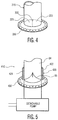
- This inadequacy can be alleviated by providing a mechanical pump referred to herein as a heart pump or a ventricular assist device ("VAD"), one example of which is illustrated in FIG. 6 , to supplement the pumping action of the heart.
- VAD ventricular assist device
- Considerable effort has been devoted to providing a VAD which can be implanted and which can remain in operation for months or years to keep the patient alive while the heart heals, or which can remain in operation permanently during the patient's lifetime if the heart does not heal, or which can keep the patient alive until a suitable donor heart becomes available.
- the VAD is typically connected to the heart, most commonly to the left ventricle. Typically, one end of an outflow tube is connected to the VAD and the other end is connected to the aorta. Once connected, the VAD and the heart both pump blood from the left ventricle to the ascending or descending aorta to improve blood flow. Alternatively, a VAD may be connected to the ventricle to assist the heart in pumping blood into pulmonary arteries.
- the VAD 82 typically is connected to the heart through the use of a sewing ring or a VAD connector 50 (see FIG. 6 ), as disclosed in U.S. Published Patent Application Nos. 2004/0171905 and 2007/0134993 .
- the VAD connector may be in the shape of a ring and is attached to the outer surface of the heart, commonly through the use of sutures.
- a separate surgical tool is then used to cut or core a hole in the ventricle centered within the VAD connector.
- An inflow tube 84 ( FIG. 6 ) extending from the VAD is inserted through the hole in the left ventricle.
- the VAD is then attached to the VAD connector such that the inflow tube 84 of the VAD is positioned within the central opening of the VAD connector 50.
- the VAD connector is used to clamp the inflow tube and thereby hold the VAD in position relative to the heart and form a seal around the inflow tube.
- such connectors and configurations can potentially cause problems when the VAD is removed and/or replaced with a new VAD.
- the heart wall, and related tissues heal around the VAD structure. Once the VAD requires replacement, and the VAD structure is separated from the healed tissue, the risk of renewed bleeding or embolization may occur.
- the healing process must recur, risking infection, prolonged bleeding, or other complications.
- An additional drawback to the current configurations, of above, is that, during initial placement of the VAD or replacement of the VAD, the opening in the heart wall is open and thus blood from the heart may exit from the opening.
- the patient may be subjected to cardioplegia (temporary stoppage of the heart), cardiopulmonary bypass, or both during implantation of the VAD, during removal of the VAD, or during implantation of a replacement VAD.
- cardioplegia temporary stoppage of the heart
- cardiopulmonary bypass or both during implantation of the VAD, during removal of the VAD, or during implantation of a replacement VAD.
- this hole in the heart wall may allow the inflow, through the hole and into the heart, of outside air, which can also cause complications for the patient.
- a new device capable of securing a VAD to heart tissue, or other cardiovascular tissue, while alleviating or eliminating many of the issues above, is needed.
- Document US 2008/0076959 A1 describes a blood circulation assist system comprising an inflow cannula having a lumen and an insertion device configured to be received therein and to facilitate insertion of a portion of the inflow cannula into a heart chamber.
- Document GB 2343121 A discloses an implantable blood pump apparatus which can be implanted using standard vascular grafts for the inlet and outlet.
- the inlet cannula may be connected to the left ventricular apex (in parallel) in which case both the inlet and outlet cannulae can have integral valves.
- a conduit is designed to be placed within a wall of a heart, such as through a prepared opening or hole in the heart wall.
- the conduit is hollow and extends to form a sleeve over an inflow tube of the heart pump, such as a VAD, which traverses the heart wall and enters a chamber of the heart.
- the conduit provides for a simplified and noninvasive approach to removal and/or replacement of the heart pump.
- the present invention includes a conduit device adapted for placement within a wall of a heart, comprising a hollow generally cylindrical body having an interior bore including a valve therein, the interior bore and the valve being adapted for engagement with an inflow tube of a heart pump therethrough, and having an exterior surface comprising a tissue-growth promoting material adapted to promote growth of tissue on the exterior surface.
- the conduit device may be adapted to be fixedly connected to an implant connector, and the implant connector may be adapted for removable engagement with the heart pump.
- the conduit device may be substantially cylindrical, or may include a taper along at least a portion of the length.
- the body may have a leading end adapted for positioning within the heart, the device further may include a coring projection extending from the leading end of the body.
- the valve may be fixedly secured within the interior bore of the conduit device and may have an open position in which the valve occludes the bore and a closed position in which the valve does not occlude the bore.
- the valve may be a one-way valve and include a plurality of closure elements resiliently biased towards one another, and further the body may be adapted to engage the inflow tube of the pump so that the inflow tube projects between the closure elements. These closure elements may form a seal around the inflow tube of the pump when the inflow tube is received in the bore and through the valve.
- the conduit device may be secured to the wall of the heart by a VAD connector and an at least one length of suture.
- the conduit device may be secured to the wall of the heart by a flange and an at least one length of suture.
- the conduit device may be secured to the wall of the heart by a sewing ring and an at least one length of suture.
- the body may have a leading end adapted for placement within the heart and a trailing end, and the body may be adapted to engage a portion of the pump so that the portion of the pump may extend into the bore from the trailing end.
- a conduit device may be adapted for placement within a wall of a heart, comprising a hollow generally cylindrical body, having an interior bore and a valve, the body being adapted for engagement with an inflow tube extending from a heart pump, through the bore and the valve, and to a chamber of the heart, wherein the valve is adapted to minimize blood flow out of the heart and the conduit device is adapted to be fixedly connected to an implant connector, and the implant connector is adapted for removable engagement with the heart pump.
- the conduit body includes a tissue-growth promoting material.
- the inflow tube may have a length which is longer than the length of the conduit device.
- the present invention may include a device for assisting the flow of blood through at least a portion of a heart, the device comprising the combination of a heart pump and a conduit device of any of the disclosed embodiments, a portion of the heart pump may be engaged with the interior bore of the conduit device.
- the portion of the heart pump is an inflow tube extending from the pump, through the interior bore, and to a chamber of the heart.
- the inflow tube may further have a length which is longer than the length of the conduit device.
- the portion of the heart pump may be a body of an axial flow pump.
- the device may further include an implant connector, wherein the conduit device may be fixedly connected to the implant connector, and the implant connector may be removably engaged with the heart pump.
- the implant connector may be a flange, a VAD connector, a sewing ring, or any combination thereof.
- a method for treating a heart condition may comprise accessing a portion of a wall of a heart, through either open surgery or arthroscopic methods, positioning a conduit device through an access hole through the heart wall, securing the conduit device to the heart wall, inserting a portion of a heart pump through the conduit device, and releasably securing the heart pump to the conduit device.
- the method may further include the step of removing the heart pump by accessing the implant site, releasing the heart pump from the implant connector and conduit device, and removing the heart pump from the heart and conduit device.
- the method may then further include the step of inserting a portion of a new heart pump through the conduit device, and releasably securing the new heart pump to the conduit device using the implant connector.
- the method may include implanting a plug within the conduit device to substantially seal the interior bore of the conduit device.
- a conduit device 10 includes a hollow body 15 which defines an interior bore 16.
- Device 10 may further include at least one of a valve 20 and an implant connector, such as flange 30.
- the device 10 is dimensioned to be positioned adjacent to, or within, the heart.
- device 10 may be positioned within a prepared hole through the wall of the heart which creates a passageway from the outside of the heart and into at least one of the chambers of the heart, such as the left ventricle. While this positioning of device 10 will be the exemplary location in the below embodiments, it is envisioned that device 10 may be used in other locations within the cardiovascular system of a mammal where a heart pump or other such device is in need.
- the hollow body 15, defining interior bore 16 therethrough, has a generally cylindrical shape along its length.
- Body 15 is adapted for engagement with an inflow tube of a heart pump, such as an inflow tube (for example, illustrated as inflow tube 84 in FIG. 6 ) which may be positioned within the interior bore 16 (see FIG. 7 ).
- the body 15 has a leading portion 18 and a trailing portion 19.
- the leading portion 18 is adapted to be positioned within the heart, while the trailing portion 19 is adapted to be positioned at or adjacent to a wall of the heart and secured to both an inflow tube of the heart pump and to an outer surface of the heart wall optionally using, for example, an implant connector such as flange 30.
- the body 15 may include an outer surface 17 capable of promoting tissue growth, or a neo-intimal linking, along at least a portion of the length of the body 15.
- the tissue-growth may be limited to only the outer surface 17 of body 15, such that the interior bore 16 is substantially protected from tissue in-growth. This may also protect structures positioned within bore 16 from tissue in-growth. Such limited in-growth may be accomplished by forming a growth-promoting layer or material on the outer surface 17, with a substantially impermeable underlayer beneath the growth-promoting layer.
- the tissue-growth promoting layer or material may include, for example, a texture suitable for tissue in-growth created by sintered titanium microspheres, or by the application of a textile such as Dacron® PET.
- the impermeable layer may be any material capable of substantially preventing tissue in-growth, such as high-density polyethylene or the like, as is known in the art.
- the growth-promoting layer of the conduit device 10 may be adapted to promote wound healing at the contact area of the wall of the heart and the outer surface 17, though, the growth promoting layer may extend along any portion of the length of body 15.
- the tissue in-growth at the contact area of the wall of the heart and the outer surface 17 may provide additional stability to the secure connection between body 15 and the heart wall. This stable connection may promote hemostasis and may decrease the risk of embolization at the wound site, particularly during removal and/or replacement of the heart pump.
- the body 15 may be rigid or pliable, depending on the intended use of the device 10. For example, if the device 10 is intended for placement through a heart wall, the body 15 may have a certain degree of pliablility such that the body 15 is capable of expanding, contracting, and bending due to the movement of the heart and heart wall as the heart beats. Such a pliable structure may also provide for a better seal between the body 15 and the inflow tube of the heart pump within the interior bore 16.
- the diameter of the interior bore 16 may be substantially the same, or slightly smaller than, the diameter of the inflow tube of the heart pump, such that insertion of the inflow tube of the heart pump into the interior bore 16 causes the body 15 to expand, which may then create a force exerted by the body 15 to return to its original diameter.
- Such elasticity of the body 15 may result in a better seal between the body and the inflow tube of the heart pump within the interior bore.
- the body 15 may generally be constructed of a textile or other fabric material, such as braided polymeric filaments. Suitable materials for a rigid body 15 may be high density plastics and/or metals.
- Device 10 may also include an implant connector, such as flange 30, which may be fixedly positioned on or adjacent to the trailing portion 19 of body 15 such that trailing portion 19 of device 10 can further securely engage to, for example, a heart pump or a VAD connector (see FIG. 6 ).
- the flange 30 may be secured to the body 15 through a suture, an adhesive, or the like, or may be formed or woven along with the body itself, as a unitary structure.
- the implant connector may alternatively be a typical sewing ring or the VAD connector itself, either of which may be secured to the body 15 using a suture, adhesive, or the like.
- the implant connector fixedly secures the body 15 to tissue, such as at the contact area with the wall of the heart, using at least one length of suture using, for example, suture throughholes 31 as on flange 30, though such throughholes may also be present on the sewing ring or VAD connector, if used.
- the implant connector may further provide for removable engagement with the VAD.
- the device 10 and implant connector remain engaged to the heart, while the heart pump is removable therefrom.
- suture throughholes 31 may also be used to secure flange 30 to the VAD connector in addition to the heart tissue.
- the VAD connector may also be fixedly secured to the flange 30, such that the body 15 with flange 30, along with the VAD connector, is held in place in the heart by the flange sutured to the heart tissue, as well as by the tissue in-growth, while the heart pump is removable therefrom.
- the device 10 further includes a valve 20 positioned within the interior bore 16 of body 15.
- the valve 20 is fixedly secured to the interior of the body 15 such that the valve 20 remains in position even when, for example, blood or inflow tube 84 passes through the interior bore 16 and contacts valve 20.
- valve 20 may be sewn to the interior of body 15, or alternatively, an adhesive may be used, or the like.
- valve 20 and body 15 may also be manufactured as a single, continuous structure.
- Valve 20 includes at least an open position in which the valve occludes the bore and a closed position in which the valve does not occlude the bore.
- Valve 20 may be a one-way valve and may include a plurality of closure elements 21, 22 resiliently biased towards one another such that they allow blood, an inflow tube 84, or the like to pass in one direction but prevent blood from traveling in the other direction.
- the resilient bias of the closure elements may, for example, engage the inflow tube 84 of the heart pump so that the inflow tube projects between the closure elements and the closure elements create a tight connection to substantially seal around the inflow tube to substantially prevent leakage, as illustrated in FIG. 5 , for example.
- the valve may include more than just two closure elements 21, 22, and may have three or more elements, all of which function similar to elements 21, 22.
- the valve 20 may substantially prevent the flow of blood from the heart via the body 15.
- the valve 20 may be any type of valve suitable for the above purposes.
- FIGS. 1 and 5 illustrate valves having three-dimensional closure elements similar in design to a natural heart valve or similar one-way type valve. Alternative embodiments of valves suitable for use in the conduit device are also disclosed below, though it is envisioned that other shapes and types of one-way valves may also be incorporated.
- FIG. 7 illustrates a further embodiment of a device for assisting the flow of blood through at least a portion of the heart including the combination of a heart pump 82 and a conduit 10 similar to conduit 10 of FIG. 1 , though the implant connector is VAD connector 50 rather than flange 30.
- flange 30 may also be included to engage the body 15, heart wall and VAD connector 50 to one another (or, a sewing ring may replace the VAD connector and/or the flange).
- valve 20 has been removed for clarity, though in this combination the valve would be substantially open and the closure elements 21, 22 would be adjacent to an inner surface of the interior bore 16.
- an inflow tube 84 of the heart pump 82 is positioned within the interior bore 16 of body 15 such that, if body 15 is secured through a heart wall, the inflow tube extends from the distal end 19 of the body 15, through the body 15, and into the heart, such as a chamber of the heart.
- the length of the inflow tube 84 may be longer than the body 15, such that it extends further into the heart than the body 15.
- the pump may be removeably secured to the wall of the heart through VAD connector 50, and the VAD connector is in turn fixedly secured to both the body 15 and the wall of the heart (see FIG. 8 ).
- FIG. 8 illustrates this embodiment in position on the wall of the heart, with inflow tube 84 protruding into the left ventricle.
- the heart wall, body 15, and VAD connector 50 are all secured to one another, through the use of an at least one length of suture, and VAD connector 50 and heart pump 82 are releasably secured to one another.
- the conduit device 10 provides for a more manageable connection between the heart pump and the heart tissue.
- the conduit provides an intermediate layer between the heart tissue and the heart pump, thus minimizing possible interaction between the heart pump and heart tissue during removal or replacement of the heart pump.
- the present invention may also include an embodiment of a method for treating a heart condition, which includes accessing a portion of a wall of a heart, through either open surgery or arthroscopic methods, positioning a conduit device 10 through an access hole through the heart wall, securing the conduit device 10 to the heart wall, inserting an inflow tube of a heart pump through the conduit device, and releasably securing the heart pump to the conduit device.
- the access hole through the heart wall may be created prior to positioning the conduit device through the hole, or in conjunction with positioning the conduit device through the hole.
- the device is secured to the heart wall by, for example, suturing the implant connector of the device 10 to an outer surface of the heart wall adjacent to the access hole. Further, such securing of the device may allow tissue growth to occur between adjacent heart wall tissue and the outer surface 17 of the conduit device 10, and possibly on the implant connector itself.
- the heart pump may be positioned within the conduit device.
- the heart pump includes an inflow tube 84, which is inserted into the conduit device 10 such that it passes through the device and enters into the inner volume of a chamber of the heart.
- the heart pump is then releasably secured to the conduit device using the implant connector such as, for example, the VAD connector 50, a flange and/or a sewing ring.
- the implant connector such as, for example, the VAD connector 50, a flange and/or a sewing ring.
- the VAD connector 50 is fixedly secured to the device 10 and the heart wall, and the heart pump is releasably secured to the VAD connector 50.
- the method may further include the step of removing the heart pump, once the heart pump is no longer working properly or no longer needed, by accessing the implant site, releasing the heart pump from the implant connector and conduit device, and removing the heart pump from the heart and conduit device.
- the method may then further include the step of inserting an inflow tube of a new heart pump through the conduit device, and releasably securing the new heart pump to the conduit device using the implant connector.
- VAD connector 50 is loosened or unlocked from its connection to the heart pump, namely to inflow tube 84, and the heart pump and inflow tube are withdrawn from the device 10.
- Device 10 remains in place through the heart wall.
- the valve (not shown) closes within the interior bore of the conduit and prevents backflow of blood out of the device 10.
- a new pump with a new inflow tube is then implanted in similar manner, by placing inflow tube through device 10, causing valve 20 to re-open, and tightening VAD connector 50 onto the new pump.
- This step may be replicated as necessary as the conduit device minimizes possible trauma to the heart tissue by the removal and replacement of heart pumps into the heart.
- the conduit device may remain in the heart tissue and a plug of suitable geometry may be placed within the device 10 to prevent leakage of blood through the conduit device.
- the plug may fill substantially the entire length of the interior bore, or may only fill one end of the conduit device.
- valve into the device 10 may limit the need for bypass during such a surgical method because the blood will not flow out of the device due to the one way valve, thus substantially reducing, if not all together eliminating, the need for the patient to be placed on bypass during implantation of the device 10.
- bypass may be utilized if desired.
- the valve may also reduce the need for de-airing, or alternatively simplifying the de-airing process, the pump prior to final implantation because the valve may limit the amount of air in the device 10, and therefore limit the amount of air present in the device 10 upon exposure to air during implantation or replacement of a pump. Such limitation of exposure also may reduce possible complications associated with such exposure. Previously, a surgeon would have had to de-air a larger volume because, during pump replacement, the interior of the heart was open to the atmosphere. The device 10, however, includes a valve which limits the exposure of the interior of the heart to the outside atmosphere.
- FIGS. 2A and 2B illustrate another embodiment of the conduit device 110, in which the leading end 118 of the body 115 is capable of being positioned within the heart, and further includes a coring projection 111 extending therefrom.
- Coring projection 111 may be used to implant the device 110, such as by coring a hole through the wall of the heart, through which the body 115 will be secured. The resulting core is removed from the heart wall by retrieving the core through the interior bore 116 of the body 115 using an appropriate instrument.
- the leading end 118 of body 115 may be smooth, or be of a non-cutting shape, and a separate coring device may be positioned through the interior bore 116, or may be inserted through the heart wall prior to the insertion of the device 110.
- coring projection 111 may simplify this type of surgery by limiting the number of instruments necessary for implantation of the device 110.
- the resulting hole through the heart wall may be substantially the same size as the outer diameter of body 115, or may be slightly smaller than this outer diameter, to ensure a tight, substantially sealed fit. Such a tight fit may minimize leaking between the tissue wound and the body 115, and may further promote healing of the tissue wound. Additionally, combining the coring and implantation of the device into a single step may provide improved accuracy in alignment of the device 110 with the hole in the heart wall.
- Coring projection 111 may be used in conjunction with a valve, such as valve 120 illustrated as a "duck-bill" shaped valve which may include two elongated, pliable closure elements capable of substantially sealing around an inflow tube of a heart pump, additional instrumentation, or other such structure, positioned through the valve.
- a core capturing instrument (not shown) would be positioned through valve 120 to the leading end 118 of the body 115, in order to capture the core after it has been cut by coring projection 111.
- a separate coring instrument may be placed within bore 116, and through valve 120. The valve 120 would substantially seal around any instrument passing therethrough until the core and instrument are removed from valve 120, causing the valve 120 to close and seal the bore 116 thus preventing blood from exiting the heart.
- FIGS. 3A and 3B illustrate a further embodiment of the conduit device 210 which includes a hollow body 215 having a substantially cylindrical shape along at least a portion 219 of its length, and the remaining portion 218 of its length having a substantially conical shape.
- the body 215 may be expandable to accommodate an inflow tube 84 from a heart pump therethrough. Therefore, in this embodiment, the leading end of the substantially conical portion 218 of the body 215 may be adapted to act as a valve 220, such that the leading end of the conical portion is substantially closed, as in FIG. 3A to prevent backflow of blood from the heart.
- the leading end expands around the inflow tube, as in FIG. 3B .
- the elasticity of conical portion 218 may prevent leakage between the conical portion and the inflow tube due to the tendency of the conical portion 218 to contract back to its original shape with a smaller diameter, thus forming a tight, sealed fit between the body 215 and inflow tube 84.
- FIG. 4 illustrates yet another embodiment of a valve for use in the conduit device.
- Valve 320 is a substantially flat valve which may include a membrane with a slit therethrough, forming elements 321 and 322.
- the slit may include an overlap of material which may maintain a seal, during periods of back pressure from the blood coming from the heart and entering the interior bore of the body, by preventing elements 321 and 322 from inverting.
- a device for assisting the flow of blood through at least a portion of the heart includes the combination of a detachable heart pump and a conduit 410.
- the conduit includes valve 420 (shown in cross-section) and an implant connector (flange 430), but the body of conduit 410 only has a length substantially the width of the flange 430.
- the conduit is positioned essentially only on the outer wall of the heart, and secured thereto.
- conduit 410 is an access doorway for a pump to gain access to the interior of the heart, while still providing a layer between the inflow tube of the heart pump and the heart wall at the opening in the heart wall.
- the inflow tube 84 of the pump is then placed through the valve, thus pushing elements 421 and 422 away from their original position, and the inflow tube 84 thus passes into the heart.
- elements 421 and 422 may have a bias towards returning to their original position, and thus may press against the outside surface of inflow tube 84 to provide a seal to inhibit leakage. It may be desirable to prevent tissue growth on the valve 420 itself, and thus the valve may be constructed of a suitable material to prevent tissue in-growth on the valve itself.
- the inflow tube may also include a valve 85, similar to those disclosed herein, to assist in preventing leakage during pump detachment.
- the body of the conduit device may itself act as the inflow tube of the heart pump, such that the trailing end of the body attaches directly to the pump body, or separate VAD connector (if present), and the blood flows directly through the interior bore of the body, without an inflow tube of the pump being present.
- the body of the conduit device would be releasably secured to the pump body at its trailing end through the separate VAD connector or alternatively through a press-fit or other connection with the heart pump.
- the inner surface of the interior bore of the body may be of a material, or include suitable treatment, to prevent the in-growth of tissue, or further to prevent adhesion of blood onto its surface.
- the pump may be an axial flow pump (not shown), which is sized to be positioned substantially completely within the interior bore of the conduit device body.
- the pump itself may pass through the bore, through a valve (if present), and a portion may pass into the interior of the heart.
- a pump may not have an inflow tube, and instead the pump itself would be secured within the interior bore using, for example, a connector between the trailing end of the body of the conduit device and the axial flow pump.
- a plug may instead be placed within the interior bore of the body.
- the plug may also be used to replace the heart pump if it is no longer needed or if it is removed for a period of time.
- One such plug is disclosed in U.S. Published Application No. 2009/0171136 .
- the plug may be secured to the implant connector and/or the body of the conduit device.
Description
- This application claims priority of
U.S. Provisional Application No. 61/401,033 WO 2012/019126) filed August 6, 2010 . - The present invention relates to components and methods used in connection with ventricular assist device and interaction with the anatomy of a human, namely the heart and blood flood therethrough.
- In certain disease states, the heart lacks sufficient pumping capacity to meet the needs of the body. This inadequacy can be alleviated by providing a mechanical pump referred to herein as a heart pump or a ventricular assist device ("VAD"), one example of which is illustrated in
FIG. 6 , to supplement the pumping action of the heart. Considerable effort has been devoted to providing a VAD which can be implanted and which can remain in operation for months or years to keep the patient alive while the heart heals, or which can remain in operation permanently during the patient's lifetime if the heart does not heal, or which can keep the patient alive until a suitable donor heart becomes available. - The VAD is typically connected to the heart, most commonly to the left ventricle. Typically, one end of an outflow tube is connected to the VAD and the other end is connected to the aorta. Once connected, the VAD and the heart both pump blood from the left ventricle to the ascending or descending aorta to improve blood flow. Alternatively, a VAD may be connected to the ventricle to assist the heart in pumping blood into pulmonary arteries.
- The VAD 82 typically is connected to the heart through the use of a sewing ring or a VAD connector 50 (see
FIG. 6 ), as disclosed inU.S. Published Patent Application Nos. 2004/0171905 and2007/0134993 . The VAD connector may be in the shape of a ring and is attached to the outer surface of the heart, commonly through the use of sutures. A separate surgical tool is then used to cut or core a hole in the ventricle centered within the VAD connector. An inflow tube 84 (FIG. 6 ) extending from the VAD is inserted through the hole in the left ventricle. The VAD is then attached to the VAD connector such that theinflow tube 84 of the VAD is positioned within the central opening of theVAD connector 50. The VAD connector is used to clamp the inflow tube and thereby hold the VAD in position relative to the heart and form a seal around the inflow tube. - However, such connectors and configurations can potentially cause problems when the VAD is removed and/or replaced with a new VAD. For example, upon implantation of a VAD, using the above configurations, the heart wall, and related tissues, heal around the VAD structure. Once the VAD requires replacement, and the VAD structure is separated from the healed tissue, the risk of renewed bleeding or embolization may occur. Moreover, upon implantation of the new VAD, the healing process must recur, risking infection, prolonged bleeding, or other complications.
- An additional drawback to the current configurations, of above, is that, during initial placement of the VAD or replacement of the VAD, the opening in the heart wall is open and thus blood from the heart may exit from the opening. To avoid massive blood loss, the patient may be subjected to cardioplegia (temporary stoppage of the heart), cardiopulmonary bypass, or both during implantation of the VAD, during removal of the VAD, or during implantation of a replacement VAD. Moreover, this hole in the heart wall may allow the inflow, through the hole and into the heart, of outside air, which can also cause complications for the patient.
- For at least these reasons, a new device capable of securing a VAD to heart tissue, or other cardiovascular tissue, while alleviating or eliminating many of the issues above, is needed.
- Document
US 2008/0076959 A1 describes a blood circulation assist system comprising an inflow cannula having a lumen and an insertion device configured to be received therein and to facilitate insertion of a portion of the inflow cannula into a heart chamber. - Document
GB 2343121 A - The invention is defined by the appended claims. In one example, a conduit is designed to be placed within a wall of a heart, such as through a prepared opening or hole in the heart wall. The conduit is hollow and extends to form a sleeve over an inflow tube of the heart pump, such as a VAD, which traverses the heart wall and enters a chamber of the heart. The conduit provides for a simplified and noninvasive approach to removal and/or replacement of the heart pump.
- In an embodiment, the present invention includes a conduit device adapted for placement within a wall of a heart, comprising a hollow generally cylindrical body having an interior bore including a valve therein, the interior bore and the valve being adapted for engagement with an inflow tube of a heart pump therethrough, and having an exterior surface comprising a tissue-growth promoting material adapted to promote growth of tissue on the exterior surface.
- Further, the conduit device may be adapted to be fixedly connected to an implant connector, and the implant connector may be adapted for removable engagement with the heart pump. The conduit device may be substantially cylindrical, or may include a taper along at least a portion of the length. Additionally, the body may have a leading end adapted for positioning within the heart, the device further may include a coring projection extending from the leading end of the body.
- Moreover, the valve may be fixedly secured within the interior bore of the conduit device and may have an open position in which the valve occludes the bore and a closed position in which the valve does not occlude the bore. In one example, the valve may be a one-way valve and include a plurality of closure elements resiliently biased towards one another, and further the body may be adapted to engage the inflow tube of the pump so that the inflow tube projects between the closure elements. These closure elements may form a seal around the inflow tube of the pump when the inflow tube is received in the bore and through the valve.
- In one example, the conduit device may be secured to the wall of the heart by a VAD connector and an at least one length of suture. In another example, the conduit device may be secured to the wall of the heart by a flange and an at least one length of suture. In yet another example, the conduit device may be secured to the wall of the heart by a sewing ring and an at least one length of suture.
- Moreover, the body may have a leading end adapted for placement within the heart and a trailing end, and the body may be adapted to engage a portion of the pump so that the portion of the pump may extend into the bore from the trailing end.
- In an example, a conduit device may be adapted for placement within a wall of a heart, comprising a hollow generally cylindrical body, having an interior bore and a valve, the body being adapted for engagement with an inflow tube extending from a heart pump, through the bore and the valve, and to a chamber of the heart, wherein the valve is adapted to minimize blood flow out of the heart and the conduit device is adapted to be fixedly connected to an implant connector, and the implant connector is adapted for removable engagement with the heart pump.
- Further, the conduit body includes a tissue-growth promoting material. Also, the inflow tube may have a length which is longer than the length of the conduit device.
- In another embodiment, the present invention may include a device for assisting the flow of blood through at least a portion of a heart, the device comprising the combination of a heart pump and a conduit device of any of the disclosed embodiments, a portion of the heart pump may be engaged with the interior bore of the conduit device.
- The portion of the heart pump is an inflow tube extending from the pump, through the interior bore, and to a chamber of the heart. The inflow tube may further have a length which is longer than the length of the conduit device. Alternatively, the portion of the heart pump may be a body of an axial flow pump. The device may further include an implant connector, wherein the conduit device may be fixedly connected to the implant connector, and the implant connector may be removably engaged with the heart pump. The implant connector may be a flange, a VAD connector, a sewing ring, or any combination thereof.
- In an example, a method for treating a heart condition may comprise accessing a portion of a wall of a heart, through either open surgery or arthroscopic methods, positioning a conduit device through an access hole through the heart wall, securing the conduit device to the heart wall, inserting a portion of a heart pump through the conduit device, and releasably securing the heart pump to the conduit device. The method may further include the step of removing the heart pump by accessing the implant site, releasing the heart pump from the implant connector and conduit device, and removing the heart pump from the heart and conduit device. The method may then further include the step of inserting a portion of a new heart pump through the conduit device, and releasably securing the new heart pump to the conduit device using the implant connector. Alternatively, once the heart pump has been removed, the method may include implanting a plug within the conduit device to substantially seal the interior bore of the conduit device.
-
-
FIG. 1 illustrates one embodiment of a conduit device of the present invention. -
FIGS. 2A and 2B illustrate another embodiment of a conduit device of the present invention, whereinFIG. 2A shows a valve in a closed position andFIG. 2B shows the valve in an open position with an inflow tube from a heart pump positioned therethrough. -
FIGS. 3A and 3B illustrate a further embodiment of a conduit device of the present invention. -
FIG. 4 illustrates an alternative embodiment of a valve of a conduit device of the present invention. -
FIG. 5 illustrates one embodiment of a combination of a conduit device and a heart pump having an inflow tube. -
FIG. 6 illustrates one example of a heart pump, or VAD, known in the prior art. -
FIG. 7 illustrates yet another embodiment of a combination of one embodiment of a conduit device of the present invention and the heart pump ofFIG. 6 . -
FIG. 8 illustrates the placement of the combination ofFIG. 7 through a wall of a heart. - In one embodiment, as illustrated in
FIG. 1 , aconduit device 10 includes ahollow body 15 which defines aninterior bore 16.Device 10 may further include at least one of avalve 20 and an implant connector, such asflange 30. Thedevice 10 is dimensioned to be positioned adjacent to, or within, the heart. For example,device 10 may be positioned within a prepared hole through the wall of the heart which creates a passageway from the outside of the heart and into at least one of the chambers of the heart, such as the left ventricle. While this positioning ofdevice 10 will be the exemplary location in the below embodiments, it is envisioned thatdevice 10 may be used in other locations within the cardiovascular system of a mammal where a heart pump or other such device is in need. - The
hollow body 15, defining interior bore 16 therethrough, has a generally cylindrical shape along its length.Body 15 is adapted for engagement with an inflow tube of a heart pump, such as an inflow tube (for example, illustrated asinflow tube 84 inFIG. 6 ) which may be positioned within the interior bore 16 (seeFIG. 7 ). Thebody 15 has a leadingportion 18 and a trailingportion 19. The leadingportion 18 is adapted to be positioned within the heart, while the trailingportion 19 is adapted to be positioned at or adjacent to a wall of the heart and secured to both an inflow tube of the heart pump and to an outer surface of the heart wall optionally using, for example, an implant connector such asflange 30. - The
body 15 may include anouter surface 17 capable of promoting tissue growth, or a neo-intimal linking, along at least a portion of the length of thebody 15. The tissue-growth, however, may be limited to only theouter surface 17 ofbody 15, such that the interior bore 16 is substantially protected from tissue in-growth. This may also protect structures positioned withinbore 16 from tissue in-growth. Such limited in-growth may be accomplished by forming a growth-promoting layer or material on theouter surface 17, with a substantially impermeable underlayer beneath the growth-promoting layer. The tissue-growth promoting layer or material may include, for example, a texture suitable for tissue in-growth created by sintered titanium microspheres, or by the application of a textile such as Dacron® PET. The impermeable layer may be any material capable of substantially preventing tissue in-growth, such as high-density polyethylene or the like, as is known in the art. - The growth-promoting layer of the
conduit device 10 may be adapted to promote wound healing at the contact area of the wall of the heart and theouter surface 17, though, the growth promoting layer may extend along any portion of the length ofbody 15. The tissue in-growth at the contact area of the wall of the heart and theouter surface 17 may provide additional stability to the secure connection betweenbody 15 and the heart wall. This stable connection may promote hemostasis and may decrease the risk of embolization at the wound site, particularly during removal and/or replacement of the heart pump. - The
body 15 may be rigid or pliable, depending on the intended use of thedevice 10. For example, if thedevice 10 is intended for placement through a heart wall, thebody 15 may have a certain degree of pliablility such that thebody 15 is capable of expanding, contracting, and bending due to the movement of the heart and heart wall as the heart beats. Such a pliable structure may also provide for a better seal between thebody 15 and the inflow tube of the heart pump within the interior bore 16. For example, the diameter of the interior bore 16 may be substantially the same, or slightly smaller than, the diameter of the inflow tube of the heart pump, such that insertion of the inflow tube of the heart pump into the interior bore 16 causes thebody 15 to expand, which may then create a force exerted by thebody 15 to return to its original diameter. Such elasticity of thebody 15 may result in a better seal between the body and the inflow tube of the heart pump within the interior bore. As such, for abody 15 which is intended to be pliable, thebody 15 may generally be constructed of a textile or other fabric material, such as braided polymeric filaments. Suitable materials for arigid body 15 may be high density plastics and/or metals. -
Device 10 may also include an implant connector, such asflange 30, which may be fixedly positioned on or adjacent to the trailingportion 19 ofbody 15 such that trailingportion 19 ofdevice 10 can further securely engage to, for example, a heart pump or a VAD connector (seeFIG. 6 ). Theflange 30 may be secured to thebody 15 through a suture, an adhesive, or the like, or may be formed or woven along with the body itself, as a unitary structure. The implant connector may alternatively be a typical sewing ring or the VAD connector itself, either of which may be secured to thebody 15 using a suture, adhesive, or the like. In any of these alternatives, the implant connector fixedly secures thebody 15 to tissue, such as at the contact area with the wall of the heart, using at least one length of suture using, for example,suture throughholes 31 as onflange 30, though such throughholes may also be present on the sewing ring or VAD connector, if used. - The implant connector may further provide for removable engagement with the VAD. Thus, the
device 10 and implant connector remain engaged to the heart, while the heart pump is removable therefrom. Additionally,suture throughholes 31 may also be used to secureflange 30 to the VAD connector in addition to the heart tissue. In this arrangement, the VAD connector may also be fixedly secured to theflange 30, such that thebody 15 withflange 30, along with the VAD connector, is held in place in the heart by the flange sutured to the heart tissue, as well as by the tissue in-growth, while the heart pump is removable therefrom. - The
device 10 further includes avalve 20 positioned within the interior bore 16 ofbody 15. Thevalve 20 is fixedly secured to the interior of thebody 15 such that thevalve 20 remains in position even when, for example, blood orinflow tube 84 passes through the interior bore 16 andcontacts valve 20. For example,valve 20 may be sewn to the interior ofbody 15, or alternatively, an adhesive may be used, or the like. Of course,valve 20 andbody 15 may also be manufactured as a single, continuous structure.Valve 20 includes at least an open position in which the valve occludes the bore and a closed position in which the valve does not occlude the bore.Valve 20 may be a one-way valve and may include a plurality ofclosure elements inflow tube 84, or the like to pass in one direction but prevent blood from traveling in the other direction. Similarly, the resilient bias of the closure elements may, for example, engage theinflow tube 84 of the heart pump so that the inflow tube projects between the closure elements and the closure elements create a tight connection to substantially seal around the inflow tube to substantially prevent leakage, as illustrated inFIG. 5 , for example. The valve may include more than just twoclosure elements elements device 10 into, for example, the wall of the heart, but prior to the insertion of the heart pump, namely the inflow tube, into the interior bore 16, thevalve 20 may substantially prevent the flow of blood from the heart via thebody 15. - The
valve 20 may be any type of valve suitable for the above purposes.FIGS. 1 and5 illustrate valves having three-dimensional closure elements similar in design to a natural heart valve or similar one-way type valve. Alternative embodiments of valves suitable for use in the conduit device are also disclosed below, though it is envisioned that other shapes and types of one-way valves may also be incorporated. -
FIG. 7 illustrates a further embodiment of a device for assisting the flow of blood through at least a portion of the heart including the combination of aheart pump 82 and aconduit 10 similar toconduit 10 ofFIG. 1 , though the implant connector isVAD connector 50 rather thanflange 30. Of course,flange 30 may also be included to engage thebody 15, heart wall andVAD connector 50 to one another (or, a sewing ring may replace the VAD connector and/or the flange). Additionally,valve 20 has been removed for clarity, though in this combination the valve would be substantially open and theclosure elements - As
FIG. 7 illustrates, aninflow tube 84 of theheart pump 82 is positioned within the interior bore 16 ofbody 15 such that, ifbody 15 is secured through a heart wall, the inflow tube extends from thedistal end 19 of thebody 15, through thebody 15, and into the heart, such as a chamber of the heart. The length of theinflow tube 84 may be longer than thebody 15, such that it extends further into the heart than thebody 15. The pump may be removeably secured to the wall of the heart throughVAD connector 50, and the VAD connector is in turn fixedly secured to both thebody 15 and the wall of the heart (seeFIG. 8 ). -
FIG. 8 illustrates this embodiment in position on the wall of the heart, withinflow tube 84 protruding into the left ventricle. In this embodiment, the heart wall,body 15, andVAD connector 50 are all secured to one another, through the use of an at least one length of suture, andVAD connector 50 and heart pump 82 are releasably secured to one another. - In use, the
conduit device 10 provides for a more manageable connection between the heart pump and the heart tissue. The conduit provides an intermediate layer between the heart tissue and the heart pump, thus minimizing possible interaction between the heart pump and heart tissue during removal or replacement of the heart pump. - For example, to further the embodiment of
FIGS. 7 and8 , the present invention may also include an embodiment of a method for treating a heart condition, which includes accessing a portion of a wall of a heart, through either open surgery or arthroscopic methods, positioning aconduit device 10 through an access hole through the heart wall, securing theconduit device 10 to the heart wall, inserting an inflow tube of a heart pump through the conduit device, and releasably securing the heart pump to the conduit device. The access hole through the heart wall may be created prior to positioning the conduit device through the hole, or in conjunction with positioning the conduit device through the hole. Once theconduit device 10 is positioned through the heart wall, the device is secured to the heart wall by, for example, suturing the implant connector of thedevice 10 to an outer surface of the heart wall adjacent to the access hole. Further, such securing of the device may allow tissue growth to occur between adjacent heart wall tissue and theouter surface 17 of theconduit device 10, and possibly on the implant connector itself. - Once the conduit device is in place, the heart pump may be positioned within the conduit device. The heart pump includes an
inflow tube 84, which is inserted into theconduit device 10 such that it passes through the device and enters into the inner volume of a chamber of the heart. The heart pump is then releasably secured to the conduit device using the implant connector such as, for example, theVAD connector 50, a flange and/or a sewing ring. As illustrated inFIGS. 7 and8 , theVAD connector 50 is fixedly secured to thedevice 10 and the heart wall, and the heart pump is releasably secured to theVAD connector 50. - The method may further include the step of removing the heart pump, once the heart pump is no longer working properly or no longer needed, by accessing the implant site, releasing the heart pump from the implant connector and conduit device, and removing the heart pump from the heart and conduit device.
- If a new heart pump is needed, the method may then further include the step of inserting an inflow tube of a new heart pump through the conduit device, and releasably securing the new heart pump to the conduit device using the implant connector. For example, using the structure disclosed in
FIG. 8 ,VAD connector 50 is loosened or unlocked from its connection to the heart pump, namely toinflow tube 84, and the heart pump and inflow tube are withdrawn from thedevice 10.Device 10 remains in place through the heart wall. The valve (not shown) closes within the interior bore of the conduit and prevents backflow of blood out of thedevice 10. A new pump with a new inflow tube is then implanted in similar manner, by placing inflow tube throughdevice 10, causingvalve 20 to re-open, and tighteningVAD connector 50 onto the new pump. This step may be replicated as necessary as the conduit device minimizes possible trauma to the heart tissue by the removal and replacement of heart pumps into the heart. Of course, if another pump is not going to be implanted, the conduit device may remain in the heart tissue and a plug of suitable geometry may be placed within thedevice 10 to prevent leakage of blood through the conduit device. The plug may fill substantially the entire length of the interior bore, or may only fill one end of the conduit device. - The inclusion of a valve into the
device 10 may limit the need for bypass during such a surgical method because the blood will not flow out of the device due to the one way valve, thus substantially reducing, if not all together eliminating, the need for the patient to be placed on bypass during implantation of thedevice 10. Of course, bypass may be utilized if desired. - The valve may also reduce the need for de-airing, or alternatively simplifying the de-airing process, the pump prior to final implantation because the valve may limit the amount of air in the
device 10, and therefore limit the amount of air present in thedevice 10 upon exposure to air during implantation or replacement of a pump. Such limitation of exposure also may reduce possible complications associated with such exposure. Previously, a surgeon would have had to de-air a larger volume because, during pump replacement, the interior of the heart was open to the atmosphere. Thedevice 10, however, includes a valve which limits the exposure of the interior of the heart to the outside atmosphere. -
FIGS. 2A and 2B illustrate another embodiment of theconduit device 110, in which theleading end 118 of thebody 115 is capable of being positioned within the heart, and further includes acoring projection 111 extending therefrom.Coring projection 111 may be used to implant thedevice 110, such as by coring a hole through the wall of the heart, through which thebody 115 will be secured. The resulting core is removed from the heart wall by retrieving the core through the interior bore 116 of thebody 115 using an appropriate instrument. In alternative arrangements, theleading end 118 ofbody 115 may be smooth, or be of a non-cutting shape, and a separate coring device may be positioned through theinterior bore 116, or may be inserted through the heart wall prior to the insertion of thedevice 110. However, the use ofcoring projection 111 may simplify this type of surgery by limiting the number of instruments necessary for implantation of thedevice 110. The resulting hole through the heart wall may be substantially the same size as the outer diameter ofbody 115, or may be slightly smaller than this outer diameter, to ensure a tight, substantially sealed fit. Such a tight fit may minimize leaking between the tissue wound and thebody 115, and may further promote healing of the tissue wound. Additionally, combining the coring and implantation of the device into a single step may provide improved accuracy in alignment of thedevice 110 with the hole in the heart wall. -
Coring projection 111 may be used in conjunction with a valve, such asvalve 120 illustrated as a "duck-bill" shaped valve which may include two elongated, pliable closure elements capable of substantially sealing around an inflow tube of a heart pump, additional instrumentation, or other such structure, positioned through the valve. In this embodiment, a core capturing instrument (not shown) would be positioned throughvalve 120 to theleading end 118 of thebody 115, in order to capture the core after it has been cut by coringprojection 111. Alternatively, a separate coring instrument may be placed withinbore 116, and throughvalve 120. Thevalve 120 would substantially seal around any instrument passing therethrough until the core and instrument are removed fromvalve 120, causing thevalve 120 to close and seal thebore 116 thus preventing blood from exiting the heart. -
FIGS. 3A and 3B illustrate a further embodiment of theconduit device 210 which includes ahollow body 215 having a substantially cylindrical shape along at least aportion 219 of its length, and the remainingportion 218 of its length having a substantially conical shape. As discussed above, thebody 215 may be expandable to accommodate aninflow tube 84 from a heart pump therethrough. Therefore, in this embodiment, the leading end of the substantiallyconical portion 218 of thebody 215 may be adapted to act as avalve 220, such that the leading end of the conical portion is substantially closed, as inFIG. 3A to prevent backflow of blood from the heart. As theinflow tube 84 is passed throughbody 215 and out this leading end of theconical portion 218, the leading end expands around the inflow tube, as inFIG. 3B . The elasticity ofconical portion 218 may prevent leakage between the conical portion and the inflow tube due to the tendency of theconical portion 218 to contract back to its original shape with a smaller diameter, thus forming a tight, sealed fit between thebody 215 andinflow tube 84. -
FIG. 4 illustrates yet another embodiment of a valve for use in the conduit device.Valve 320 is a substantially flat valve which may include a membrane with a slit therethrough, formingelements FIG. 4 , in order to prevent back-out of blood through the valve from the heart, the slit may include an overlap of material which may maintain a seal, during periods of back pressure from the blood coming from the heart and entering the interior bore of the body, by preventingelements - As illustrated in
FIG. 5 , in a further embodiment, a device for assisting the flow of blood through at least a portion of the heart includes the combination of a detachable heart pump and aconduit 410. Much like the embodiment illustrated inFIG. 7 , the conduit includes valve 420 (shown in cross-section) and an implant connector (flange 430), but the body ofconduit 410 only has a length substantially the width of theflange 430. Thus, the conduit is positioned essentially only on the outer wall of the heart, and secured thereto. In effect,conduit 410 is an access doorway for a pump to gain access to the interior of the heart, while still providing a layer between the inflow tube of the heart pump and the heart wall at the opening in the heart wall. Theinflow tube 84 of the pump is then placed through the valve, thus pushingelements inflow tube 84 thus passes into the heart. As in other embodiments,elements inflow tube 84 to provide a seal to inhibit leakage. It may be desirable to prevent tissue growth on thevalve 420 itself, and thus the valve may be constructed of a suitable material to prevent tissue in-growth on the valve itself. As illustrated in this embodiment, the inflow tube may also include avalve 85, similar to those disclosed herein, to assist in preventing leakage during pump detachment. - In an unclaimed embodiment, the body of the conduit device may itself act as the inflow tube of the heart pump, such that the trailing end of the body attaches directly to the pump body, or separate VAD connector (if present), and the blood flows directly through the interior bore of the body, without an inflow tube of the pump being present. In this embodiment, the body of the conduit device would be releasably secured to the pump body at its trailing end through the separate VAD connector or alternatively through a press-fit or other connection with the heart pump. Similar to the above embodiments, while the outer surface of the body of the conduit device may promote tissue-growth, the inner surface of the interior bore of the body may be of a material, or include suitable treatment, to prevent the in-growth of tissue, or further to prevent adhesion of blood onto its surface.
- In yet another embodiment, the pump may be an axial flow pump (not shown), which is sized to be positioned substantially completely within the interior bore of the conduit device body. In this embodiment, the pump itself may pass through the bore, through a valve (if present), and a portion may pass into the interior of the heart. Thus, such a pump may not have an inflow tube, and instead the pump itself would be secured within the interior bore using, for example, a connector between the trailing end of the body of the conduit device and the axial flow pump.
- Alternatively, in any of the above embodiments, after the conduit device is in place within the heart, but a heart pump is not attached, a plug (not shown) may instead be placed within the interior bore of the body. The plug may also be used to replace the heart pump if it is no longer needed or if it is removed for a period of time. One such plug is disclosed in
U.S. Published Application No. 2009/0171136 . The plug may be secured to the implant connector and/or the body of the conduit device. - Although the invention herein has been described with reference to particular embodiments, it is to be understood that these embodiments are merely illustrative of the principles and applications of the present invention. It is therefore to be understood that numerous modifications may be made to the illustrative embodiments and that other arrangements may be devised without departing from the present invention as defined by the appended claims.
Claims (12)
- A conduit device (10;110;210;410) comprising:a hollow generally cylindrical body (15:115;215) having an interior bore (16;116) and an exterior surface (17; 117) comprising a tissue-growth promoting material adapted to promote growth of tissue on the exterior surface,characterised in that:the conduit device is adapted for placement within a wall of a heart; andthe interior bore includes a valve (20;120;320;420) therein, the interior bore and the valve being adapted for engagement with an inflow tube (84) of a heart pump (82) therethrough.
- The conduit device (10;110;210;410) of claim 1, wherein an inflow tube of the heart pump (82) is removable from the conduit device, preferably wherein the conduit device is adapted to be fixedly connected to an implant connector (30;130;230;330;430), and the implant connector is adapted for removable engagement with the heart pump.
- The conduit device (10;110;210;410) of claim 1 or 2, wherein the material comprises sintered titanium microspheres or a growth-promoting textile.
- The conduit device (10;110;210;410) of claims 1-3, wherein the conduit device is substantially cylindrical or includes a taper along at least a portion of the length, preferably wherein the body (15:115;215) has a leading end (18;118;218) adapted for positioning within the heart, the device (110) further comprising a coring projection (111) extending from the leading end of the body.
- The conduit device (10;110;210;410) of any of claims 1-4, further comprising the valve (20;120;320;420) being fixedly secured within the interior bore (16;116) of the conduit device and having an open position in which the valve occludes the bore and a closed position in which the valve does not occlude the bore, preferably wherein the valve comprises a one-way valve and includes a plurality of closure elements (21;121;321;421;22;122;322;422) resiliently biased towards one another and wherein the body (15:115;215) is adapted to engage the inflow tube (84) of the pump (82) so that the inflow tube projects between the closure elements.
- The conduit device (10;110;210;410) of claim 5, wherein the closure elements (21;121;321;421;22;122;322;422) are adapted to form a seal around the inflow tube (84) of the pump (82) when the inflow tube is received in the bore (16;116) and through the valve (20;120;320;420), preferably wherein the valve has a duckbill-shape.
- The conduit device (10;110;210;410) of any of claims 1-6, wherein the conduit device is secured to the wall of the heart by an implant connector (50) and an at least one length of suture.
- The conduit device (10;110;210;410) of any of claims 1-7, wherein the body (15:115;215) has a leading end (18;118;218) adapted for placement within the heart and a trailing end (19;119;219), and the body is adapted to engage a portion of the pump (82) so that the portion of the pump extends into the bore (16;116) from the trailing end.
- A device for assisting the flow of blood through at least a portion of a heart, the device comprising the combination of a heart pump (82) and a conduit device (10;110;210;410) of any of claims 1-8.
- The device of claim 9, wherein the heart pump (82) comprises an inflow tube (84) extending from the pump, through the interior bore (16;116), and to a chamber of the heart, preferably wherein the inflow tube has a length which is longer than the length of the conduit device (10;110;210;410).
- The device of claim 9 or 10, wherein the heart pump (82) comprises a body of an axial flow pump.
- The device of any of claims 9-11, further comprising an implant connector (50), wherein the conduit device (10;110;210;410) is fixedly connected to the implant connector, and the implant connector is removably engaged with the heart pump (82).
Applications Claiming Priority (2)
| Application Number | Priority Date | Filing Date | Title |
|---|---|---|---|
| US40103310P | 2010-08-06 | 2010-08-06 | |
| PCT/US2011/046800 WO2012019126A1 (en) | 2010-08-06 | 2011-08-05 | Conduit device for use with a ventricular assist device |
Publications (3)
| Publication Number | Publication Date |
|---|---|
| EP2600918A1 EP2600918A1 (en) | 2013-06-12 |
| EP2600918A4 EP2600918A4 (en) | 2017-09-20 |
| EP2600918B1 true EP2600918B1 (en) | 2021-10-13 |
Family
ID=45559843
Family Applications (1)
| Application Number | Title | Priority Date | Filing Date |
|---|---|---|---|
| EP11815382.4A Active EP2600918B1 (en) | 2010-08-06 | 2011-08-05 | Conduit device for use with a ventricular assist device |
Country Status (3)
| Country | Link |
|---|---|
| US (1) | US8870739B2 (en) |
| EP (1) | EP2600918B1 (en) |
| WO (1) | WO2012019126A1 (en) |
Families Citing this family (53)
| Publication number | Priority date | Publication date | Assignee | Title |
|---|---|---|---|---|
| US7846123B2 (en) | 2007-04-24 | 2010-12-07 | Emory University | Conduit device and system for implanting a conduit device in a tissue wall |
| US9782527B2 (en) | 2009-05-27 | 2017-10-10 | Tc1 Llc | Monitoring of redundant conductors |
| US8152845B2 (en) | 2009-12-30 | 2012-04-10 | Thoratec Corporation | Blood pump system with mounting cuff |
| US8562508B2 (en) | 2009-12-30 | 2013-10-22 | Thoratec Corporation | Mobility-enhancing blood pump system |
| CA2802215A1 (en) | 2010-06-22 | 2011-12-29 | Thoratec Corporation | Apparatus and method for modifying pressure-flow characteristics of a pump |
| WO2012012552A1 (en) | 2010-07-22 | 2012-01-26 | Thoratec Corporation | Controlling implanted blood pumps |
| JP5977237B2 (en) | 2010-08-20 | 2016-08-24 | ソーラテック コーポレイション | Implantable blood pump |
| EP3117845B1 (en) | 2010-09-24 | 2018-10-31 | Tc1 Llc | Generating artificial pulse |
| AU2012211082B2 (en) | 2011-01-28 | 2015-11-05 | Apica Cardiovascular Limited | Systems for sealing a tissue wall puncture |
| AU2012212215B2 (en) | 2011-02-01 | 2015-07-30 | Emory University | Systems for implanting and using a conduit within a tissue wall |
| US9144637B2 (en) | 2011-03-02 | 2015-09-29 | Thoratec Corporation | Ventricular cuff |
| US9827357B2 (en) | 2011-12-03 | 2017-11-28 | Indiana University Research And Technology Corporation | Cavopulmonary viscous impeller assist device and method |
| US9199019B2 (en) | 2012-08-31 | 2015-12-01 | Thoratec Corporation | Ventricular cuff |
| US9981076B2 (en) | 2012-03-02 | 2018-05-29 | Tc1 Llc | Ventricular cuff |
| US9492599B2 (en) | 2012-08-31 | 2016-11-15 | Thoratec Corporation | Hall sensor mounting in an implantable blood pump |
| US9427510B2 (en) | 2012-08-31 | 2016-08-30 | Thoratec Corporation | Start-up algorithm for an implantable blood pump |
| EP2948104B1 (en) | 2013-01-25 | 2019-07-24 | Apica Cardiovascular Limited | Systems for percutaneous access, stabilization and closure of organs |
| WO2014144085A1 (en) | 2013-03-15 | 2014-09-18 | Apk Advanced Medical Technologies, Inc. | Devices, systems, and methods for implanting and using a connnector in a tissue wall |
| US10449274B2 (en) | 2013-06-26 | 2019-10-22 | Circulite, Inc. | System and method of facilitating connection between cannulae and a blood pump |
| EP3131598B1 (en) | 2014-04-15 | 2020-10-21 | Tc1 Llc | Systems for upgrading ventricle assist devices |
| WO2015160991A1 (en) | 2014-04-15 | 2015-10-22 | Thoratec Corporation | Methods and systems for controlling a blood pump |
| US9849224B2 (en) | 2014-04-15 | 2017-12-26 | Tc1 Llc | Ventricular assist devices |
| US9786150B2 (en) | 2014-04-15 | 2017-10-10 | Tci Llc | Methods and systems for providing battery feedback to patient |
| EP3131595B1 (en) | 2014-04-15 | 2020-09-09 | Tc1 Llc | Systems for lvad operation during communication losses |
| WO2016070025A1 (en) | 2014-10-31 | 2016-05-06 | Thoratec Corporation | Apical connectors and instruments for use in a heart wall |
| CN107106206B (en) * | 2014-11-14 | 2020-04-14 | 马里兰大学,巴尔的摩 | Self-sealing cannula |
| WO2016094403A1 (en) | 2014-12-10 | 2016-06-16 | Heartware, Inc. | Cardiac pump implantation device and method |
| EP3313471A4 (en) | 2015-06-29 | 2019-02-20 | Tc1 Llc | Ventricular assist devices having a hollow rotor and methods of use |
| US9901666B2 (en) | 2015-07-20 | 2018-02-27 | Tc1 Llc | Flow estimation using hall-effect sensors for measuring impeller eccentricity |
| EP3324840A4 (en) | 2015-07-20 | 2019-03-20 | Tc1 Llc | Strain gauge for flow estimation |
| US9717830B2 (en) | 2015-10-28 | 2017-08-01 | Circulite, Inc. | Inflow cannula and blood flow assist system |
| DE102015223541A1 (en) * | 2015-11-27 | 2017-06-01 | Albert-Ludwigs-Universität Freiburg | Implantable fluid pump system |
| US10314956B2 (en) | 2015-12-18 | 2019-06-11 | Heartware, Inc. | Hollow plug |
| US10159772B2 (en) * | 2016-03-30 | 2018-12-25 | Heartware, Inc. | Flanged heart tissue blocker |
| US9968720B2 (en) | 2016-04-11 | 2018-05-15 | CorWave SA | Implantable pump system having an undulating membrane |
| US10166319B2 (en) | 2016-04-11 | 2019-01-01 | CorWave SA | Implantable pump system having a coaxial ventricular cannula |
| US10894116B2 (en) | 2016-08-22 | 2021-01-19 | Tc1 Llc | Heart pump cuff |
| US11235137B2 (en) | 2017-02-24 | 2022-02-01 | Tc1 Llc | Minimally invasive methods and devices for ventricular assist device implantation |
| WO2018178939A1 (en) | 2017-03-31 | 2018-10-04 | CorWave SA | Implantable pump system having a rectangular membrane |
| FR3073578B1 (en) | 2017-11-10 | 2019-12-13 | Corwave | FLUID CIRCULATOR WITH RINGING MEMBRANE |
| US10188779B1 (en) | 2017-11-29 | 2019-01-29 | CorWave SA | Implantable pump system having an undulating membrane with improved hydraulic performance |
| EP3737435B1 (en) | 2018-01-10 | 2023-10-18 | Tc1 Llc | Bearingless implantable blood pump |
| DE102018201030A1 (en) | 2018-01-24 | 2019-07-25 | Kardion Gmbh | Magnetic coupling element with magnetic bearing function |
| US10765790B2 (en) | 2018-02-20 | 2020-09-08 | Medtronic, Inc. | Detection of pump thrombosis |
| DE102018206724A1 (en) | 2018-05-02 | 2019-11-07 | Kardion Gmbh | Energy transmission system and method for wireless energy transmission |
| DE102018206754A1 (en) | 2018-05-02 | 2019-11-07 | Kardion Gmbh | Method and device for determining the temperature at a surface and use of the method |
| WO2020176170A1 (en) | 2019-02-28 | 2020-09-03 | Tc1 Llc | Inflow cannula including expandable sleeve and methods of implanting same |
| WO2020188453A1 (en) | 2019-03-15 | 2020-09-24 | CorWave SA | Systems and methods for controlling an implantable blood pump |
| EP4004414A4 (en) | 2019-07-24 | 2023-07-26 | Quest Medical, Inc. | Filtered vacuum relief vent valve |
| WO2021136585A1 (en) * | 2019-12-30 | 2021-07-08 | Syntach Ag | An access device for a heart, a removable hemostatic valve unit, and a system and a method of creating a transapical passage on a beating heart |
| EP4114504A1 (en) | 2020-03-06 | 2023-01-11 | CorWave SA | Implantable blood pumps comprising a linear bearing |
| US11699551B2 (en) | 2020-11-05 | 2023-07-11 | Kardion Gmbh | Device for inductive energy transmission in a human body and use of the device |
| WO2022245496A1 (en) | 2021-05-18 | 2022-11-24 | Heartware, Inc. | Stroke detection and stroke risk management in mechanical circulatory support device patients |
Family Cites Families (9)
| Publication number | Priority date | Publication date | Assignee | Title |
|---|---|---|---|---|
| US4955856A (en) * | 1989-06-30 | 1990-09-11 | Phillips Steven J | Method and apparatus for installing a ventricular assist device cannulae |
| GB2343121B (en) * | 1998-01-28 | 2000-09-27 | Vascor Inc | Blood pump apparatus |
| US6346071B1 (en) * | 1999-07-16 | 2002-02-12 | World Heart Corporation | Inflow conduit assembly for a ventricular assist device |
| US6726648B2 (en) | 2000-08-14 | 2004-04-27 | The University Of Miami | Valved apical conduit with trocar for beating-heart ventricular assist device placement |
| DE10119691A1 (en) * | 2001-04-20 | 2002-11-21 | Deutsch Zentr Luft & Raumfahrt | Left ventricular assist system |
| US20070299297A1 (en) * | 2006-06-26 | 2007-12-27 | Robert Jarvik | Textured conforming shell for stabilization of the interface of precision heart assist device components to tissues |
| US7905823B2 (en) * | 2006-08-30 | 2011-03-15 | Circulite, Inc. | Devices, methods and systems for establishing supplemental blood flow in the circulatory system |
| ES2400307T3 (en) * | 2007-07-19 | 2013-04-09 | Circulite, Inc. | Cannula for implantation in cardiac chamber and related systems and methods |
| EP2249746B1 (en) * | 2008-02-08 | 2018-10-03 | Heartware, Inc. | Ventricular assist device for intraventricular placement |
-
2011
- 2011-08-05 WO PCT/US2011/046800 patent/WO2012019126A1/en active Application Filing
- 2011-08-05 US US13/204,472 patent/US8870739B2/en active Active
- 2011-08-05 EP EP11815382.4A patent/EP2600918B1/en active Active
Also Published As
| Publication number | Publication date |
|---|---|
| US20120059212A1 (en) | 2012-03-08 |
| US8870739B2 (en) | 2014-10-28 |
| WO2012019126A1 (en) | 2012-02-09 |
| EP2600918A1 (en) | 2013-06-12 |
| EP2600918A4 (en) | 2017-09-20 |
| WO2012019126A8 (en) | 2013-03-14 |
Similar Documents
| Publication | Publication Date | Title |
|---|---|---|
| EP2600918B1 (en) | Conduit device for use with a ventricular assist device | |
| US11027103B2 (en) | Conduit device and system for implanting a conduit device in a tissue wall | |
| US10575838B2 (en) | Apical closure system | |
| EP3119451B1 (en) | Percutaneous system | |
| US9463268B2 (en) | Cannula systems and methods | |
| US6749598B1 (en) | Apparatus and methods for treating congestive heart disease | |
| US20140012180A1 (en) | Peritoneal drain and infusion | |
| JP2020203132A (en) | Self-sealing cannula | |
| US20150104331A1 (en) | Cannula apparatus and ventricular assist systems using the cannula apparatus | |
| JP2021533962A (en) | Systems and methods for treatment via physical excretion or infusion | |
| CN206499552U (en) | implant conveying device | |
| CN108348666B (en) | Inflow cannula and blood flow assist system | |
| KR101479669B1 (en) | Ventricular assist device | |
| EP3389739B1 (en) | Hollow plug | |
| CN112839701A (en) | Seal for a motor vehicle | |
| KR101037077B1 (en) | A conduit which is capable of attaching and detaching Ventricular Assist Device and its using method |
Legal Events
| Date | Code | Title | Description |
|---|---|---|---|
| PUAI | Public reference made under article 153(3) epc to a published international application that has entered the european phase |
Free format text: ORIGINAL CODE: 0009012 |
|
| STAA | Information on the status of an ep patent application or granted ep patent |
Free format text: STATUS: REQUEST FOR EXAMINATION WAS MADE |
|
| 17P | Request for examination filed |
Effective date: 20130304 |
|
| AK | Designated contracting states |
Kind code of ref document: A1 Designated state(s): AL AT BE BG CH CY CZ DE DK EE ES FI FR GB GR HR HU IE IS IT LI LT LU LV MC MK MT NL NO PL PT RO RS SE SI SK SM TR |
|
| DAX | Request for extension of the european patent (deleted) | ||
| RA4 | Supplementary search report drawn up and despatched (corrected) |
Effective date: 20170818 |
|
| RIC1 | Information provided on ipc code assigned before grant |
Ipc: A61M 1/12 20060101AFI20170811BHEP |
|
| REG | Reference to a national code |
Ref country code: DE Ref legal event code: R079 Ref document number: 602011071941 Country of ref document: DE Free format text: PREVIOUS MAIN CLASS: A61M0001120000 Ipc: A61M0060122000 |
|
| GRAP | Despatch of communication of intention to grant a patent |
Free format text: ORIGINAL CODE: EPIDOSNIGR1 |
|
| STAA | Information on the status of an ep patent application or granted ep patent |
Free format text: STATUS: GRANT OF PATENT IS INTENDED |
|
| RIC1 | Information provided on ipc code assigned before grant |
Ipc: A61M 60/122 20210101AFI20210416BHEP |
|
| INTG | Intention to grant announced |
Effective date: 20210519 |
|
| GRAS | Grant fee paid |
Free format text: ORIGINAL CODE: EPIDOSNIGR3 |
|
| GRAA | (expected) grant |
Free format text: ORIGINAL CODE: 0009210 |
|
| STAA | Information on the status of an ep patent application or granted ep patent |
Free format text: STATUS: THE PATENT HAS BEEN GRANTED |
|
| AK | Designated contracting states |
Kind code of ref document: B1 Designated state(s): AL AT BE BG CH CY CZ DE DK EE ES FI FR GB GR HR HU IE IS IT LI LT LU LV MC MK MT NL NO PL PT RO RS SE SI SK SM TR |
|
| REG | Reference to a national code |
Ref country code: GB Ref legal event code: FG4D |
|
| REG | Reference to a national code |
Ref country code: CH Ref legal event code: EP |
|
| REG | Reference to a national code |
Ref country code: DE Ref legal event code: R096 Ref document number: 602011071941 Country of ref document: DE |
|
| REG | Reference to a national code |
Ref country code: IE Ref legal event code: FG4D |
|
| REG | Reference to a national code |
Ref country code: AT Ref legal event code: REF Ref document number: 1437714 Country of ref document: AT Kind code of ref document: T Effective date: 20211115 |
|
| REG | Reference to a national code |
Ref country code: LT Ref legal event code: MG9D |
|
| REG | Reference to a national code |
Ref country code: NL Ref legal event code: MP Effective date: 20211013 |
|
| REG | Reference to a national code |
Ref country code: AT Ref legal event code: MK05 Ref document number: 1437714 Country of ref document: AT Kind code of ref document: T Effective date: 20211013 |
|
| PG25 | Lapsed in a contracting state [announced via postgrant information from national office to epo] |
Ref country code: RS Free format text: LAPSE BECAUSE OF FAILURE TO SUBMIT A TRANSLATION OF THE DESCRIPTION OR TO PAY THE FEE WITHIN THE PRESCRIBED TIME-LIMIT Effective date: 20211013 Ref country code: LT Free format text: LAPSE BECAUSE OF FAILURE TO SUBMIT A TRANSLATION OF THE DESCRIPTION OR TO PAY THE FEE WITHIN THE PRESCRIBED TIME-LIMIT Effective date: 20211013 Ref country code: FI Free format text: LAPSE BECAUSE OF FAILURE TO SUBMIT A TRANSLATION OF THE DESCRIPTION OR TO PAY THE FEE WITHIN THE PRESCRIBED TIME-LIMIT Effective date: 20211013 Ref country code: BG Free format text: LAPSE BECAUSE OF FAILURE TO SUBMIT A TRANSLATION OF THE DESCRIPTION OR TO PAY THE FEE WITHIN THE PRESCRIBED TIME-LIMIT Effective date: 20220113 Ref country code: AT Free format text: LAPSE BECAUSE OF FAILURE TO SUBMIT A TRANSLATION OF THE DESCRIPTION OR TO PAY THE FEE WITHIN THE PRESCRIBED TIME-LIMIT Effective date: 20211013 |
|
| PG25 | Lapsed in a contracting state [announced via postgrant information from national office to epo] |
Ref country code: IS Free format text: LAPSE BECAUSE OF FAILURE TO SUBMIT A TRANSLATION OF THE DESCRIPTION OR TO PAY THE FEE WITHIN THE PRESCRIBED TIME-LIMIT Effective date: 20220213 Ref country code: SE Free format text: LAPSE BECAUSE OF FAILURE TO SUBMIT A TRANSLATION OF THE DESCRIPTION OR TO PAY THE FEE WITHIN THE PRESCRIBED TIME-LIMIT Effective date: 20211013 Ref country code: PT Free format text: LAPSE BECAUSE OF FAILURE TO SUBMIT A TRANSLATION OF THE DESCRIPTION OR TO PAY THE FEE WITHIN THE PRESCRIBED TIME-LIMIT Effective date: 20220214 Ref country code: PL Free format text: LAPSE BECAUSE OF FAILURE TO SUBMIT A TRANSLATION OF THE DESCRIPTION OR TO PAY THE FEE WITHIN THE PRESCRIBED TIME-LIMIT Effective date: 20211013 Ref country code: NO Free format text: LAPSE BECAUSE OF FAILURE TO SUBMIT A TRANSLATION OF THE DESCRIPTION OR TO PAY THE FEE WITHIN THE PRESCRIBED TIME-LIMIT Effective date: 20220113 Ref country code: NL Free format text: LAPSE BECAUSE OF FAILURE TO SUBMIT A TRANSLATION OF THE DESCRIPTION OR TO PAY THE FEE WITHIN THE PRESCRIBED TIME-LIMIT Effective date: 20211013 Ref country code: LV Free format text: LAPSE BECAUSE OF FAILURE TO SUBMIT A TRANSLATION OF THE DESCRIPTION OR TO PAY THE FEE WITHIN THE PRESCRIBED TIME-LIMIT Effective date: 20211013 Ref country code: HR Free format text: LAPSE BECAUSE OF FAILURE TO SUBMIT A TRANSLATION OF THE DESCRIPTION OR TO PAY THE FEE WITHIN THE PRESCRIBED TIME-LIMIT Effective date: 20211013 Ref country code: GR Free format text: LAPSE BECAUSE OF FAILURE TO SUBMIT A TRANSLATION OF THE DESCRIPTION OR TO PAY THE FEE WITHIN THE PRESCRIBED TIME-LIMIT Effective date: 20220114 Ref country code: ES Free format text: LAPSE BECAUSE OF FAILURE TO SUBMIT A TRANSLATION OF THE DESCRIPTION OR TO PAY THE FEE WITHIN THE PRESCRIBED TIME-LIMIT Effective date: 20211013 |
|
| REG | Reference to a national code |
Ref country code: DE Ref legal event code: R097 Ref document number: 602011071941 Country of ref document: DE |
|
| PG25 | Lapsed in a contracting state [announced via postgrant information from national office to epo] |
Ref country code: SM Free format text: LAPSE BECAUSE OF FAILURE TO SUBMIT A TRANSLATION OF THE DESCRIPTION OR TO PAY THE FEE WITHIN THE PRESCRIBED TIME-LIMIT Effective date: 20211013 Ref country code: SK Free format text: LAPSE BECAUSE OF FAILURE TO SUBMIT A TRANSLATION OF THE DESCRIPTION OR TO PAY THE FEE WITHIN THE PRESCRIBED TIME-LIMIT Effective date: 20211013 Ref country code: RO Free format text: LAPSE BECAUSE OF FAILURE TO SUBMIT A TRANSLATION OF THE DESCRIPTION OR TO PAY THE FEE WITHIN THE PRESCRIBED TIME-LIMIT Effective date: 20211013 Ref country code: EE Free format text: LAPSE BECAUSE OF FAILURE TO SUBMIT A TRANSLATION OF THE DESCRIPTION OR TO PAY THE FEE WITHIN THE PRESCRIBED TIME-LIMIT Effective date: 20211013 Ref country code: DK Free format text: LAPSE BECAUSE OF FAILURE TO SUBMIT A TRANSLATION OF THE DESCRIPTION OR TO PAY THE FEE WITHIN THE PRESCRIBED TIME-LIMIT Effective date: 20211013 Ref country code: CZ Free format text: LAPSE BECAUSE OF FAILURE TO SUBMIT A TRANSLATION OF THE DESCRIPTION OR TO PAY THE FEE WITHIN THE PRESCRIBED TIME-LIMIT Effective date: 20211013 |
|
| PLBE | No opposition filed within time limit |
Free format text: ORIGINAL CODE: 0009261 |
|
| STAA | Information on the status of an ep patent application or granted ep patent |
Free format text: STATUS: NO OPPOSITION FILED WITHIN TIME LIMIT |
|
| 26N | No opposition filed |
Effective date: 20220714 |
|
| PG25 | Lapsed in a contracting state [announced via postgrant information from national office to epo] |
Ref country code: AL Free format text: LAPSE BECAUSE OF FAILURE TO SUBMIT A TRANSLATION OF THE DESCRIPTION OR TO PAY THE FEE WITHIN THE PRESCRIBED TIME-LIMIT Effective date: 20211013 |
|
| PG25 | Lapsed in a contracting state [announced via postgrant information from national office to epo] |
Ref country code: SI Free format text: LAPSE BECAUSE OF FAILURE TO SUBMIT A TRANSLATION OF THE DESCRIPTION OR TO PAY THE FEE WITHIN THE PRESCRIBED TIME-LIMIT Effective date: 20211013 |
|
| PG25 | Lapsed in a contracting state [announced via postgrant information from national office to epo] |
Ref country code: MC Free format text: LAPSE BECAUSE OF FAILURE TO SUBMIT A TRANSLATION OF THE DESCRIPTION OR TO PAY THE FEE WITHIN THE PRESCRIBED TIME-LIMIT Effective date: 20211013 |
|
| REG | Reference to a national code |
Ref country code: CH Ref legal event code: PL |
|
| GBPC | Gb: european patent ceased through non-payment of renewal fee |
Effective date: 20220805 |
|
| PG25 | Lapsed in a contracting state [announced via postgrant information from national office to epo] |
Ref country code: LU Free format text: LAPSE BECAUSE OF NON-PAYMENT OF DUE FEES Effective date: 20220805 Ref country code: LI Free format text: LAPSE BECAUSE OF NON-PAYMENT OF DUE FEES Effective date: 20220831 Ref country code: CH Free format text: LAPSE BECAUSE OF NON-PAYMENT OF DUE FEES Effective date: 20220831 |
|
| REG | Reference to a national code |
Ref country code: BE Ref legal event code: MM Effective date: 20220831 |
|
| PG25 | Lapsed in a contracting state [announced via postgrant information from national office to epo] |
Ref country code: IT Free format text: LAPSE BECAUSE OF FAILURE TO SUBMIT A TRANSLATION OF THE DESCRIPTION OR TO PAY THE FEE WITHIN THE PRESCRIBED TIME-LIMIT Effective date: 20211013 |
|
| PG25 | Lapsed in a contracting state [announced via postgrant information from national office to epo] |
Ref country code: IE Free format text: LAPSE BECAUSE OF NON-PAYMENT OF DUE FEES Effective date: 20220805 Ref country code: FR Free format text: LAPSE BECAUSE OF NON-PAYMENT OF DUE FEES Effective date: 20220831 |
|
| PG25 | Lapsed in a contracting state [announced via postgrant information from national office to epo] |
Ref country code: BE Free format text: LAPSE BECAUSE OF NON-PAYMENT OF DUE FEES Effective date: 20220831 |
|
| PG25 | Lapsed in a contracting state [announced via postgrant information from national office to epo] |
Ref country code: GB Free format text: LAPSE BECAUSE OF NON-PAYMENT OF DUE FEES Effective date: 20220805 |
|
| PGFP | Annual fee paid to national office [announced via postgrant information from national office to epo] |
Ref country code: DE Payment date: 20230720 Year of fee payment: 13 |
|
| PG25 | Lapsed in a contracting state [announced via postgrant information from national office to epo] |
Ref country code: HU Free format text: LAPSE BECAUSE OF FAILURE TO SUBMIT A TRANSLATION OF THE DESCRIPTION OR TO PAY THE FEE WITHIN THE PRESCRIBED TIME-LIMIT; INVALID AB INITIO Effective date: 20110805 |