JP5977237B2 - Implantable blood pump - Google Patents
Implantable blood pump Download PDFInfo
- Publication number
- JP5977237B2 JP5977237B2 JP2013524979A JP2013524979A JP5977237B2 JP 5977237 B2 JP5977237 B2 JP 5977237B2 JP 2013524979 A JP2013524979 A JP 2013524979A JP 2013524979 A JP2013524979 A JP 2013524979A JP 5977237 B2 JP5977237 B2 JP 5977237B2
- Authority
- JP
- Japan
- Prior art keywords
- rotor
- stator
- housing
- flow conduit
- blood pump
- Prior art date
- Legal status (The legal status is an assumption and is not a legal conclusion. Google has not performed a legal analysis and makes no representation as to the accuracy of the status listed.)
- Expired - Fee Related
Links
Images


Classifications
-
- A—HUMAN NECESSITIES
- A61—MEDICAL OR VETERINARY SCIENCE; HYGIENE
- A61M—DEVICES FOR INTRODUCING MEDIA INTO, OR ONTO, THE BODY; DEVICES FOR TRANSDUCING BODY MEDIA OR FOR TAKING MEDIA FROM THE BODY; DEVICES FOR PRODUCING OR ENDING SLEEP OR STUPOR
- A61M60/00—Blood pumps; Devices for mechanical circulatory actuation; Balloon pumps for circulatory assistance
- A61M60/40—Details relating to driving
- A61M60/403—Details relating to driving for non-positive displacement blood pumps
- A61M60/419—Details relating to driving for non-positive displacement blood pumps the force acting on the blood contacting member being permanent magnetic, e.g. from a rotating magnetic coupling between driving and driven magnets
-
- A—HUMAN NECESSITIES
- A61—MEDICAL OR VETERINARY SCIENCE; HYGIENE
- A61M—DEVICES FOR INTRODUCING MEDIA INTO, OR ONTO, THE BODY; DEVICES FOR TRANSDUCING BODY MEDIA OR FOR TAKING MEDIA FROM THE BODY; DEVICES FOR PRODUCING OR ENDING SLEEP OR STUPOR
- A61M60/00—Blood pumps; Devices for mechanical circulatory actuation; Balloon pumps for circulatory assistance
- A61M60/10—Location thereof with respect to the patient's body
- A61M60/122—Implantable pumps or pumping devices, i.e. the blood being pumped inside the patient's body
- A61M60/126—Implantable pumps or pumping devices, i.e. the blood being pumped inside the patient's body implantable via, into, inside, in line, branching on, or around a blood vessel
- A61M60/148—Implantable pumps or pumping devices, i.e. the blood being pumped inside the patient's body implantable via, into, inside, in line, branching on, or around a blood vessel in line with a blood vessel using resection or like techniques, e.g. permanent endovascular heart assist devices
-
- A—HUMAN NECESSITIES
- A61—MEDICAL OR VETERINARY SCIENCE; HYGIENE
- A61M—DEVICES FOR INTRODUCING MEDIA INTO, OR ONTO, THE BODY; DEVICES FOR TRANSDUCING BODY MEDIA OR FOR TAKING MEDIA FROM THE BODY; DEVICES FOR PRODUCING OR ENDING SLEEP OR STUPOR
- A61M60/00—Blood pumps; Devices for mechanical circulatory actuation; Balloon pumps for circulatory assistance
- A61M60/10—Location thereof with respect to the patient's body
- A61M60/122—Implantable pumps or pumping devices, i.e. the blood being pumped inside the patient's body
- A61M60/165—Implantable pumps or pumping devices, i.e. the blood being pumped inside the patient's body implantable in, on, or around the heart
- A61M60/178—Implantable pumps or pumping devices, i.e. the blood being pumped inside the patient's body implantable in, on, or around the heart drawing blood from a ventricle and returning the blood to the arterial system via a cannula external to the ventricle, e.g. left or right ventricular assist devices
-
- A—HUMAN NECESSITIES
- A61—MEDICAL OR VETERINARY SCIENCE; HYGIENE
- A61M—DEVICES FOR INTRODUCING MEDIA INTO, OR ONTO, THE BODY; DEVICES FOR TRANSDUCING BODY MEDIA OR FOR TAKING MEDIA FROM THE BODY; DEVICES FOR PRODUCING OR ENDING SLEEP OR STUPOR
- A61M60/00—Blood pumps; Devices for mechanical circulatory actuation; Balloon pumps for circulatory assistance
- A61M60/20—Type thereof
- A61M60/205—Non-positive displacement blood pumps
- A61M60/216—Non-positive displacement blood pumps including a rotating member acting on the blood, e.g. impeller
- A61M60/226—Non-positive displacement blood pumps including a rotating member acting on the blood, e.g. impeller the blood flow through the rotating member having mainly radial components
- A61M60/232—Centrifugal pumps
-
- A—HUMAN NECESSITIES
- A61—MEDICAL OR VETERINARY SCIENCE; HYGIENE
- A61M—DEVICES FOR INTRODUCING MEDIA INTO, OR ONTO, THE BODY; DEVICES FOR TRANSDUCING BODY MEDIA OR FOR TAKING MEDIA FROM THE BODY; DEVICES FOR PRODUCING OR ENDING SLEEP OR STUPOR
- A61M60/00—Blood pumps; Devices for mechanical circulatory actuation; Balloon pumps for circulatory assistance
- A61M60/40—Details relating to driving
- A61M60/403—Details relating to driving for non-positive displacement blood pumps
- A61M60/422—Details relating to driving for non-positive displacement blood pumps the force acting on the blood contacting member being electromagnetic, e.g. using canned motor pumps
-
- A—HUMAN NECESSITIES
- A61—MEDICAL OR VETERINARY SCIENCE; HYGIENE
- A61M—DEVICES FOR INTRODUCING MEDIA INTO, OR ONTO, THE BODY; DEVICES FOR TRANSDUCING BODY MEDIA OR FOR TAKING MEDIA FROM THE BODY; DEVICES FOR PRODUCING OR ENDING SLEEP OR STUPOR
- A61M60/00—Blood pumps; Devices for mechanical circulatory actuation; Balloon pumps for circulatory assistance
- A61M60/50—Details relating to control
- A61M60/508—Electronic control means, e.g. for feedback regulation
- A61M60/515—Regulation using real-time patient data
-
- A—HUMAN NECESSITIES
- A61—MEDICAL OR VETERINARY SCIENCE; HYGIENE
- A61M—DEVICES FOR INTRODUCING MEDIA INTO, OR ONTO, THE BODY; DEVICES FOR TRANSDUCING BODY MEDIA OR FOR TAKING MEDIA FROM THE BODY; DEVICES FOR PRODUCING OR ENDING SLEEP OR STUPOR
- A61M60/00—Blood pumps; Devices for mechanical circulatory actuation; Balloon pumps for circulatory assistance
- A61M60/50—Details relating to control
- A61M60/508—Electronic control means, e.g. for feedback regulation
- A61M60/538—Regulation using real-time blood pump operational parameter data, e.g. motor current
-
- A—HUMAN NECESSITIES
- A61—MEDICAL OR VETERINARY SCIENCE; HYGIENE
- A61M—DEVICES FOR INTRODUCING MEDIA INTO, OR ONTO, THE BODY; DEVICES FOR TRANSDUCING BODY MEDIA OR FOR TAKING MEDIA FROM THE BODY; DEVICES FOR PRODUCING OR ENDING SLEEP OR STUPOR
- A61M60/00—Blood pumps; Devices for mechanical circulatory actuation; Balloon pumps for circulatory assistance
- A61M60/80—Constructional details other than related to driving
- A61M60/802—Constructional details other than related to driving of non-positive displacement blood pumps
- A61M60/818—Bearings
- A61M60/82—Magnetic bearings
-
- A—HUMAN NECESSITIES
- A61—MEDICAL OR VETERINARY SCIENCE; HYGIENE
- A61M—DEVICES FOR INTRODUCING MEDIA INTO, OR ONTO, THE BODY; DEVICES FOR TRANSDUCING BODY MEDIA OR FOR TAKING MEDIA FROM THE BODY; DEVICES FOR PRODUCING OR ENDING SLEEP OR STUPOR
- A61M60/00—Blood pumps; Devices for mechanical circulatory actuation; Balloon pumps for circulatory assistance
- A61M60/80—Constructional details other than related to driving
- A61M60/855—Constructional details other than related to driving of implantable pumps or pumping devices
- A61M60/871—Energy supply devices; Converters therefor
-
- F—MECHANICAL ENGINEERING; LIGHTING; HEATING; WEAPONS; BLASTING
- F04—POSITIVE - DISPLACEMENT MACHINES FOR LIQUIDS; PUMPS FOR LIQUIDS OR ELASTIC FLUIDS
- F04D—NON-POSITIVE-DISPLACEMENT PUMPS
- F04D13/00—Pumping installations or systems
- F04D13/02—Units comprising pumps and their driving means
- F04D13/06—Units comprising pumps and their driving means the pump being electrically driven
- F04D13/0606—Canned motor pumps
- F04D13/0633—Details of the bearings
-
- F—MECHANICAL ENGINEERING; LIGHTING; HEATING; WEAPONS; BLASTING
- F04—POSITIVE - DISPLACEMENT MACHINES FOR LIQUIDS; PUMPS FOR LIQUIDS OR ELASTIC FLUIDS
- F04D—NON-POSITIVE-DISPLACEMENT PUMPS
- F04D13/00—Pumping installations or systems
- F04D13/02—Units comprising pumps and their driving means
- F04D13/06—Units comprising pumps and their driving means the pump being electrically driven
- F04D13/0606—Canned motor pumps
- F04D13/064—Details of the magnetic circuit
-
- F—MECHANICAL ENGINEERING; LIGHTING; HEATING; WEAPONS; BLASTING
- F04—POSITIVE - DISPLACEMENT MACHINES FOR LIQUIDS; PUMPS FOR LIQUIDS OR ELASTIC FLUIDS
- F04D—NON-POSITIVE-DISPLACEMENT PUMPS
- F04D13/00—Pumping installations or systems
- F04D13/02—Units comprising pumps and their driving means
- F04D13/06—Units comprising pumps and their driving means the pump being electrically driven
- F04D13/0646—Units comprising pumps and their driving means the pump being electrically driven the hollow pump or motor shaft being the conduit for the working fluid
-
- F—MECHANICAL ENGINEERING; LIGHTING; HEATING; WEAPONS; BLASTING
- F04—POSITIVE - DISPLACEMENT MACHINES FOR LIQUIDS; PUMPS FOR LIQUIDS OR ELASTIC FLUIDS
- F04D—NON-POSITIVE-DISPLACEMENT PUMPS
- F04D29/00—Details, component parts, or accessories
- F04D29/04—Shafts or bearings, or assemblies thereof
- F04D29/046—Bearings
- F04D29/048—Bearings magnetic; electromagnetic
-
- A—HUMAN NECESSITIES
- A61—MEDICAL OR VETERINARY SCIENCE; HYGIENE
- A61M—DEVICES FOR INTRODUCING MEDIA INTO, OR ONTO, THE BODY; DEVICES FOR TRANSDUCING BODY MEDIA OR FOR TAKING MEDIA FROM THE BODY; DEVICES FOR PRODUCING OR ENDING SLEEP OR STUPOR
- A61M2205/00—General characteristics of the apparatus
- A61M2205/33—Controlling, regulating or measuring
- A61M2205/3365—Rotational speed
-
- Y—GENERAL TAGGING OF NEW TECHNOLOGICAL DEVELOPMENTS; GENERAL TAGGING OF CROSS-SECTIONAL TECHNOLOGIES SPANNING OVER SEVERAL SECTIONS OF THE IPC; TECHNICAL SUBJECTS COVERED BY FORMER USPC CROSS-REFERENCE ART COLLECTIONS [XRACs] AND DIGESTS
- Y10—TECHNICAL SUBJECTS COVERED BY FORMER USPC
- Y10T—TECHNICAL SUBJECTS COVERED BY FORMER US CLASSIFICATION
- Y10T29/00—Metal working
- Y10T29/49—Method of mechanical manufacture
- Y10T29/49002—Electrical device making
- Y10T29/49009—Dynamoelectric machine
Landscapes
- Health & Medical Sciences (AREA)
- Engineering & Computer Science (AREA)
- Heart & Thoracic Surgery (AREA)
- Mechanical Engineering (AREA)
- Cardiology (AREA)
- Hematology (AREA)
- Animal Behavior & Ethology (AREA)
- Veterinary Medicine (AREA)
- Anesthesiology (AREA)
- Biomedical Technology (AREA)
- Public Health (AREA)
- Life Sciences & Earth Sciences (AREA)
- General Health & Medical Sciences (AREA)
- General Engineering & Computer Science (AREA)
- Vascular Medicine (AREA)
- Electromagnetism (AREA)
- Physics & Mathematics (AREA)
- Medical Informatics (AREA)
- External Artificial Organs (AREA)
- Structures Of Non-Positive Displacement Pumps (AREA)
Description
関連出願について
本願は2010年8月20日出願の「埋め込み可能な血液ポンプ」と題する2010年8月に出願された米国仮出願第61/375,504に関する優先権及びその他のすべての利権を主張するものである。上記出願は、参照されることにより、その全文が本明細書に組み入れられるものとする。
分野
本発明は埋め込み可能な血液ポンプに関するものである。
This application claims priority and all other interests relating to US Provisional Application No. 61 / 375,504 filed August 2010 entitled "Implantable Blood Pump" filed August 20, 2010 It is. The above application is hereby incorporated by reference in its entirety.
Field The present invention relates to an implantable blood pump.
VADと略称される補助人工心臓は患者の心臓が十分な血液循環を行うことができない場合に短期及び長期の両方の応用に用いられる埋め込み可能な血液ポンプである。例えば、心臓病を患っている患者は、心臓移植を待機する間VADを用いることができる。別の例としては、患者は心臓手術からの回復中にVADを用いることができる。このように、VADは弱った心臓を補ったり、あるいは、通常の心臓機能を効果的に代行することができる。VADは患者の体内に埋め込むことができ、その患者の体外の電気的動力源から動力を供給することができる。 A ventricular assist device, abbreviated as VAD, is an implantable blood pump used for both short-term and long-term applications when the patient's heart is unable to provide sufficient blood circulation. For example, a patient suffering from heart disease can use VAD while waiting for a heart transplant. As another example, a patient can use VAD during recovery from cardiac surgery. In this way, VAD can make up for a weakened heart or effectively substitute normal heart function. The VAD can be implanted in the patient's body and can be powered from an electrical power source outside the patient's body.
1つの一般的な態様においては、埋め込み可能な血液ポンプは1つのハウジングと1つの血流導管を含んでいる。ハウジング内部で、上記血液ポンプは上記血流導管近くに配置された固定子と磁気的に制御される回転子を含んでいる。 In one general aspect, an implantable blood pump includes a housing and a blood flow conduit. Within the housing, the blood pump includes a stator disposed near the blood flow conduit and a magnetically controlled rotor.
別の一般的な態様で、埋め込み可能な血液ポンプは1つの注入開口部と1つの注出開口部を規定するハウジングを含んでいる。上記ハウジング内においては、隔壁が上記ハウジングの注入開口部と注出開口部の間に広がっている血流導管を規定している。上記血液ポンプは1つの固定子と1つの回転子を含む回転モーターを有している。上記固定子はハウジング内で上記隔壁の周りに円周状に配置されていて、これにより内側の血流導管がその固定子を通じて延びている。 In another general aspect, an implantable blood pump includes a housing that defines an infusion opening and an dispensing opening. Within the housing, a septum defines a blood flow conduit extending between the inlet opening and the outlet opening of the housing. The blood pump has a rotary motor including one stator and one rotor. The stator is disposed circumferentially around the septum in the housing, whereby an inner blood flow conduit extends through the stator.
別の一般的な態様で、埋め込み可能な血液ポンプは注入開口部が形成されている第一の面と周辺側壁と上記第1の面と向き合った第2の面を有するパック(ホッケーの球)型ハウジングを含んでいる。この血液ポンプはそのハウジングの注入開口部と注出開口部間に延在する内部血流導管が形成されている内部隔壁を有している。このパック型ハウジングは上記第1の面から上記第2の面に至る厚みを有しており、その厚みは上記周辺側壁の向き合っている部分間のハウジングの巾より小さい。この血液ポンプは固定子と回転子を有するモーターも有している。固定子は血流導管の周りに円周状にハウジング内に配置されており、上記回転子の軸方向位置及び半径方向位置を制御するように操作できる磁気的浮上用部品を含んでいる。回転子は上記内部血流導管内に配置されており、固定子の上記磁気的浮上用部品の少なくとも一部を通じて血液を注入開口部から注出開口部に汲み出すように操作できるインペラを含んでいる。 In another general aspect, an implantable blood pump is a pack (hockey ball) having a first surface in which an infusion opening is formed, a peripheral side wall, and a second surface facing the first surface. Includes mold housing. The blood pump has an internal septum in which is formed an internal blood flow conduit extending between the inlet and outlet openings of the housing. The pack-type housing has a thickness from the first surface to the second surface, and the thickness is smaller than the width of the housing between the facing portions of the peripheral side walls. The blood pump also has a motor having a stator and a rotor. The stator is disposed within the housing circumferentially around the blood flow conduit and includes magnetic levitation components operable to control the axial and radial positions of the rotor. A rotor is disposed within the internal blood flow conduit and includes an impeller operable to pump blood from the inlet opening to the outlet opening through at least a portion of the magnetic levitation component of the stator. Yes.
上記の態様の実施例は以下の特徴の1つあるいは複数を含んでいてもよい。例えば、固定子は回転子の少なくとも一部の周りに円周状に配置されていて、使用時に血液が血流導管内で上記回転子に到達する前に固定子を通過して流れるように配置されている。その回転子は回転子を磁気的に浮上させるための永久磁極を有している。受動的な磁気的制御システムを構成して固定子に対する回転子の軸方向位置を制御すると同時に、能動的電磁制御システムを構成して上記回転子を内部血流導管内で半径方向中心に位置させる。電磁制御システムは固定子に対する回転子の半径方向位置と軸方向位置のうちの少なくとも1つを制御し、上記電磁制御システムは上記ハウジング内で上記隔壁の周りに配置された制御用電子部品を有している。 Embodiments of the above aspects may include one or more of the following features. For example, the stator is arranged circumferentially around at least a portion of the rotor so that, in use, blood flows through the stator before reaching the rotor in the blood flow conduit. Has been. The rotor has a permanent magnetic pole for magnetically levitating the rotor. A passive magnetic control system is configured to control the axial position of the rotor relative to the stator, while an active electromagnetic control system is configured to center the rotor within the internal blood flow conduit. . The electromagnetic control system controls at least one of a radial position and an axial position of the rotor relative to the stator, and the electromagnetic control system has control electronics disposed around the bulkhead in the housing. doing.
上記制御用電子部品は注入開口部と固定子の間に配置されている。この制御用電子部品は上記能動的な磁気的制御システムを制御するように構成することができる。回転子は磁気モーメントを1つだけ有している。固定子は回転子を駆動させるための第1のコイルと、回転子の半径方向位置を制御するための第2のコイルを有しており、これら第1のコイルと第2のコイルは固定子の第一の磁極片の周りに配置されている。ハウジングは注入開口部が形成されている第一の面とその第1の面に向き合った第2の面、及びその第1の面から第2の面に延びる周辺側壁を有している。ハウジングは上記第2の面から上記周辺側壁方向への丸みを帯びた移行部を有している。ハウジングには螺旋状部分が形成されており、この結果、使用時に、血液がその螺旋状部分に到達する前に血流導管内で固定子を通じて流れるようになっている。この螺旋状部分は固定子と第2の面の間に配置されている。このハウジングは、上記第2の面を含んでおり、上記螺旋状部分の少なくとも一部を形成すると同時に上記注出部の少なくとも一部を形成しているキャップを含むこともできる。このキャップはハウジングの周辺側壁と係合される。ハウジングは上記第1の面から延びており上記注入開口部と液通している注入カニューラも含んでいる。この注入カニューラは患者の心臓に挿入することができる。上記第2の面及び/又は周辺側壁に注出開口部が形成されている。ハウジングの第1の面と第2の面間での厚みはそのハウジングの巾より小さい。 The control electronic component is disposed between the injection opening and the stator. The control electronics can be configured to control the active magnetic control system. The rotor has only one magnetic moment. The stator has a first coil for driving the rotor and a second coil for controlling the radial position of the rotor, and the first coil and the second coil are the stator. Around the first pole piece. The housing has a first surface in which an injection opening is formed, a second surface facing the first surface, and a peripheral side wall extending from the first surface to the second surface. The housing has a rounded transition from the second surface toward the peripheral side wall. The housing is formed with a helical portion so that, in use, blood flows through the stator in the blood flow conduit before reaching the helical portion. The helical portion is disposed between the stator and the second surface. The housing may include a cap that includes the second surface and forms at least a portion of the spiral portion and at least a portion of the dispensing portion. This cap is engaged with the peripheral side wall of the housing. The housing also includes an infusion cannula extending from the first surface and in fluid communication with the infusion opening. This infusion cannula can be inserted into the patient's heart. An extraction opening is formed in the second surface and / or the peripheral side wall. The thickness between the first surface and the second surface of the housing is less than the width of the housing.
別の一般的な態様で、患者の体内にパック型血液ポンプ・ハウジングを挿入するステップを含む方法が提供される。この血液ポンプは、その血液ポンプの固定子に近接したハウジングの第1の平坦面に形成された開口部がその患者の心臓に向き合うように挿入される。さらに、この血液ポンプは、その血液ポンプのインペラに近接したそのハウジングの第2の丸みを帯びた面がその患者の心臓とは反対側に向くように挿入される。上記第1の面は、ハウジングの第2の面がその患者の心臓とは反対側に向くようにしてその患者の心臓の一部分に向き合うように配置される。いくつかの実施例では、上記方法はそのハウジングの注入カニューラをその患者の心臓に挿入するステップを含んでいる。 In another general aspect, a method is provided that includes inserting a packed blood pump housing into a patient's body. The blood pump is inserted so that the opening formed in the first flat surface of the housing proximate to the stator of the blood pump faces the patient's heart. Furthermore, the blood pump is inserted so that the second rounded surface of the housing proximate to the blood pump impeller faces away from the patient's heart. The first surface is positioned to face a portion of the patient's heart with the second surface of the housing facing away from the patient's heart. In some embodiments, the method includes inserting an infusion cannula of the housing into the patient's heart.
別の一般的な態様において、血液ポンプを製作する工程はモーター固定子と制御用電子部品を内部隔壁の周りに円周状にのパック型ハウジング内で組み合わせるステップを含んでいる。この内部隔壁はそのハウジングの注入開口部から注出開口部まで延びている内部血流導管を形成している。上記固定子はその内部血流導管が上記モーター固定子を通じて延びるようにそのハウジング内に組み入れられる。その内部血流導管内には磁気的に浮上される回転子が配置されている。この回転子は上記固定子によって取り囲まれており、その回転子によって担持されているインペラ・ブレードが注入開口部から見て固定子の下流に配置されている。使用時には、このインペラがその固定子を通じて注入開口部から注出開口部に血液を汲み上げる。 In another general aspect, the process of fabricating the blood pump includes combining a motor stator and control electronics in a pack-type housing circumferentially around the internal septum. This internal septum forms an internal blood flow conduit that extends from the inlet opening of the housing to the dispensing opening. The stator is incorporated into the housing such that its internal blood flow conduit extends through the motor stator. A magnetically levitated rotor is disposed in the internal blood flow conduit. The rotor is surrounded by the stator, and an impeller blade carried by the rotor is disposed downstream of the stator when viewed from the injection opening. In use, the impeller pumps blood from the inlet opening to the outlet opening through the stator.
実施例においては、以下の1つあるいは複数の特徴を含むことができる。例えば、上記固定子は1つだけの磁気モーメントを有している。この固定子は少なくとも1つの回転子駆動用の第1のコイルと、少なくとも1つの回転子の半径方向の位置を制御するための第2のコイルを含んでおり、それら少なくとも1つの第1のコイルと少なくとも1つの第2のコイルが固定子の第1の極片に巻きつけられている。このハウジングは注入開口部を形成する第1の面を含んでおり、さらに、端部キャップをハウジングの周辺側壁と係合させるようになっており、このキャップは螺旋状部分の少なくとも一部を形成すると同時に注出開口部の少なくとも一部を形成する第2の面を含んでいる。このハウジングは上記第2の面から上記周辺側壁への丸みを帯びた移行部を含んでいる。さらに、ハウジングは上記第1の面から延び注入開口部と液通している注入カニューラを含んでいる。そのハウジングの上記第1の面と第2の面の間の厚みはハウジングの巾より小さい。 Implementations can include one or more of the following features. For example, the stator has only one magnetic moment. The stator includes a first coil for driving at least one rotor and a second coil for controlling a radial position of the at least one rotor, and the at least one first coil. And at least one second coil is wound around the first pole piece of the stator. The housing includes a first surface that defines an injection opening, and is further adapted to engage an end cap with a peripheral sidewall of the housing, the cap forming at least a portion of the helical portion. And a second surface forming at least a part of the dispensing opening. The housing includes a rounded transition from the second surface to the peripheral sidewall. The housing further includes an infusion cannula extending from the first surface and in fluid communication with the infusion opening. The thickness between the first surface and the second surface of the housing is less than the width of the housing.
別の一般的な態様で、血液を汲み上げる方法は、血液ポンプ装置の遠心ポンプ・インペラを磁気的に回転させて、血液を患者の心臓からその血液ポンプ装置のハウジングの注入開口部を通じ、さらにそのハウジングの注出開口部を通じて、そのハウジング内の固定子内部の内部血流導管内に吸引するステップが含まれている。この方法は内部血流導管内でインペラの半径方向位置を選択的に制御するステップを含んでいる。 In another general aspect, a method of pumping blood comprises rotating a centrifugal pump impeller of a blood pump device magnetically through a patient's heart through an infusion opening in the blood pump device housing. Suction through the dispensing opening of the housing and into the internal blood flow conduit inside the stator within the housing is included. The method includes selectively controlling the radial position of the impeller within the internal blood flow conduit.
以下に1つあるいは複数の実施例の詳細を添付図面を参照して説明する。その他の特徴も以下の説明と図面及び請求項を参照すれば明らかになるであろう。
好ましい実施形態において、本発明は、例えば、以下の項目を提供する。
(項目1)
注入開口部と流出開口部を画定しているハウジングと、
前記ハウジング内で血流導管を画定しており、前記血流導管が前記ハウジングの前記注入開口部と前記流出開口部の間に延在している隔壁と、そして
固定子と回転子を含んでいる回転モーターとで構成され、前記固定子が前記ハウジング内で前記隔壁周りに円周状に配置されて前記内部血流導管が前記固定子を通じて延びている
埋め込み可能な血液ポンプ。
(項目2)
前記固定子が前記回転子の少なくとも一部の周りに円周状に配置されており、使用時に、血液が前記血液導管内部で前記回転子に到達する前に前記固定子を通じて流れることを特徴とする、項目1記載の埋め込み可能な血液ポンプ。
(項目3)
前記回転子が前記回転子を磁気的に浮上させるための永久磁極を有していることを特徴とする、前記項目のいずれか1項記載の埋め込み可能な血液ポンプ。
(項目4)
さらに、前記ハウジング内で前記隔壁の周り配置された制御用電子部品を含んでいる、前記項目1から3のいずれか1項記載の埋め込み可能な血液ポンプ。
(項目5)
前記制御用電子部品が前記注入開口部と前記固定子の間に配置されていることを特徴とする、項目4記載の埋め込み可能な血液ポンプ。
(項目6)
前記固定子が1つだけの磁気モーメントを有していることを特徴とする、前記項目1から5のいずれか1項記載の埋め込み可能な血液ポンプ。
(項目7)
前記固定子が前記固定子を駆動させるための第1のコイルと前記回転子の半径方向の位置を制御するための第2のコイルを有しており、前記第1のコイルと前記第2のコイルが前記固定子の第1の磁極片に巻き付けられていることを特徴とする、前記項目1から6のいずれか1項記載の埋め込み可能な血液ポンプ。
(項目8)
前記ハウジングが螺旋状部分を画定しており、その位置の結果として使用時に、血液が前記螺旋状部分に到達する前に固定子を介して前記血流導管内を流れるようになっていることを特徴とする、前記項目1から7のいずれか1項記載の埋め込み可能な血液ポンプ。
(項目9)
前記ハウジングが前記注入開口部を画定している第1の面と、前記第1の面に向き合った第2の面と、そして、前記第1の面から前記第2の面に延びている周辺側壁を有しており、前記ハウジングが前記第2の面から前記周辺側壁への丸みを帯びた移行部を有していることを特徴とする、前記項目1から8のいずれか1項記載の埋め込み可能な血液ポンプ。
(項目10)
さらに、前記第1の面から延び前記注入開口部と液通している注入カニューラを含んでいる、項目9記載の埋め込み可能な血液ポンプ。
(項目11)
前記注入開口部が前記第2の面と前記周辺側壁のうちの少なくとも1つに画定されていることを特徴とする、項目9又は10のいずれかに記載の埋め込み可能な血液ポンプ。
(項目12)
前記第1の面と前記第2の間での前記ハウジングの厚みが前記ハウジングの巾より小さいことを特徴とする、項目9から項目11のいずれかに記載の埋め込み可能な血液ポンプ。
(項目13)
さらに、前記回転子の前記固定子に対する軸方向の位置を制御するように構成された受動的磁気制御システムと、
前記回転子を前記内部血流導管内で半径方向中心に位置させるように構成された能動的電磁制御システム、
とを含んでいる前記項目1から12のいずれか1項記載の埋め込み可能な血液ポンプ。
(項目14)
さらに、上記ハウジング内に前記隔壁の周り配置された前記能動的電磁制御システムを制御するように構成された制御用電子部品を含んでいる、項目12記載の埋め込み可能な血液ポンプ。
(項目15)
前記回転子の前記固定子に対する半径方向位置と軸方向位置のうちの少なくとも1つを制御するための磁気制御システムを含んでいる、前記項目1から14のいずれか1項記載の埋め込み可能な血液ポンプ。
(項目16)
前記ハウジングがパック型であることを特徴とする、前記項目1から15のいずれか1項記載の埋め込み可能な血液ポンプ。
(項目17)
前記固定子が前記回転子の軸方向位置と半径方向位置を制御するように作動できる磁気浮上構成部品を含んでいることを特徴とする、前記項目1から16のいずれか1項記載の埋め込み可能な血液ポンプ。
(項目18)
前記回転子が前記内部血流導管内に配置されており、前記固定子の磁気浮上用構成部品の少なくとも一部を通じて前記注入開口部から前記流出開口部に血液を汲み出すように作動できるインペラを含んでいることを特徴とする、項目17記載の埋め込み可能な血液ポンプ。
(項目19)
注入開口部と流出開口部を画定しているハウジングと、
前記ハウジング内で血流導管を画定しており、前記血流導管が前記ハウジングの前記注入開口部と前記流出開口部の間に延在している隔壁と、
固定子と回転子を含んでおり、前記固定子が前記ハウジング内で前記隔壁の周りに円周状に配置されていて前記血流導管が前記固定子を通じて延びているモーターと、
前記回転子の前記固定子に対する軸方向の位置を制御するように構成された受動的磁気制御システムと、そして、
前記内部血流導管内で、前記回転子を半径方向中心に位置させるように構成された能動的電磁制御システム、とで構成される埋め込み可能な血液ポンプ。
(項目20)
さらに、前記ハウジング内で前記隔壁の周りに配置された、前記能動的電磁制御システムを制御するように構成された制御用電子部品を含んでいる、項目19記載の埋め込み可能な血液ポンプ。
(項目21)
前記制御用電子部品が前記注入開口部と前記固定子の間に配置されていることを特徴とする、項目19又は20に記載の埋め込み可能な血液ポンプ。
(項目22)
前記固定子が1つだけの磁気モーメントを有していることを特徴とする、項目19−21のいずれか1項に記載の埋め込み可能な血液ポンプ。
(項目23)
前記固定子が前記回転子を駆動するための第1のコイルと前記回転子の半径方向位置を制御するための第2のコイルを含んでおり、前記第1のコイルと前記第2のコイルが前記固定子の第1の磁極片に巻き付けられていることを特徴とする、項目19−21のいずれか1項記載の埋め込み可能な血液ポンプ。
(項目24)
前記ハウジングがさらに前記注入開口部を画定する第1の面と前記第1の面に向き合う第2の面と前記第1の面から前記第2の面に延びる周辺側壁を有しており、前記ハウジングが前記第2の面から前記周辺側壁へ丸みを帯びた移行部を含んでいることを特徴とする、項目19−21のいずれか1項記載の埋め込み可能な血液ポンプ。
(項目25)
さらに、前記第1の面から延び、前記注入開口部と液通している注入カニューラを含んでいることを特徴とする、項目24記載の埋め込み可能な血液ポンプ。
(項目26)
前記流出開口部が前記第2の面と前記周辺側壁のうちの少なくとも1つに画定されていることを特徴とする、項目24又は25に記載の埋め込み可能な血液ポンプ。
(項目27)
前記第1の面と前記第2の面との間での前記ハウジングの厚みが前記ハウジングの巾より小さいことを特徴とする、項目24−26のいずれか1項記載の埋め込み可能な血液ポンプ。
(項目28)
注入開口部と流出開口部を画定しているハウジングと、
前記ハウジング内で血流導管を画定しており、前記血流導管が前記ハウジングの前記注入開口部と前記流出開口部の間に延在している隔壁と、
固定子と回転子を含んでおり、前記固定子が前記ハウジング内で前記隔壁の周りに円周状に配置されていて前記血流導管が前記固定子を通じて延びているモーターと、そして
前記回転子の前記固定子に対する半径方向位置と軸方向位置のうちの少なくとも1つを制御するための磁気制御システムで、前記ハウジング内で前記隔壁周りに配置された制御用電子部品を有している磁気制御システム、とで構成される埋め込み可能な血液ポンプ。
(項目29)
前記回転子が1つだけの磁気モーメントを有していることを特徴とする、項目28記載の埋め込み可能な血液ポンプ。
(項目30)
前記固定子が前記回転子を駆動するための第1のコイルと前記回転子の半径方向位置を制御するための第2のコイルを有しており、前記第1及び第2のコイルが前記固定子の第1の磁極片に巻き付けられていることを特徴とする、項目28又は29記載の埋め込み可能な血液ポンプ。
(項目31)
前記ハウジングがさらに前記注入開口部と画定する第1の面と、前記第1の面と向き合った第2の面と、そして、前記第1の面から前記第2の面に延びている周辺側面を含んでおり、上記ハウジングが前記第2の面から前記周辺側壁への丸みを帯びた移行部を含んでいることを特徴とする、項目28−30のいずれか1項記載の埋め込み可能な血液ポンプ。
(項目32)
さらに、前記第1の面から延び、前記注入開口部と液通している注入カニューラを含んでいることを特徴とする、項目31記載の埋め込み可能な血液ポンプ。
(項目33)
前記注入開口部が前記第2の面と前記周辺側面のうちのいずれか1つに画定されていることを特徴とする、項目31又は32記載の埋め込み可能な血液ポンプ。
(項目34)
前記第1の面と前記第2の間での前記ハウジングの厚みが前記ハウジングの巾より小さいことを特徴とする、項目31−33のいずれか1項記載の埋め込み可能な血液ポンプ。
(項目35)
前記血液ポンプの固定子に近接した前記ハウジングの第1の平坦面に画定された開口部が患者の心臓に向き合い、そして、前記血液ポンプのインペラに近接した前記ハウジングの第2の丸みを帯びた面がその患者の心臓とは反対側に向くようにパック型血液ポンプ・ハウジングを患者の体内に挿入するステップと、
前記パック型血液ポンプと接触するその患者の他の組織の刺激を少なくとも部分的には回避するために前記ハウジングの前記第2の面を心臓とは反対側を向くように第一面を患者の心臓の一部分に配置するステップと、を含む方法。
(項目36)
さらに、前記ハウジングの注入カニューラを患者の心臓に挿入するステップを含む、項目35記載の方法。
(項目37)
注入開口部と周辺側壁と前記第1の面に向き合った第2の面と内部血流導管を画定している内部隔壁を有するパック型ハウジングで、前記内部血流導管が前記ハウジングの前記注入開口部と流出開口部との間に延在していて、前記パック型ハウジングの第一面から第二面の厚みが前記周辺側壁の向き合った部分のあいだのハウジングの巾より小さいことを特徴とするハウジングと、
固定子と回転子を有するモーターで、前記固定子が前記ハウジング内で前記血流導管の周りに円周状に配置されており、さらに、前記ローターの軸方向位置と半径位置を制御するように作動できる磁気浮上用構成部品を含んでおり、前記回転子が前記内部血流導管内に配置されていて、前記固定子の磁気浮上構成部品の少なくとも一部を通じて前記注入開口部から前記流出開口部に血液を汲み上げるように作動できるインペラを含んでいることを特徴とするモーター、とで構成される埋め込み可能な血液ポンプ。
(項目38)
さらに、前記ハウジング内で前記血流導管の周囲に配置された制御用電子部品を含んでいる、項目37記載の埋め込み可能な血液ポンプ。
(項目39)
前記回転子が1つだけの磁気モーメントを有していることを特徴とする、項目37又は38記載の埋め込み可能な血液ポンプ。
(項目40)
前記固定子が前記回転子を駆動するための少なくとも1つの第1のコイルと前記回転子の半径方向の位置を制御するための少なくとも1つの第2のコイルを含んでおり、前記少なくとも1つの第1のコイルと前記少なくとも1つの第2のコイルが前記固定子の第1の磁極片に巻き付けられていることを特徴とする、項目37−39のいずれか1項記載の埋め込み可能な血液ポンプ。
(項目41)
前記ハウジングが前記回転子と前記第2の面の間に配置される螺旋状部分を画定していることを特徴とする、項目37−40のいずれか1項記載の埋め込み可能な血液ポンプ。
(項目42)
前記ハウジングが前記第2の面から前記周辺側壁への丸みを帯びた移行部を含んでいることを特徴とする、項目37−41のいずれか1項記載の埋め込み可能な血液ポンプ。
(項目43)
さらに、前記第1の面から延びており、前記注入開口部と液通している注入カニューラを含んでいる、項目37−42のいずれか1項記載の以下血液ポンプ。
(項目44)
前記流出開口部が前記第2の面と前記周辺側壁のうちの少なくとも1つに画定されていることを特徴とする、項目37−43のいずれか1項記載の埋め込み可能な血液ポンプ。
(項目45)
血液ポンプを製作する方法において、
パック型ハウジング内で内部隔壁の周りに円周状にモーター固定子と制御用電子部品を組み入れ、前記内部隔壁が前記ハウジングの注入開口部から流出開口部に延在している内部血流導管を画定しており、前記固定子が前記内部血流導管が前記モーター固定子を通じて延びるようにハウジング内に組み入れられるステップと、
前記回転子に担持されるインペラ・ブレードが前記注入開口部から見て前記回転子の下流にあるようにし、さらに、使用時に、前記インペラがブが前記固定子を通じて前記注入開口部から流出開口部に血液を汲み上げるように前記内部血流導管内で磁気的に浮上されおよび前記固定子に取り囲まれている回転子を配置するステップ、とで構成される方法。
(項目46)
前記回転子が1つだけの磁気モーメントを有していることを特徴とする、項目45記載の方法。
(項目47)
前記固定子が前記回転子を駆動するための少なくとも1つの第1のコイルと前記回転子の半径方向位置を制御するための少なくとも1つの第2のコイルを含んでおり、前記少なくとも1つの第1のコイルと前記少なくとも1つの第2のコイルが前記固定子の第1の磁極片に巻き付けられていることを特徴とする、項目45又は46記載の方法。
(項目48)
前記ハウジングが前記注入開口部を画定している第1の面を含んでおり、さらに、端部キャップを前記ハウジングの周辺側壁に係合するステップを含んでいて、前記端部キャップが第2の面を含んでおり、渦巻部の少なくとも一部を画定し、及び注出部の少なくとも一部を画定する
含んでいることを特徴とする、項目45−47のいずれか1項記載の方法。
(項目49)
前記ハウジングが前記第2の面から前記周辺側壁への丸みを帯びた移行部を含んでいることを特徴とする、項目48記載の方法。
(項目50)
前記ハウジングがさらに前記第1の面から延び前記注入開口部と液通している注入カニューラを含んでいることを特徴とする、項目48又は49記載の方法。
(項目51)
前記第1の面と前記第2の面の間での前記ハウジングの厚みが、前記ハウジングの巾より小さいことを特徴とする、項目48−50のいずれか1項記載の方法。
(項目52)
血液を汲み上げる方法において、
前記血液ポンプ装置のハウジングの注入開口部を通じて患者の心臓から前記ハウジング内の固定子内の内部血流導管内に、さらに、前記内部血流導管を通じ、そして前記ハウジングの流出開口部を通じて血を吸引するために、血液ポンプ装置の遠心ポンプ・インペラ
を磁気的に回転させるステップと、そして
前記内部血流導管内で前記インペラの半径方向位置を選択的に制御するステップ、とで構成される方法。
The details of one or more embodiments are set forth below with reference to the accompanying drawings. Other features will become apparent with reference to the following description, drawings and claims.
In a preferred embodiment, the present invention provides the following items, for example.
(Item 1)
A housing defining an inlet opening and an outlet opening;
A septum defining a blood flow conduit within the housing, the blood flow conduit extending between the injection opening and the outflow opening of the housing; and
A stator and a rotary motor including a rotor, wherein the stator is disposed circumferentially around the septum in the housing and the internal blood flow conduit extends through the stator.
Implantable blood pump.
(Item 2)
The stator is arranged circumferentially around at least a portion of the rotor, and when in use, blood flows through the stator before reaching the rotor inside the blood conduit. The implantable blood pump according to item 1.
(Item 3)
The implantable blood pump according to any one of the preceding items, wherein the rotor has a permanent magnetic pole for magnetically levitating the rotor.
(Item 4)
4. The implantable blood pump according to any one of items 1 to 3, further comprising control electronics disposed around the septum in the housing.
(Item 5)
Item 5. The implantable blood pump according to item 4, wherein the control electronic component is disposed between the injection opening and the stator.
(Item 6)
6. The implantable blood pump according to any one of items 1 to 5, characterized in that the stator has only one magnetic moment.
(Item 7)
The stator has a first coil for driving the stator and a second coil for controlling a radial position of the rotor, and the first coil and the second coil 7. The implantable blood pump according to any one of items 1 to 6, wherein a coil is wound around the first pole piece of the stator.
(Item 8)
The housing defines a helical portion, and as a result of its position, in use, blood flows in the blood flow conduit through the stator before reaching the helical portion; 8. The implantable blood pump according to any one of items 1 to 7, characterized in that
(Item 9)
A first surface on which the housing defines the injection opening; a second surface facing the first surface; and a periphery extending from the first surface to the second surface 9. The item according to claim 1, further comprising a side wall, wherein the housing has a rounded transition from the second surface to the peripheral side wall. Implantable blood pump.
(Item 10)
The implantable blood pump of claim 9, further comprising an infusion cannula extending from the first surface and in fluid communication with the infusion opening.
(Item 11)
11. An implantable blood pump according to any of
(Item 12)
12. The implantable blood pump according to any of items 9 to 11, wherein the thickness of the housing between the first surface and the second is smaller than the width of the housing.
(Item 13)
A passive magnetic control system configured to control an axial position of the rotor relative to the stator;
An active electromagnetic control system configured to position the rotor radially centrally within the internal blood flow conduit;
The implantable blood pump according to any one of the preceding items 1 to 12, comprising:
(Item 14)
13. The implantable blood pump of item 12, further comprising control electronics configured to control the active electromagnetic control system disposed about the septum within the housing.
(Item 15)
15. The implantable blood of any one of the preceding items, comprising a magnetic control system for controlling at least one of a radial position and an axial position of the rotor relative to the stator. pump.
(Item 16)
16. The implantable blood pump according to any one of items 1 to 15, wherein the housing is a pack type.
(Item 17)
17. Implantable according to any of the preceding items, characterized in that the stator includes a magnetic levitation component operable to control the axial position and radial position of the rotor. Blood pump.
(Item 18)
An impeller disposed within the internal blood flow conduit and operable to pump blood from the injection opening to the outflow opening through at least a portion of the stator magnetic levitation component; 18. The implantable blood pump according to item 17, characterized in that it contains.
(Item 19)
A housing defining an inlet opening and an outlet opening;
A septum defining a blood flow conduit within the housing, wherein the blood flow conduit extends between the injection opening and the outflow opening of the housing;
A motor including a stator and a rotor, wherein the stator is disposed circumferentially around the septum in the housing and the blood flow conduit extends through the stator;
A passive magnetic control system configured to control the axial position of the rotor relative to the stator; and
An implantable blood pump configured with an active electromagnetic control system configured to center the rotor radially within the internal blood flow conduit.
(Item 20)
20. The implantable blood pump of item 19, further comprising control electronics configured to control the active electromagnetic control system disposed within the housing around the septum.
(Item 21)
21. The implantable blood pump according to item 19 or 20, characterized in that the control electronics are arranged between the injection opening and the stator.
(Item 22)
Implantable blood pump according to any of items 19-21, characterized in that the stator has only one magnetic moment.
(Item 23)
The stator includes a first coil for driving the rotor and a second coil for controlling a radial position of the rotor, and the first coil and the second coil are Implantable blood pump according to any one of items 19-21, characterized in that it is wound around the first pole piece of the stator.
(Item 24)
The housing further includes a first surface defining the injection opening, a second surface facing the first surface, and a peripheral sidewall extending from the first surface to the second surface; Item 24. The implantable blood pump of any of items 19-21, wherein the housing includes a transition that is rounded from the second surface to the peripheral sidewall.
(Item 25)
25. The implantable blood pump of item 24, further comprising an infusion cannula extending from the first surface and in fluid communication with the infusion opening.
(Item 26)
26. The implantable blood pump of items 24 or 25, wherein the outflow opening is defined in at least one of the second surface and the peripheral sidewall.
(Item 27)
27. The implantable blood pump according to any one of items 24-26, wherein the thickness of the housing between the first surface and the second surface is less than the width of the housing.
(Item 28)
A housing defining an inlet opening and an outlet opening;
A septum defining a blood flow conduit within the housing, wherein the blood flow conduit extends between the injection opening and the outflow opening of the housing;
A motor including a stator and a rotor, wherein the stator is disposed circumferentially around the septum in the housing and the blood flow conduit extends through the stator; and
A magnetic control system for controlling at least one of a radial position and an axial position of the rotor with respect to the stator, comprising control electronics disposed around the partition in the housing Has a magnetic control system, and is configured with an implantable blood pump.
(Item 29)
29. The implantable blood pump of item 28, wherein the rotor has only one magnetic moment.
(Item 30)
The stator has a first coil for driving the rotor and a second coil for controlling a radial position of the rotor, and the first and second coils are the fixed coils. 30. The implantable blood pump according to item 28 or 29, characterized in that it is wound around the first pole piece of the child.
(Item 31)
A first surface that the housing further defines from the injection opening; a second surface facing the first surface; and a peripheral side surface extending from the first surface to the second surface. 31. The implantable blood of any of claims 28-30, wherein the housing includes a rounded transition from the second surface to the peripheral sidewall. pump.
(Item 32)
32. The implantable blood pump of item 31, further comprising an infusion cannula extending from the first surface and in fluid communication with the infusion opening.
(Item 33)
33. The implantable blood pump of item 31 or 32, wherein the infusion opening is defined in any one of the second side and the peripheral side.
(Item 34)
34. The implantable blood pump according to any of items 31-33, wherein the thickness of the housing between the first surface and the second is less than the width of the housing.
(Item 35)
An opening defined in a first flat surface of the housing proximate to the blood pump stator faces a patient's heart and a second rounded shape of the housing proximate to the blood pump impeller Inserting the pack-type blood pump housing into the patient's body with the side facing away from the patient's heart;
In order to avoid at least partially stimulation of the patient's other tissues in contact with the pack blood pump, the first side of the housing faces the patient's side opposite the heart. Placing on a portion of the heart.
(Item 36)
36. The method of item 35, further comprising the step of inserting an infusion cannula of the housing into a patient's heart.
(Item 37)
A pack-type housing having an infusion opening, a peripheral side wall, a second surface facing the first surface, and an internal septum defining an internal blood flow conduit, the internal blood flow conduit being the infusion opening of the housing And the thickness of the pack-type housing from the first surface to the second surface is smaller than the width of the housing between the opposed portions of the peripheral side wall. A housing;
A motor having a stator and a rotor, wherein the stator is arranged circumferentially around the blood flow conduit in the housing and further controls the axial position and the radial position of the rotor; An actuating magnetic levitation component, wherein the rotor is disposed in the internal blood flow conduit and the outflow opening from the injection opening through at least a portion of the magnetic levitation component of the stator An implantable blood pump comprising a motor, characterized in that it includes an impeller operable to pump blood.
(Item 38)
38. The implantable blood pump of item 37, further comprising control electronics disposed within the housing around the blood flow conduit.
(Item 39)
39. The implantable blood pump according to items 37 or 38, characterized in that the rotor has only one magnetic moment.
(Item 40)
The stator includes at least one first coil for driving the rotor and at least one second coil for controlling a radial position of the rotor, the at least one first coil; 40. The implantable blood pump of any of items 37-39, wherein one coil and the at least one second coil are wound around the first pole piece of the stator.
(Item 41)
41. The implantable blood pump according to any of items 37-40, wherein the housing defines a helical portion disposed between the rotor and the second surface.
(Item 42)
42. The implantable blood pump of any of items 37-41, wherein the housing includes a rounded transition from the second surface to the peripheral sidewall.
(Item 43)
43. The following blood pump according to any of items 37-42, further comprising an infusion cannula extending from the first surface and in fluid communication with the infusion opening.
(Item 44)
44. The implantable blood pump of any of items 37-43, wherein the outflow opening is defined in at least one of the second surface and the peripheral sidewall.
(Item 45)
In a method of making a blood pump,
A motor stator and control electronic components are incorporated circumferentially around the internal septum in a pack-type housing, and an internal blood flow conduit extending from the infusion opening to the outflow opening of the housing. And the stator is incorporated into the housing such that the internal blood flow conduit extends through the motor stator;
An impeller blade carried by the rotor is located downstream of the rotor as viewed from the injection opening, and further, in use, the impeller is connected to the outflow opening from the injection opening through the stator. Placing a rotor that is magnetically levitated in the internal blood flow conduit and surrounded by the stator so as to pump blood.
(Item 46)
46. A method according to item 45, characterized in that the rotor has only one magnetic moment.
(Item 47)
The stator includes at least one first coil for driving the rotor and at least one second coil for controlling a radial position of the rotor, the at least one first coil 47. A method according to item 45 or 46, characterized in that the coil and the at least one second coil are wound around the first pole piece of the stator.
(Item 48)
The housing includes a first surface defining the injection opening and further includes engaging an end cap with a peripheral sidewall of the housing, the end cap being a second surface. Including a surface, defining at least a portion of the spiral and defining at least a portion of the dispensing portion
48. Method according to any one of items 45-47, characterized in that it comprises.
(Item 49)
49. A method according to item 48, wherein the housing includes a rounded transition from the second surface to the peripheral sidewall.
(Item 50)
50. A method according to item 48 or 49, wherein the housing further includes an infusion cannula extending from the first surface and in fluid communication with the infusion opening.
(Item 51)
51. A method according to any one of items 48-50, characterized in that the thickness of the housing between the first surface and the second surface is smaller than the width of the housing.
(Item 52)
In the method of pumping blood,
Blood is drawn from the patient's heart through an infusion opening in the housing of the blood pump device into an internal blood flow conduit in a stator in the housing, further through the internal blood flow conduit, and through an outflow opening in the housing Centrifugal pump impeller of blood pump device
Rotating the magnetically, and
Selectively controlling a radial position of the impeller within the internal blood flow conduit.
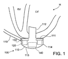
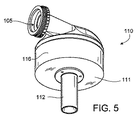
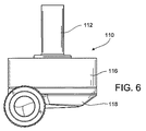
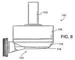
図1及び4−11を参照して説明すると、パック型ハウジング110を有する左心室補助血液ポンプ100が患者の体内に埋め込まれており、上記パック型ハウジング110の第1の面111は患者の心臓Hに向けられており、パック型ハウジング110の第2の面113は心臓Hとは反対側を向いている。パック型ハウジング110の第1の面111は心臓Hの左心室L.V内に延びている注入カニューラ112を含んでいる。ハウジング110の第2の面113は血液ポンプ100と接触するその患者の横隔膜などの他の組織を刺激するのを防ぐための面取りされた端部114を有している。図示されている形状のパック型ハウジング110をコンパクトな形で構成するために、ポンプ100の固定子120と電子部品130をハウジングの流入側に第1の面111に向けて配置させ、ポンプ100の回転子140を上記第2の面113に沿って配置させる。固定子120、電子部品130、及び回転子140をこのように配置することで、例えば、図2、4及び6−9に示してあるように、回転子140の輪郭に沿って端部114を面取りすることができる。
Referring to FIGS. 1 and 4-11, a left ventricular assist
図2を参照して説明すると、血液ポンプ100は血流導管103を形成しているハウジング110内に隔壁115を含んでいる。血流導管103は上記注入カニューラ112の注入開口部101から固定子120を通じてハウジング110によって形成される注出開口部105に延びている。上記回転子140は血流導管103内に配置されている。固定子120は回転子140の第1の部分140aの周りに円周状、例えば、永久磁石141の周りに配置されている。また、固定子120は回転子140に対して、使用時に、血液が回転子140に到達する前に固定子120を通じて血流導管103内部を流れるように配置される。永久磁石141は永久N磁極Nと永久S磁極Sを有しており、回転子140を受動的及び能動的に浮上させたり回転子140を回転させたりする。回転子140はインペラ・ブレード143を含む第2の部分140bも有している。インペラ・ブレード143は血流導管の螺旋状部分107内に配置されており、その結果インペラ・ブレード143がハウジング110の第2の面113に近接して配置されている。
Referring to FIG. 2,
パック型ハウジング110はさらに上記第1の面111と取り外し可能なキャップ118との間に延在する周辺側壁116を含んでいる。図に示されているように、この周辺側壁116は周辺側壁116の向かい合った部分間の巾Wを有する中空環状円筒部を有している。ハウジング110の第1の面111と第2の面113間の厚みTは巾Wより小さくなっている。厚みTは約0.5インチから約1.5インチの範囲で、巾Wは約1インチから約4インチの範囲である。例えば、巾Wを約2インチ、そして厚みTを約1インチとすることができる。
The pack-
周辺側壁116は内部区画117を含んでおり、この内部区画117は隔壁115と血流導管103を取り囲んでいて、固定子120と電子部品130はその内部区画117内部の隔壁115の周りに配置されている。取り外し可能なキャップ118は第2の面113と面取りされた端部114を含み、注入開口部105を形成している。取り外し可能なキャップ118は周辺側壁116とネジ式で係合して、キャップ118を周辺側壁116との係合状態で密封できるようになっている。キャップ118は内部面118aを含んでいて、この内部面118aは注入開口部105と液通している螺旋状部分107を形成している。
The
内部区画117内部で、電子部品130は第1の面111に近接して配置されており、固定子120は第1の面111から見て電子部品130の反対側に電子部品130に近接して配置されている。電子部品130は回路盤131とその回路盤131上に担持された固定子120に対する電源供給を制御することでポンプ100の作動を制御するための種々の構成部品133を含んでいる。ハウジング110は内部区画117内のスペースを効率的に使用するために上記第1の面111に全体としては平行に回路盤131を内部区画117に受け入れられるように構成されている。この回路盤は隔壁115に向けて半径方向内側に、そして、周辺側壁116に向けて半径方向外側にも延びている。例えば、上記内部区画117は通常は回路盤131を内部に収容するのに必要な以上のサイズではなく、さらに、熱放散、材料膨張、注封材料、及び/又は回路盤131を取り付ける際に用いられるその他の構成要素のためのスペース以上のサイズにはしない。従って、第一面111に隣接するハウジング110の外の部形状は全体としては回路盤131の形状と基本的には同じで、その外部寸法は回路盤131の寸法と比較してそれほど大きくない。
Inside the
さらに図2と図3を参照して説明すると、固定子120は一枚の地鉄121と隔壁115の周りに間隔を置いて配置された極片123a-123fを含んでいる。地鉄121は隔壁115の周りに延びており、磁束を誘導するための鋼鉄などの強磁性素材の全体としては平坦な円盤として形成されている。地鉄(back iron)121は制御用電子部品130の傍らに配置されていて、極片123a-123fのための基板を提供している。
2 and 3, the
極片123a-123fのそれぞれはL字型で、回転子140を回転させるための電磁場を発生するための駆動コイル125を有している。例えば、磁極片123aは地鉄121と接触して、その地鉄121から第2の面113の方向に延びる第1の脚124aを有している。磁極片123aは上記第1の脚124aから回転子140の永久磁石141の位置に近接する隔壁115の方向に延びる第2の脚124bも有している。極片123a-123fのそれぞれは、回転子140の半径方向位置を制御するための電磁場を発生する浮上コイル127も有している。
Each of the
駆動コイル125と浮上コイル127のそれぞれは磁極片123a-123fの周りに複数回巻きつけられた伝導体を含んでいる。具体的に言うと、駆動コイル125のそれぞれは例えば磁極片123dあと123eなどのような磁極片123のうちの2つの近接したのに周りに巻き付けられており、各浮上コイル127は1つの磁極片の周りに巻き付けられている。駆動コイル125と浮上コイル127は極片123の第1の脚の周りに巻き付けられており、使用時にコイル125及び127を通じて電流を送ることによって発生される磁束が磁極片123の第1及び第2の脚と地鉄121を通じて誘導される。固定子120の駆動コイル125と浮上コイル127は相互に向き合った対として配置されており、永久磁石141の永久磁極N及び永久磁極Sと相互作用する電磁場を発生させることによって回転子を駆動すると同時に回転子140を半径方向に浮上させるように制御される。固定子120が駆動コイル125及び浮上コイル127の両方を含んでいるので、受動的及び能動的磁力だけを用いて回転子140を浮上させるのにたった1つの固定子が必要なだけである。この構成の永久磁石141はただ1つの磁気モーメントを有するだけで一体的な永久磁気体141でつくられている。例えば、固定子120は米国特許第6,351,048号に記載されているように制御される。この特許は、本明細書で触れたので、その内容全体が本明細書に組み込まれる。制御用電子部品130と固定子120はケーブル119(図1参照)経由でリモート電源から電力を受け取る。
Each of
回転子140はその永久磁石141が注入開口部100のの周りの位置でインペラ・ブレードの上流に位置するように、ハウジング110内に配置される。永久磁石141は磁極片123の第2の脚124bに近接した血流導管103内に受け入れられ、永久磁石141と磁極片123の強磁性素材との相互作用を通じて受動的な軸方向センタリング力を提供する。回転子140の永久磁石141と隔壁115は、回転子140が隔壁115内で中心に位置されると、永久磁石141と隔壁115との間に空隙108を形成する。この空隙108は約0.2ミリメートルから約2ミリメートルの範囲であってよい。例えば、空隙108は約1ミリメートルである。永久磁石141の永久磁極Nと永久磁極Sは回転子140と固定子120間に永続的な磁気的吸引力を提供し、この力が固定子120内に概して中心化された回転子140を維持する傾向があり、回転子140が第1の面111あるいは第2の面113の方向に動くのを抑える傾向がある受動的な磁気吸引力として作用する。空隙108がより小さくなると、永久磁石141と固定子120間の磁気的な吸引力がより大きくなり、従って、空隙108の大きさは、永久磁石141が回転子140が隔壁115やキャップ118の内面118aに接触するのを制限するのに十分な程度の強さを有する受動的な軸方向センタリング力を提供できるように調整される。回転子140は第2の面113に向き合ったインペラ・ブレード143の端部を覆う覆い145も含んでおり、この覆い145は血流を螺旋状部分107に向かわせるのに役立つ。この覆い145とキャップ118の内面118aが、回転子140が固定子120によって浮上されると、覆い145と内面118aの間に空隙109を形成する。この空隙109は約0.2ミリメートルから約2ミリメートルの間の範囲である。例えば、空隙109は約1ミリメートルである。
The
血液が血流導管103を通じて流れると、その血液は永久磁石141を通じて形成されている中央の穴141aを通じて流れる。血液は回転子140と隔壁115との間の空隙108を通じて、さらに、覆い145とキャップ118の内面108aの間の空隙109を通じて流れる。空隙108及び109は血液が滞留すると起きる可能性がある凝固形成を制限するのに十分な血流をもたらすのに必要な大きさを持っている。また、空隙108及び109はポンプ100を通じて流れる際に血液が傷められないように、血液細胞に対する圧力を制限するのに十分な大きさも有している。血液細胞に対する圧力を制限するように空隙108及び109の大きさを調整した結果として、空隙108と109は有意な流体力学による懸濁効果を起こすのには大き過ぎる。つまり、血液は空隙108及び109内で軸受作用は発揮しないので、回転子が磁力によってのみ浮上される。
When blood flows through the
上に述べたように、回転子140は浮上コイル127の能動的制御によって半径方向に浮上し、回転子140は永久磁石141と固定子120の受動的な相互作用によって軸方向に浮上されるので、第2の面113の周りに回転子を浮上させる構成部品は必要としない。回転子を浮上させるためのすべての構成要素(つまり、浮上コイル127と磁極片123)を固定子120内に組み込んだので、キャップ118をインペラ・ブレード141と螺旋状部分107の形状に合わせることが可能になる。さらに、回転子浮上用の構成要素のすべてを固定子120内に組み込んだので、区画117からキャップ118に延びる電気コネクタの必要がなくなり、これによって、キャップを簡単に取り付けたり取り外したりできるようになり、ポンプを故障させる要因が一掃される。
As described above, the
使用時には、固定子120の駆動コイル125が磁極片123を通じて電磁場を発生させ、回転子140の磁極N及び磁極Sを選択的に吸引したり反撥したりして、回転子140を固定子120内で回転させる。回転子140が回転すると、インペラ・ブレード143が血液を螺旋状部分107内に押し込み、そして血液が注出開口部105から排出される。さらに、回転子が注入開口部101を通じてポンプ100内に血液を吸い込む。回転子140のインペラ・ブレード143の回転によって血液が血液ポンプ内に吸い込まれると、血液が注入開口部101を通じて流れ、さらに電子部品130と固定子120を通じて回転子140の方向に血液が流れる。血液は永久磁石141の穴141aを通じて流れ、さらにインペラ・ブレード143と覆い145と永久磁石141の間を通って、螺旋状部分107内に流れ込む。血液はまた回転子140の周りを流れ、空隙108と、覆い145とキャップ118の内面118aの間の空隙109を通じて流れる。血液は注出開口部105を通じて螺旋状部分107から出ていく。
In use, the driving
多数の実施例について上に説明した。しかし、ここに権利請求されている発明の精神と範囲から逸脱せずにいろいろな修正が可能であることは分かるであろう。例えば、スナップフィット係合方式や接着剤あるいは溶接などを含めて、異なった取り付け機構あるいは技術を用いて、キャップ118を周辺側壁116と係合させることができる。さらに、キャップ118が注出開口部105と面取りされた端部114を形成している場合について述べたが、注入開口部105及び/又は面取りされた端部114は周辺側壁116あるいは周辺側壁116とキャップ118の両方で形成することもできる。同様に、隔壁115をキャップ118の一部として形成することも出来る。
A number of embodiments have been described above. However, it will be appreciated that various modifications can be made without departing from the spirit and scope of the claimed invention. For example, the
さらに、回転子140は2つ以上の永久磁石を含むこともできる。磁極片123の数と構成も変えることができる。制御電子部品130の作動は固定子の磁極片及び回転子の永久磁石の数と位置に合わせて選択することが出来る。また、キャップ118を接着剤、溶接、スナップフィット、シュリンクフィットなどのその他の技術や構造を用いて周辺側壁と係合させることが可能である。同様に、第1の面111を周辺側壁116とは別個の素材でつくることも可能であり、第1の面111は注入カニューラ112を含めて、制御用電子部品130と固定子120を内部区画117内に取り付けた後、溶接などの方法で周辺側壁116に取り付けることも出来る。覆い145は省略することもできるし、オプションとして、その他の制御装置で代替させて望ましいポンプ効率を達成することも可能である。別のオプションとして、制御用電子部品130を患者の腹部に埋め込まれた別個のハウジングなどポンプ100外に配置することができるし、患者の体外に配置することも可能である。
Further, the
いくつかの実施例で、ハウジング110の寸法は上に述べたものと比較してより大きく、あるいはより小さくすることも可能である。同様に、ハウジング110の巾Wの厚みTに対する比率は上に述べた数値と違っていてもよい。例えば、巾Wは厚みTの約1.1倍から約5倍の範囲であってもよい。さらに、回転子140の永久磁石141は2つ以上のN及びS磁極対を含むことも出来る。周辺側壁116と隔壁115は環状断面を有する円筒として図示されているが、その一方あるいは両方を楕円形あるいはその他の不規則形状の断面を有するように形成することもできる。同様に、周辺側壁116をテーパー加工して、ハウジングの第1の面111から第2の面113へWの巾が一定ではないようにすることもできる。
In some embodiments, the dimensions of the
上に述べたように、いくつかの実施例で、血液ポンプ100を病気や手術及び/又はその他の措置からの回復期間中などの移行期に心臓を補助するために用いることができる。その他の実施例で、血液ポンプ100を用いて、患者の大動脈弁が手術のために封止された場合など、患者の心臓の機能を基本的には永続的なベースで部分的あるいは完全に代替させることも可能である。
As noted above, in some embodiments,
従って、その他の実施形態も以下の請求項に述べられている範囲内にある。
Accordingly, other embodiments are within the scope of the following claims.
Claims (23)
注入開口部と前記注入開口部からある角度に方向付けられた流出開口部とを画定しているハウジングと、
血液を運ぶための血流導管を画定している前記ハウジング内の隔壁であって、前記血流導管は、前記ハウジングの前記注入開口部と前記流出開口部との間に延在する隔壁と、
固定子と回転子とを含む回転モーターであって、前記固定子は、前記回転子と相互作用するように構成されたコイルを含み、前記血流導管が前記固定子を通って延在するように、前記固定子が前記ハウジング内で前記隔壁の周りに円周状に配置されている、回転モーターと
を含み、
前記固定子は、前記回転子の少なくとも一部の周りに円周状に配置されており、前記固定子は、前記血流導管が前記回転子に到達する前に前記固定子を通って延在するように、前記回転子に対して位置付けられており、前記回転子は、回転の回転子軸の周りを回転し、前記回転子は、前記回転子を駆動するための回転子磁石を含み、前記回転子磁石は、前記回転子の磁気浮遊のための永久磁極を含み、前記固定子は、回転の前記回転子軸に対して垂直な軸に沿って前記回転子磁石に重なる磁極片を含む、埋め込み可能な血液ポンプ。 An implantable blood pump, the implantable blood pump comprising:
A housing defining an infusion opening and an outflow opening oriented at an angle from the infusion opening;
A septum in the housing defining a blood flow conduit for carrying blood, the blood flow conduit extending between the injection opening and the outflow opening of the housing;
A rotary motor including a stator and a rotor, the stator including a coil configured to interact with the rotor such that the blood flow conduit extends through the stator. The stator is arranged circumferentially around the partition in the housing, and a rotation motor,
The stator is arranged circumferentially around at least a portion of the rotor, and the stator extends through the stator before the blood flow conduit reaches the rotor. as to the is positioned against the rotor, the rotor rotates about the rotor axis of rotation, said rotor comprises a rotor magnet for driving said rotor, the rotor magnet comprises a permanent magnetic pole for magnetic floating of the rotor, the stator comprises a pole piece overlaps the rotor magnet along an axis perpendicular to said rotor axis of rotation Implantable blood pump.
前記ハウジングは、前記第2の面から前記周辺側壁への丸みを帯びた移行部を含み、前記ハウジングは、前記第1の面から延在し、かつ、前記注入開口部と液通している注入カニューラをさらに含み、前記流出開口部は、前記第2の面および前記周辺側壁のうちの少なくとも1つにおいて画定されている、請求項1から5のいずれか1項に記載の埋め込み可能な血液ポンプ。 The housing includes a first surface defining the injection opening, a second surface facing the first surface, and a peripheral sidewall extending from the first surface to the second surface. And
The housing includes a rounded transition from the second surface to the peripheral sidewall, the housing extending from the first surface and in fluid communication with the injection opening The implantable blood pump of any one of claims 1 to 5, further comprising a cannula, wherein the outflow opening is defined in at least one of the second surface and the peripheral sidewall. .
前記回転子を前記血流導管内で半径方向中心に位置させるように構成された能動的電磁制御システムと
をさらに含み、
前記ハウジング内で前記隔壁の周りに配置された前記能動的電磁制御システムを制御するように構成された制御用電子部品をさらに含む、請求項1から7のいずれか1項に記載の埋め込み可能な血液ポンプ。 A passive magnetic control system configured to control the axial position of the rotor relative to the stator;
An active electromagnetic control system configured to center the rotor within the blood flow conduit in a radial center; and
8. The implantable device of any one of claims 1 to 7, further comprising control electronics configured to control the active electromagnetic control system disposed about the bulkhead within the housing. Blood pump.
パック型ハウジング内で内部隔壁の周りに円周状にモーター固定子と制御用電子部品とを組み入れることであって、前記内部隔壁は、前記ハウジングの注入開口部から流出開口部に延在する内部血流導管を画定しており、前記固定子は、前記内部血流導管が前記モーター固定子を通じて延在するようにハウジング内に組み入れられる、ことと、
磁気的に浮上される回転子に担持されるインペラ・ブレードが前記注入開口部から見て前記磁気的に浮上される回転子の下流にあるように、かつ、使用時に、前記インペラが前記固定子を通じて前記注入開口部から前記流出開口部に血液を汲み上げるように、前記内部血流導管内で磁気的に浮上され、かつ、前記固定子に取り囲まれている回転子を配置することであって、前記血液は、前記磁気的に浮上される回転子に到達する前に前記固定子を通って前記血流導管内を流れる、ことと
を含み、
前記磁気的に浮上される回転子は、回転の回転子軸の周りを回転し、前記磁気的に浮上される回転子は、前記磁気的に浮上される回転子を駆動するための回転子磁石を含み、前記固定子は、回転の前記回転子軸に対して垂直な軸に沿って前記回転子磁石に重なる磁極片を含む、方法。 A method of making a blood pump, the method comprising:
In a pack-type housing, a motor stator and control electronic components are incorporated circumferentially around an internal partition, the internal partition extending from an inlet opening of the housing to an outflow opening Defining a blood flow conduit, the stator being incorporated within a housing such that the internal blood flow conduit extends through the motor stator;
An impeller blade carried on a magnetically levitated rotor is downstream of the magnetically levitated rotor as seen from the injection opening and, in use, the impeller is in the stator Placing a rotor magnetically levitated in the internal blood flow conduit and surrounded by the stator so as to pump blood from the injection opening to the outflow opening through The blood flows through the stator and through the blood flow conduit before reaching the magnetically levitated rotor;
The magnetically levitated rotor rotates around a rotating rotor axis, and the magnetically levitated rotor is a rotor magnet for driving the magnetically levitated rotor wherein the said stator comprises a pole piece overlaps the rotor magnet along an axis perpendicular to said rotor axis of rotation, methods.
注入開口部と流出開口部とを画定しているハウジングと、
血流導管を画定している前記ハウジング内の隔壁であって、前記血流導管は、前記ハウジングの前記注入開口部と前記流出開口部との間に延在する、隔壁と、
固定子と回転子とを含む回転モーターであって、前記血流導管が前記固定子を通じて延在するように、前記固定子が前記ハウジング内で前記隔壁の周りに円周状に配置されており、前記固定子は、前記回転子の少なくとも一部の周りに円周状に配置されており、前記固定子は、使用時に、血液が前記回転子に到達する前に前記固定子を通じて前記血流導管内を流れるように前記回転子に対して位置付けられており、前記回転子は、回転の回転子軸の周りを回転し、前記回転子は、前記回転子を駆動するための回転子磁石を含み、前記回転子磁石は、前記回転子の磁気浮遊のための永久磁極を含み、前記固定子は、回転の前記回転子軸に対して垂直な軸に沿って前記回転子磁石に重なる磁極片を含む、回転モーターと、
前記固定子に対する前記回転子の軸方向の位置を制御するように構成された受動的磁気制御システムと、
前記回転子を前記血流導管内で半径方向中心に位置させるように構成された能動的電磁制御システムと
を含む、埋め込み可能な血液ポンプ。 An implantable blood pump, the implantable blood pump comprising:
A housing defining an inlet opening and an outlet opening;
A septum in the housing defining a blood flow conduit, the blood flow conduit extending between the inlet opening and the outlet opening of the housing;
A rotary motor including a stator and a rotor, wherein the stator is arranged circumferentially around the septum in the housing such that the blood flow conduit extends through the stator. The stator is arranged circumferentially around at least a portion of the rotor, and the stator is in use when the blood flow through the stator before blood reaches the rotor. has been positioned relative to the rotor to flow in a conduit, the rotor rotates about the rotor axis of rotation, the rotor, the rotor magnet for driving said rotor wherein said rotor magnet comprises a permanent magnetic pole for magnetic floating of the rotor, wherein the stator pole pieces overlapping the rotor magnet along an axis perpendicular to said rotor axis of rotation Including a rotary motor,
A passive magnetic control system configured to control the axial position of the rotor relative to the stator;
An implantable blood pump comprising: an active electromagnetic control system configured to position the rotor radially centrally within the blood flow conduit.
注入開口部と前記注入開口部からある角度に方向付けられた流出開口部とを画定しているハウジングと、
血液を運ぶための血流導管を画定している前記ハウジング内の隔壁であって、前記血流導管は、前記ハウジングの前記注入開口部と前記流出開口部との間に延在する、隔壁と、
固定子と回転子とを含む回転モーターであって、前記固定子は、前記回転子と相互作用するように構成されたコイルを含み、前記血流導管が前記固定子を通じて延在するように、前記固定子が前記ハウジング内で前記隔壁の周りに円周状に配置されており、前記固定子は、前記回転子の少なくとも一部の周りに円周状に配置されており、前記固定子は、前記血流導管が前記回転子に到達する前に前記固定子を通って延在するように前記回転子に対して位置付けられており、前記回転子は、前記回転子の磁気浮上のための永久磁極を有している、回転モーターと
を含み、
前記埋め込み可能な血液ポンプは、前記ハウジング内に配置された地鉄を含み、前記地鉄は、使用時に、血液が前記コイルに到達する前に前記地鉄を通じて前記血流導管内を流れるように、位置付けられている、埋め込み可能な血液ポンプ。 An implantable blood pump, the implantable blood pump comprising:
A housing defining an infusion opening and an outflow opening oriented at an angle from the infusion opening;
A septum in the housing defining a blood flow conduit for carrying blood, the blood flow conduit extending between the injection opening and the outflow opening of the housing; ,
A rotary motor including a stator and a rotor, the stator including a coil configured to interact with the rotor, such that the blood flow conduit extends through the stator; The stator is arranged circumferentially around the partition in the housing, the stator is arranged circumferentially around at least a part of the rotor, and the stator is The blood flow conduit is positioned relative to the rotor so as to extend through the stator before reaching the rotor, the rotor for magnetic levitation of the rotor A rotating motor having a permanent magnetic pole,
The implantable blood pump includes a ground iron disposed within the housing such that, in use, the ground iron flows through the blood flow conduit through the ground iron before reaching the coil. Positioned, implantable blood pump.
注入開口部と流出開口部とを画定しているハウジングと、
血流導管を画定している前記ハウジング内の隔壁であって、前記血流導管は、前記ハウジングの前記注入開口部と前記流出開口部との間に延在する、隔壁と、
固定子と回転子とを含む回転モーターであって、前記血流導管が前記固定子を通じて延在するように、前記固定子が前記ハウジング内で前記隔壁の周りに円周状に配置されており、前記固定子は、前記回転子の少なくとも一部の周りに円周状に配置されており、前記固定子は、使用時に、前記血液が前記回転子に到達する前に前記固定子を通じて前記血流導管内を流れるように前記回転子に対して位置付けられており、前記回転子は、回転の回転子軸の周りを回転し、前記回転子は、前記回転子を駆動するための回転子磁石を含み、前記回転子磁石は、前記回転子の磁気浮遊のための永久磁極を含み、前記固定子は、回転の前記回転子軸に対して垂直な軸に沿って前記回転子磁石に重なる磁極片を含む、回転モーターと、
前記固定子に対する前記回転子の軸方向の位置を制御するように構成された受動的磁気制御システムと、
前記回転子を前記血流導管内で半径方向中心に位置させるように構成された能動的電磁制御システムと
を含む、埋め込み可能な血液ポンプ。 An implantable blood pump, the implantable blood pump comprising:
A housing defining an inlet opening and an outlet opening;
A septum in the housing defining a blood flow conduit, the blood flow conduit extending between the inlet opening and the outlet opening of the housing;
A rotary motor including a stator and a rotor, wherein the stator is arranged circumferentially around the septum in the housing such that the blood flow conduit extends through the stator. The stator is arranged circumferentially around at least a portion of the rotor, and the stator, when in use, passes the blood through the stator before the blood reaches the rotor. has been positioned relative to the rotor so as to flow in a flow conduit, the rotor rotates about the rotor axis of rotation, the rotor, the rotor magnet for driving said rotor wherein the said rotor magnet comprises a permanent magnetic pole for magnetic floating of the rotor, the stator, overlapping the rotor magnet along an axis perpendicular to said rotor axis of rotation pole A rotary motor, including a piece,
A passive magnetic control system configured to control the axial position of the rotor relative to the stator;
An implantable blood pump comprising: an active electromagnetic control system configured to position the rotor radially centrally within the blood flow conduit.
注入開口部と流出開口部とを画定しているハウジングと、
血液を運ぶための血流導管を画定している前記ハウジング内の隔壁であって、前記血流導管は、前記ハウジングの前記注入開口部と前記流出開口部との間に延在する、隔壁と、
固定子と回転子とを含む回転モーターであって、前記血流導管が前記固定子を通じて延在するように、前記固定子が前記ハウジング内で前記隔壁の周りに円周状に配置されており、前記固定子は、前記回転子の少なくとも一部の周りに円周状に配置されており、前記固定子は、前記血流導管が前記回転子に到達する前に前記固定子を通って延在するように前記回転子に対して位置付けられており、前記回転子は、前記回転子の磁気浮上のための永久磁極を有している、回転モーターと
を含み、
前記固定子は、地鉄を含み、
前記固定子は、前記隔壁の周りに間隔を置いて配置された磁極片を含み、前記磁極片のそれぞれはL字型であり、
前記磁極片のそれぞれは、前記地鉄と接触して前記地鉄から延在する第1の脚を有しており、前記磁極片のそれぞれは、前記第1の脚から前記隔壁の方向に延在する第2の脚を有している、埋め込み可能な血液ポンプ。 An implantable blood pump, the implantable blood pump comprising:
And defining an injection opening and the outlet opening are housing,
A septum in the housing defining a blood flow conduit for carrying blood, the blood flow conduit extending between the injection opening and the outflow opening of the housing; ,
A rotary motor including a stator and a rotor, wherein the stator is arranged circumferentially around the septum in the housing such that the blood flow conduit extends through the stator. The stator is disposed circumferentially around at least a portion of the rotor, and the stator extends through the stator before the blood flow conduit reaches the rotor. A rotary motor positioned relative to the rotor, the rotor having a permanent magnetic pole for magnetic levitation of the rotor,
The stator includes a ground iron,
The stator includes pole pieces spaced around the partition, each of the pole pieces being L-shaped;
Each of the pole pieces has a first leg that contacts and extends from the ground iron, and each of the pole pieces extends from the first leg toward the partition wall. An implantable blood pump having a second leg present.
注入開口部と流出開口部を画定しているハウジングと、
血流導管を画定している前記ハウジング内の隔壁であって、前記血流導管は、前記ハウジングの前記注入開口部と前記流出開口部との間に延在する、隔壁と、
固定子と回転子とを含む回転モーターであって、前記血流導管が前記固定子を通じて延在するように、前記固定子が前記ハウジング内で前記隔壁の周りに円周状に配置されており、前記固定子は、前記回転子の少なくとも一部の周りに円周状に配置されており、前記固定子は、使用時に、前記血液が前記回転子に到達する前に前記固定子を通じて前記血流導管内を流れるように、前記回転子に対して位置付けられており、前記回転子は、回転の回転子軸の周りを回転し、前記回転子は、前記回転子を駆動するための回転子磁石を含み、前記回転子磁石は、前記回転子の磁気浮遊のための永久磁極を含み、前記固定子は、回転の前記回転子軸に対して垂直な軸に沿って前記回転子磁石に重なる磁極片を含む、回転モーターと、
前記回転子の磁気浮上のためのラジアル軸受として作用するように構成された能動的電磁制御システムと
を含む、埋め込み可能な血液ポンプ。 An implantable blood pump, the implantable blood pump comprising:
A housing defining an inlet opening and an outlet opening;
A septum in the housing defining a blood flow conduit, the blood flow conduit extending between the inlet opening and the outlet opening of the housing;
A rotary motor including a stator and a rotor, wherein the stator is arranged circumferentially around the septum in the housing such that the blood flow conduit extends through the stator. The stator is arranged circumferentially around at least a portion of the rotor, and the stator, when in use, passes the blood through the stator before the blood reaches the rotor. to flow through the flow conduit, wherein is positioned against the rotor, the rotor rotates about the rotor axis of rotation, the rotor, the rotor for driving the rotor includes a magnet, the rotor magnet comprises a permanent magnetic pole for magnetic floating of the rotor, the stator, overlapping the rotor magnet along an axis perpendicular to said rotor axis of rotation A rotary motor, including pole pieces;
An implantable blood pump comprising: an active electromagnetic control system configured to act as a radial bearing for magnetic levitation of the rotor.
Applications Claiming Priority (3)
| Application Number | Priority Date | Filing Date | Title |
|---|---|---|---|
| US37550410P | 2010-08-20 | 2010-08-20 | |
| US61/375,504 | 2010-08-20 | ||
| PCT/US2011/048259 WO2012024493A1 (en) | 2010-08-20 | 2011-08-18 | Implantable blood pump |
Publications (3)
| Publication Number | Publication Date |
|---|---|
| JP2013536021A JP2013536021A (en) | 2013-09-19 |
| JP2013536021A5 JP2013536021A5 (en) | 2014-08-28 |
| JP5977237B2 true JP5977237B2 (en) | 2016-08-24 |
Family
ID=44534700
Family Applications (1)
| Application Number | Title | Priority Date | Filing Date |
|---|---|---|---|
| JP2013524979A Expired - Fee Related JP5977237B2 (en) | 2010-08-20 | 2011-08-18 | Implantable blood pump |
Country Status (7)
| Country | Link |
|---|---|
| US (3) | US9091271B2 (en) |
| EP (2) | EP3248628B1 (en) |
| JP (1) | JP5977237B2 (en) |
| AU (1) | AU2011291984B2 (en) |
| CA (1) | CA2808658C (en) |
| TW (1) | TW201212960A (en) |
| WO (1) | WO2012024493A1 (en) |
Families Citing this family (89)
| Publication number | Priority date | Publication date | Assignee | Title |
|---|---|---|---|---|
| EP3248628B1 (en) | 2010-08-20 | 2019-01-02 | Tc1 Llc | Implantable blood pump |
| EP2995327A1 (en) | 2011-03-02 | 2016-03-16 | Thoratec Corporation | Ventricular cuff |
| DE102012200806B4 (en) * | 2012-01-20 | 2014-07-31 | Yasa Motors Poland Sp. z.o.o. | Wet runner pump with power electronics |
| US9981076B2 (en) | 2012-03-02 | 2018-05-29 | Tc1 Llc | Ventricular cuff |
| US9199019B2 (en) | 2012-08-31 | 2015-12-01 | Thoratec Corporation | Ventricular cuff |
| JP6034889B2 (en) | 2012-03-05 | 2016-11-30 | ソーラテック コーポレイション | Modular implantable medical pump |
| EP2890420B1 (en) * | 2012-08-31 | 2018-08-29 | Tc1 Llc | Instability detection algorithm for an implantable blood pump |
| US9492599B2 (en) | 2012-08-31 | 2016-11-15 | Thoratec Corporation | Hall sensor mounting in an implantable blood pump |
| WO2014036410A1 (en) * | 2012-08-31 | 2014-03-06 | Thoratec Corporation | Start-up algorithm for an implantable blood pump |
| US20140188148A1 (en) | 2012-12-27 | 2014-07-03 | Pieter W.C.J. le Blanc | Surgical tunneler |
| DE102013013700A1 (en) * | 2013-04-05 | 2014-10-09 | CircuLite GmbH | Implantable blood pump, blood pump system and method for data transmission in a blood pump system |
| US9744280B2 (en) | 2014-04-15 | 2017-08-29 | Tc1 Llc | Methods for LVAD operation during communication losses |
| EP3131598B1 (en) | 2014-04-15 | 2020-10-21 | Tc1 Llc | Systems for upgrading ventricle assist devices |
| US9786150B2 (en) | 2014-04-15 | 2017-10-10 | Tci Llc | Methods and systems for providing battery feedback to patient |
| US9849224B2 (en) | 2014-04-15 | 2017-12-26 | Tc1 Llc | Ventricular assist devices |
| US9526818B2 (en) | 2014-04-15 | 2016-12-27 | Thoratec Corporation | Protective cap for driveline cable connector |
| WO2015160991A1 (en) * | 2014-04-15 | 2015-10-22 | Thoratec Corporation | Methods and systems for controlling a blood pump |
| AT515555B1 (en) * | 2014-05-15 | 2015-10-15 | Tech Universität Wien | magnetic coupling |
| EP2962710A1 (en) | 2014-07-03 | 2016-01-06 | Berlin Heart GmbH | Method and heart support system for determining an outlet pressure |
| EP3189526B1 (en) | 2014-09-03 | 2019-07-31 | Tc1 Llc | Triple helix driveline cable and methods of assembly and use |
| WO2016187057A1 (en) | 2015-05-15 | 2016-11-24 | Thoratec Corporation | Improved axial flow blood pump |
| WO2017015210A1 (en) | 2015-07-20 | 2017-01-26 | Thoratec Corporation | Strain gauge for flow estimation |
| US9901666B2 (en) | 2015-07-20 | 2018-02-27 | Tc1 Llc | Flow estimation using hall-effect sensors for measuring impeller eccentricity |
| US10029038B2 (en) | 2015-07-21 | 2018-07-24 | Tc1 Llc | Cantilevered rotor pump and methods for axial flow blood pumping |
| WO2017040317A1 (en) | 2015-08-28 | 2017-03-09 | Thoratec Corporation | Blood pump controllers and methods of use for improved energy efficiency |
| WO2017087717A1 (en) | 2015-11-20 | 2017-05-26 | Tc1 Llc | Blood pump controllers having daisy-chained batteries |
| EP3677226B1 (en) | 2015-11-20 | 2021-12-22 | Tc1 Llc | Improved connectors and cables for use with ventricle assist systems |
| WO2017087380A1 (en) | 2015-11-20 | 2017-05-26 | Tc1 Llc | System architecture that allows patient replacement of vad controller/interface module without disconnection of old module |
| EP3377136B1 (en) | 2015-11-20 | 2020-05-06 | Tc1 Llc | Energy management of blood pump controllers |
| EP3222301B1 (en) * | 2016-03-23 | 2018-05-09 | Abiomed Europe GmbH | Blood pump |
| US9985374B2 (en) | 2016-05-06 | 2018-05-29 | Tc1 Llc | Compliant implantable connector and methods of use and manufacture |
| US10857273B2 (en) | 2016-07-21 | 2020-12-08 | Tc1 Llc | Rotary seal for cantilevered rotor pump and methods for axial flow blood pumping |
| US10660998B2 (en) | 2016-08-12 | 2020-05-26 | Tci Llc | Devices and methods for monitoring bearing and seal performance |
| US10894116B2 (en) | 2016-08-22 | 2021-01-19 | Tc1 Llc | Heart pump cuff |
| US10589013B2 (en) | 2016-08-26 | 2020-03-17 | Tci Llc | Prosthetic rib with integrated percutaneous connector for ventricular assist devices |
| EP3515527A4 (en) | 2016-09-26 | 2020-05-13 | Tc1 Llc | Heart pump driveline power modulation |
| WO2018075780A1 (en) | 2016-10-20 | 2018-04-26 | Tc1 Llc | Methods and systems for bone conduction audible alarms for mechanical circulatory support systems |
| US10053230B2 (en) * | 2016-12-26 | 2018-08-21 | Haoxiang Electric Energy (Kunshan) Co., Ltd. | Magnetic levitation obstacle avoidance device and magnetic levitation holder |
| WO2018132713A1 (en) | 2017-01-12 | 2018-07-19 | Tc1 Llc | Driveline bone anchors and methods of use |
| US10792407B2 (en) | 2017-01-12 | 2020-10-06 | Tc1 Llc | Percutaneous driveline anchor devices and methods of use |
| WO2018136592A2 (en) | 2017-01-18 | 2018-07-26 | Tc1 Llc | Systems and methods for transcutaneous power transfer using microneedles |
| WO2018156897A1 (en) | 2017-02-24 | 2018-08-30 | Tc1 Llc | Minimally invasive methods and devices for ventricular assist device implantation |
| EP3600477B1 (en) | 2017-03-29 | 2022-10-26 | Tc1 Llc | Communication architecture for heart treatment systems |
| WO2018183568A1 (en) | 2017-03-29 | 2018-10-04 | Tc1 Llc | Pressure sensing ventricular assist devices and methods of use |
| EP3600476B1 (en) | 2017-03-29 | 2021-09-01 | Tc1 Llc | Adjusting pump protocol based on irregular heart rhythm |
| US11020583B2 (en) | 2017-04-21 | 2021-06-01 | Tci Llc | Aortic connectors and methods of use |
| US10737007B2 (en) | 2017-04-28 | 2020-08-11 | Tc1 Llc | Patient adapter for driveline cable and methods |
| EP3621669B1 (en) * | 2017-05-11 | 2023-11-01 | Tc1 Llc | Thermal interconnect for implantable blood pump |
| EP3634528B1 (en) | 2017-06-07 | 2023-06-07 | Shifamed Holdings, LLC | Intravascular fluid movement devices, systems, and methods of use |
| CN111556763B (en) | 2017-11-13 | 2023-09-01 | 施菲姆德控股有限责任公司 | Intravascular fluid movement device and system |
| US11191947B2 (en) | 2018-01-02 | 2021-12-07 | Tc1 Llc | Fluid treatment system for a driveline cable and methods of assembly and use |
| US10973967B2 (en) * | 2018-01-10 | 2021-04-13 | Tc1 Llc | Bearingless implantable blood pump |
| US10701043B2 (en) | 2018-01-17 | 2020-06-30 | Tc1 Llc | Methods for physical authentication of medical devices during wireless pairing |
| DE102018201030A1 (en) | 2018-01-24 | 2019-07-25 | Kardion Gmbh | Magnetic coupling element with magnetic bearing function |
| WO2019152875A1 (en) | 2018-02-01 | 2019-08-08 | Shifamed Holdings, Llc | Intravascular blood pumps and methods of use and manufacture |
| US11529508B2 (en) | 2018-03-02 | 2022-12-20 | Tc1 Llc | Wearable accessory for ventricular assist system |
| EP3765113A1 (en) | 2018-03-15 | 2021-01-20 | Tc1 Llc | Methods and systems for preventing right heart failure |
| EP3768341A1 (en) | 2018-03-19 | 2021-01-27 | Tc1 Llc | Coordinated ventricular assist and cardiac rhythm management devices and methods |
| WO2019183126A1 (en) | 2018-03-20 | 2019-09-26 | Tc1 Llc | Mechanical gauge for estimating inductance changes in resonant power transfer systems with flexible coils for use with implanted medical devices |
| US11389641B2 (en) | 2018-03-21 | 2022-07-19 | Tc1 Llc | Modular flying lead cable and methods for use with heart pump controllers |
| EP3768340B1 (en) | 2018-03-21 | 2023-12-20 | Tc1 Llc | Improved driveline connectors and methods for use with heart pump controllers |
| US11076944B2 (en) | 2018-03-26 | 2021-08-03 | Tc1 Llc | Methods and systems for irrigating and capturing particulates during heart pump implantation |
| RU2683069C1 (en) * | 2018-03-29 | 2019-03-26 | Федеральное государственное бюджетное учреждение "Национальный медицинский исследовательский центр трансплантологии и искусственных органов имени академика В.И. Шумакова" Министерства здравоохранения Российской Федерации (ФГБУ "НМИЦ ТИО им. ак. В.И. Шумакова" Минздрава России) | Centrifugal pump for mechanical blood circulation support |
| WO2019212861A1 (en) | 2018-04-30 | 2019-11-07 | Tc1 Llc | Improved blood pump connectors |
| DE102018207611A1 (en) | 2018-05-16 | 2019-11-21 | Kardion Gmbh | Rotor bearing system |
| DE102018208541A1 (en) | 2018-05-30 | 2019-12-05 | Kardion Gmbh | Axial pump for a cardiac assist system and method of making an axial pump for a cardiac assist system |
| EP3801675B1 (en) | 2018-05-31 | 2024-01-03 | Tc1 Llc | Improved blood pump controllers |
| DE102018211327A1 (en) | 2018-07-10 | 2020-01-16 | Kardion Gmbh | Impeller for an implantable vascular support system |
| US10947986B2 (en) | 2018-07-11 | 2021-03-16 | Ch Biomedical (Usa) Inc. | Compact centrifugal pump with magnetically suspended impeller |
| US11241570B2 (en) | 2018-07-17 | 2022-02-08 | Tc1 Llc | Systems and methods for inertial sensing for VAD diagnostics and closed loop control |
| DE102018212153A1 (en) | 2018-07-20 | 2020-01-23 | Kardion Gmbh | Inlet line for a pump unit of a cardiac support system, cardiac support system and method for producing an inlet line for a pump unit of a cardiac support system |
| CN118557890A (en) | 2018-09-25 | 2024-08-30 | Tc1有限责任公司 | Adaptive speed control algorithm and controller for optimizing flow in ventricular assist devices |
| CN111298221B (en) * | 2018-12-12 | 2024-08-02 | 深圳核心医疗科技股份有限公司 | Ventricular assist device |
| JP2022540616A (en) | 2019-07-12 | 2022-09-16 | シファメド・ホールディングス・エルエルシー | Intravascular blood pump and methods of manufacture and use |
| WO2021016372A1 (en) | 2019-07-22 | 2021-01-28 | Shifamed Holdings, Llc | Intravascular blood pumps with struts and methods of use and manufacture |
| EP4034192A4 (en) | 2019-09-25 | 2023-11-29 | Shifamed Holdings, LLC | Intravascular blood pump systems and methods of use and control thereof |
| CN115298441A (en) | 2020-01-21 | 2022-11-04 | 波士顿科学国际有限公司 | Magnetic drive with flux enhancer for blood pump |
| DE102020102474A1 (en) | 2020-01-31 | 2021-08-05 | Kardion Gmbh | Pump for conveying a fluid and method for manufacturing a pump |
| US20210393941A1 (en) | 2020-06-17 | 2021-12-23 | Tc1 Llc | Extracorporeal blood pump assembly and methods of assembling same |
| CN112546425B (en) * | 2020-10-29 | 2021-07-23 | 苏州心擎医疗技术有限公司 | Magnetic suspension motor and magnetic suspension blood pump |
| US20220186732A1 (en) * | 2020-12-11 | 2022-06-16 | Sapphire Motors | Integrated pump assembly with one moving part with stacked stator |
| CN112472999A (en) * | 2020-12-22 | 2021-03-12 | 余顺周 | Blood pump |
| US20220331580A1 (en) | 2021-04-15 | 2022-10-20 | Tc1 Llc | Systems and methods for medical device connectors |
| CN114452527B (en) * | 2022-01-26 | 2023-04-25 | 苏州心擎医疗技术有限公司 | Device for assisting heart in the event of failure |
| US20240207600A1 (en) | 2022-02-16 | 2024-06-27 | Tc1 Llc | Real Time Heart Rate Monitoring for Close Loop Control and/or Artificial Pulse Synchronization of Implantable Ventricular Assist Devices |
| WO2023229899A1 (en) | 2022-05-26 | 2023-11-30 | Tc1 Llc | Tri-axis accelerometers for patient physiologic monitoring and closed loop control of implantable ventricular assist devices |
| WO2023235230A1 (en) | 2022-06-02 | 2023-12-07 | Tc1 Llc | Implanted connector booster sealing for implantable medical devices |
| WO2024050319A1 (en) | 2022-08-29 | 2024-03-07 | Tc1 Llc | Implantable electrical connector assembly |
| WO2024097236A1 (en) | 2022-11-01 | 2024-05-10 | Tc1 Llc | Assessment and management of adverse event risks in mechanical circulatory support patients |
Family Cites Families (167)
| Publication number | Priority date | Publication date | Assignee | Title |
|---|---|---|---|---|
| US888654A (en) | 1902-03-05 | 1908-05-26 | Charles H Tompkins | Means for transmitting power. |
| US845816A (en) | 1902-03-05 | 1907-03-05 | Charles H Tompkins | Centripetal-centrifugal pump and condenser. |
| US1026101A (en) | 1910-12-23 | 1912-05-14 | Elon A Marsh | Centrifugal pump. |
| US2128988A (en) | 1937-04-02 | 1938-09-06 | Christian John Russell | Game board |
| US2747512A (en) | 1951-05-24 | 1956-05-29 | Fouche Rene Paul | Motor pump |
| US2864552A (en) | 1954-08-18 | 1958-12-16 | Sir George Godfrey & Partners | Shaft or like bearings |
| CA645624A (en) | 1959-03-20 | 1962-07-24 | A. Buchhold Theodor | Electro-mechanical device |
| US3066849A (en) | 1960-08-18 | 1962-12-04 | Exemplar Inc | High vacuum pump systems |
| US3122101A (en) | 1960-09-22 | 1964-02-25 | North American Aviation Inc | Bearingless pump |
| US3225608A (en) | 1962-11-27 | 1965-12-28 | Gen Motors Corp | Diamagnetic suspension system |
| GB1165884A (en) | 1965-12-03 | 1969-10-01 | Newage Lyon Ltd | Improvements relating to Centrifugal Pumps |
| US3499274A (en) | 1967-08-25 | 1970-03-10 | Rector C Fergason | Cotton harvester |
| US3957389A (en) | 1967-10-26 | 1976-05-18 | Bio-Medicus, Inc. | Pumping apparatus and process characterized by gentle operation |
| DE1933031C3 (en) | 1969-06-30 | 1978-10-26 | Karl 5170 Juelich Boden | Magnetic storage |
| US3575536A (en) | 1969-02-07 | 1971-04-20 | Jet Spray Cooler Inc | Pump for beverage dispenser |
| US3608088A (en) | 1969-04-17 | 1971-09-28 | Univ Minnesota | Implantable blood pump |
| US3597022A (en) | 1969-07-22 | 1971-08-03 | Robert D Waldron | Diamagnetic levitation and/or stabilizing devices |
| US3647324A (en) | 1969-12-18 | 1972-03-07 | Edson Howard Rafferty | Electrically driven pumps capable of use as heart pumps |
| US3611815A (en) | 1969-12-24 | 1971-10-12 | Us Navy | Frictionless gyroscope |
| DE2163256A1 (en) | 1971-12-20 | 1973-07-26 | Maschf Augsburg Nuernberg Ag | FLOW MACHINE, IN PARTICULAR TURB PUMP, OR FLOW MEASUREMENT DEVICE FOR AN AGGRESSIVE, RADIOACTIVE OR CLEAN FLUID |
| GB1491710A (en) | 1974-08-15 | 1977-11-16 | Howarth A | Induction machines |
| DE2457783C2 (en) | 1974-12-06 | 1986-10-09 | Arthur Pfeiffer Vakuumtechnik Wetzlar Gmbh, 6334 Asslar | Magnetic storage |
| US4135253A (en) | 1976-11-30 | 1979-01-23 | Medtronic, Inc. | Centrifugal blood pump for cardiac assist |
| US4213207A (en) | 1978-04-07 | 1980-07-22 | Wilson Frederick M | Artificial heart and method of pumping blood |
| FR2451480A1 (en) | 1979-03-16 | 1980-10-10 | Belenger Jacques | MEDICAL CENTRIFUGAL PUMP |
| DE2919236C2 (en) | 1979-05-12 | 1982-08-12 | Kernforschungsanlage Jülich GmbH, 5170 Jülich | Magnetic floating bearing for one rotor |
| DE2938809A1 (en) | 1979-09-25 | 1981-04-02 | Siemens AG, 1000 Berlin und 8000 München | MAGNETIC FLOATING BEARING |
| JPS5696198A (en) | 1979-12-27 | 1981-08-04 | Matsushita Electric Ind Co Ltd | Pump |
| US4382199A (en) | 1980-11-06 | 1983-05-03 | Nu-Tech Industries, Inc. | Hydrodynamic bearing system for a brushless DC motor |
| JPS58500593A (en) | 1981-03-18 | 1983-04-21 | ブラム,ギユンタ−,ヴアルタ−,オツト− | Magnetically Suspended and Rotated Impeller Pump Device |
| US4688998A (en) | 1981-03-18 | 1987-08-25 | Olsen Don B | Magnetically suspended and rotated impellor pump apparatus and method |
| JPS57181996A (en) | 1981-04-30 | 1982-11-09 | Power Reactor & Nuclear Fuel Dev Corp | Mechanical pump for liquid metal |
| US4405286A (en) | 1982-01-21 | 1983-09-20 | The United States Of America As Represented By The Administrator Of The National Aeronautics And Space Administration | Actively suspended counter-rotating machine |
| US5078741A (en) | 1986-10-12 | 1992-01-07 | Life Extenders Corporation | Magnetically suspended and rotated rotor |
| US4944748A (en) | 1986-10-12 | 1990-07-31 | Bramm Gunter W | Magnetically suspended and rotated rotor |
| US4704121A (en) | 1983-09-28 | 1987-11-03 | Nimbus, Inc. | Anti-thrombogenic blood pump |
| DE3343186A1 (en) | 1983-11-29 | 1985-06-05 | Fraunhofer-Gesellschaft zur Förderung der angewandten Forschung e.V., 8000 München | MAGNETIC ROTOR BEARING |
| US4589822A (en) | 1984-07-09 | 1986-05-20 | Mici Limited Partnership Iv | Centrifugal blood pump with impeller |
| US4642036A (en) | 1984-09-17 | 1987-02-10 | Young Niels O | Magnet ball pump |
| FR2613791B1 (en) | 1987-04-09 | 1992-03-13 | Europ Propulsion | RADIAL MAGNETIC BEARING WITH EMERGENCY LANDING AND APPLICATION TO AN ACTIVE MAGNETIC SUSPENSION TURBOMACHINE |
| US4779614A (en) | 1987-04-09 | 1988-10-25 | Nimbus Medical, Inc. | Magnetically suspended rotor axial flow blood pump |
| US4844707A (en) | 1987-06-12 | 1989-07-04 | Kletschka Harold D | Rotary pump |
| US4876492A (en) | 1988-02-26 | 1989-10-24 | General Electric Company | Electronically commutated motor driven apparatus including an impeller in a housing driven by a stator on the housing |
| JPH01257792A (en) | 1988-04-06 | 1989-10-13 | Fujitsu Ltd | Pump device |
| JPH0216390A (en) | 1988-06-30 | 1990-01-19 | Shimadzu Corp | Turbo molecular drag pump |
| JPH0676798B2 (en) | 1988-08-22 | 1994-09-28 | 株式会社荏原製作所 | Centrifugal pump with magnetic bearing |
| US4878831A (en) | 1988-10-24 | 1989-11-07 | Forney International, Inc. | Infrared flame detector adaptable for different fuels |
| US4957504A (en) | 1988-12-02 | 1990-09-18 | Chardack William M | Implantable blood pump |
| JP2544825B2 (en) * | 1989-06-05 | 1996-10-16 | 株式会社荏原製作所 | Magnet pump |
| US5112202A (en) | 1990-01-31 | 1992-05-12 | Ntn Corporation | Turbo pump with magnetically supported impeller |
| JP3006865B2 (en) * | 1990-10-11 | 2000-02-07 | エヌティエヌ株式会社 | Turbo pump |
| FR2659396B1 (en) | 1990-03-07 | 1992-05-15 | Cit Alcatel | VACUUM PUMP FOR CLEAN MOLECULAR VACUUM. |
| US5112200A (en) | 1990-05-29 | 1992-05-12 | Nu-Tech Industries, Inc. | Hydrodynamically suspended rotor axial flow blood pump |
| US5470208A (en) | 1990-10-05 | 1995-11-28 | Kletschka; Harold D. | Fluid pump with magnetically levitated impeller |
| US5195877A (en) | 1990-10-05 | 1993-03-23 | Kletschka Harold D | Fluid pump with magnetically levitated impeller |
| US5055005A (en) | 1990-10-05 | 1991-10-08 | Kletschka Harold D | Fluid pump with levitated impeller |
| US5177387A (en) | 1990-12-04 | 1993-01-05 | University Of Houston-University Park | High temperature superconducting magnetic bearings |
| US5159219A (en) | 1991-05-16 | 1992-10-27 | University Of Houston-University Park | Opposed-magnet bearing with interposed superconductor |
| US5220232A (en) | 1991-09-03 | 1993-06-15 | Allied Signal Aerospace | Stacked magnet superconducting bearing |
| JP2999607B2 (en) | 1991-09-30 | 2000-01-17 | 日本精工株式会社 | Superconducting bearing device and its operation method |
| WO1994003731A1 (en) | 1992-07-30 | 1994-02-17 | Spin Corporation | Centrifugal blood pump |
| US5527159A (en) | 1993-11-10 | 1996-06-18 | The United States Of America As Represented By The Administrator Of The National Aeronautics And Space Administration | Rotary blood pump |
| US5708346A (en) | 1994-01-10 | 1998-01-13 | Sulzer Electronics Ag | Method and control apparatus for controlling an AC-machine |
| US6808482B1 (en) | 1994-04-15 | 2004-10-26 | Allegheny-Singer Research Institute | Blood pump device and method of producing |
| US5808437A (en) | 1994-12-02 | 1998-09-15 | Sulzer Electronics Ag | Method for compensation of periodic shaking forces in an electrical rotating field machine |
| US6100618A (en) | 1995-04-03 | 2000-08-08 | Sulzer Electronics Ag | Rotary machine with an electromagnetic rotary drive |
| US5725357A (en) | 1995-04-03 | 1998-03-10 | Ntn Corporation | Magnetically suspended type pump |
| WO1997007340A1 (en) | 1995-08-18 | 1997-02-27 | Sulzer Electronics Ag | Magnetic bearing and process for operating it |
| US5947703A (en) | 1996-01-31 | 1999-09-07 | Ntn Corporation | Centrifugal blood pump assembly |
| JP3553255B2 (en) | 1996-01-31 | 2004-08-11 | Ntn株式会社 | Magnetic levitation pump with viscosity measurement function |
| US5840070A (en) | 1996-02-20 | 1998-11-24 | Kriton Medical, Inc. | Sealless rotary blood pump |
| KR20000010736A (en) * | 1996-05-03 | 2000-02-25 | 얀센 크리스 | Electromagnetically suspended and rotated centrifugal pumping device |
| US6302661B1 (en) | 1996-05-03 | 2001-10-16 | Pratap S. Khanwilkar | Electromagnetically suspended and rotated centrifugal pumping apparatus and method |
| US6394769B1 (en) | 1996-05-03 | 2002-05-28 | Medquest Products, Inc. | Pump having a magnetically suspended rotor with one active control axis |
| US6244835B1 (en) * | 1996-06-26 | 2001-06-12 | James F. Antaki | Blood pump having a magnetically suspended rotor |
| DE59706479D1 (en) | 1996-07-25 | 2002-04-04 | Lust Antriebstechnik Gmbh | Arrangement and method for operating a magnetically levitated, electromotive drive device in the event of a network fault |
| EP0860046B1 (en) | 1996-09-10 | 2003-02-26 | Levitronix LLC | Rotary pump |
| AUPO902797A0 (en) | 1997-09-05 | 1997-10-02 | Cortronix Pty Ltd | A rotary blood pump with hydrodynamically suspended impeller |
| DE59712591D1 (en) | 1997-08-25 | 2006-05-04 | Levitronix Llc | Magnetic bearing rotation arrangement |
| ATE345825T1 (en) | 1997-10-02 | 2006-12-15 | Micromed Technology Inc | CONTROL MODULE FOR IMPLANTABLE PUMP SYSTEM |
| US6293901B1 (en) | 1997-11-26 | 2001-09-25 | Vascor, Inc. | Magnetically suspended fluid pump and control system |
| US5928131A (en) | 1997-11-26 | 1999-07-27 | Vascor, Inc. | Magnetically suspended fluid pump and control system |
| CA2330048C (en) * | 1998-04-22 | 2004-04-20 | University Of Utah | Implantable centrifugal blood pump with hybrid magnetic bearings |
| DE59814131D1 (en) | 1998-06-22 | 2008-01-10 | Levitronix Llc | Method for determining the viscosity of a liquid |
| DE59915262D1 (en) | 1998-07-10 | 2011-06-01 | Levitronix Llc | Method for determining the pressure loss and the flow through a pump |
| DE59915016D1 (en) | 1998-08-24 | 2009-06-18 | Levitronix Llc | Method for determining the radial position of a permanent magnet rotor and electromagnetic rotary drive |
| DE59914570D1 (en) | 1998-08-24 | 2008-01-17 | Levitronix Llc | Sensor arrangement in an electromagnetic rotary drive |
| EP0989656B1 (en) | 1998-09-24 | 2009-03-11 | Levitronix LLC | Permanent magnet excited electric rotary drive |
| DE29821565U1 (en) | 1998-12-02 | 2000-06-15 | Impella Cardiotechnik AG, 52074 Aachen | Bearingless blood pump |
| US6264635B1 (en) | 1998-12-03 | 2001-07-24 | Kriton Medical, Inc. | Active magnetic bearing system for blood pump |
| AUPP995999A0 (en) | 1999-04-23 | 1999-05-20 | University Of Technology, Sydney | Non-contact estimation and control system |
| US6234772B1 (en) | 1999-04-28 | 2001-05-22 | Kriton Medical, Inc. | Rotary blood pump |
| US6146325A (en) | 1999-06-03 | 2000-11-14 | Arrow International, Inc. | Ventricular assist device |
| EP1063753B1 (en) | 1999-06-22 | 2009-07-22 | Levitronix LLC | Electric rotary drive comprising a magnetically suspended rotor |
| US7138776B1 (en) | 1999-07-08 | 2006-11-21 | Heartware, Inc. | Method and apparatus for controlling brushless DC motors in implantable medical devices |
| EP1113177B1 (en) | 1999-12-27 | 2003-12-03 | Ntn Corporation | Magnetically levitated pump |
| WO2001072352A2 (en) | 2000-03-27 | 2001-10-04 | The Cleveland Clinic Foundation | Chronic performance control system for rotodynamic blood pumps |
| US6559567B2 (en) | 2000-05-12 | 2003-05-06 | Levitronix Llc | Electromagnetic rotary drive |
| JP2001336528A (en) | 2000-05-25 | 2001-12-07 | Ntn Corp | Magnetic levitation device |
| US6589030B2 (en) | 2000-06-20 | 2003-07-08 | Ntn Corporation | Magnetically levitated pump apparatus |
| US6808508B1 (en) | 2000-09-13 | 2004-10-26 | Cardiacassist, Inc. | Method and system for closed chest blood flow support |
| US6626644B2 (en) | 2000-10-30 | 2003-09-30 | Ntn Corporation | Magnetically levitated pump and controlling circuit |
| US6707200B2 (en) | 2000-11-14 | 2004-03-16 | Airex Corporation | Integrated magnetic bearing |
| US6761532B2 (en) * | 2001-03-14 | 2004-07-13 | Vascor, Inc. | Touch down of blood pump impellers |
| DE10123139B4 (en) | 2001-04-30 | 2005-08-11 | Berlin Heart Ag | Method for controlling a support pump for pulsatile pressure fluid delivery systems |
| DE10123138B4 (en) | 2001-04-30 | 2007-09-27 | Berlin Heart Ag | Method for position control of a permanently magnetically mounted rotating component |
| JP3834610B2 (en) | 2001-07-12 | 2006-10-18 | 独立行政法人産業技術総合研究所 | Artificial heart pump with hydrodynamic bearing |
| US6640617B2 (en) | 2001-08-16 | 2003-11-04 | Levitronix Llc | Apparatus and a method for determining the viscosity of a fluid |
| JP2003093500A (en) * | 2001-09-27 | 2003-04-02 | Nikkiso Co Ltd | Blood pump |
| US6641378B2 (en) | 2001-11-13 | 2003-11-04 | William D. Davis | Pump with electrodynamically supported impeller |
| US7396327B2 (en) | 2002-01-07 | 2008-07-08 | Micromed Technology, Inc. | Blood pump system and method of operation |
| US6901212B2 (en) | 2002-06-13 | 2005-05-31 | Halliburton Energy Services, Inc. | Digital adaptive sensorless commutational drive controller for a brushless DC motor |
| US7338521B2 (en) | 2002-06-13 | 2008-03-04 | World Heart, Inc. | Low profile inlet for an implantable blood pump |
| US6949066B2 (en) | 2002-08-21 | 2005-09-27 | World Heart Corporation | Rotary blood pump diagnostics and cardiac output controller |
| US7284956B2 (en) | 2002-09-10 | 2007-10-23 | Miwatec Co., Ltd. | Methods and apparatus for controlling a continuous flow rotary blood pump |
| US6817836B2 (en) | 2002-09-10 | 2004-11-16 | Miwatec Incorporated | Methods and apparatus for controlling a continuous flow rotary blood pump |
| US7511443B2 (en) | 2002-09-26 | 2009-03-31 | Barrett Technology, Inc. | Ultra-compact, high-performance motor controller and method of using same |
| JP4041376B2 (en) | 2002-09-30 | 2008-01-30 | テルモ株式会社 | Blood pump device |
| DE10330434A1 (en) | 2003-07-04 | 2005-02-03 | Jostra Ag | Centrifugal pump |
| US7229258B2 (en) | 2003-09-25 | 2007-06-12 | Medforte Research Foundation | Streamlined unobstructed one-pass axial-flow pump |
| US7070398B2 (en) | 2003-09-25 | 2006-07-04 | Medforte Research Foundation | Axial-flow blood pump with magnetically suspended, radially and axially stabilized impeller |
| ATE406685T1 (en) | 2003-10-03 | 2008-09-15 | Foster Miller Inc | ROTARY PUMP WITH LCR ELECTROMAGNETIC BEARING |
| EP1670524A4 (en) * | 2003-10-09 | 2012-12-26 | Thoratec Corp | Impeller |
| JP4521547B2 (en) | 2004-04-15 | 2010-08-11 | 株式会社サンメディカル技術研究所 | Blood pump flow estimation device |
| US7591777B2 (en) | 2004-05-25 | 2009-09-22 | Heartware Inc. | Sensorless flow estimation for implanted ventricle assist device |
| US8303482B2 (en) | 2004-09-07 | 2012-11-06 | Micromed | Method and system for physiologic control of a blood pump |
| US8419609B2 (en) * | 2005-10-05 | 2013-04-16 | Heartware Inc. | Impeller for a rotary ventricular assist device |
| USD534548S1 (en) | 2005-05-26 | 2007-01-02 | Matsushita Electric Industrial Co., Ltd. | Pump |
| CA2611313A1 (en) | 2005-06-06 | 2006-12-14 | The Cleveland Clinic Foundation | Blood pump |
| JP4517076B2 (en) * | 2005-06-23 | 2010-08-04 | 独立行政法人産業技術総合研究所 | Artificial heart pump with hydrodynamic bearing |
| CN103432637B (en) | 2006-01-13 | 2016-12-28 | 哈特威尔公司 | Rotary blood pump |
| US8672611B2 (en) | 2006-01-13 | 2014-03-18 | Heartware, Inc. | Stabilizing drive for contactless rotary blood pump impeller |
| US8157720B2 (en) | 2006-01-27 | 2012-04-17 | Circulite, Inc. | Heart assist system |
| US7850594B2 (en) | 2006-05-09 | 2010-12-14 | Thoratec Corporation | Pulsatile control system for a rotary blood pump |
| EP2136861B1 (en) | 2007-04-05 | 2017-12-20 | ReliantHeart Inc. | Blood pump system |
| EP2145108B1 (en) | 2007-04-30 | 2019-10-02 | HeartWare, Inc. | Centrifugal rotary blood pump |
| JP5752413B2 (en) | 2007-06-06 | 2015-07-22 | ワールドハート コーポレイション | Wearable VAD controller with spare battery |
| CA2689651A1 (en) | 2007-06-06 | 2008-12-18 | Worldheart Corporation | Implantable vad with replaceable percutaneous cable |
| EP2037236A3 (en) | 2007-09-11 | 2011-01-19 | Levitronix LLC | Calibration method of a flow measurement in a flow system and a flow system for carrying out the method |
| JP2011515174A (en) | 2008-03-26 | 2011-05-19 | カーディオ アシスト リミテッド | Cardiac assist device |
| US8729758B2 (en) | 2008-04-30 | 2014-05-20 | Levitronix Gmbh | Rotational machine, method for the determination of a tilting of a rotor of a rotational machine, as well as a processing plant |
| EP2315609B1 (en) * | 2008-08-08 | 2015-12-02 | Calon Cardio Technology Ltd | Heart assist apparatus |
| JP5103331B2 (en) | 2008-09-01 | 2012-12-19 | 川崎重工業株式会社 | Marine thruster |
| AU2009296514B2 (en) * | 2008-09-26 | 2014-04-10 | Carnegie Mellon University | Magnetically-levitated blood pump with optimization method enabling miniaturization |
| JP4996578B2 (en) | 2008-10-28 | 2012-08-08 | 株式会社サンメディカル技術研究所 | Medical device or instrument comprising a porous structure |
| US8517699B2 (en) | 2008-12-16 | 2013-08-27 | Cleveland Clinic Foundation | Centrifugal pump with offset volute |
| WO2010118475A1 (en) * | 2009-04-16 | 2010-10-21 | Bivacor Pty Ltd | Heart pump controller |
| US9583991B2 (en) | 2009-06-24 | 2017-02-28 | Synchrony, Inc. | Systems, devices, and/or methods for managing magnetic bearings |
| EP2273124B1 (en) | 2009-07-06 | 2015-02-25 | Levitronix GmbH | Centrifugal pump and method for compensating for the axial impulse in a centrifugal pump |
| EP2319552B1 (en) | 2009-11-06 | 2014-01-08 | Berlin Heart GmbH | Blood pump |
| EP2357374B1 (en) | 2010-01-29 | 2016-02-17 | Levitronix GmbH | Magnetic bearing device |
| US8870739B2 (en) | 2010-08-06 | 2014-10-28 | Heartware, Inc. | Conduit device for use with a ventricular assist device |
| EP3248628B1 (en) | 2010-08-20 | 2019-01-02 | Tc1 Llc | Implantable blood pump |
| WO2012028181A1 (en) | 2010-09-01 | 2012-03-08 | Levitronix Gmbh | Rotary pump |
| WO2012054490A1 (en) | 2010-10-18 | 2012-04-26 | World Heart Corporation | Blood pump with splitter impeller blades and splitter stator vanes and methods of manufacturing |
| WO2012071065A1 (en) | 2010-11-23 | 2012-05-31 | Minnetronix Inc. | Portable controller with integral power source for mechanical circulation support systems |
| KR20140015291A (en) | 2010-12-09 | 2014-02-06 | 하트웨어, 인코포레이티드 | Controller and power source for implantable blood pump |
| WO2012100210A1 (en) | 2011-01-21 | 2012-07-26 | Heartware, Inc. | Flow estimation in a blood pump |
| US9492601B2 (en) | 2011-01-21 | 2016-11-15 | Heartware, Inc. | Suction detection on an axial blood pump using BEMF data |
| US8535212B2 (en) | 2011-03-30 | 2013-09-17 | Jarvik Robert | Centrifugal blood pumps with reverse flow washout |
| DE112012002922T5 (en) | 2011-07-11 | 2014-03-27 | Vascor, Inc. | Transcutaneous power transmission and communication for implanted cardiac support and other devices |
| GB2517609B (en) | 2012-06-08 | 2017-05-31 | Cameron Int Corp | Artificial heart system |
| US9364596B2 (en) | 2013-01-04 | 2016-06-14 | HeartWave, Inc. | Controller and power source for implantable blood pump |
| US8882477B2 (en) | 2013-03-14 | 2014-11-11 | Circulite, Inc. | Magnetically levitated and driven blood pump and method for using the same |
| DE102013013700A1 (en) | 2013-04-05 | 2014-10-09 | CircuLite GmbH | Implantable blood pump, blood pump system and method for data transmission in a blood pump system |
| US9427508B2 (en) | 2013-06-04 | 2016-08-30 | Heartware, Inc. | Axial flow pump pressure algorithm |
| JP6246928B2 (en) | 2013-08-14 | 2017-12-13 | ハートウェア, インコーポレイテッドHeartware, Inc. | Impeller for axial pump |
-
2011
- 2011-08-18 EP EP17178651.0A patent/EP3248628B1/en active Active
- 2011-08-18 AU AU2011291984A patent/AU2011291984B2/en not_active Ceased
- 2011-08-18 WO PCT/US2011/048259 patent/WO2012024493A1/en active Application Filing
- 2011-08-18 EP EP11750037.1A patent/EP2605809B1/en active Active
- 2011-08-18 CA CA2808658A patent/CA2808658C/en not_active Expired - Fee Related
- 2011-08-18 JP JP2013524979A patent/JP5977237B2/en not_active Expired - Fee Related
- 2011-08-18 US US13/212,813 patent/US9091271B2/en active Active
- 2011-08-19 TW TW100129901A patent/TW201212960A/en unknown
-
2015
- 2015-06-10 US US14/735,990 patent/US9675741B2/en active Active
-
2017
- 2017-05-12 US US15/594,373 patent/US10500321B2/en active Active
Also Published As
| Publication number | Publication date |
|---|---|
| US10500321B2 (en) | 2019-12-10 |
| EP2605809A1 (en) | 2013-06-26 |
| US20150273125A1 (en) | 2015-10-01 |
| AU2011291984A1 (en) | 2013-03-14 |
| US20120046514A1 (en) | 2012-02-23 |
| EP3248628B1 (en) | 2019-01-02 |
| TW201212960A (en) | 2012-04-01 |
| US9675741B2 (en) | 2017-06-13 |
| WO2012024493A1 (en) | 2012-02-23 |
| JP2013536021A (en) | 2013-09-19 |
| EP2605809B1 (en) | 2017-10-11 |
| AU2011291984B2 (en) | 2014-08-28 |
| US20170246365A1 (en) | 2017-08-31 |
| CA2808658C (en) | 2017-02-28 |
| EP3248628A1 (en) | 2017-11-29 |
| CA2808658A1 (en) | 2012-02-23 |
| US9091271B2 (en) | 2015-07-28 |
Similar Documents
| Publication | Publication Date | Title |
|---|---|---|
| JP5977237B2 (en) | Implantable blood pump | |
| US10413650B2 (en) | Hall sensor mounting in an implantable blood pump | |
| JP6067606B2 (en) | Rotary blood pump | |
| US11654273B2 (en) | Blood pump supported by passive magnetic forces | |
| EP2145108B1 (en) | Centrifugal rotary blood pump | |
| JP2013536021A5 (en) | ||
| WO2016187057A1 (en) | Improved axial flow blood pump | |
| EP3313471A1 (en) | Ventricular assist devices having a hollow rotor and methods of use | |
| US20140309481A1 (en) | Rotary pump with levitated impeller having thrust bearing for improved startup | |
| EP3621669B1 (en) | Thermal interconnect for implantable blood pump | |
| KR100805268B1 (en) | Rotary blood pump |
Legal Events
| Date | Code | Title | Description |
|---|---|---|---|
| RD03 | Notification of appointment of power of attorney |
Free format text: JAPANESE INTERMEDIATE CODE: A7423 Effective date: 20140605 |
|
| RD04 | Notification of resignation of power of attorney |
Free format text: JAPANESE INTERMEDIATE CODE: A7424 Effective date: 20140611 |
|
| A521 | Request for written amendment filed |
Free format text: JAPANESE INTERMEDIATE CODE: A523 Effective date: 20140711 |
|
| A621 | Written request for application examination |
Free format text: JAPANESE INTERMEDIATE CODE: A621 Effective date: 20140711 |
|
| A977 | Report on retrieval |
Free format text: JAPANESE INTERMEDIATE CODE: A971007 Effective date: 20150522 |
|
| A131 | Notification of reasons for refusal |
Free format text: JAPANESE INTERMEDIATE CODE: A131 Effective date: 20150615 |
|
| A521 | Request for written amendment filed |
Free format text: JAPANESE INTERMEDIATE CODE: A523 Effective date: 20150909 |
|
| A131 | Notification of reasons for refusal |
Free format text: JAPANESE INTERMEDIATE CODE: A131 Effective date: 20160112 |
|
| A521 | Request for written amendment filed |
Free format text: JAPANESE INTERMEDIATE CODE: A523 Effective date: 20160329 |
|
| TRDD | Decision of grant or rejection written | ||
| A01 | Written decision to grant a patent or to grant a registration (utility model) |
Free format text: JAPANESE INTERMEDIATE CODE: A01 Effective date: 20160707 |
|
| A61 | First payment of annual fees (during grant procedure) |
Free format text: JAPANESE INTERMEDIATE CODE: A61 Effective date: 20160721 |
|
| R150 | Certificate of patent or registration of utility model |
Ref document number: 5977237 Country of ref document: JP Free format text: JAPANESE INTERMEDIATE CODE: R150 |
|
| S111 | Request for change of ownership or part of ownership |
Free format text: JAPANESE INTERMEDIATE CODE: R313113 |
|
| S533 | Written request for registration of change of name |
Free format text: JAPANESE INTERMEDIATE CODE: R313533 |
|
| R350 | Written notification of registration of transfer |
Free format text: JAPANESE INTERMEDIATE CODE: R350 |
|
| R250 | Receipt of annual fees |
Free format text: JAPANESE INTERMEDIATE CODE: R250 |
|
| LAPS | Cancellation because of no payment of annual fees |