EP3640467B1 - Turbotriebwerk mit thermoakustischem system - Google Patents
Turbotriebwerk mit thermoakustischem system Download PDFInfo
- Publication number
- EP3640467B1 EP3640467B1 EP19186990.8A EP19186990A EP3640467B1 EP 3640467 B1 EP3640467 B1 EP 3640467B1 EP 19186990 A EP19186990 A EP 19186990A EP 3640467 B1 EP3640467 B1 EP 3640467B1
- Authority
- EP
- European Patent Office
- Prior art keywords
- turbomachine
- heat pipe
- exchanger
- acoustic
- panel
- Prior art date
- Legal status (The legal status is an assumption and is not a legal conclusion. Google has not performed a legal analysis and makes no representation as to the accuracy of the status listed.)
- Active
Links
Images


Classifications
-
- F—MECHANICAL ENGINEERING; LIGHTING; HEATING; WEAPONS; BLASTING
- F02—COMBUSTION ENGINES; HOT-GAS OR COMBUSTION-PRODUCT ENGINE PLANTS
- F02C—GAS-TURBINE PLANTS; AIR INTAKES FOR JET-PROPULSION PLANTS; CONTROLLING FUEL SUPPLY IN AIR-BREATHING JET-PROPULSION PLANTS
- F02C7/00—Features, components parts, details or accessories, not provided for in, or of interest apart form groups F02C1/00 - F02C6/00; Air intakes for jet-propulsion plants
- F02C7/12—Cooling of plants
- F02C7/14—Cooling of plants of fluids in the plant, e.g. lubricant or fuel
-
- F—MECHANICAL ENGINEERING; LIGHTING; HEATING; WEAPONS; BLASTING
- F02—COMBUSTION ENGINES; HOT-GAS OR COMBUSTION-PRODUCT ENGINE PLANTS
- F02C—GAS-TURBINE PLANTS; AIR INTAKES FOR JET-PROPULSION PLANTS; CONTROLLING FUEL SUPPLY IN AIR-BREATHING JET-PROPULSION PLANTS
- F02C7/00—Features, components parts, details or accessories, not provided for in, or of interest apart form groups F02C1/00 - F02C6/00; Air intakes for jet-propulsion plants
- F02C7/24—Heat or noise insulation
-
- F—MECHANICAL ENGINEERING; LIGHTING; HEATING; WEAPONS; BLASTING
- F02—COMBUSTION ENGINES; HOT-GAS OR COMBUSTION-PRODUCT ENGINE PLANTS
- F02K—JET-PROPULSION PLANTS
- F02K1/00—Plants characterised by the form or arrangement of the jet pipe or nozzle; Jet pipes or nozzles peculiar thereto
- F02K1/78—Other construction of jet pipes
- F02K1/82—Jet pipe walls, e.g. liners
- F02K1/827—Sound absorbing structures or liners
-
- F—MECHANICAL ENGINEERING; LIGHTING; HEATING; WEAPONS; BLASTING
- F02—COMBUSTION ENGINES; HOT-GAS OR COMBUSTION-PRODUCT ENGINE PLANTS
- F02K—JET-PROPULSION PLANTS
- F02K3/00—Plants including a gas turbine driving a compressor or a ducted fan
- F02K3/02—Plants including a gas turbine driving a compressor or a ducted fan in which part of the working fluid by-passes the turbine and combustion chamber
- F02K3/04—Plants including a gas turbine driving a compressor or a ducted fan in which part of the working fluid by-passes the turbine and combustion chamber the plant including ducted fans, i.e. fans with high volume, low pressure outputs, for augmenting the jet thrust, e.g. of double-flow type
- F02K3/06—Plants including a gas turbine driving a compressor or a ducted fan in which part of the working fluid by-passes the turbine and combustion chamber the plant including ducted fans, i.e. fans with high volume, low pressure outputs, for augmenting the jet thrust, e.g. of double-flow type with front fan
-
- G—PHYSICS
- G10—MUSICAL INSTRUMENTS; ACOUSTICS
- G10K—SOUND-PRODUCING DEVICES; METHODS OR DEVICES FOR PROTECTING AGAINST, OR FOR DAMPING, NOISE OR OTHER ACOUSTIC WAVES IN GENERAL; ACOUSTICS NOT OTHERWISE PROVIDED FOR
- G10K11/00—Methods or devices for transmitting, conducting or directing sound in general; Methods or devices for protecting against, or for damping, noise or other acoustic waves in general
- G10K11/16—Methods or devices for protecting against, or for damping, noise or other acoustic waves in general
- G10K11/172—Methods or devices for protecting against, or for damping, noise or other acoustic waves in general using resonance effects
-
- F—MECHANICAL ENGINEERING; LIGHTING; HEATING; WEAPONS; BLASTING
- F05—INDEXING SCHEMES RELATING TO ENGINES OR PUMPS IN VARIOUS SUBCLASSES OF CLASSES F01-F04
- F05D—INDEXING SCHEME FOR ASPECTS RELATING TO NON-POSITIVE-DISPLACEMENT MACHINES OR ENGINES, GAS-TURBINES OR JET-PROPULSION PLANTS
- F05D2260/00—Function
- F05D2260/20—Heat transfer, e.g. cooling
- F05D2260/208—Heat transfer, e.g. cooling using heat pipes
-
- F—MECHANICAL ENGINEERING; LIGHTING; HEATING; WEAPONS; BLASTING
- F05—INDEXING SCHEMES RELATING TO ENGINES OR PUMPS IN VARIOUS SUBCLASSES OF CLASSES F01-F04
- F05D—INDEXING SCHEME FOR ASPECTS RELATING TO NON-POSITIVE-DISPLACEMENT MACHINES OR ENGINES, GAS-TURBINES OR JET-PROPULSION PLANTS
- F05D2260/00—Function
- F05D2260/20—Heat transfer, e.g. cooling
- F05D2260/213—Heat transfer, e.g. cooling by the provision of a heat exchanger within the cooling circuit
-
- F—MECHANICAL ENGINEERING; LIGHTING; HEATING; WEAPONS; BLASTING
- F05—INDEXING SCHEMES RELATING TO ENGINES OR PUMPS IN VARIOUS SUBCLASSES OF CLASSES F01-F04
- F05D—INDEXING SCHEME FOR ASPECTS RELATING TO NON-POSITIVE-DISPLACEMENT MACHINES OR ENGINES, GAS-TURBINES OR JET-PROPULSION PLANTS
- F05D2260/00—Function
- F05D2260/96—Preventing, counteracting or reducing vibration or noise
- F05D2260/963—Preventing, counteracting or reducing vibration or noise by Helmholtz resonators
Definitions
- the present invention relates to a turbomachine for an aircraft equipped with a thermo-acoustic system for cooling the fluids necessary for the operation of the turbomachine as well as for attenuating the sounds emitted during said operation.
- a double-flow turbomachine has a fan duct, through which the air blown by the fan of the turbomachine passes to finally be ejected at the level of the exhaust of the turbomachine.
- the blower duct is delimited by walls which channel the air. These walls are formed of acoustic attenuation structures providing attenuation of the acoustic waves generated by the flow of air in the fan duct and thus make it possible to attenuate the noise of the turbomachine.
- the walls can also be equipped with heat exchangers used to achieve a heat exchange between the air circulating in the fan duct and pipes transporting flammable fluids allowing the operation of the turbomachine (oil, kerosene) in order to cool the latter.
- thermo-acoustic system comprising an acoustic attenuation structure in which pipes carrying fluids to be cooled are arranged.
- the sound attenuation structure includes perforations allowing air from the fan duct to penetrate its thickness in order to cool the pipes and therefore the fluids.
- One of the objectives of the present invention is to find an alternative solution to the thermo-acoustic system of the type described above.
- the invention relates to a bypass turbine engine for an aircraft as claimed in claim 1.
- a bypass turbomachine 4 of an aircraft (not shown) comprises an annular nacelle 5, centered on a longitudinal axis X (called the engine axis) and surrounding an engine 6.
- the engine 6 comprises, from upstream to downstream and centered on the engine axis X, a fan 6a, an engine body 6b.
- the body of the motor 6b comprises elements enabling the blower 6a to be turned when the motor 6 is started.
- the turbomachine 4 further comprises, downstream of the fan 6a, an annular intervein 7 concentric with the body of the engine 6.
- the intervein 7 comprises an internal wall 7a which defines with the engine 6 an annular hot air flow vein. 100 which extends along the motor axis X.
- the engine 6 is fixed to the nacelle 5 by means of two diametrically opposed bifurcations 8a, 8b which make it possible to ensure a mechanical cohesion of the turbomachine 5 and in particular connect the nacelle 5 and the intervein 7 to one another.
- the nacelle 5 comprises an outer wall 5a and an inner wall 5b and constitutes the outer casing of the turbomachine 5.
- the nacelle 5 surrounds the intervein 7 with which it is concentric.
- the outer wall 5a of the nacelle 5 forms the outer wall of the turbomachine 1 while the inner wall 5b of the nacelle 5 forms, with the outer wall 7b of the intervein 7, the walls of a fan duct 200 which s 'extends along the motor axis X and which receives the majority of the air flow P ejected by the fan 6a during the rotation of the latter.
- the blower duct 200 extends to the rear of the nacelle 5 where the air is ejected.
- the turbomachine 4 comprises different fluid circuits 10 for supplying the engine 6 with fluids L (not shown in figure 1 ) flammables necessary for its operation, such as, for example, kerosene, oil or hydraulic fluid.
- Each fluid circuit 10 comprises in particular pipes 11 in which the fluid L circulates, towards or out of the motor 6 and which are arranged in the thickness of the intervein 7 of the nacelle 5 or of a bifurcation 8a, 8b.
- a single fluid circuit 10 is shown, in part, by way of example: it is the oil circuit which is arranged in the interveine 7 to circulate oil in the engine 6 in order to cool it. .
- the operation of the engine 6 generates a rise in temperature of the fluids L.
- the oil extracted from the engine 6 must be cooled before reinjecting it into the engine 6, or else the kerosene or the hydraulic fluid heats up in the environment close to engine 6 and must be cooled).
- the operation of the motor 6 further generates the emission of unwanted sounds caused by the flow of the air flow P in the fan duct 200.
- the turbomachine 4 comprises a thermo-acoustic system 20 associated with at least one fluid circuit 10 and which is configured to achieve acoustic attenuation of the sounds emitted during operation of the engine 6 and cooling of the fluid L of the fluid circuit 10.
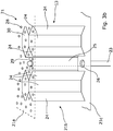
- the thermo-acoustic system 20 comprises an exchanger 22 connected to a fluid circuit 10 and through which the fluid L to be cooled passes, an acoustic attenuation structure 21 forming all or part of a wall 5b, 7b of the duct of the fan duct 200 and which is located at a distance from the exchanger 22, and an oscillating heat pipe 23 in the form of a tube 23a extending in a plane (for example a parallel plane or perpendicular to the motor axis X) between the exchanger 22 and the acoustic attenuation structure 21, the tube 23a having the shape of a coil with a plurality of bends 23b bent at 180 ° received alternately in the exchanger 22 and said structure 21.
- a plane for example a parallel plane or perpendicular to the motor axis X
- the acoustic attenuation structure 21 comprises a first panel 21a, a second panel 21c remote from the first panel 21a, and a core 21b interposed between the two panels 21a, 21c.
- the first panel 21a is directly in contact with the air flow P circulating in the fan duct 200 and has perforations 28 which are dimensioned so that part of the air flow P propelled by the blower 6a can penetrate. in the core 21b.
- the second panel 21c comprises orifices 26 for the passage of the heat pipe 2.
- the interface between the heat pipe 23 and the second panel 21 c at the level of the orifices 26 is sealed by the use of any suitable means such as, for example, a seal or sealant.
- the exchanger 22 is arranged in (the thickness of) the intervein 7, or else in (the thickness of) a bifurcation 8a, 8b.
- the exchanger 22 and the heat pipe 23 are arranged in the thickness of the intervein 7 and the acoustic attenuation structure 21 forms part of the outer wall 7b of the intervein 7.
- the exchanger 22 is in the form of a solid having a bottom wall 22a, called the bottom, and a wall forming a cover 22b, called a cover, parallel to one another and which are interconnected by four walls.
- side 22c two by two parallel, and all perpendicular to the bottom 22a and to the cover 22b.
- two side walls 22c are each equipped with a fluid connector 31 making it possible to connect a pipe 11 of the fluid circuit. 10 with which the exchanger 22 is associated and allowing the fluid L to enter or exit into or out of the exchanger 22.
- the fluid L of the fluid circuit 10 under the action of a pump (not shown) of said circuit, enters the exchanger 22 via a first fluidic connector 31, circulates in the exchanger 22 in a direction of fluidic circulation defined by the pump, and leaves the exchanger 22 via a second fluidic connector 31.
- the oscillating heat pipe 23 (also known by the acronym “PHP - pulsating heat pipe” for pulsed heat pipe) comprises a capillary tube 23 partially filled with heat transfer fluid naturally present in two phases, liquid and gas. This phase separation results mainly from surface tension forces.
- the elbows 23b of the heat pipe 23 arranged in the acoustic attenuation structure 21 are swept by the air flow P propelled by the blower 6a and the elbows 23b arranged in the exchanger 22 are bathed in the fluid L heated by the engine 6 ( oil extracted from the engine, or hydraulic fluid or kerosene to be cooled).
- the fluid L is oil
- the temperature in the exchanger 22 is 80 ° C while the temperature of the air flow P is of the order of 40 ° C.
- the heat pipe 23 is said to have an open loop, with its two blind ends.
- the heat pipe 23 shown comprises four elbows 23b received in the exchanger 22 and three elbows 23b received in the acoustic attenuation structure 23a.
- the blind ends of the heat pipe 23 are received in the sound attenuation structure 23a.
- the distance between the exchanger 22 and the acoustic attenuation structure 21 is, in this example, of the order of 30 to 50 cm.
- the efficiency of the heat pipe 23 increases with the increase in the number of elbows 23b.
- the heat pipe 23 comprises of the order of ten elbows, for example twelve, received in the exchanger 22 and of the order of ten elbows 23b, for example eleven, received in the structure sound attenuation 23a
- the heat pipe 23 passes through several orifices 26, the second panel 21c of the acoustic attenuation structure 21 and the elbows 23b are received in the acoustic attenuation structure 21 in being supported by supporting partitions 25.
- the heat pipe 23 passes through several orifices, one of the walls 22b of the exchanger 22 and the elbows 23b of the heat pipe 23 extend into the exchanger 22 so as to bathe in the fluid L outstanding.
- the heat pipe 23 extends in the exchanger, according to the configuration of the exchanger 22 and the heat pipe 23, for example, parallel or perpendicular to the direction of circulation of the fluid L,
- the air flow P flows along the first panel 21a of the sound attenuation structure 21 and the perforations 28 ensure the penetration of a part of the air P in the acoustic cavities 30.
- Each acoustic cavity 30 acts as a quarter-wave resonator and makes it possible to attenuate the sounds emitted by the circulation of the air in the fan duct 200.
- the elbows 23b of the heat pipe 23 arranged in the sound attenuation structure 21 are subjected to the temperature of the air flow P circulating in the fan duct 200. From a thermal point of view, considering the thermal circuit formed by the heat pipe 23 , the exchanger 22 and the acoustic attenuation structure 21, said structure forms a condenser.
- the elbows 23b of the heat pipe 23 arranged in the exchanger 22 are subjected to the temperature of the circulating fluid L. From a thermal point of view, considering the thermal circuit formed by the heat pipe 23, the exchanger 22 and the acoustic attenuation structure 21, the exchanger 22 forms an evaporator.
- the oscillating heat pipe fluid is cooled in the condenser and heated in the evaporator. Temperature gradients generate pressure fluctuations associated with generation, growth, and oscillation (the shape of the coil allows the oscillation of the vapor bubbles in the condenser. These fluctuations cause an oscillatory circulation of the fluid allowing the mass transport and therefore heat between the condenser and the evaporator.
- the invention makes it possible to integrate a fluid cooling system 20 into an acoustic attenuation structure 21 while deporting the fluid L to be regulated in temperature from the fan duct 200 in order to limit the risk of an uncontrolled leak in the latter.
- the heat transfer fluid located inside the tube 23a of the heat pipe 23 is a fluid compatible with aeronautical applications and extreme flight conditions (temperature, pressure, etc.), such as for example water, silver, lithium, sodium, ethanol, methanol.
- the heat transfer fluid filled, for example, 50% of the total interior volume of the tube 23a.
- the structural partitions and heat pipe support 24,25 of the acoustic attenuation structure 21 are made of a material having a strong thermal conduction, such as for example a metallic material.
- the exchanger 22 is made from a metallic material, such as, for example, titanium or aluminum, or even from a composite material.
- the fluid cooling system 20 comprises several heat pipes 23 as described above.
- the elbows 23b of the latter which are arranged in the acoustic attenuation structure 21 are preferably arranged in said structure in a repeating pattern in order to be able to automate the assembly of the heat pipes 23 with the acoustic attenuation structure 21 during of the manufacture of the latter.
- the heat pipe 23 is closed loop and then does not have a blind end.
- the heat pipe 23 comprises four elbows 23b received in the exchanger 22 and three elbows 23b received in the acoustic attenuation structure 21.
- a portion 23c, arranged in the acoustic attenuation structure, ensures the looping of the tube 23a.
Landscapes
- Engineering & Computer Science (AREA)
- Chemical & Material Sciences (AREA)
- Combustion & Propulsion (AREA)
- Mechanical Engineering (AREA)
- General Engineering & Computer Science (AREA)
- Physics & Mathematics (AREA)
- Acoustics & Sound (AREA)
- Multimedia (AREA)
- Heat-Exchange Devices With Radiators And Conduit Assemblies (AREA)
- Aviation & Aerospace Engineering (AREA)
- Structures Of Non-Positive Displacement Pumps (AREA)
Claims (9)
- Mantelstrom-Turbotriebwerk (4) für ein Luftfahrzeug, umfassend einen Motor (6), der dafür vorgesehen ist, ein Gebläse (6a) drehend anzutreiben; einen ringförmigen Raum zwischen Primär- und Sekundärstromkanal (7), der zum Motor (6) konzentrisch ist; eine Gondel (5), die zu dem Raum zwischen Primär- und Sekundärstromkanal (7) konzentrisch ist, wobei der Raum zwischen Primär- und Sekundärstromkanal und die Gondel zwischen sich einen Gebläsekanal (200) definieren, in welchem während der Drehung des Gebläses (6a) ein Luftstrom (P) strömt; wenigstens einen Fluidkreislauf (10), der dafür ausgelegt ist, ein Fluid (L) zum oder aus dem Motor (6) durchströmen zu lassen; wobei das Turbotriebwerk (4) ein thermoakustisches System (20) umfasst, das einem Fluidkreislauf (10) zugeordnet ist,
dadurch gekennzeichnet, dass das thermoakustische System (20) einen Austauscher (22), der mit einem Fluidkreislauf (10) verbunden ist und in welchem ein zu kühlendes Fluid (L) durchströmt, eine akustische Dämpfungsstruktur (21), die vollständig oder teilweise eine Wand (5b, 7b) des Kanals des Gebläsekanals (200) bildet, wobei sich diese Struktur in einem Abstand von dem Austauscher (22) befindet, und ein oszillierendes Wärmerohr (23) umfasst, welches ein Rohr (23a), das sich, in einer Ebene, zwischen dem Austauscher (22) und der akustischen Dämpfungsstruktur (21) erstreckt, umfasst, wobei das Rohr eine Schlangenform mit einer Vielzahl von um 180° gebogenen Winkelstücken (23b) aufweist, die abwechselnd in dem Austauscher (22) und in der Struktur (21) aufgenommen sind. - Turbotriebwerk (4) nach Anspruch 1, dadurch gekennzeichnet, dass das Wärmerohr (23) mit offenem Regelkreis betrieben wird.
- Turbotriebwerk (4) nach Anspruch 2, dadurch gekennzeichnet, dass das Wärmerohr (23) zwei geschlossene Enden umfasst.
- Turbotriebwerk (4) nach einem der Ansprüche 1 bis 3, dadurch gekennzeichnet, dass die akustische Dämpfungsstruktur (21) umfasst: eine erste Platte (21a), die mit dem im Gebläsekanal (200) strömenden Luftstrom (P) in Kontakt steht und Perforationen (28) aufweist; eine zweite Platte (21c), die mehrere Öffnungen (26) für den Durchgang des Wärmerohres (23) umfasst; einen Kern (21b), der mehrere strukturelle Trennwände (24) umfasst, die mit den zwei Platten (21a, 21c) ein Netz von akustischen Hohlräumen (30) bilden, das sich zwischen den zwei Platten (21a, 21c) erstreckt, und wobei jeder akustischen Hohlraum (30) mit dem Gebläsekanal (200) über die Perforationen (28) in Verbindung steht, wobei der Kern (21b) außerdem mehrere Stütztrennwände (25) der Winkelstücke (23b) des Wärmerohres (23) umfasst, wobei die Trennwände (25) die Winkelstücke (23b) des Wärmerohres (23) stützen, die in der akustischen Dämpfungsstruktur (21) aufgenommen sind.
- Turbotriebwerk (4) nach Anspruch 4, dadurch gekennzeichnet, dass jede der Stütztrennwände (25) an jeder der Platten (21a, 21c) befestigt ist und eine Öffnung (27) aufweist, durch welche das Wärmerohr (23) verläuft.
- Turbotriebwerk (4) nach Anspruch 4, dadurch gekennzeichnet, dass jede der Stütztrennwände (25) an der zweiten Platte (21c) befestigt ist und einen freien Rand (29) in einem Abstand von der ersten Platte (21a) aufweist, der dafür ausgebildet ist, das Winkelstück (23b) des Wärmerohres (23) aufzunehmen.
- Turbotriebwerk (4) nach Anspruch 4, dadurch gekennzeichnet, dass sich der Austauscher (22) in einem Abstand von der zweiten Platte (21c) befindet.
- Turbotriebwerk (4) nach einem der Ansprüche 1 bis 7, dadurch gekennzeichnet, dass der Austauscher (22) in dem Raum zwischen Primär- und Sekundärstromkanal (7) angeordnet ist.
- Turbotriebwerk (4) nach einem der Ansprüche 1 bis 7, wobei das Turbotriebwerk (4) zwei einander diametral gegenüberliegende Abzweigungen (8a, 8b) umfasst, welche die Gondel (5) und den Raum zwischen Primär- und Sekundärstromkanal (7) verbinden, dadurch gekennzeichnet, dass der Austauscher (22) in einer der Abzweigungen (8a, 8b) angeordnet ist.
Applications Claiming Priority (1)
| Application Number | Priority Date | Filing Date | Title |
|---|---|---|---|
| FR1871234A FR3087573A1 (fr) | 2018-10-19 | 2018-10-19 | Turbomachine equipee d’un systeme thermo-acoustique. |
Publications (2)
| Publication Number | Publication Date |
|---|---|
| EP3640467A1 EP3640467A1 (de) | 2020-04-22 |
| EP3640467B1 true EP3640467B1 (de) | 2021-05-19 |
Family
ID=65444232
Family Applications (1)
| Application Number | Title | Priority Date | Filing Date |
|---|---|---|---|
| EP19186990.8A Active EP3640467B1 (de) | 2018-10-19 | 2019-07-18 | Turbotriebwerk mit thermoakustischem system |
Country Status (4)
| Country | Link |
|---|---|
| US (1) | US11293348B2 (de) |
| EP (1) | EP3640467B1 (de) |
| CN (1) | CN111075604B (de) |
| FR (1) | FR3087573A1 (de) |
Families Citing this family (3)
| Publication number | Priority date | Publication date | Assignee | Title |
|---|---|---|---|---|
| FR3128778A1 (fr) * | 2021-11-04 | 2023-05-05 | Airbus Operations | Module assurant une atténuation d’ondes acoustiques et un échange thermique |
| FR3134375A1 (fr) * | 2022-04-08 | 2023-10-13 | Airbus Operations | Structure fixe interne pour aéronef comportant une structure en nid d’abeilles, un échangeur thermo-acoustique, un cadre et des moyens de fixation |
| FR3156486A1 (fr) | 2023-12-08 | 2025-06-13 | Airbus Operations (S.A.S.) | Ensemble propulsif d’un aeronef comprenant un circuit de refroidissement d’un fluide a raccords rapides nacelle/moteur et aeronef muni d’un tel ensemble |
Family Cites Families (13)
| Publication number | Priority date | Publication date | Assignee | Title |
|---|---|---|---|---|
| DE2510225C2 (de) * | 1974-03-11 | 1986-09-11 | Pall Corp., Glen Cove, N.Y. | Vorrichtung zum Abscheiden von in Gasen schwebenden Flüssigkeiten |
| EP2075194B1 (de) * | 2007-12-27 | 2017-08-16 | Techspace Aero | Luft-Öl-Wärmetauscher für ein Turbostrahltriebwerk, zugehöriges Turbostrahltriebwerk und Benutzung dieses Wärmetauschers |
| US8333552B2 (en) * | 2008-06-20 | 2012-12-18 | General Electric Company | Combined acoustic absorber and heat exchanging outlet guide vanes |
| US20130239542A1 (en) * | 2012-03-16 | 2013-09-19 | United Technologies Corporation | Structures and methods for intercooling aircraft gas turbine engines |
| US20140165570A1 (en) * | 2012-12-18 | 2014-06-19 | United Technologies Corporation | Oscillating heat pipe for thermal management of gas turbine engines |
| EP2942508B1 (de) * | 2014-05-08 | 2022-08-24 | Rolls-Royce North American Technologies, Inc. | Verbesserte kühlkörperverfügbarkeit auf gasturbinenmotoren durch verwendung von festkörperwärmepumpen |
| US20160017810A1 (en) * | 2014-07-21 | 2016-01-21 | United Technologies Corporation | Acoustic liner heat exchanger |
| EP3038101B1 (de) | 2014-12-23 | 2022-11-23 | Airbus (Sas) | Schalldämmwand mit integriertem Wärmetauscher |
| US9909448B2 (en) * | 2015-04-15 | 2018-03-06 | General Electric Company | Gas turbine engine component with integrated heat pipe |
| US10400675B2 (en) * | 2015-12-03 | 2019-09-03 | General Electric Company | Closed loop cooling method and system with heat pipes for a gas turbine engine |
| EP3244039A1 (de) * | 2016-05-10 | 2017-11-15 | Rolls-Royce Deutschland Ltd & Co KG | Wärmeaustauschsystem für ein lastgetriebe, lastgetriebe und turbomotor mit einem lastgetriebe |
| US10676205B2 (en) * | 2016-08-19 | 2020-06-09 | General Electric Company | Propulsion engine for an aircraft |
| US11262144B2 (en) * | 2017-12-29 | 2022-03-01 | General Electric Company | Diffuser integrated heat exchanger |
-
2018
- 2018-10-19 FR FR1871234A patent/FR3087573A1/fr not_active Ceased
-
2019
- 2019-07-18 EP EP19186990.8A patent/EP3640467B1/de active Active
- 2019-09-18 US US16/574,946 patent/US11293348B2/en active Active
- 2019-10-17 CN CN201910987829.8A patent/CN111075604B/zh active Active
Also Published As
| Publication number | Publication date |
|---|---|
| FR3087573A1 (fr) | 2020-04-24 |
| CN111075604A (zh) | 2020-04-28 |
| EP3640467A1 (de) | 2020-04-22 |
| CN111075604B (zh) | 2022-06-03 |
| US11293348B2 (en) | 2022-04-05 |
| US20200122852A1 (en) | 2020-04-23 |
Similar Documents
| Publication | Publication Date | Title |
|---|---|---|
| EP3859135B1 (de) | Turbotriebwerk für flugzeug mit thermoakustischem system | |
| EP3640467B1 (de) | Turbotriebwerk mit thermoakustischem system | |
| EP3707381B1 (de) | Flüssigkeitszirkulator mit welliger membran | |
| EP4166771B1 (de) | Antriebseinheit für ein flugzeug | |
| EP3405723B1 (de) | Kondensationswärmetauscher mit einer wärmetauschervorrichtung | |
| EP3640139A1 (de) | Motorgondel eines luftfahrzeugs, die mit einem vereisungs-schutzsystem ausgestattet ist | |
| EP1444473B1 (de) | Wärmetauschermodul mit hauptkühler und nebenkühler | |
| EP1558886B1 (de) | Verwaltungssystem für thermische Energie erzeugt durch einen Kraftfahrzeugwärmemotor | |
| WO2016102691A2 (fr) | Paroi acoustique à échangeur thermique intégré | |
| EP4124738B1 (de) | Antriebsanordnung für luftfahrzeug | |
| FR3041704A1 (fr) | Panneau d'echange thermique et de reduction de bruit pour un ensemble propulsif | |
| EP3719279B1 (de) | Oberflächenwärmetauscher für kühlsystem eines turbotriebwerks für luftfahrzeug | |
| EP3487764B1 (de) | Turbinenmotorgondel mit einer kühlvorrichtung | |
| FR2935475A1 (fr) | Echangeur de chaleur pour le refroidissement d'un fluide, en particulier des gaz d'echappement recircules d'un moteur thermique | |
| FR2902831A1 (fr) | Turboreacteur pour aeronef | |
| EP3719277B1 (de) | Wärmeübertragungsflüssigkeit für kühlsystem eines turbotriebwerks für luftfahrzeug | |
| EP3975677A1 (de) | Elektrisches leistungsmodul mit einem kühlsystem | |
| FR2915520A1 (fr) | Ensemble moteur comprenant un ou plusieurs caloducs pour le refroidissement d'un compresseur haute pression | |
| FR3032027A1 (fr) | Boucle diphasique de refroidissement a evaporateurs satellites | |
| FR2552216A1 (fr) | Perfectionnements apportes aux tubes echangeurs de chaleur et aux echangeurs realises avec de tels tubes | |
| FR3115332A1 (fr) | Pompe comprenant des moyens de refroidissement | |
| CA3099889A1 (fr) | Dispositif de refroidissement d'un carter de turbomachine | |
| FR2484619A1 (fr) | Echangeur tubulaire a detente directe pour la vinification | |
| WO2024028551A1 (fr) | Système d'échappement pour turbomachine comprenant un échangeur de chaleur | |
| EP2865960A1 (de) | Vorrichtung für den Wärmeaustausch |
Legal Events
| Date | Code | Title | Description |
|---|---|---|---|
| PUAI | Public reference made under article 153(3) epc to a published international application that has entered the european phase |
Free format text: ORIGINAL CODE: 0009012 |
|
| STAA | Information on the status of an ep patent application or granted ep patent |
Free format text: STATUS: REQUEST FOR EXAMINATION WAS MADE |
|
| 17P | Request for examination filed |
Effective date: 20190718 |
|
| AK | Designated contracting states |
Kind code of ref document: A1 Designated state(s): AL AT BE BG CH CY CZ DE DK EE ES FI FR GB GR HR HU IE IS IT LI LT LU LV MC MK MT NL NO PL PT RO RS SE SI SK SM TR |
|
| RBV | Designated contracting states (corrected) |
Designated state(s): AL AT BE BG CH CY CZ DE DK EE ES FI FR GB GR HR HU IE IS IT LI LT LU LV MC MK MT NL NO PL PT RO RS SE SI SK SM TR |
|
| GRAP | Despatch of communication of intention to grant a patent |
Free format text: ORIGINAL CODE: EPIDOSNIGR1 |
|
| STAA | Information on the status of an ep patent application or granted ep patent |
Free format text: STATUS: GRANT OF PATENT IS INTENDED |
|
| INTG | Intention to grant announced |
Effective date: 20210218 |
|
| GRAS | Grant fee paid |
Free format text: ORIGINAL CODE: EPIDOSNIGR3 |
|
| GRAA | (expected) grant |
Free format text: ORIGINAL CODE: 0009210 |
|
| STAA | Information on the status of an ep patent application or granted ep patent |
Free format text: STATUS: THE PATENT HAS BEEN GRANTED |
|
| AK | Designated contracting states |
Kind code of ref document: B1 Designated state(s): AL AT BE BG CH CY CZ DE DK EE ES FI FR GB GR HR HU IE IS IT LI LT LU LV MC MK MT NL NO PL PT RO RS SE SI SK SM TR |
|
| REG | Reference to a national code |
Ref country code: GB Ref legal event code: FG4D Free format text: NOT ENGLISH |
|
| REG | Reference to a national code |
Ref country code: CH Ref legal event code: EP |
|
| REG | Reference to a national code |
Ref country code: DE Ref legal event code: R096 Ref document number: 602019004671 Country of ref document: DE |
|
| REG | Reference to a national code |
Ref country code: AT Ref legal event code: REF Ref document number: 1394202 Country of ref document: AT Kind code of ref document: T Effective date: 20210615 |
|
| REG | Reference to a national code |
Ref country code: IE Ref legal event code: FG4D Free format text: LANGUAGE OF EP DOCUMENT: FRENCH |
|
| REG | Reference to a national code |
Ref country code: LT Ref legal event code: MG9D |
|
| REG | Reference to a national code |
Ref country code: AT Ref legal event code: MK05 Ref document number: 1394202 Country of ref document: AT Kind code of ref document: T Effective date: 20210519 |
|
| REG | Reference to a national code |
Ref country code: NL Ref legal event code: MP Effective date: 20210519 |
|
| PG25 | Lapsed in a contracting state [announced via postgrant information from national office to epo] |
Ref country code: LT Free format text: LAPSE BECAUSE OF FAILURE TO SUBMIT A TRANSLATION OF THE DESCRIPTION OR TO PAY THE FEE WITHIN THE PRESCRIBED TIME-LIMIT Effective date: 20210519 Ref country code: HR Free format text: LAPSE BECAUSE OF FAILURE TO SUBMIT A TRANSLATION OF THE DESCRIPTION OR TO PAY THE FEE WITHIN THE PRESCRIBED TIME-LIMIT Effective date: 20210519 Ref country code: FI Free format text: LAPSE BECAUSE OF FAILURE TO SUBMIT A TRANSLATION OF THE DESCRIPTION OR TO PAY THE FEE WITHIN THE PRESCRIBED TIME-LIMIT Effective date: 20210519 Ref country code: BG Free format text: LAPSE BECAUSE OF FAILURE TO SUBMIT A TRANSLATION OF THE DESCRIPTION OR TO PAY THE FEE WITHIN THE PRESCRIBED TIME-LIMIT Effective date: 20210819 Ref country code: AT Free format text: LAPSE BECAUSE OF FAILURE TO SUBMIT A TRANSLATION OF THE DESCRIPTION OR TO PAY THE FEE WITHIN THE PRESCRIBED TIME-LIMIT Effective date: 20210519 |
|
| PG25 | Lapsed in a contracting state [announced via postgrant information from national office to epo] |
Ref country code: PL Free format text: LAPSE BECAUSE OF FAILURE TO SUBMIT A TRANSLATION OF THE DESCRIPTION OR TO PAY THE FEE WITHIN THE PRESCRIBED TIME-LIMIT Effective date: 20210519 Ref country code: NO Free format text: LAPSE BECAUSE OF FAILURE TO SUBMIT A TRANSLATION OF THE DESCRIPTION OR TO PAY THE FEE WITHIN THE PRESCRIBED TIME-LIMIT Effective date: 20210819 Ref country code: LV Free format text: LAPSE BECAUSE OF FAILURE TO SUBMIT A TRANSLATION OF THE DESCRIPTION OR TO PAY THE FEE WITHIN THE PRESCRIBED TIME-LIMIT Effective date: 20210519 Ref country code: SE Free format text: LAPSE BECAUSE OF FAILURE TO SUBMIT A TRANSLATION OF THE DESCRIPTION OR TO PAY THE FEE WITHIN THE PRESCRIBED TIME-LIMIT Effective date: 20210519 Ref country code: PT Free format text: LAPSE BECAUSE OF FAILURE TO SUBMIT A TRANSLATION OF THE DESCRIPTION OR TO PAY THE FEE WITHIN THE PRESCRIBED TIME-LIMIT Effective date: 20210920 Ref country code: RS Free format text: LAPSE BECAUSE OF FAILURE TO SUBMIT A TRANSLATION OF THE DESCRIPTION OR TO PAY THE FEE WITHIN THE PRESCRIBED TIME-LIMIT Effective date: 20210519 Ref country code: IS Free format text: LAPSE BECAUSE OF FAILURE TO SUBMIT A TRANSLATION OF THE DESCRIPTION OR TO PAY THE FEE WITHIN THE PRESCRIBED TIME-LIMIT Effective date: 20210919 Ref country code: GR Free format text: LAPSE BECAUSE OF FAILURE TO SUBMIT A TRANSLATION OF THE DESCRIPTION OR TO PAY THE FEE WITHIN THE PRESCRIBED TIME-LIMIT Effective date: 20210820 |
|
| PG25 | Lapsed in a contracting state [announced via postgrant information from national office to epo] |
Ref country code: NL Free format text: LAPSE BECAUSE OF FAILURE TO SUBMIT A TRANSLATION OF THE DESCRIPTION OR TO PAY THE FEE WITHIN THE PRESCRIBED TIME-LIMIT Effective date: 20210519 |
|
| PG25 | Lapsed in a contracting state [announced via postgrant information from national office to epo] |
Ref country code: EE Free format text: LAPSE BECAUSE OF FAILURE TO SUBMIT A TRANSLATION OF THE DESCRIPTION OR TO PAY THE FEE WITHIN THE PRESCRIBED TIME-LIMIT Effective date: 20210519 Ref country code: ES Free format text: LAPSE BECAUSE OF FAILURE TO SUBMIT A TRANSLATION OF THE DESCRIPTION OR TO PAY THE FEE WITHIN THE PRESCRIBED TIME-LIMIT Effective date: 20210519 Ref country code: SK Free format text: LAPSE BECAUSE OF FAILURE TO SUBMIT A TRANSLATION OF THE DESCRIPTION OR TO PAY THE FEE WITHIN THE PRESCRIBED TIME-LIMIT Effective date: 20210519 Ref country code: DK Free format text: LAPSE BECAUSE OF FAILURE TO SUBMIT A TRANSLATION OF THE DESCRIPTION OR TO PAY THE FEE WITHIN THE PRESCRIBED TIME-LIMIT Effective date: 20210519 Ref country code: CZ Free format text: LAPSE BECAUSE OF FAILURE TO SUBMIT A TRANSLATION OF THE DESCRIPTION OR TO PAY THE FEE WITHIN THE PRESCRIBED TIME-LIMIT Effective date: 20210519 Ref country code: RO Free format text: LAPSE BECAUSE OF FAILURE TO SUBMIT A TRANSLATION OF THE DESCRIPTION OR TO PAY THE FEE WITHIN THE PRESCRIBED TIME-LIMIT Effective date: 20210519 Ref country code: SM Free format text: LAPSE BECAUSE OF FAILURE TO SUBMIT A TRANSLATION OF THE DESCRIPTION OR TO PAY THE FEE WITHIN THE PRESCRIBED TIME-LIMIT Effective date: 20210519 |
|
| REG | Reference to a national code |
Ref country code: DE Ref legal event code: R097 Ref document number: 602019004671 Country of ref document: DE |
|
| PLBE | No opposition filed within time limit |
Free format text: ORIGINAL CODE: 0009261 |
|
| STAA | Information on the status of an ep patent application or granted ep patent |
Free format text: STATUS: NO OPPOSITION FILED WITHIN TIME LIMIT |
|
| PG25 | Lapsed in a contracting state [announced via postgrant information from national office to epo] |
Ref country code: MC Free format text: LAPSE BECAUSE OF FAILURE TO SUBMIT A TRANSLATION OF THE DESCRIPTION OR TO PAY THE FEE WITHIN THE PRESCRIBED TIME-LIMIT Effective date: 20210519 |
|
| REG | Reference to a national code |
Ref country code: BE Ref legal event code: MM Effective date: 20210731 |
|
| 26N | No opposition filed |
Effective date: 20220222 |
|
| PG25 | Lapsed in a contracting state [announced via postgrant information from national office to epo] |
Ref country code: IS Free format text: LAPSE BECAUSE OF FAILURE TO SUBMIT A TRANSLATION OF THE DESCRIPTION OR TO PAY THE FEE WITHIN THE PRESCRIBED TIME-LIMIT Effective date: 20210919 Ref country code: LU Free format text: LAPSE BECAUSE OF NON-PAYMENT OF DUE FEES Effective date: 20210718 Ref country code: AL Free format text: LAPSE BECAUSE OF FAILURE TO SUBMIT A TRANSLATION OF THE DESCRIPTION OR TO PAY THE FEE WITHIN THE PRESCRIBED TIME-LIMIT Effective date: 20210519 |
|
| PG25 | Lapsed in a contracting state [announced via postgrant information from national office to epo] |
Ref country code: IT Free format text: LAPSE BECAUSE OF FAILURE TO SUBMIT A TRANSLATION OF THE DESCRIPTION OR TO PAY THE FEE WITHIN THE PRESCRIBED TIME-LIMIT Effective date: 20210519 Ref country code: IE Free format text: LAPSE BECAUSE OF NON-PAYMENT OF DUE FEES Effective date: 20210718 Ref country code: BE Free format text: LAPSE BECAUSE OF NON-PAYMENT OF DUE FEES Effective date: 20210731 |
|
| REG | Reference to a national code |
Ref country code: CH Ref legal event code: PL |
|
| PG25 | Lapsed in a contracting state [announced via postgrant information from national office to epo] |
Ref country code: LI Free format text: LAPSE BECAUSE OF NON-PAYMENT OF DUE FEES Effective date: 20220731 Ref country code: CH Free format text: LAPSE BECAUSE OF NON-PAYMENT OF DUE FEES Effective date: 20220731 |
|
| PG25 | Lapsed in a contracting state [announced via postgrant information from national office to epo] |
Ref country code: CY Free format text: LAPSE BECAUSE OF FAILURE TO SUBMIT A TRANSLATION OF THE DESCRIPTION OR TO PAY THE FEE WITHIN THE PRESCRIBED TIME-LIMIT Effective date: 20210519 |
|
| PG25 | Lapsed in a contracting state [announced via postgrant information from national office to epo] |
Ref country code: HU Free format text: LAPSE BECAUSE OF FAILURE TO SUBMIT A TRANSLATION OF THE DESCRIPTION OR TO PAY THE FEE WITHIN THE PRESCRIBED TIME-LIMIT; INVALID AB INITIO Effective date: 20190718 |
|
| PG25 | Lapsed in a contracting state [announced via postgrant information from national office to epo] |
Ref country code: MK Free format text: LAPSE BECAUSE OF FAILURE TO SUBMIT A TRANSLATION OF THE DESCRIPTION OR TO PAY THE FEE WITHIN THE PRESCRIBED TIME-LIMIT Effective date: 20210519 |
|
| PG25 | Lapsed in a contracting state [announced via postgrant information from national office to epo] |
Ref country code: TR Free format text: LAPSE BECAUSE OF FAILURE TO SUBMIT A TRANSLATION OF THE DESCRIPTION OR TO PAY THE FEE WITHIN THE PRESCRIBED TIME-LIMIT Effective date: 20210519 |
|
| PG25 | Lapsed in a contracting state [announced via postgrant information from national office to epo] |
Ref country code: MT Free format text: LAPSE BECAUSE OF FAILURE TO SUBMIT A TRANSLATION OF THE DESCRIPTION OR TO PAY THE FEE WITHIN THE PRESCRIBED TIME-LIMIT Effective date: 20210519 |
|
| PGFP | Annual fee paid to national office [announced via postgrant information from national office to epo] |
Ref country code: DE Payment date: 20250722 Year of fee payment: 7 |
|
| PGFP | Annual fee paid to national office [announced via postgrant information from national office to epo] |
Ref country code: GB Payment date: 20250722 Year of fee payment: 7 |
|
| PGFP | Annual fee paid to national office [announced via postgrant information from national office to epo] |
Ref country code: FR Payment date: 20250725 Year of fee payment: 7 |