EP3640467B1 - Turbomachine equipee d'un systeme thermo-acoustique - Google Patents
Turbomachine equipee d'un systeme thermo-acoustique Download PDFInfo
- Publication number
- EP3640467B1 EP3640467B1 EP19186990.8A EP19186990A EP3640467B1 EP 3640467 B1 EP3640467 B1 EP 3640467B1 EP 19186990 A EP19186990 A EP 19186990A EP 3640467 B1 EP3640467 B1 EP 3640467B1
- Authority
- EP
- European Patent Office
- Prior art keywords
- turbomachine
- heat pipe
- exchanger
- acoustic
- panel
- Prior art date
- Legal status (The legal status is an assumption and is not a legal conclusion. Google has not performed a legal analysis and makes no representation as to the accuracy of the status listed.)
- Active
Links
- 239000012530 fluid Substances 0.000 claims description 40
- 238000005192 partition Methods 0.000 claims description 13
- 230000005534 acoustic noise Effects 0.000 claims 1
- 238000001816 cooling Methods 0.000 description 4
- 239000003350 kerosene Substances 0.000 description 4
- OKKJLVBELUTLKV-UHFFFAOYSA-N Methanol Chemical compound OC OKKJLVBELUTLKV-UHFFFAOYSA-N 0.000 description 3
- 239000013529 heat transfer fluid Substances 0.000 description 3
- LFQSCWFLJHTTHZ-UHFFFAOYSA-N Ethanol Chemical compound CCO LFQSCWFLJHTTHZ-UHFFFAOYSA-N 0.000 description 2
- 239000007769 metal material Substances 0.000 description 2
- 230000010355 oscillation Effects 0.000 description 2
- DGAQECJNVWCQMB-PUAWFVPOSA-M Ilexoside XXIX Chemical compound C[C@@H]1CC[C@@]2(CC[C@@]3(C(=CC[C@H]4[C@]3(CC[C@@H]5[C@@]4(CC[C@@H](C5(C)C)OS(=O)(=O)[O-])C)C)[C@@H]2[C@]1(C)O)C)C(=O)O[C@H]6[C@@H]([C@H]([C@@H]([C@H](O6)CO)O)O)O.[Na+] DGAQECJNVWCQMB-PUAWFVPOSA-M 0.000 description 1
- WHXSMMKQMYFTQS-UHFFFAOYSA-N Lithium Chemical compound [Li] WHXSMMKQMYFTQS-UHFFFAOYSA-N 0.000 description 1
- BQCADISMDOOEFD-UHFFFAOYSA-N Silver Chemical compound [Ag] BQCADISMDOOEFD-UHFFFAOYSA-N 0.000 description 1
- RTAQQCXQSZGOHL-UHFFFAOYSA-N Titanium Chemical compound [Ti] RTAQQCXQSZGOHL-UHFFFAOYSA-N 0.000 description 1
- XAGFODPZIPBFFR-UHFFFAOYSA-N aluminium Chemical compound [Al] XAGFODPZIPBFFR-UHFFFAOYSA-N 0.000 description 1
- 229910052782 aluminium Inorganic materials 0.000 description 1
- 239000002131 composite material Substances 0.000 description 1
- 229940082150 encore Drugs 0.000 description 1
- -1 for example Substances 0.000 description 1
- 239000007788 liquid Substances 0.000 description 1
- 229910052744 lithium Inorganic materials 0.000 description 1
- 238000004519 manufacturing process Methods 0.000 description 1
- 239000000463 material Substances 0.000 description 1
- 230000003534 oscillatory effect Effects 0.000 description 1
- 230000035515 penetration Effects 0.000 description 1
- 238000005191 phase separation Methods 0.000 description 1
- 230000001105 regulatory effect Effects 0.000 description 1
- 239000000565 sealant Substances 0.000 description 1
- 239000004332 silver Substances 0.000 description 1
- 229910052709 silver Inorganic materials 0.000 description 1
- 239000011734 sodium Substances 0.000 description 1
- 229910052708 sodium Inorganic materials 0.000 description 1
- 239000007787 solid Substances 0.000 description 1
- 229910052719 titanium Inorganic materials 0.000 description 1
- 239000010936 titanium Substances 0.000 description 1
- 238000011144 upstream manufacturing Methods 0.000 description 1
- 210000003462 vein Anatomy 0.000 description 1
- XLYOFNOQVPJJNP-UHFFFAOYSA-N water Substances O XLYOFNOQVPJJNP-UHFFFAOYSA-N 0.000 description 1
- 229910001868 water Inorganic materials 0.000 description 1
Images


Classifications
-
- F—MECHANICAL ENGINEERING; LIGHTING; HEATING; WEAPONS; BLASTING
- F02—COMBUSTION ENGINES; HOT-GAS OR COMBUSTION-PRODUCT ENGINE PLANTS
- F02C—GAS-TURBINE PLANTS; AIR INTAKES FOR JET-PROPULSION PLANTS; CONTROLLING FUEL SUPPLY IN AIR-BREATHING JET-PROPULSION PLANTS
- F02C7/00—Features, components parts, details or accessories, not provided for in, or of interest apart form groups F02C1/00 - F02C6/00; Air intakes for jet-propulsion plants
- F02C7/12—Cooling of plants
- F02C7/14—Cooling of plants of fluids in the plant, e.g. lubricant or fuel
-
- F—MECHANICAL ENGINEERING; LIGHTING; HEATING; WEAPONS; BLASTING
- F02—COMBUSTION ENGINES; HOT-GAS OR COMBUSTION-PRODUCT ENGINE PLANTS
- F02C—GAS-TURBINE PLANTS; AIR INTAKES FOR JET-PROPULSION PLANTS; CONTROLLING FUEL SUPPLY IN AIR-BREATHING JET-PROPULSION PLANTS
- F02C7/00—Features, components parts, details or accessories, not provided for in, or of interest apart form groups F02C1/00 - F02C6/00; Air intakes for jet-propulsion plants
- F02C7/24—Heat or noise insulation
-
- F—MECHANICAL ENGINEERING; LIGHTING; HEATING; WEAPONS; BLASTING
- F02—COMBUSTION ENGINES; HOT-GAS OR COMBUSTION-PRODUCT ENGINE PLANTS
- F02K—JET-PROPULSION PLANTS
- F02K1/00—Plants characterised by the form or arrangement of the jet pipe or nozzle; Jet pipes or nozzles peculiar thereto
- F02K1/78—Other construction of jet pipes
- F02K1/82—Jet pipe walls, e.g. liners
- F02K1/827—Sound absorbing structures or liners
-
- F—MECHANICAL ENGINEERING; LIGHTING; HEATING; WEAPONS; BLASTING
- F02—COMBUSTION ENGINES; HOT-GAS OR COMBUSTION-PRODUCT ENGINE PLANTS
- F02K—JET-PROPULSION PLANTS
- F02K3/00—Plants including a gas turbine driving a compressor or a ducted fan
- F02K3/02—Plants including a gas turbine driving a compressor or a ducted fan in which part of the working fluid by-passes the turbine and combustion chamber
- F02K3/04—Plants including a gas turbine driving a compressor or a ducted fan in which part of the working fluid by-passes the turbine and combustion chamber the plant including ducted fans, i.e. fans with high volume, low pressure outputs, for augmenting the jet thrust, e.g. of double-flow type
- F02K3/06—Plants including a gas turbine driving a compressor or a ducted fan in which part of the working fluid by-passes the turbine and combustion chamber the plant including ducted fans, i.e. fans with high volume, low pressure outputs, for augmenting the jet thrust, e.g. of double-flow type with front fan
-
- G—PHYSICS
- G10—MUSICAL INSTRUMENTS; ACOUSTICS
- G10K—SOUND-PRODUCING DEVICES; METHODS OR DEVICES FOR PROTECTING AGAINST, OR FOR DAMPING, NOISE OR OTHER ACOUSTIC WAVES IN GENERAL; ACOUSTICS NOT OTHERWISE PROVIDED FOR
- G10K11/00—Methods or devices for transmitting, conducting or directing sound in general; Methods or devices for protecting against, or for damping, noise or other acoustic waves in general
- G10K11/16—Methods or devices for protecting against, or for damping, noise or other acoustic waves in general
- G10K11/172—Methods or devices for protecting against, or for damping, noise or other acoustic waves in general using resonance effects
-
- F—MECHANICAL ENGINEERING; LIGHTING; HEATING; WEAPONS; BLASTING
- F05—INDEXING SCHEMES RELATING TO ENGINES OR PUMPS IN VARIOUS SUBCLASSES OF CLASSES F01-F04
- F05D—INDEXING SCHEME FOR ASPECTS RELATING TO NON-POSITIVE-DISPLACEMENT MACHINES OR ENGINES, GAS-TURBINES OR JET-PROPULSION PLANTS
- F05D2260/00—Function
- F05D2260/20—Heat transfer, e.g. cooling
- F05D2260/208—Heat transfer, e.g. cooling using heat pipes
-
- F—MECHANICAL ENGINEERING; LIGHTING; HEATING; WEAPONS; BLASTING
- F05—INDEXING SCHEMES RELATING TO ENGINES OR PUMPS IN VARIOUS SUBCLASSES OF CLASSES F01-F04
- F05D—INDEXING SCHEME FOR ASPECTS RELATING TO NON-POSITIVE-DISPLACEMENT MACHINES OR ENGINES, GAS-TURBINES OR JET-PROPULSION PLANTS
- F05D2260/00—Function
- F05D2260/20—Heat transfer, e.g. cooling
- F05D2260/213—Heat transfer, e.g. cooling by the provision of a heat exchanger within the cooling circuit
-
- F—MECHANICAL ENGINEERING; LIGHTING; HEATING; WEAPONS; BLASTING
- F05—INDEXING SCHEMES RELATING TO ENGINES OR PUMPS IN VARIOUS SUBCLASSES OF CLASSES F01-F04
- F05D—INDEXING SCHEME FOR ASPECTS RELATING TO NON-POSITIVE-DISPLACEMENT MACHINES OR ENGINES, GAS-TURBINES OR JET-PROPULSION PLANTS
- F05D2260/00—Function
- F05D2260/96—Preventing, counteracting or reducing vibration or noise
- F05D2260/963—Preventing, counteracting or reducing vibration or noise by Helmholtz resonators
Definitions
- the present invention relates to a turbomachine for an aircraft equipped with a thermo-acoustic system for cooling the fluids necessary for the operation of the turbomachine as well as for attenuating the sounds emitted during said operation.
- a double-flow turbomachine has a fan duct, through which the air blown by the fan of the turbomachine passes to finally be ejected at the level of the exhaust of the turbomachine.
- the blower duct is delimited by walls which channel the air. These walls are formed of acoustic attenuation structures providing attenuation of the acoustic waves generated by the flow of air in the fan duct and thus make it possible to attenuate the noise of the turbomachine.
- the walls can also be equipped with heat exchangers used to achieve a heat exchange between the air circulating in the fan duct and pipes transporting flammable fluids allowing the operation of the turbomachine (oil, kerosene) in order to cool the latter.
- thermo-acoustic system comprising an acoustic attenuation structure in which pipes carrying fluids to be cooled are arranged.
- the sound attenuation structure includes perforations allowing air from the fan duct to penetrate its thickness in order to cool the pipes and therefore the fluids.
- One of the objectives of the present invention is to find an alternative solution to the thermo-acoustic system of the type described above.
- the invention relates to a bypass turbine engine for an aircraft as claimed in claim 1.
- a bypass turbomachine 4 of an aircraft (not shown) comprises an annular nacelle 5, centered on a longitudinal axis X (called the engine axis) and surrounding an engine 6.
- the engine 6 comprises, from upstream to downstream and centered on the engine axis X, a fan 6a, an engine body 6b.
- the body of the motor 6b comprises elements enabling the blower 6a to be turned when the motor 6 is started.
- the turbomachine 4 further comprises, downstream of the fan 6a, an annular intervein 7 concentric with the body of the engine 6.
- the intervein 7 comprises an internal wall 7a which defines with the engine 6 an annular hot air flow vein. 100 which extends along the motor axis X.
- the engine 6 is fixed to the nacelle 5 by means of two diametrically opposed bifurcations 8a, 8b which make it possible to ensure a mechanical cohesion of the turbomachine 5 and in particular connect the nacelle 5 and the intervein 7 to one another.
- the nacelle 5 comprises an outer wall 5a and an inner wall 5b and constitutes the outer casing of the turbomachine 5.
- the nacelle 5 surrounds the intervein 7 with which it is concentric.
- the outer wall 5a of the nacelle 5 forms the outer wall of the turbomachine 1 while the inner wall 5b of the nacelle 5 forms, with the outer wall 7b of the intervein 7, the walls of a fan duct 200 which s 'extends along the motor axis X and which receives the majority of the air flow P ejected by the fan 6a during the rotation of the latter.
- the blower duct 200 extends to the rear of the nacelle 5 where the air is ejected.
- the turbomachine 4 comprises different fluid circuits 10 for supplying the engine 6 with fluids L (not shown in figure 1 ) flammables necessary for its operation, such as, for example, kerosene, oil or hydraulic fluid.
- Each fluid circuit 10 comprises in particular pipes 11 in which the fluid L circulates, towards or out of the motor 6 and which are arranged in the thickness of the intervein 7 of the nacelle 5 or of a bifurcation 8a, 8b.
- a single fluid circuit 10 is shown, in part, by way of example: it is the oil circuit which is arranged in the interveine 7 to circulate oil in the engine 6 in order to cool it. .
- the operation of the engine 6 generates a rise in temperature of the fluids L.
- the oil extracted from the engine 6 must be cooled before reinjecting it into the engine 6, or else the kerosene or the hydraulic fluid heats up in the environment close to engine 6 and must be cooled).
- the operation of the motor 6 further generates the emission of unwanted sounds caused by the flow of the air flow P in the fan duct 200.
- the turbomachine 4 comprises a thermo-acoustic system 20 associated with at least one fluid circuit 10 and which is configured to achieve acoustic attenuation of the sounds emitted during operation of the engine 6 and cooling of the fluid L of the fluid circuit 10.
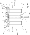
- the thermo-acoustic system 20 comprises an exchanger 22 connected to a fluid circuit 10 and through which the fluid L to be cooled passes, an acoustic attenuation structure 21 forming all or part of a wall 5b, 7b of the duct of the fan duct 200 and which is located at a distance from the exchanger 22, and an oscillating heat pipe 23 in the form of a tube 23a extending in a plane (for example a parallel plane or perpendicular to the motor axis X) between the exchanger 22 and the acoustic attenuation structure 21, the tube 23a having the shape of a coil with a plurality of bends 23b bent at 180 ° received alternately in the exchanger 22 and said structure 21.
- a plane for example a parallel plane or perpendicular to the motor axis X
- the acoustic attenuation structure 21 comprises a first panel 21a, a second panel 21c remote from the first panel 21a, and a core 21b interposed between the two panels 21a, 21c.
- the first panel 21a is directly in contact with the air flow P circulating in the fan duct 200 and has perforations 28 which are dimensioned so that part of the air flow P propelled by the blower 6a can penetrate. in the core 21b.
- the second panel 21c comprises orifices 26 for the passage of the heat pipe 2.
- the interface between the heat pipe 23 and the second panel 21 c at the level of the orifices 26 is sealed by the use of any suitable means such as, for example, a seal or sealant.
- the exchanger 22 is arranged in (the thickness of) the intervein 7, or else in (the thickness of) a bifurcation 8a, 8b.
- the exchanger 22 and the heat pipe 23 are arranged in the thickness of the intervein 7 and the acoustic attenuation structure 21 forms part of the outer wall 7b of the intervein 7.
- the exchanger 22 is in the form of a solid having a bottom wall 22a, called the bottom, and a wall forming a cover 22b, called a cover, parallel to one another and which are interconnected by four walls.
- side 22c two by two parallel, and all perpendicular to the bottom 22a and to the cover 22b.
- two side walls 22c are each equipped with a fluid connector 31 making it possible to connect a pipe 11 of the fluid circuit. 10 with which the exchanger 22 is associated and allowing the fluid L to enter or exit into or out of the exchanger 22.
- the fluid L of the fluid circuit 10 under the action of a pump (not shown) of said circuit, enters the exchanger 22 via a first fluidic connector 31, circulates in the exchanger 22 in a direction of fluidic circulation defined by the pump, and leaves the exchanger 22 via a second fluidic connector 31.
- the oscillating heat pipe 23 (also known by the acronym “PHP - pulsating heat pipe” for pulsed heat pipe) comprises a capillary tube 23 partially filled with heat transfer fluid naturally present in two phases, liquid and gas. This phase separation results mainly from surface tension forces.
- the elbows 23b of the heat pipe 23 arranged in the acoustic attenuation structure 21 are swept by the air flow P propelled by the blower 6a and the elbows 23b arranged in the exchanger 22 are bathed in the fluid L heated by the engine 6 ( oil extracted from the engine, or hydraulic fluid or kerosene to be cooled).
- the fluid L is oil
- the temperature in the exchanger 22 is 80 ° C while the temperature of the air flow P is of the order of 40 ° C.
- the heat pipe 23 is said to have an open loop, with its two blind ends.
- the heat pipe 23 shown comprises four elbows 23b received in the exchanger 22 and three elbows 23b received in the acoustic attenuation structure 23a.
- the blind ends of the heat pipe 23 are received in the sound attenuation structure 23a.
- the distance between the exchanger 22 and the acoustic attenuation structure 21 is, in this example, of the order of 30 to 50 cm.
- the efficiency of the heat pipe 23 increases with the increase in the number of elbows 23b.
- the heat pipe 23 comprises of the order of ten elbows, for example twelve, received in the exchanger 22 and of the order of ten elbows 23b, for example eleven, received in the structure sound attenuation 23a
- the heat pipe 23 passes through several orifices 26, the second panel 21c of the acoustic attenuation structure 21 and the elbows 23b are received in the acoustic attenuation structure 21 in being supported by supporting partitions 25.
- the heat pipe 23 passes through several orifices, one of the walls 22b of the exchanger 22 and the elbows 23b of the heat pipe 23 extend into the exchanger 22 so as to bathe in the fluid L outstanding.
- the heat pipe 23 extends in the exchanger, according to the configuration of the exchanger 22 and the heat pipe 23, for example, parallel or perpendicular to the direction of circulation of the fluid L,
- the air flow P flows along the first panel 21a of the sound attenuation structure 21 and the perforations 28 ensure the penetration of a part of the air P in the acoustic cavities 30.
- Each acoustic cavity 30 acts as a quarter-wave resonator and makes it possible to attenuate the sounds emitted by the circulation of the air in the fan duct 200.
- the elbows 23b of the heat pipe 23 arranged in the sound attenuation structure 21 are subjected to the temperature of the air flow P circulating in the fan duct 200. From a thermal point of view, considering the thermal circuit formed by the heat pipe 23 , the exchanger 22 and the acoustic attenuation structure 21, said structure forms a condenser.
- the elbows 23b of the heat pipe 23 arranged in the exchanger 22 are subjected to the temperature of the circulating fluid L. From a thermal point of view, considering the thermal circuit formed by the heat pipe 23, the exchanger 22 and the acoustic attenuation structure 21, the exchanger 22 forms an evaporator.
- the oscillating heat pipe fluid is cooled in the condenser and heated in the evaporator. Temperature gradients generate pressure fluctuations associated with generation, growth, and oscillation (the shape of the coil allows the oscillation of the vapor bubbles in the condenser. These fluctuations cause an oscillatory circulation of the fluid allowing the mass transport and therefore heat between the condenser and the evaporator.
- the invention makes it possible to integrate a fluid cooling system 20 into an acoustic attenuation structure 21 while deporting the fluid L to be regulated in temperature from the fan duct 200 in order to limit the risk of an uncontrolled leak in the latter.
- the heat transfer fluid located inside the tube 23a of the heat pipe 23 is a fluid compatible with aeronautical applications and extreme flight conditions (temperature, pressure, etc.), such as for example water, silver, lithium, sodium, ethanol, methanol.
- the heat transfer fluid filled, for example, 50% of the total interior volume of the tube 23a.
- the structural partitions and heat pipe support 24,25 of the acoustic attenuation structure 21 are made of a material having a strong thermal conduction, such as for example a metallic material.
- the exchanger 22 is made from a metallic material, such as, for example, titanium or aluminum, or even from a composite material.
- the fluid cooling system 20 comprises several heat pipes 23 as described above.
- the elbows 23b of the latter which are arranged in the acoustic attenuation structure 21 are preferably arranged in said structure in a repeating pattern in order to be able to automate the assembly of the heat pipes 23 with the acoustic attenuation structure 21 during of the manufacture of the latter.
- the heat pipe 23 is closed loop and then does not have a blind end.
- the heat pipe 23 comprises four elbows 23b received in the exchanger 22 and three elbows 23b received in the acoustic attenuation structure 21.
- a portion 23c, arranged in the acoustic attenuation structure, ensures the looping of the tube 23a.
Landscapes
- Engineering & Computer Science (AREA)
- Chemical & Material Sciences (AREA)
- Combustion & Propulsion (AREA)
- Mechanical Engineering (AREA)
- General Engineering & Computer Science (AREA)
- Physics & Mathematics (AREA)
- Acoustics & Sound (AREA)
- Multimedia (AREA)
- Heat-Exchange Devices With Radiators And Conduit Assemblies (AREA)
- Structures Of Non-Positive Displacement Pumps (AREA)
- Aviation & Aerospace Engineering (AREA)
Description
- La présente invention concerne une turbomachine pour aéronef équipée d'un système thermo-acoustique pour refroidir les fluides nécessaires au fonctionnement de la turbomachine ainsi que pour atténuer les sons émis lors dudit fonctionnement.
- Une turbomachine à double flux présente un conduit de soufflante, au travers duquel l'air soufflé par la soufflante de la turbomachine transite pour finalement être éjecté au niveau de l'échappement de la turbomachine. Le conduit de soufflante est délimité par des parois qui canalisent l'air. Ces parois sont formés de structures d'atténuation acoustique assurant une atténuation des ondes acoustiques générées par l'écoulement de l'air dans le conduit de soufflante et permettent ainsi d'atténuer le bruit de la turbomachine.
- Les parois peuvent également être équipés d'échangeurs thermiques utilisés pour réaliser un échange thermique entre l'air circulant dans le conduit de soufflante et des canalisations transportant des fluides inflammables permettant le fonctionnement de la turbomachine (huile, kérozène) afin de refroidir ces derniers.
- Or, l'implémentation d'échangeurs thermiques au niveau des parois du conduit de soufflante diminue la surface dévolue au traitement acoustique et par conséquent la capacité du traitement acoustique à atténuer le bruit de la turbomachine.
- Afin de résoudre ce problème, il est connu par les documents
EP3038101 ouUS2016/017810 , un système thermo-acoustique comprenant une structure d'atténuation acoustique dans laquelle sont arrangées des canalisations transportant des fluides à refroidir. La structure d'atténuation acoustique comprend des perforations permettant à l'air du conduit de soufflante de pénétrer dans son épaisseur afin de refroidir les canalisations et par conséquent les fluides. - Un des objectifs de la présente invention est de trouver une solution alternative au système thermo-acoustique du type décrit ci-dessus.
- A cet effet, l'invention concerne une turbomachine à double flux pour aéronef tel que revendiquée à la revendication 1.
- Les caractéristiques de l'invention mentionnées ci-dessus, ainsi que d'autres, apparaîtront plus clairement à la lecture de la description suivante d'un exemple de réalisation, ladite description étant faite en relation avec les figures jointes, parmi lesquels :
- La
figure 1 est une vue schématique, en coupe selon son axe longitudinal, d'une turbomachine équipée d'un système thermo-acoustique selon un mode de réalisation de l'invention ; - La
figure 2 est une vue schématique du système thermo-acoustique représenté à lafigure 1 , ledit système comprenant un caloduc oscillant reliant une structure d'atténuation acoustique et un échangeur selon un mode de réalisation de l'invention ; - La
figure 3 est une vue schématique d'une structure d'atténuation acoustique du système thermo-acoustique de lafigure 2 , illustrant un premier mode de réalisation de ladite structure; - La
figure 4 est une vue schématique d'une structure d'atténuation acoustique du système thermo-acoustique de lafigure 2 , illustrant un second mode de réalisation de ladite structure; - La figure 5 est une vue similaire à la
figure 2 qui illustre le système thermo-acoustique selon un autre mode de réalisation de l'invention. - En référence avec la
figure 1 , une turbomachine 4 à double flux d'un aéronef (non représenté) comprend une nacelle annulaire 5, centrée sur un axe longitudinal X (dit axe moteur) et entourant un moteur 6. - Dans le sens d'écoulement d'un flux d'air (flèche F) traversant la turbomachine 4 lors du fonctionnement de cette dernière, le moteur 6 comprend d'amont en aval et centrés sur l'axe moteur X, une soufflante 6a, un corps du moteur 6b.
- Le corps du moteur 6b comprend des éléments permettant de faire tourner la soufflante 6a lorsque le moteur 6 est mis en marche. La turbomachine 4, comprend de plus, en aval de la soufflante 6a, une interveine annulaire 7 concentrique au corps du moteur 6. L'interveine 7 comprend une paroi interne 7a qui délimite avec le moteur 6 une veine annulaire de flux d'air chaud 100 qui s'étend le long de l'axe moteur X.
- Le moteur 6 est fixé à la nacelle 5 au moyen de deux bifurcations 8a,8b diamétralement opposées et qui permettent d'assurer une cohésion mécanique de la turbomachine 5 et relient notamment entre elles la nacelle 5 et l'interveine 7.
- La nacelle 5 comprend une paroi externe 5a et une paroi interne 5b et constitue l'enveloppe externe de la turbomachine 5. La nacelle 5 entoure l'interveine 7 avec laquelle elle est concentrique. La paroi externe 5a de la nacelle 5 forme la paroi externe de la turbomachine 1 tandis que la paroi interne 5b de la nacelle 5 forme, avec la paroi externe 7b de l'interveine 7, les parois d'un conduit de soufflante 200 qui s'étend le long de l'axe moteur X et qui reçoit la majorité du flux d'air P éjecté par la soufflante 6a lors de la rotation de cette dernière. Le conduit de soufflante 200 se prolonge jusqu'à l'arrière de la nacelle 5 où l'air est éjecté.
- La turbomachine 4 comprend différents circuits de fluide 10 pour alimenter le moteur 6 en fluides L (non représenté sur la
figure 1 ) inflammables nécessaires à son fonctionnement, comme, par exemple, le kérozène, l'huile ou le liquide hydraulique. Chaque circuit de fluide 10 comprend notamment des canalisations 11 dans lesquelles circule le fluide L, vers ou hors du moteur 6 et qui sont arrangées dans l'épaisseur de l'interveine 7 de la nacelle 5 ou d'une bifurcation 8a,8b. - On notera que sur la
figure 1 , un seul circuit de fluide 10 est représenté, en partie, à titre d'exemple : il s'agit du circuit d'huile qui arrangé dans l'interveine 7 pour faire circuler de l'huile dans le moteur 6 afin de le refroidir. - Le fonctionnement du moteur 6, génère une montée en température des fluides L. De manière connue, l'huile extraite du moteur 6 doit être refroidie avant de la réinjecter dans le moteur 6, ou encore le kérosène ou le liquide hydraulique s'échauffe dans l'environnement proche du moteur 6 et doivent être refroidis). Le fonctionnement du moteur 6 génère en outre l'émission de sons indésirables causé par l'écoulement du flux d'air P dans le conduit de soufflante 200.
- Pour pallier à ses inconvénients, la turbomachine 4 comprend un système thermo-acoustique 20 associé à au moins un circuit de fluide 10 et qui est configuré pour réaliser une atténuation acoustique des sons émis lors du fonctionnement du moteur 6 et un refroidissement du fluide L du circuit de fluide 10.
- En relation avec la
figure 2 , le système thermo-acoustique 20 selon un mode de réalisation de l'invention comprend un échangeur 22 connecté à un circuit de fluide 10 et dans lequel transite le fluide L à refroidir, une structure d'atténuation acoustique 21 formant en tout ou partie une paroi 5b, 7b du conduit du conduit de soufflante 200 et qui est située à distance de l'échangeur 22, et un caloduc oscillant 23 se présentant sous la forme d'un tube 23a s'étendant dans un plan (par exemple un plan parallèle ou perpendiculaire à l'axe moteur X) entre l'échangeur 22 et la structure d'atténuation acoustique 21, le tube 23a ayant une forme de serpentin avec une pluralité de coudes 23b cintrés à 180° reçus alternativement dans l'échangeur 22 et ladite structure 21. - En relation avec les
figures 3a et3b , la structure d'atténuation acoustique 21 comprend un premier panneau 21a, un second panneau 21c distant du premier panneau 21a, et un noyau 21b interposé entre les deux panneaux 21a,21c. - Le premier panneau 21a est directement au contact du flux d'air P circulant dans le conduit de soufflante 200 et présente des perforations 28 qui sont dimensionnées de façon à ce qu'une partie du flux d'air P propulsé par la soufflante 6a puisse pénétrer dans le noyau 21b.
- Le second panneau 21c comprend des orifices 26 pour le passage du caloduc 2. L'interface entre le caloduc 23 et le second panneau 21 c au niveau des orifices 26 est rendue étanche par l'utilisation de tout moyen approprié comme, par exemple, un joint ou un enduit d'étancheité.
- Le noyau 21b est formé par :
- une pluralité de cloisons structurelles 24 s'étendant entre le premier et le second panneau 21a,21c et qui fixées à chacun desdits panneaux pour assurer la cohésion mécanique de la structure d'atténuation acoustique 21. La pluralité de cloisons structurelles 24 formant avec les deux panneaux 21a,21c, un réseau de cavités acoustiques 30, s'étendant entre les deux panneaux 21a,21c et où chaque cavité acoustique 30 communique avec le conduit de soufflante 200 via les perforations 28 pratiquées sur le premier panneau 21a.
- une pluralité de cloisons de support 25 des coudes 23a du caloduc 23, arrangées entre les deux panneaux 21a,21c, et supportant les coudes 23a du caloduc 23 reçus dans la structure d'atténuation acoustique 21 afin d'assurer l'intégrité structurelle de l'ensemble coudes + structure d'atténuation acoustique. Une cloison de support de caloduc 25 est, par exemple, une cloison qui est fixée à chacune desdites panneau 21a,21c et présente un orifice 27 au travers duquel passe le caloduc 23 (voir
figure 3a ), ou encore une cloison fixée au second panneau 21c et qui présente un bord libre 29, à distance du premier panneau 21a, conformé pour recevoir le coude 23b du caloduc 23 (voirfigure 3b ). - L'échangeur 22 est arrangé dans (l'épaisseur de) l'interveine 7, ou encore dans (l'épaisseur d') une bifurcation 8a, 8b.
- On notera que dans l'exemple représenté aux
figures 1 à 4 , l'échangeur 22 et le caloduc 23 sont arrangés dans l'épaisseur de l'interveine 7 et la structure d'atténuation acoustique 21 forme une partie de la paroi extérieure 7b de l'interveine 7. - L'échangeur 22 se présente sous la forme d'un solide ayant une paroi de fond 22a, dit fond, et une paroi formant capot 22b, dit capot, parallèles l'une à l'autre et qui sont reliées entre elles par quatre parois latérales 22c deux à deux parallèles, et toutes perpendiculaires au fond 22a et au capot 22b.
- Pour que le fluide L s'écoule dans l'échangeur 22, deux parois latérales 22c, de préférence en regard l'une de l'autre, sont chacune équipées d'un connecteur fluidique 31 permettant de connecter une canalisation 11 du circuit de fluide 10 auquel est associé l'échangeur 22 et laisser rentrer ou sortir le fluide L dans ou hors de l'échangeur 22. Ainsi le fluide L du circuit de fluide 10, sous l'action d'une pompe (non représentée) dudit circuit, pénètre dans l'échangeur 22 via un premier connecteur fluidique 31, circule dans l'échangeur 22 suivant un sens de circulation fluidique défini par la pompe, et ressort de l'échangeur 22 via un second connecteur fluidique 31.
- Le caloduc oscillant 23 (connu aussi sous l'acronyme « PHP - pulsating heat pipe » pour caludoc pulsé) comprend un tube 23 capillaire partiellement rempli de fluide caloporteur présent naturellement en deux phases, liquide et gazeuse. Cette séparation de phases résulte principalement des forces de tension superficielle.
- Les coudes 23b du caloduc 23 arrangés dans la structure d'atténuation acoustique 21 sont balayée par le flux d'air P propulsé par la soufflante 6a et les coudes 23b arrangés dans l'échangeur 22 baignent dans le fluide L chauffé par le moteur 6 (huile extraite du moteur, ou liquide hydraulique ou kérozène à refroidir). A titre d'exemple, lorsque le fluide L est de l'huile, la température dans l'échangeur 22 est de 80°C tandis que la température du flux d'air P est de l'ordre de 40°C.
- Dans l'exemple illustré à la
figure 2 , le caloduc 23 est dit à boucle ouverte, avec ses deux extrémités borgnes. A des fins de compréhension uniquement, et pour ne pas surcharger lafigure 2 , le caloduc 23 représenté comprend quatre coudes 23b reçus dans l'échangeur 22 et trois coudes 23b reçus dans la structure d'atténuation acoustique 23a. Les extrémités borgnes du caloduc 23 sont reçus dans la structure d'atténuation acoustique 23a. La distance entre l'échangeur 22 et la structure d'atténuation acoustique 21 est, dans cet exemple, de l'ordre de 30 à 50 cm. - On notera que l'efficacité du caloduc 23 croit avec l'augmentation du nombre de coudes 23b. Ainsi de préférence, le caloduc 23 comprend de l'ordre d'une dizaine de coudes, par exemple douze, reçus dans l'échangeur 22 et de l'ordre d'une dizaine de coudes 23b, par exemple onze, reçus dans la structure d'atténuation acoustique 23a
- Au niveau de la structure d'atténuation acoustique 21, le caloduc 23 traverse, au travers de plusieurs orifices 26, le second panneau 21c de la structure d'atténuation acoustique 21 et les coudes 23b sont reçus dans la structure d'atténuation acoustique 21 en étant supportés par des cloisons de support 25.
- Au niveau de l'échangeur 22, le caloduc 23 traverse, au travers de plusieurs orifices, une des parois 22b de l'échangeur 22 et les coudes 23b du caloduc 23 s'étendent dans l'échangeur 22 de sorte à baigner par le fluide L en circulation. Le caloduc 23 s'étend dans l'échangeur, selon la configuration de l'échangeur 22 et du caloduc 23, par exemple, parallèlement ou perpendiculairement au sens de circulation du fluide L,
- Dans le cas d'un écoulement d'air dans le conduit de soufflante 200, le flux d'air P s'écoule le long du premier panneau 21a de la structure d'atténuation acoustique 21 et les perforations 28 assurent la pénétration d'une partie de l'air P dans les cavités acoustiques 30. Chaque cavité acoustique 30 agit comme un résonnateur quart d'onde et permet d'atténuer les sons émis par la circulation de l'air dans le conduit de soufflante 200.
- Les coudes 23b du caloduc 23 arrangés dans la structure d'atténuation acoustique 21 sont soumis à la température du flux d'air circulant P dans le conduit de soufflante 200. Du point de vue thermique, en considérant le circuit thermique formé par le caloduc 23, l'échangeur 22 et la structure d'atténuation acoustique 21, ladite structure forme un condenseur.
- Les coudes 23b du caloduc 23 arrangés dans l'échangeur 22 sont soumis à la température du fluide L en circulation. Du point de vue thermique, en considérant le circuit thermique formé par le caloduc 23, l'échangeur 22 et la structure d'atténuation acoustique 21, l'échangeur 22 forme un évaporateur.
- Le fluide du caloduc oscillant est refroidi dans le condenseur et chauffé dans l'évaporateur. Les gradients de température génèrent des fluctuations de pression associées à la génération, à la croissance, et à l'oscillation (la forme du serpentin permet l'oscillation des bulles de vapeur dans le condenseur. Ces fluctuations entraînent une circulation oscillatoire du fluide permettant le transport de masse et donc de chaleur entre le condenseur et l'évaporateur.
- L'invention permet d'intégrer un système de refroidissement de fluide 20 à une structure d'atténuation acoustique 21 tout en déportant le fluide L à réguler en température du conduit de soufflante 200 pour limiter le risque de fuite non contrôlé dans ce dernier.
- Le fluide caloporteur situé à l'intérieur du tube 23a du caloduc 23 est un fluide compatible aux applications aéronautique et aux conditions extrêmes de vol (température, pression ...), comme par exemple l'eau, l'argent, le lithium, le sodium, l'éthanol, le méthanol. Le fluide caloporteur rempli, par exemple, 50 % du volume intérieur total du tube 23a.
- Les cloisons structurelles et de support de caloduc 24,25 de la structure d'atténuation acoustique 21 sont réalisées dans un matériau ayant une forte conduction thermique, comme par exemple un matériau métallique.
- L'échangeur 22 est réalisé dans un matériau métallique, comme par exemple, le titane ou l'aluminium, ou encore dans un matériau composite.
- En variante (non illustrée), le système de refroidissement de fluide 20 comprend plusieurs caloducs 23 tels que décrit ci-dessus. Les coudes 23b de ce ces derniers qui sont arrangés dans la structure d'atténuation acoustique 21 sont, de préférence, disposées dans ladite structure selon un motif répétitif afin de pourvoir automatiser l'assemblage des caloducs 23 avec la structure d'atténuation acoustique 21 lors de la fabrication de cette dernière.
- Dans une variante de l'invention, et en référence avec la
figure 4 , le caloduc 23 est à boucle fermée et ne présente alors pas d'extrémité borgne. Dans l'exemple illustré à lafigure 4 , le caloduc 23 comprend quatre coudes 23b reçus dans l'échangeur 22 et trois coudes 23b reçus dans la structure d'atténuation acoustique 21. Une portion 23c, arrangée dans la structure d'atténuation acoustique, assure le bouclage du tube 23a.
Claims (9)
- Turbomachine à double flux (4) pour aéronef comprenant un moteur (6) prévu pour entrainer en rotation une soufflante (6a); une interveine annulaire (7) concentrique au moteur (6) ; une nacelle (5) concentrique à l'interveine (7), l'interveine et la nacelle définissant entre elles un conduit de soufflante (200) dans lequel s'écoule un flux d'air (P) lors de rotation de la soufflante (6a) ; au moins un circuit de fluide (10) configuré pour faire transiter un fluide (L) vers ou hors du moteur (6) ; la turbomachine (4) comprenant un système thermo-acoustique (20) associé à un circuit de fluide (10), caractérisée en ce que le système thermo-acoustique (20) comprend un échangeur (22) connecté à un circuit de fluide (10) et dans lequel transite un fluide (L) à refroidir, une structure d'atténuation acoustique (21) formant en tout ou partie une paroi (5b, 7b) du conduit du conduit de soufflante (200), ladite structure étant située à distance de l'échangeur (22), et un caloduc oscillant (23) comprenant un tube (23a) s'étendant, dans un plan, entre l'échangeur (22) et la structure d'atténuation acoustique (21), le tube ayant un forme de serpentin avec une pluralité de coudes (23b) cintrés à 180° reçus alternativement dans l'échangeur (22) et ladite structure (21).
- Turbomachine (4) selon la revendication 1, caractérisée en ce que le caloduc (23) est à boucle ouverte.
- Turbomachine (4) selon la revendication 2, caractérisée en ce que le caloduc (23) comprend deux extrémités borgnes.
- Turbomachine (4) selon l'une quelconque des revendications 1 à 3, caractérisée en ce que la structure d'atténuation acoustique (21) comprend un premier panneau (21a) au contact du flux d'air (P) circulant dans le conduit de soufflante (200) et présentant des perforations (28); un second panneau (21c) comprenant une pluralité d'orifices (26) pour le passage du caloduc (23); un noyau (21b) comprenant une pluralité de cloisons structurelles (24) formant avec les deux panneaux (21a,21c), un réseau de cavités acoustiques (30) s'étendant entre les deux panneaux (21a,21c) et où chaque cavité acoustique (30) communique avec le conduit de soufflante (200) via les perforations (28), le noyau 21b) comprenant en outre une pluralité de cloisons de support (25) des coudes (23b) du caloduc (23), lesdites cloisons (25) supportant les coudes (23b) du caloduc 23 reçus dans la structure d'atténuation acoustique (21).
- Turbomachine (4) selon la revendication 4, caractérisée en ce que chacun des cloisons de support (25) est fixée à chacun desdits panneau (21a,21c) et présente un orifice (27) au travers duquel passe le caloduc (23).
- Turbomachine (4) selon la revendication 4, caractérisée en ce que chacune des cloisons de support (25) est fixée au second panneau (21c) et présente un bord libre (29), à distance du premier panneau (21a), conformé pour recevoir le coude (23b) du caloduc (23).
- Turbomachine (4) selon la revendication 4, caractérisée en ce que l'échangeur (22) est situé à distance du second panneau (21c).
- Turbomachine (4) selon l'une quelconque des revendications 1 à 7, caractérisée en ce que l'échangeur (22) est arrangé dans l'interveine (7).
- Turbomachine (4) selon l'une quelconque des revendications 1 à 7, la turbomachine (4) comprenant deux bifurcations (8a,8b) diamétralement opposées reliant la nacelle (5) et l'interveine (7), caractérisée en ce que l'échangeur (22) est arrangé dans l'une des bifurcations (8a,8b).
Applications Claiming Priority (1)
| Application Number | Priority Date | Filing Date | Title |
|---|---|---|---|
| FR1871234A FR3087573A1 (fr) | 2018-10-19 | 2018-10-19 | Turbomachine equipee d’un systeme thermo-acoustique. |
Publications (2)
| Publication Number | Publication Date |
|---|---|
| EP3640467A1 EP3640467A1 (fr) | 2020-04-22 |
| EP3640467B1 true EP3640467B1 (fr) | 2021-05-19 |
Family
ID=65444232
Family Applications (1)
| Application Number | Title | Priority Date | Filing Date |
|---|---|---|---|
| EP19186990.8A Active EP3640467B1 (fr) | 2018-10-19 | 2019-07-18 | Turbomachine equipee d'un systeme thermo-acoustique |
Country Status (4)
| Country | Link |
|---|---|
| US (1) | US11293348B2 (fr) |
| EP (1) | EP3640467B1 (fr) |
| CN (1) | CN111075604B (fr) |
| FR (1) | FR3087573A1 (fr) |
Families Citing this family (2)
| Publication number | Priority date | Publication date | Assignee | Title |
|---|---|---|---|---|
| FR3128778A1 (fr) * | 2021-11-04 | 2023-05-05 | Airbus Operations | Module assurant une atténuation d’ondes acoustiques et un échange thermique |
| FR3134375A1 (fr) * | 2022-04-08 | 2023-10-13 | Airbus Operations | Structure fixe interne pour aéronef comportant une structure en nid d’abeilles, un échangeur thermo-acoustique, un cadre et des moyens de fixation |
Family Cites Families (13)
| Publication number | Priority date | Publication date | Assignee | Title |
|---|---|---|---|---|
| DE2510225C2 (de) * | 1974-03-11 | 1986-09-11 | Pall Corp., Glen Cove, N.Y. | Vorrichtung zum Abscheiden von in Gasen schwebenden Flüssigkeiten |
| EP2075194B1 (fr) * | 2007-12-27 | 2017-08-16 | Techspace Aero | Echangeur de chaleur air-huile pour turboréacteur, turboréacteur associé et utilisation dudit échangeur |
| US8333552B2 (en) * | 2008-06-20 | 2012-12-18 | General Electric Company | Combined acoustic absorber and heat exchanging outlet guide vanes |
| US20130239542A1 (en) * | 2012-03-16 | 2013-09-19 | United Technologies Corporation | Structures and methods for intercooling aircraft gas turbine engines |
| US20140165570A1 (en) * | 2012-12-18 | 2014-06-19 | United Technologies Corporation | Oscillating heat pipe for thermal management of gas turbine engines |
| EP2942508B1 (fr) * | 2014-05-08 | 2022-08-24 | Rolls-Royce North American Technologies, Inc. | Disponibilité de dissipateur de chaleur améliorée sur des moteurs à turbine à gaz grâce à l'utilisation de pompes a chaleur a l'etat solide |
| US20160017810A1 (en) * | 2014-07-21 | 2016-01-21 | United Technologies Corporation | Acoustic liner heat exchanger |
| EP3038101B1 (fr) | 2014-12-23 | 2022-11-23 | Airbus (Sas) | Paroi acoustique à échangeur thermique intégré |
| US9909448B2 (en) * | 2015-04-15 | 2018-03-06 | General Electric Company | Gas turbine engine component with integrated heat pipe |
| US10400675B2 (en) * | 2015-12-03 | 2019-09-03 | General Electric Company | Closed loop cooling method and system with heat pipes for a gas turbine engine |
| EP3244039A1 (fr) * | 2016-05-10 | 2017-11-15 | Rolls-Royce Deutschland Ltd & Co KG | Système d'échange de chaleur destiné à une boîte d'engrenages de puissance, boîte d'engrenages de puissance et moteur turbo avec une boîte d'engrenages de puissance |
| US10676205B2 (en) * | 2016-08-19 | 2020-06-09 | General Electric Company | Propulsion engine for an aircraft |
| US11262144B2 (en) * | 2017-12-29 | 2022-03-01 | General Electric Company | Diffuser integrated heat exchanger |
-
2018
- 2018-10-19 FR FR1871234A patent/FR3087573A1/fr active Pending
-
2019
- 2019-07-18 EP EP19186990.8A patent/EP3640467B1/fr active Active
- 2019-09-18 US US16/574,946 patent/US11293348B2/en active Active
- 2019-10-17 CN CN201910987829.8A patent/CN111075604B/zh active Active
Also Published As
| Publication number | Publication date |
|---|---|
| CN111075604A (zh) | 2020-04-28 |
| FR3087573A1 (fr) | 2020-04-24 |
| US20200122852A1 (en) | 2020-04-23 |
| US11293348B2 (en) | 2022-04-05 |
| EP3640467A1 (fr) | 2020-04-22 |
| CN111075604B (zh) | 2022-06-03 |
Similar Documents
| Publication | Publication Date | Title |
|---|---|---|
| EP3859135B1 (fr) | Turbomachine pour aéronef equipée d'un système thermo-acoustique | |
| EP3707381B1 (fr) | Circulateur de fluide a membrane ondulante | |
| EP3640467B1 (fr) | Turbomachine equipee d'un systeme thermo-acoustique | |
| WO2016102691A2 (fr) | Paroi acoustique à échangeur thermique intégré | |
| EP1444473B1 (fr) | Module d'echange de chaleur comportant un radiateur principal et un radiateur secondaire | |
| FR3041704A1 (fr) | Panneau d'echange thermique et de reduction de bruit pour un ensemble propulsif | |
| EP3487764B1 (fr) | Nacelle de turbomoteur comportant un dispositif de refroidissement | |
| EP1558886B1 (fr) | Système de gestion de l'énergie thermique développée par un moteur thermique de véhicule automobile | |
| EP3640139A1 (fr) | Nacelle de moteur d'aéronef comprenant un système de protection contre le givre | |
| EP4166771B1 (fr) | Ensemble propulsif pour aéronef | |
| FR2902831A1 (fr) | Turboreacteur pour aeronef | |
| CH514100A (fr) | Chaudière | |
| FR2935475A1 (fr) | Echangeur de chaleur pour le refroidissement d'un fluide, en particulier des gaz d'echappement recircules d'un moteur thermique | |
| EP3719279B1 (fr) | Échangeur de chaleur surfacique pour système de refroidissement de turboréacteur pour aéronef | |
| FR2915520A1 (fr) | Ensemble moteur comprenant un ou plusieurs caloducs pour le refroidissement d'un compresseur haute pression | |
| EP4124738B1 (fr) | Ensemble propulsif pour aéronef | |
| EP3975677A1 (fr) | Module de puissance électrique avec système de refroidissement | |
| FR2552216A1 (fr) | Perfectionnements apportes aux tubes echangeurs de chaleur et aux echangeurs realises avec de tels tubes | |
| FR3094744A1 (fr) | Fluide caloporteur pour système de refroidissement de turboréacteur pour aéronef | |
| FR3032027A1 (fr) | Boucle diphasique de refroidissement a evaporateurs satellites | |
| CA3099889A1 (fr) | Dispositif de refroidissement d'un carter de turbomachine | |
| FR3012212A1 (fr) | Echangeur de chaleur pour turbomachine | |
| FR2484619A1 (fr) | Echangeur tubulaire a detente directe pour la vinification | |
| WO2024028551A1 (fr) | Système d'échappement pour turbomachine comprenant un échangeur de chaleur | |
| EP2865960A1 (fr) | Dispositif d'échange thermique |
Legal Events
| Date | Code | Title | Description |
|---|---|---|---|
| PUAI | Public reference made under article 153(3) epc to a published international application that has entered the european phase |
Free format text: ORIGINAL CODE: 0009012 |
|
| STAA | Information on the status of an ep patent application or granted ep patent |
Free format text: STATUS: REQUEST FOR EXAMINATION WAS MADE |
|
| 17P | Request for examination filed |
Effective date: 20190718 |
|
| AK | Designated contracting states |
Kind code of ref document: A1 Designated state(s): AL AT BE BG CH CY CZ DE DK EE ES FI FR GB GR HR HU IE IS IT LI LT LU LV MC MK MT NL NO PL PT RO RS SE SI SK SM TR |
|
| RBV | Designated contracting states (corrected) |
Designated state(s): AL AT BE BG CH CY CZ DE DK EE ES FI FR GB GR HR HU IE IS IT LI LT LU LV MC MK MT NL NO PL PT RO RS SE SI SK SM TR |
|
| GRAP | Despatch of communication of intention to grant a patent |
Free format text: ORIGINAL CODE: EPIDOSNIGR1 |
|
| STAA | Information on the status of an ep patent application or granted ep patent |
Free format text: STATUS: GRANT OF PATENT IS INTENDED |
|
| INTG | Intention to grant announced |
Effective date: 20210218 |
|
| GRAS | Grant fee paid |
Free format text: ORIGINAL CODE: EPIDOSNIGR3 |
|
| GRAA | (expected) grant |
Free format text: ORIGINAL CODE: 0009210 |
|
| STAA | Information on the status of an ep patent application or granted ep patent |
Free format text: STATUS: THE PATENT HAS BEEN GRANTED |
|
| AK | Designated contracting states |
Kind code of ref document: B1 Designated state(s): AL AT BE BG CH CY CZ DE DK EE ES FI FR GB GR HR HU IE IS IT LI LT LU LV MC MK MT NL NO PL PT RO RS SE SI SK SM TR |
|
| REG | Reference to a national code |
Ref country code: GB Ref legal event code: FG4D Free format text: NOT ENGLISH |
|
| REG | Reference to a national code |
Ref country code: CH Ref legal event code: EP |
|
| REG | Reference to a national code |
Ref country code: DE Ref legal event code: R096 Ref document number: 602019004671 Country of ref document: DE |
|
| REG | Reference to a national code |
Ref country code: AT Ref legal event code: REF Ref document number: 1394202 Country of ref document: AT Kind code of ref document: T Effective date: 20210615 |
|
| REG | Reference to a national code |
Ref country code: IE Ref legal event code: FG4D Free format text: LANGUAGE OF EP DOCUMENT: FRENCH |
|
| REG | Reference to a national code |
Ref country code: LT Ref legal event code: MG9D |
|
| REG | Reference to a national code |
Ref country code: AT Ref legal event code: MK05 Ref document number: 1394202 Country of ref document: AT Kind code of ref document: T Effective date: 20210519 |
|
| REG | Reference to a national code |
Ref country code: NL Ref legal event code: MP Effective date: 20210519 |
|
| PG25 | Lapsed in a contracting state [announced via postgrant information from national office to epo] |
Ref country code: LT Free format text: LAPSE BECAUSE OF FAILURE TO SUBMIT A TRANSLATION OF THE DESCRIPTION OR TO PAY THE FEE WITHIN THE PRESCRIBED TIME-LIMIT Effective date: 20210519 Ref country code: HR Free format text: LAPSE BECAUSE OF FAILURE TO SUBMIT A TRANSLATION OF THE DESCRIPTION OR TO PAY THE FEE WITHIN THE PRESCRIBED TIME-LIMIT Effective date: 20210519 Ref country code: FI Free format text: LAPSE BECAUSE OF FAILURE TO SUBMIT A TRANSLATION OF THE DESCRIPTION OR TO PAY THE FEE WITHIN THE PRESCRIBED TIME-LIMIT Effective date: 20210519 Ref country code: BG Free format text: LAPSE BECAUSE OF FAILURE TO SUBMIT A TRANSLATION OF THE DESCRIPTION OR TO PAY THE FEE WITHIN THE PRESCRIBED TIME-LIMIT Effective date: 20210819 Ref country code: AT Free format text: LAPSE BECAUSE OF FAILURE TO SUBMIT A TRANSLATION OF THE DESCRIPTION OR TO PAY THE FEE WITHIN THE PRESCRIBED TIME-LIMIT Effective date: 20210519 |
|
| PG25 | Lapsed in a contracting state [announced via postgrant information from national office to epo] |
Ref country code: PL Free format text: LAPSE BECAUSE OF FAILURE TO SUBMIT A TRANSLATION OF THE DESCRIPTION OR TO PAY THE FEE WITHIN THE PRESCRIBED TIME-LIMIT Effective date: 20210519 Ref country code: NO Free format text: LAPSE BECAUSE OF FAILURE TO SUBMIT A TRANSLATION OF THE DESCRIPTION OR TO PAY THE FEE WITHIN THE PRESCRIBED TIME-LIMIT Effective date: 20210819 Ref country code: LV Free format text: LAPSE BECAUSE OF FAILURE TO SUBMIT A TRANSLATION OF THE DESCRIPTION OR TO PAY THE FEE WITHIN THE PRESCRIBED TIME-LIMIT Effective date: 20210519 Ref country code: SE Free format text: LAPSE BECAUSE OF FAILURE TO SUBMIT A TRANSLATION OF THE DESCRIPTION OR TO PAY THE FEE WITHIN THE PRESCRIBED TIME-LIMIT Effective date: 20210519 Ref country code: PT Free format text: LAPSE BECAUSE OF FAILURE TO SUBMIT A TRANSLATION OF THE DESCRIPTION OR TO PAY THE FEE WITHIN THE PRESCRIBED TIME-LIMIT Effective date: 20210920 Ref country code: RS Free format text: LAPSE BECAUSE OF FAILURE TO SUBMIT A TRANSLATION OF THE DESCRIPTION OR TO PAY THE FEE WITHIN THE PRESCRIBED TIME-LIMIT Effective date: 20210519 Ref country code: IS Free format text: LAPSE BECAUSE OF FAILURE TO SUBMIT A TRANSLATION OF THE DESCRIPTION OR TO PAY THE FEE WITHIN THE PRESCRIBED TIME-LIMIT Effective date: 20210919 Ref country code: GR Free format text: LAPSE BECAUSE OF FAILURE TO SUBMIT A TRANSLATION OF THE DESCRIPTION OR TO PAY THE FEE WITHIN THE PRESCRIBED TIME-LIMIT Effective date: 20210820 |
|
| PG25 | Lapsed in a contracting state [announced via postgrant information from national office to epo] |
Ref country code: NL Free format text: LAPSE BECAUSE OF FAILURE TO SUBMIT A TRANSLATION OF THE DESCRIPTION OR TO PAY THE FEE WITHIN THE PRESCRIBED TIME-LIMIT Effective date: 20210519 |
|
| PG25 | Lapsed in a contracting state [announced via postgrant information from national office to epo] |
Ref country code: EE Free format text: LAPSE BECAUSE OF FAILURE TO SUBMIT A TRANSLATION OF THE DESCRIPTION OR TO PAY THE FEE WITHIN THE PRESCRIBED TIME-LIMIT Effective date: 20210519 Ref country code: ES Free format text: LAPSE BECAUSE OF FAILURE TO SUBMIT A TRANSLATION OF THE DESCRIPTION OR TO PAY THE FEE WITHIN THE PRESCRIBED TIME-LIMIT Effective date: 20210519 Ref country code: SK Free format text: LAPSE BECAUSE OF FAILURE TO SUBMIT A TRANSLATION OF THE DESCRIPTION OR TO PAY THE FEE WITHIN THE PRESCRIBED TIME-LIMIT Effective date: 20210519 Ref country code: DK Free format text: LAPSE BECAUSE OF FAILURE TO SUBMIT A TRANSLATION OF THE DESCRIPTION OR TO PAY THE FEE WITHIN THE PRESCRIBED TIME-LIMIT Effective date: 20210519 Ref country code: CZ Free format text: LAPSE BECAUSE OF FAILURE TO SUBMIT A TRANSLATION OF THE DESCRIPTION OR TO PAY THE FEE WITHIN THE PRESCRIBED TIME-LIMIT Effective date: 20210519 Ref country code: RO Free format text: LAPSE BECAUSE OF FAILURE TO SUBMIT A TRANSLATION OF THE DESCRIPTION OR TO PAY THE FEE WITHIN THE PRESCRIBED TIME-LIMIT Effective date: 20210519 Ref country code: SM Free format text: LAPSE BECAUSE OF FAILURE TO SUBMIT A TRANSLATION OF THE DESCRIPTION OR TO PAY THE FEE WITHIN THE PRESCRIBED TIME-LIMIT Effective date: 20210519 |
|
| REG | Reference to a national code |
Ref country code: DE Ref legal event code: R097 Ref document number: 602019004671 Country of ref document: DE |
|
| PLBE | No opposition filed within time limit |
Free format text: ORIGINAL CODE: 0009261 |
|
| STAA | Information on the status of an ep patent application or granted ep patent |
Free format text: STATUS: NO OPPOSITION FILED WITHIN TIME LIMIT |
|
| PG25 | Lapsed in a contracting state [announced via postgrant information from national office to epo] |
Ref country code: MC Free format text: LAPSE BECAUSE OF FAILURE TO SUBMIT A TRANSLATION OF THE DESCRIPTION OR TO PAY THE FEE WITHIN THE PRESCRIBED TIME-LIMIT Effective date: 20210519 |
|
| REG | Reference to a national code |
Ref country code: BE Ref legal event code: MM Effective date: 20210731 |
|
| 26N | No opposition filed |
Effective date: 20220222 |
|
| PG25 | Lapsed in a contracting state [announced via postgrant information from national office to epo] |
Ref country code: IS Free format text: LAPSE BECAUSE OF FAILURE TO SUBMIT A TRANSLATION OF THE DESCRIPTION OR TO PAY THE FEE WITHIN THE PRESCRIBED TIME-LIMIT Effective date: 20210919 Ref country code: LU Free format text: LAPSE BECAUSE OF NON-PAYMENT OF DUE FEES Effective date: 20210718 Ref country code: AL Free format text: LAPSE BECAUSE OF FAILURE TO SUBMIT A TRANSLATION OF THE DESCRIPTION OR TO PAY THE FEE WITHIN THE PRESCRIBED TIME-LIMIT Effective date: 20210519 |
|
| PG25 | Lapsed in a contracting state [announced via postgrant information from national office to epo] |
Ref country code: IT Free format text: LAPSE BECAUSE OF FAILURE TO SUBMIT A TRANSLATION OF THE DESCRIPTION OR TO PAY THE FEE WITHIN THE PRESCRIBED TIME-LIMIT Effective date: 20210519 Ref country code: IE Free format text: LAPSE BECAUSE OF NON-PAYMENT OF DUE FEES Effective date: 20210718 Ref country code: BE Free format text: LAPSE BECAUSE OF NON-PAYMENT OF DUE FEES Effective date: 20210731 |
|
| REG | Reference to a national code |
Ref country code: CH Ref legal event code: PL |
|
| PG25 | Lapsed in a contracting state [announced via postgrant information from national office to epo] |
Ref country code: LI Free format text: LAPSE BECAUSE OF NON-PAYMENT OF DUE FEES Effective date: 20220731 Ref country code: CH Free format text: LAPSE BECAUSE OF NON-PAYMENT OF DUE FEES Effective date: 20220731 |
|
| PG25 | Lapsed in a contracting state [announced via postgrant information from national office to epo] |
Ref country code: CY Free format text: LAPSE BECAUSE OF FAILURE TO SUBMIT A TRANSLATION OF THE DESCRIPTION OR TO PAY THE FEE WITHIN THE PRESCRIBED TIME-LIMIT Effective date: 20210519 |
|
| PG25 | Lapsed in a contracting state [announced via postgrant information from national office to epo] |
Ref country code: HU Free format text: LAPSE BECAUSE OF FAILURE TO SUBMIT A TRANSLATION OF THE DESCRIPTION OR TO PAY THE FEE WITHIN THE PRESCRIBED TIME-LIMIT; INVALID AB INITIO Effective date: 20190718 |
|
| PG25 | Lapsed in a contracting state [announced via postgrant information from national office to epo] |
Ref country code: MK Free format text: LAPSE BECAUSE OF FAILURE TO SUBMIT A TRANSLATION OF THE DESCRIPTION OR TO PAY THE FEE WITHIN THE PRESCRIBED TIME-LIMIT Effective date: 20210519 |
|
| PG25 | Lapsed in a contracting state [announced via postgrant information from national office to epo] |
Ref country code: TR Free format text: LAPSE BECAUSE OF FAILURE TO SUBMIT A TRANSLATION OF THE DESCRIPTION OR TO PAY THE FEE WITHIN THE PRESCRIBED TIME-LIMIT Effective date: 20210519 |
|
| PG25 | Lapsed in a contracting state [announced via postgrant information from national office to epo] |
Ref country code: MT Free format text: LAPSE BECAUSE OF FAILURE TO SUBMIT A TRANSLATION OF THE DESCRIPTION OR TO PAY THE FEE WITHIN THE PRESCRIBED TIME-LIMIT Effective date: 20210519 |
|
| PGFP | Annual fee paid to national office [announced via postgrant information from national office to epo] |
Ref country code: DE Payment date: 20240719 Year of fee payment: 6 |
|
| PGFP | Annual fee paid to national office [announced via postgrant information from national office to epo] |
Ref country code: GB Payment date: 20240725 Year of fee payment: 6 |
|
| PGFP | Annual fee paid to national office [announced via postgrant information from national office to epo] |
Ref country code: FR Payment date: 20240730 Year of fee payment: 6 |