EP1969232B1 - Membranzirkulator - Google Patents
Membranzirkulator Download PDFInfo
- Publication number
- EP1969232B1 EP1969232B1 EP06831180.2A EP06831180A EP1969232B1 EP 1969232 B1 EP1969232 B1 EP 1969232B1 EP 06831180 A EP06831180 A EP 06831180A EP 1969232 B1 EP1969232 B1 EP 1969232B1
- Authority
- EP
- European Patent Office
- Prior art keywords
- circulator
- diaphragm
- membrane
- inlet port
- chamber
- Prior art date
- Legal status (The legal status is an assumption and is not a legal conclusion. Google has not performed a legal analysis and makes no representation as to the accuracy of the status listed.)
- Active
Links
Images


Classifications
-
- F—MECHANICAL ENGINEERING; LIGHTING; HEATING; WEAPONS; BLASTING
- F04—POSITIVE - DISPLACEMENT MACHINES FOR LIQUIDS; PUMPS FOR LIQUIDS OR ELASTIC FLUIDS
- F04B—POSITIVE-DISPLACEMENT MACHINES FOR LIQUIDS; PUMPS
- F04B43/00—Machines, pumps, or pumping installations having flexible working members
- F04B43/0009—Special features
- F04B43/0018—Special features the periphery of the flexible member being not fixed to the pump-casing, but acting as a valve
-
- F—MECHANICAL ENGINEERING; LIGHTING; HEATING; WEAPONS; BLASTING
- F04—POSITIVE - DISPLACEMENT MACHINES FOR LIQUIDS; PUMPS FOR LIQUIDS OR ELASTIC FLUIDS
- F04B—POSITIVE-DISPLACEMENT MACHINES FOR LIQUIDS; PUMPS
- F04B43/00—Machines, pumps, or pumping installations having flexible working members
- F04B43/0009—Special features
- F04B43/0054—Special features particularities of the flexible members
-
- F—MECHANICAL ENGINEERING; LIGHTING; HEATING; WEAPONS; BLASTING
- F04—POSITIVE - DISPLACEMENT MACHINES FOR LIQUIDS; PUMPS FOR LIQUIDS OR ELASTIC FLUIDS
- F04B—POSITIVE-DISPLACEMENT MACHINES FOR LIQUIDS; PUMPS
- F04B43/00—Machines, pumps, or pumping installations having flexible working members
- F04B43/02—Machines, pumps, or pumping installations having flexible working members having plate-like flexible members, e.g. diaphragms
- F04B43/04—Pumps having electric drive
-
- F—MECHANICAL ENGINEERING; LIGHTING; HEATING; WEAPONS; BLASTING
- F04—POSITIVE - DISPLACEMENT MACHINES FOR LIQUIDS; PUMPS FOR LIQUIDS OR ELASTIC FLUIDS
- F04B—POSITIVE-DISPLACEMENT MACHINES FOR LIQUIDS; PUMPS
- F04B43/00—Machines, pumps, or pumping installations having flexible working members
- F04B43/12—Machines, pumps, or pumping installations having flexible working members having peristaltic action
- F04B43/14—Machines, pumps, or pumping installations having flexible working members having peristaltic action having plate-like flexible members
Definitions
- the present invention relates to a diaphragm circulator and more generally to a device by which a mechanical power is transformed into a hydraulic power, that is to say the product of a flow rate by a pressure, for a liquid or gaseous fluid charged or no particles or any material likely to flow (divided, pulverulent, fluidized or emulsion materials ).
- the document EP 880 650 illustrates several embodiments of such a fluid circulator by highlighting certain conditions to be satisfied so that there is an effective energy transfer between the membrane and the fluid leading to the increase of the fluid hydraulic energy .
- These conditions are on the one hand the establishment of a tension in the membrane so that there is a propagation of the undulations and on the other hand the presence of means for creating a damping of the amplitude of the undulation during its progression from an edge of the membrane where this ripple is generated by a mechanical actuator to an opposite edge.
- the state of tension of the membrane is a variable which is correlated with the mechanical characteristics of the material of this membrane.
- the initial state of tension of the membrane at rest can be zero if for example the membrane is in a material, elastically deformable in at least one direction, associated with a geometry such that a deformation imposed on the membrane generates a voltage in it, in the aforesaid direction, which allows the progression of this deformation in the form of a wave, along this direction which becomes the direction of propagation.
- This type of membrane will be called, in the following, a membrane having intrinsic means for creating a voltage.
- a discoidal elastic membrane provided or not with a hole in the center, in which the outer edge remains undetected during its excitation by the actuator while the membrane at rest is not tensioned.
- It can also be a flat elastic membrane in which the two ends are subjected to forces that oppose the forces imparted to the membrane by the fluid into which the energy is transferred. Thanks to the presence of these forces, the conditions necessary for the propagation of a deformation generated at one end towards the other end are present.
- a membrane formed by a flat sheet at rest, indeformable in traction in the directions of its plane, but elastically deformable in flexion, for example around an axis contained in this plane constitutes a medium for operating as a membrane according to the invention, if the membrane is subjected to a force of tension or simply of maintenance, perpendicular or having a component perpendicular to the axis around which the flexion occurs.
- This perpendicular direction is the direction of propagation.
- a membrane circulator for a flowable material comprising a circulator body in which is provided an internal circuit having at least one inlet orifice of the material, a propulsion chamber and at least one discharge orifice of this material, the propulsion chamber being rigid-walled between which is placed a deformable membrane with an edge close to the inlet orifice and a edge adjacent the discharge port, the membrane forming the support of a corrugation, while a mechanical actuator of the diaphragm is coupled to the diaphragm on the side of the inlet port to apply to the corresponding edge of the diaphragm an alternating force or a pair of alternating forces generating said corrugation, wherein the rigid walls of the circulator are disposed within envelope surfaces of the free amplitude of the undulation propagating along the membrane, and in which the membrane is associated by at least one of its edges to means which generate a tension in the membrane at least during the generation of the ripple so that in operation
- the term "free amplitude of the undulation" is intended to mean the theoretical or virtual amplitude which has been defined above.
- This definition is neither revealed nor suggested by circulators of the state of the art (EP 880 650 ), that is to say those which have both a circulation chamber whose walls converge towards each other from the inlet to the exhaust and a membrane in which a tension is voluntarily installed in the flow direction of the fluid.
- this definition applies to all circulators which, while having a convergent-wall circulation chamber, have a membrane whose dimension in the direction of propagation of the corrugations is fixed by appropriate means so that in the membrane, even without tension.
- the elongation of the membrane accompanying the creation of a corrugation is generating a voltage in the direction of the propagation of the corrugation, the membrane being or not in a material elastically deformable in the direction of propagation.
- These are intrinsic means of establishing this condition of tension necessary for propagation.
- this type of means a frame in the inner plane of which is the membrane, hitched to the end crosses of this frame, or by inextensible means if the membrane is elastic between these two crosspieces, or by extensible means if the membrane is inextensible between the crosspieces (for example a flat sheet - metal or synthetic composite material - which can flex around a direction of its plane).
- An initial voltage may or may not be installed when mounting the membrane in the frame.
- the outer deformable strapping of the membrane may be constituted by a bead of the membrane itself, indeformable compared to the efforts involved which may be weak.
- rigid walls also means walls which may nevertheless have a certain flexibility in the absolute but which behave in the application as rigid walls with respect to all the other materials involved in the apparatus.
- a portion of the propulsion chamber delimited by the circulator body and one of the faces of the membrane is connected to an inlet for an external supply of material to be treated, in particular to propel, and a discharge port itself connected to the inlet of the other portion of the propulsion chamber defined by the circulator body and the other side of the membrane, this other portion ending at the exhaust port of the circulator, the two chamber portions being further isolated from each other.
- a circulation stage is created on each side of the membrane, which makes it possible, all things being equal, to obtain a greater pressure performance of the pump or, with equal performance, to be able to choose a membrane material of modulus of elasticity lower but better suited to the chemical specifications of the application. In particular, this increase in performance can be obtained with an unchanged bulk.
- the circulator comprises a discoidal diaphragm the outer periphery of which is coupled to a movable excitation element guided along an axis perpendicular to the plane of the membrane by a central guide column integral with the body of the circulator.
- This form of excitation member is advantageous because it concentrates at the central axis of the circulator all the motorization and guiding functions, functions that can be provided in reduced dimensions, which makes it possible to obtain them at low cost. . Motorization and guidance of moving parts are indeed the most expensive functions of the circulator.
- the circulator according to the invention may have a substantially cylindrical body which defines a plurality of superimposed propulsion spaces connected in series between an intake port and an exhaust port, the membranes of each space being hitched by their outer edge to a single moving motor unit.
- the latter comprises a vibration generator for generating in the body of the circulator a phase vibration opposite to that of the reciprocating displacement of the moving element.
- a vibration generator for generating in the body of the circulator a phase vibration opposite to that of the reciprocating displacement of the moving element.
- the vibrator can be of any electromagnetic or piezoelectric nature.
- This arrangement is particularly suitable for relatively light membranes, of low surface density, for propelling a gas in the manner of a fan.
- it is useful to favor the flow rate with respect to the pressure, and thus to cause and propagate an amplitude amplification ripple. important.
- the edge of the membrane opposite to the excited one is subjected to a maintenance opposing a variation of its length under the effect of the undulations and the troussage of the membrane under the effect of the action of the fluid.
- this circulator in the cooling of components and electronic cards. They are indeed more and more powerful, concentrated by the miniaturization they are subject to and installed in any computer such as a portable personal computer or not, or a computer embedded in a vehicle.
- at least one of the walls of the circulation chamber forms a radiator for the component to be cooled. It is thus swept by the air propelled in this room. It can also be textured with reliefs, fins or ribs of small sizes that increase the exchange surface.
- a plane membrane 1 in section having an end (or an edge) 2 subjected to a force 3 of alternative mechanical excitation of this end 2, perpendicular to the plane of the membrane 1, generated by an electromechanical actuator.
- the membrane comprises another edge 4 so that between the two edges is defined a direction of propagation 5 for the corrugations generated by the alternating mechanical force 3.
- edges 2 and 4 of the membrane may be rectilinear or concentric circular.
- Tubular membranes whose edges are each at one end of a tube
- a voltage of the existing membrane in its state of rest or born of resistance to elongation under the effect of this mechanical stress is represented by forces 6a and 6b.
- This membrane, then stretched, is the seat of the propagation of the undulation in the direction of the tension.
- the edge 4 is at infinity, with a membrane of decreasing thickness in the direction 5 of the propagation and / or in the absence of reflection of the undulation, the theoretical free amplitude of the ripple goes increasing from edge 2 to edge 4.
- the amplitude is contained between the two enveloping surfaces of the ripple represented in the figure 1 under references 7 and 8. In this case, the system accompanies a movement of the fluid in the vicinity of the membrane.
- the edge 2 of the membrane 1 can be coupled to an alternating force torque generator, printing this membrane no longer a linear alternating movement as in the example shown but an alternating angular displacement. In the same way, this solicitation of the membrane generates a ripple because the membrane is subjected to the same conditions of intrinsic or extrinsic voltage.
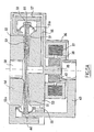
- FIGS. 4A and 4B illustrate an embodiment of the invention in the form of a disc diaphragm pump.
- the body of the pump or pump is in two parts.
- a first part 20 has the general shape of a cup with a bottom 21 and a side skirt 22, the bottom 21 constituting one of the walls rigid of the propulsion chamber.
- This part 20 is provided with two end pieces 23 and 24, the end piece 23 forming the inlet of the circulator and opening out at the periphery of the bottom 21 while the end piece 24 is a delivery end of the circulator, located on the X axis of central symmetry of the portion 20 of the circulator body.
- the portion or cup 20 receives the second portion 25 of the body of the circulator which closes the opening of the skirt 22, this second portion 25 comprising a fixed wall 26 which is placed facing the wall 21 of the first portion 20 to delimit the propellant chamber of the fluid, this part having radial extensions 27 by which it cooperates with the first part 20 inside the skirt 22 to fix the relative position and the spacing of the two walls 21 and 26 surrounding the chamber of propulsion.
- the connection of the two parts 20 and 25 is provided by any known means (clamping, gluing, screwing, welding ).
- Part 25 also has in the axis of symmetry of the circulator, a central column 28 opposite the nozzle 24 which forms the guide element of a moving element described below.
- the propellant chamber 29 contains an elastically deformable membrane 30.
- This membrane 30 which is disc-like has a peripheral flange 31 and a central aperture 32 bounded by an edge 32 a.
- the through holes 32 b are formed in the membrane for distributing the fluid admitted from both sides of this membrane.
- the peripheral bead 31 is the root of two lips 33 and 34 form flexible partial ring whose free edge is equipped with cylindrical bulges 33 a, 34a which sealingly closing the propulsion chamber to the outer periphery of the fixed walls 21 and 26.
- connection of the lip 34 with the part 20 of the circulator body leaves a supply channel 35 permanently communicating the space of the propulsion chamber 29 between the rigid walls 21 and 26 and the interior space of the intake nozzle 23, forming an annular chamber for distributing the intake into the propulsion chamber.
- the second part 25 of the body of the circulator comprises around the column 28 a cylindrical wall 36 which forms the housing of an electromagnetic member having a coil 37 whose axis is the axis of revolution of the circulator and a frame 38 with a gap 39.
- the armature thus defines two poles which are reversed at each of the inversions of the electric current flowing in the winding 37.
- the armature can be made of pure iron or a composite material. base of iron-silicon powder in a resin matrix (known on the market under the brand SOMALLOY) or be constituted by a laminated structure.
- the circulator described finally comprises a stirrup 40 with a central core 41 slidably mounted on the column 28 and equipped at the air gap 39, with a magnetized ring 42 so as to have three superimposed cylindrical polar surfaces denoted NSN in the figures .
- this type of magnetized ring may be of the plastomagnet type, that is to say a finely divided magnetic material (ferrite powder, rare earth - samarium -, iron, cobalt, etc.) in a matrix made of plastic material that has been magnetized during manufacture by controlling the direction of magnetization.
- the magnet can be conceived as an assembly of permanent magnets and appropriate reinforcements.
- the mobile assembly comprises arms 43 which connect it under the skirt 36 to the bead 31 of the membrane 30. These arms are visible at Figure 4B while Figure 4A is a view in orthogonal section to the previous and passing through the axis of revolution of the circulator. It will be noted that the arms 43 enclose the bead 31 by means of a rigid ring 44 visible at the Figure 4A . The arms 43 pass between the lugs 27 of the second portion 25 of the body of the circulator. We will note in Figure 4B that the cutting plane passes through two slots of the skirt 36, slots in which the arms 43 can freely evolve.
- the pump represented at these Figures 4A and 4B is an extremely simple structure. Indeed it has a maximum of eight parts, namely a body in two parts, a membrane, a stirrup, a permanent magnet, a two-part frame as shown in FIG. Figure 4A and a winding. It will also be noted that in this architecture, the most expensive components that are the permanent magnet, the winding and its armature, are of the smallest possible dimensions in order to obtain the lowest cost.
- the other parts are non-magnetic parts and preferably plastic, the membrane being in an elastomer or in a silicone, or in any suitable synthetic material, the cost of which is extremely low.
- the architecture proposed in these figures makes it possible to obtain a very cheap pump or circulator.
- the two parts 53 and 54 of the body of the circulator are such that the lower portion 53 has a supply channel 55 opening into the annular chamber 51 a of the product inlet distribution in the portion 51 of the propulsion chamber, the exhaust of this part 51 of propulsion chamber being connected to a channel 56 also formed here in the body part 53 while the portion 54 of the body of the circulator comprises a channel 57 which comes into communication with the channel 56 to drive the product of the exhausting the chamber portion 51 to the peripheral delivery chamber 52a from the inlet of the chamber portion 52.
- the chamber portion 52 has in the body portion 54 an exhaust port 58.
- the channel 55 is connected to a way not shown to a source of fluid while the orifice 58 has, also not shown, the means of its connection to a pipe for evacuating the fluid under pressure.
- the fluid admitted through the channel 55 in the chamber portion 51 is circulated and undergoes a first pressure rise and then undergoes a second pressure rise in the propulsion chamber portion 52. so for the same flow of fluid occurs a double rise in pressure.
- the AC power supply of the winding 37 leads to reciprocating movement of the stirrup 40 and therefore an alternating excitation of the outer edge 59 of the membrane 50 perpendicularly to its mean plane.
- the number of components of the pump or circulator is very low, resulting in a very cheap cost.
- this embodiment makes it possible to obtain a higher output pressure of the treated fluid than that obtained with the previous embodiment.
- FIG. 5B there is shown an alternative embodiment of the previous figure. Communication between the exhaust portion of the chamber 51 and the chamber part 52 is made by an internal channel in the membrane 50 and referenced 56 a, 56 b and 56 c. There may be several star radial ducts in the thickness of the membrane. It may be advantageous to retain this embodiment in terms of the range of circulators in which, for a dimension, it is sufficient to change the membrane to have a circulator of different characteristics. For an easy realization of this membrane with internal channels, mention will be made of the possibility of producing it in two parts.
- a first disk-shaped portion has a central through hole and the other, also disk-shaped, is superimposed on it and has peripheral orifices through and reliefs on its side facing the first membrane portion, defining with this one of the radial channels connecting the peripheral orifices of the first part (intake) to the central orifice of the second part (exhaust) sandwiched between the two parts joined by any appropriate means.
- the figure 6 illustrates an embodiment of a circulator having two separate stages of propulsion of the fluid treated with two membranes.
- the body 60 of the two-stage circulator comprises three parts 61, 62, 63.
- the portion 61 defines with the portion 62 the walls of a first propulsion chamber 65 whose intake orifice is denoted 66.
- the part 62 has a central exhaust port 67 which terminates under a splitter 64 attached to the portion 62, the splitter 64 forming one of the rigid walls of the second propulsion chamber 68 further defined by the third part 63 of the circulator body.
- the splitter 64 allows by radial channels 69 to conduct the fluid from the exhaust port 67 in a second inlet chamber 70 for the second propulsion chamber 68, which opens into a general exhaust port 71.
- the parts 61, 62, 63 of the circulator body and the distributor 64 are fixed to each other for example by gluing, welding or by any other known means.
- the portion 61 of the circulator comprises, as in the previous examples, a guide column 28 for a motor having the same elements as previously described with the same references.
- the yoke 43 is coupled to two rigid rings 72, 73 superimposed which are respectively connected to the periphery of the membranes 74 and 75.
- the rings 72 and 73 can oscillate parallel to the direction of the geometric axis of revolution of the circulator and they pass through the body of the circulator by means of flexible webs 76 and 77 which isolate from one another the two stages of the circulator.
- FIGS. Figures 4A and 4D an alternative embodiment of the circulator shown in FIGS. Figures 4A and 4D.
- the membrane is devoid of the lips 33 and 34 and the annular distribution chamber 78 of the propulsion chamber is delimited around the periphery of the membrane 30 by a sleeve 79 integral with the periphery of the membrane 30 and the engine crew , sliding along the column 28 and forming a movable inner wall of the annular chamber 78 for distributing the inlet of the propulsion chamber 29.
- This sleeve has on its upper outer surface facing the chamber 78, reliefs 79 a which constitute means for grinding the contents of the chamber 78 because of their reciprocating movement in this chamber.
- the crew motor can also comprise electromagnetic means, consisting of a winding 79 b and a ring permanent magnet 79c, which drives the sleeve, the membrane and the reliefs of a rotary movement about the column 28, increasing thus the efficiency of grinding.
- This rotation which can be continuous, step-by-step, alternative ..., is added to the linear reciprocating movement of the sleeve along the column 28.
- FIG 8 schematically shows an air circulator 80 according to the invention.
- the membrane 81 used in this air circulator is secured by one of its end edges of a pallet 82 which can be driven by a rotary oscillating movement by a motor 83.
- the pallet 82 thus applies a torque of alternative forces on the membrane, which allows to introduce into the membrane an energy almost exclusively of deformation.
- the walls of the circulator 80 here define a circulation chamber whose two sides converge from an intake port 84 of the air to be propelled to an exhaust port 85.
- a means for example magnetostatic (a magnet 87 attracted by a frame 86) for holding the membrane 81 forming the means necessary for the establishment of an extrinsic voltage of the membrane and resistant to its tendency to trussing.
- Such a fan or air blower is very advantageous because it has only very few component parts.
- its flow is important, as experiments have shown, in comparison with its overall size.
- Its performance is advantageous because there is no internal pressure loss related to the change of direction of the air flow.
- the noise generated by this fan is incomparably lower than that found on the fans of the market that are for example hair dryers or hand dryers due in particular to a low frequency of operation.
- a fan membrane assembly comprising a frame 90 in which a membrane 91 is held.
- the membrane is made of an elastic material and the frame is rigid: the membrane is stretched during its installation.
- the membrane is non-elastic and the frame is flexed like an arc whose membrane would be the rope.
- the membrane is inelastic and the frame is rigid: the connection means 92 of the membrane to the frame are elastic.
- the latter flat at rest for example, is inextensible in all or some of the directions of its plane but the membrane remains flexible to be able to bend about an axis of this plane.
- Other embodiments are possible by combining the rigidities and elasticities of the means described in various other ways.
- FIG. 11 An example of application of a fan according to the invention is illustrated by the figure 11 .
- This figure represents an electronic component 100, one of whose faces is in a known manner, provided with a radiator for dissipating the heat produced during its operation.
- This radiator is, according to the invention, shaped in a tunnel with two flanges 101 and 102.
- This tunnel constitutes the body of a fan according to the invention, in which is housed a membrane 91 as shown in FIG. figure 9 , and motorized with a motor of the kind represented in figure 10 .
- the surfaces of the radiator facing the membrane will preferably be grooved to increase the exchange surfaces between the radiator and the air propelled by the circulator.
- the entire body of the air circulator can achieve this radiator function, architecture that leads to a very compact fan and especially ultra-flat.
- an exciter 97 for example a piezoelectric or electromechanical vibrator, capable of creating in the body of the circulator a vibration of adjustable amplitude and phase opposite to the reciprocating movement of the moving element consisting of the stirrup 43, the permanent magnet and the membrane 30. Thanks to this vibration member, we can achieve active sound insulation that makes the circulator quiet. This arrangement opens the field of circulator applications to all areas in which noise is an important factor. Of particular note are domestic aquarium pumps.
Landscapes
- Engineering & Computer Science (AREA)
- Mechanical Engineering (AREA)
- General Engineering & Computer Science (AREA)
- Reciprocating Pumps (AREA)
Claims (14)
- Membranzirkulator für ein zum Fließen geeignetes Material, umfassend ein Zirkulatorgehäuse, in dem ein innerer Kreis ausgebildet ist, der mindestens eine Einlassöffnung (2a) für das Material, eine Antriebskammer und mindestens eine Auslassöffnung (4a) für dieses Material hat, wobei die Antriebskammer starre Wände (9; 10) hat, zwischen denen eine verformbare Membran (1) mit einem Rand (2) nahe der Einlassöffnung (2a) und einem Rand (4) nahe der Auslassöffnung (4a) angeordnet ist, wobei die Membran den Träger für eine Welle bildet, während ein Organ für eine mechanische wechselnde Erregung der Membran mit der Membran auf der Seite der Einlassöffnung (2a) gekoppelt ist, um auf den entsprechenden Rand der Membran eine mechanische Energie zu übertragen, die die genannte Welle erzeugt, dadurch gekennzeichnet, dass die starren Wände (9; 10) des Zirkulators im Inneren von Umhüllungsflächen (7; 8) zur Umhüllung der freien Amplitude der Welle angeordnet sind, die sich entlang der Membran (1) ausbreitet, und dass die Membran (1) über mindestens einen ihrer Ränder mit Mitteln verbunden ist, die die Erzeugung einer Spannung (6a; 6b) in der Membran zumindest während der Erzeugung der Welle zur Folge haben, derart, dass im Betrieb diese in der Membran herrschende Spannung zwischen einem oberen Wert (6b) auf der Seite der Auslassöffnung (4a) und einem unteren Wert (6a) auf der Seite der Einlassöffnung (2a) variabel ist.
- Zirkulator nach Anspruch 1, dadurch gekennzeichnet, dass ein erster Abschnitt (51) der Antriebskammer, der von dem Gehäuse (53) des Zirkulators und einer der Seiten der Membran (50) begrenzt ist, mit einer Einlassöffnung für eine externe Versorgung mit zu behandelndem Material und mit einer Auslassöffnung verbunden ist, die selbst mit einer Einlassöffnung eines zweiten Abschnitts (52) der Antriebskammer verbunden ist, der von dem Gehäuse (54) des Zirkulators und der anderen Seite der Membran (50) begrenzt ist, wobei dieser andere Abschnitt in die Auslassöffnung (58) des Zirkulators mündet, wobei die beiden Kammerabschnitte (51; 52) ferner zueinander isoliert sind.
- Zirkulator nach Anspruch 2, dadurch gekennzeichnet, dass die Verbindung zwischen dem Auslass des ersten Abschnitts (51) und dem Einlass des zweiten Abschnitts (52) durch im Inneren des Gehäuses (53; 54) des Zirkulators ausgebildete Kanäle (56) sichergestellt ist.
- Zirkulator nach Anspruch 2, dadurch gekennzeichnet, dass die Verbindung zwischen dem Auslass des ersten Abschnitts (51) und dem Einlass des zweiten Abschnitts (52) durch im Inneren der Membran (50) des Zirkulators ausgebildete Kanäle (56a; 56b; 56c) sichergestellt ist.
- Zirkulator nach einem der vorhergehenden Ansprüche, dadurch gekennzeichnet, dass er eine diskoidale Membran (30) umfasst, deren Außenumfang an einer beweglichen Einrichtung (40) zur linearen mechanischen wechselnden Erregung gekoppelt ist, die entlang einer Achse, die senkrecht zur Ebene der Membran ist, mittels einer zentralen Führungssäule (28) geführt ist, die fest mit dem Gehäuse des Zirkulators verbunden ist.
- Zirkulator nach Anspruch 5, dadurch gekennzeichnet, dass die bewegliche Einrichtung (40) einen ringförmigen Dauermagneten (42) um die Führungssäule (28) herum umfasst, der einen Tauchkern für eine Magnetspule (37) in einem festen Anker (38) bildet, der um den Dauermagnet (42) herum angeordnet ist.
- Zirkulator nach einem der vorhergehenden Ansprüche, dadurch gekennzeichnet, dass das Gehäuse des Zirkulators mehrere übereinander angeordnete Antriebsräume (65, 68) aufweist, die zwischen einer Einlassöffnung (66) und einer Auslassöffnung (71) in Reihe verbunden sind, wobei die Membranen (74, 75) jedes Raums über ihren Außenrand an eine einzige bewegliche Einrichtung (40) gekoppelt sind.
- Zirkulator nach einem der vorhergehenden Ansprüche, dadurch gekennzeichnet, dass die bewegliche Einrichtung eine Hülse (79) um die Membran (30) herum umfasst, die Erhebungen (79a) zum Zerkleinern des zu behandelnden Produkts umfasst, das sich in dem Zirkulationsraum nahe der Einlassöffnung befindet.
- Zirkulator nach einem der vorhergehenden Ansprüche, dadurch gekennzeichnet, dass er einen Schwingungserzeuger (97) umfasst, um in dem Gehäuse des Zirkulators eine Schwingung mit einer Phase zu erzeugen, die der der Wechselbewegung der beweglichen Einrichtung (40) entgegengesetzt ist.
- Zirkulator nach Anspruch 1, wobei die Membran (81) eine Lamelle in Form eines Vierecks ist, mit zwei gegenüberliegenden parallelen Seiten, dadurch gekennzeichnet, dass der Generator für die Verformungen ein Generator (82; 93; 94; 95) zur Erzeugung eines Wechselkräftepaares ist.
- Zirkulator nach Anspruch 10, dadurch gekennzeichnet, dass der Rand der Membran (91) nahe dem Generator (82; 93, 94; 95) für Verformungen und derjenige, der diesem letztgenannten gegenüberliegt, an ein Gestell (90) in Form eines Rahmens gekoppelt sind, das mit der Membran (91) zusammenwirkt, um die für die Ausbreitung der Wellen erforderliche Spannung sicherzustellen.
- Zirkulator nach einem der Ansprüche 10 bis 11, dadurch gekennzeichnet, dass die Membran eine trapezförmige Kontur hat.
- Zirkulator nach einem der Ansprüche 10 bis 12, dadurch gekennzeichnet, dass mindestens eine der Wände des Gehäuses (101), die die Antriebskammer begrenzt, eine Wärmetauschwand bildet, die eine von dem zirkulierenden Material überspülte Austauschfläche aufweist.
- Zirkulator nach einem der vorhergehenden Ansprüche, dadurch gekennzeichnet, dass das Gehäuse fest mit einem anzutreibenden Gerät in einer Umgebung verbunden ist, von der ein Teil das oben genannte zum Fließen geeignete Material darstellt, das die Antriebskammer des Zirkulators durchfließt.
Priority Applications (1)
| Application Number | Priority Date | Filing Date | Title |
|---|---|---|---|
| PL06831180T PL1969232T3 (pl) | 2005-11-30 | 2006-11-28 | Cyrkulator z membraną |
Applications Claiming Priority (2)
| Application Number | Priority Date | Filing Date | Title |
|---|---|---|---|
| FR0512182A FR2893991B1 (fr) | 2005-11-30 | 2005-11-30 | Circulateur a membrane |
| PCT/FR2006/002596 WO2007063206A1 (fr) | 2005-11-30 | 2006-11-28 | Circulateur a membrane |
Publications (2)
| Publication Number | Publication Date |
|---|---|
| EP1969232A1 EP1969232A1 (de) | 2008-09-17 |
| EP1969232B1 true EP1969232B1 (de) | 2016-01-27 |
Family
ID=36763055
Family Applications (1)
| Application Number | Title | Priority Date | Filing Date |
|---|---|---|---|
| EP06831180.2A Active EP1969232B1 (de) | 2005-11-30 | 2006-11-28 | Membranzirkulator |
Country Status (7)
| Country | Link |
|---|---|
| EP (1) | EP1969232B1 (de) |
| JP (1) | JP5335433B2 (de) |
| DK (1) | DK1969232T3 (de) |
| ES (1) | ES2569358T3 (de) |
| FR (1) | FR2893991B1 (de) |
| PL (1) | PL1969232T3 (de) |
| WO (1) | WO2007063206A1 (de) |
Cited By (1)
| Publication number | Priority date | Publication date | Assignee | Title |
|---|---|---|---|---|
| CN114450221A (zh) * | 2019-08-09 | 2022-05-06 | Finx公司 | 用于移动船舶的设备 |
Families Citing this family (14)
| Publication number | Priority date | Publication date | Assignee | Title |
|---|---|---|---|---|
| FR2918128B1 (fr) * | 2007-06-27 | 2017-06-09 | Valeo Systemes Thermiques Branche Thermique Moteur | Pompe de circulation de fluide a court-circuit integre. |
| FR2934651B1 (fr) * | 2008-08-01 | 2010-08-27 | Ams R & D Sas | Pompe a membrane ondulante perfectionnee. |
| FR2934652B1 (fr) * | 2008-08-01 | 2013-01-11 | Ams R & D Sas | Pompe a membrane ondulante de rendement ameliore. |
| FR2934650B1 (fr) * | 2008-08-01 | 2010-09-17 | Jean Baptiste Drevet | Generateur d'energie. |
| FR2972772B1 (fr) * | 2011-03-14 | 2015-12-18 | Jean Baptiste Drevet | Generateur hydrolien |
| FR3032917B1 (fr) * | 2015-02-20 | 2017-02-17 | Valeo Systemes Thermiques | Module de conditionnement d'air d'un habitacle de vehicule automobile |
| FR3032914B1 (fr) * | 2015-02-20 | 2017-02-17 | Valeo Systemes Thermiques | Installation de conditionnement thermique d'un habitacle de vehicule automobile |
| FR3032915B1 (fr) * | 2015-02-20 | 2017-02-17 | Valeo Systemes Thermiques | Installation de conditionnement thermique d'un habitacle de vehicule automobile |
| FR3035708B1 (fr) * | 2015-04-30 | 2019-07-12 | Valeo Systemes Thermiques | Pulseur d'air pour vehicule automobile |
| US9968720B2 (en) * | 2016-04-11 | 2018-05-15 | CorWave SA | Implantable pump system having an undulating membrane |
| FR3074544B1 (fr) | 2017-12-05 | 2021-10-22 | Ams R&D Sas | Circulateur a membrane ondulante pilotee |
| FR3142513A1 (fr) * | 2022-11-25 | 2024-05-31 | Finx | système d’accroche de membrane pour dispositif generateur de flux fluidique |
| FR3144231A1 (fr) * | 2022-12-23 | 2024-06-28 | Finx | Propulseur hydraulique comprenant une carte électronique immérgée |
| FR3144105A1 (fr) * | 2022-12-23 | 2024-06-28 | Finx | système de mise en tension d’une membrane équipant un dispositif de générateur de flux fluidique |
Family Cites Families (7)
| Publication number | Priority date | Publication date | Assignee | Title |
|---|---|---|---|---|
| US2888877A (en) * | 1956-04-19 | 1959-06-02 | Ohio Commw Eng Co | Apparatus for pumping |
| WO1980002445A1 (en) * | 1979-05-07 | 1980-11-13 | Rotron Inc | Solid state blower |
| JPH02144680U (de) * | 1989-05-08 | 1990-12-07 | ||
| FR2650862B1 (fr) * | 1989-08-11 | 1991-11-08 | Salmson Pompes | Dispositif de propulsion d'un fluide |
| FR2744769B1 (fr) * | 1996-02-12 | 1999-02-12 | Drevet Jean Baptiste | Circulateur de fluide a membrane vibrante |
| JP2002031188A (ja) * | 2000-07-17 | 2002-01-31 | Osaka Gas Co Ltd | アクティブ防振装置 |
| WO2005119062A1 (fr) * | 2004-05-26 | 2005-12-15 | Viacor | Circulateur de fluide a membrane rigide |
-
2005
- 2005-11-30 FR FR0512182A patent/FR2893991B1/fr not_active Expired - Fee Related
-
2006
- 2006-11-28 EP EP06831180.2A patent/EP1969232B1/de active Active
- 2006-11-28 DK DK06831180.2T patent/DK1969232T3/en active
- 2006-11-28 ES ES06831180.2T patent/ES2569358T3/es active Active
- 2006-11-28 PL PL06831180T patent/PL1969232T3/pl unknown
- 2006-11-28 JP JP2008542792A patent/JP5335433B2/ja active Active
- 2006-11-28 WO PCT/FR2006/002596 patent/WO2007063206A1/fr not_active Ceased
Cited By (1)
| Publication number | Priority date | Publication date | Assignee | Title |
|---|---|---|---|---|
| CN114450221A (zh) * | 2019-08-09 | 2022-05-06 | Finx公司 | 用于移动船舶的设备 |
Also Published As
| Publication number | Publication date |
|---|---|
| PL1969232T3 (pl) | 2016-08-31 |
| JP2009517594A (ja) | 2009-04-30 |
| EP1969232A1 (de) | 2008-09-17 |
| ES2569358T3 (es) | 2016-05-10 |
| FR2893991A1 (fr) | 2007-06-01 |
| WO2007063206A1 (fr) | 2007-06-07 |
| JP5335433B2 (ja) | 2013-11-06 |
| FR2893991B1 (fr) | 2013-10-11 |
| DK1969232T3 (en) | 2016-05-02 |
Similar Documents
| Publication | Publication Date | Title |
|---|---|---|
| EP1969232B1 (de) | Membranzirkulator | |
| US9080564B2 (en) | Diaphragm circulator | |
| EP0880650B1 (de) | Vibrierende membranpumpe | |
| EP3707381B1 (de) | Flüssigkeitszirkulator mit welliger membran | |
| EP0412856B1 (de) | Vorrichtung zur Förderung einer Flüssigkeit | |
| EP1040274B1 (de) | Verdrängungspumpe | |
| FR2685937A1 (fr) | Pompe a carburant a ailettes de turbine et a moteur electrique. | |
| CA2687070A1 (fr) | Actionneur electromagnetique a reluctance variable | |
| EP4364281A1 (de) | Elektromagnetische linearbewegungsmaschine mit mit magnetischen elementen verbundenen stangen | |
| FR3137658A1 (fr) | Dispositif générateur de flux fluidique à membrane multi-directionnel | |
| FR3124659A1 (fr) | Machine electromagnetique a mouvement lineaire comprenant des tiges magnetiques | |
| WO2024200306A1 (fr) | Déflecteur mobile pour dispositif générateur de flux fluidique à membrane | |
| WO2026047293A1 (fr) | Haut-parleur pulsant pneumatique pour véhicule automobile | |
| FR2861909A1 (fr) | Dispositif de stockage d'energie a volant d'inertie. | |
| CA3223717A1 (fr) | Dispositif generateur de flux fluidique | |
| FR2808916A1 (fr) | Source et systeme electroaeroacoustiques pour controle actif du bruit | |
| EP2534851B1 (de) | Magnetischer elektrodynamischer wandlermotor | |
| FR2930679A1 (fr) | Dispositif de generation de flux thermique a materiau magnetocalorique |
Legal Events
| Date | Code | Title | Description |
|---|---|---|---|
| PUAI | Public reference made under article 153(3) epc to a published international application that has entered the european phase |
Free format text: ORIGINAL CODE: 0009012 |
|
| 17P | Request for examination filed |
Effective date: 20080630 |
|
| AK | Designated contracting states |
Kind code of ref document: A1 Designated state(s): AT BE BG CH CY CZ DE DK EE ES FI FR GB GR HU IE IS IT LI LT LU LV MC NL PL PT RO SE SI SK TR |
|
| RAP1 | Party data changed (applicant data changed or rights of an application transferred) |
Owner name: SAM AMSTAR |
|
| RIN1 | Information on inventor provided before grant (corrected) |
Inventor name: JEAN-BAPTISTE DREVET |
|
| RAP1 | Party data changed (applicant data changed or rights of an application transferred) |
Owner name: AMS R&D SAS |
|
| DAX | Request for extension of the european patent (deleted) | ||
| 17Q | First examination report despatched |
Effective date: 20140701 |
|
| REG | Reference to a national code |
Ref country code: DE Ref legal event code: R079 Ref document number: 602006047841 Country of ref document: DE Free format text: PREVIOUS MAIN CLASS: F04B0043000000 Ipc: F04B0043040000 |
|
| GRAP | Despatch of communication of intention to grant a patent |
Free format text: ORIGINAL CODE: EPIDOSNIGR1 |
|
| RIC1 | Information provided on ipc code assigned before grant |
Ipc: F04B 43/00 20060101ALI20150623BHEP Ipc: F04B 43/04 20060101AFI20150623BHEP |
|
| INTG | Intention to grant announced |
Effective date: 20150730 |
|
| GRAS | Grant fee paid |
Free format text: ORIGINAL CODE: EPIDOSNIGR3 |
|
| GRAA | (expected) grant |
Free format text: ORIGINAL CODE: 0009210 |
|
| AK | Designated contracting states |
Kind code of ref document: B1 Designated state(s): AT BE BG CH CY CZ DE DK EE ES FI FR GB GR HU IE IS IT LI LT LU LV MC NL PL PT RO SE SI SK TR |
|
| REG | Reference to a national code |
Ref country code: GB Ref legal event code: FG4D Free format text: NOT ENGLISH |
|
| REG | Reference to a national code |
Ref country code: CH Ref legal event code: EP |
|
| REG | Reference to a national code |
Ref country code: AT Ref legal event code: REF Ref document number: 772850 Country of ref document: AT Kind code of ref document: T Effective date: 20160215 |
|
| REG | Reference to a national code |
Ref country code: IE Ref legal event code: FG4D Free format text: LANGUAGE OF EP DOCUMENT: FRENCH |
|
| REG | Reference to a national code |
Ref country code: DE Ref legal event code: R096 Ref document number: 602006047841 Country of ref document: DE |
|
| REG | Reference to a national code |
Ref country code: CH Ref legal event code: NV Representative=s name: BOVARD AG, CH |
|
| REG | Reference to a national code |
Ref country code: DK Ref legal event code: T3 Effective date: 20160425 |
|
| REG | Reference to a national code |
Ref country code: ES Ref legal event code: FG2A Ref document number: 2569358 Country of ref document: ES Kind code of ref document: T3 Effective date: 20160510 |
|
| REG | Reference to a national code |
Ref country code: SE Ref legal event code: TRGR |
|
| REG | Reference to a national code |
Ref country code: NL Ref legal event code: FP |
|
| REG | Reference to a national code |
Ref country code: LT Ref legal event code: MG4D |
|
| REG | Reference to a national code |
Ref country code: AT Ref legal event code: MK05 Ref document number: 772850 Country of ref document: AT Kind code of ref document: T Effective date: 20160127 |
|
| PG25 | Lapsed in a contracting state [announced via postgrant information from national office to epo] |
Ref country code: FI Free format text: LAPSE BECAUSE OF FAILURE TO SUBMIT A TRANSLATION OF THE DESCRIPTION OR TO PAY THE FEE WITHIN THE PRESCRIBED TIME-LIMIT Effective date: 20160127 Ref country code: GR Free format text: LAPSE BECAUSE OF FAILURE TO SUBMIT A TRANSLATION OF THE DESCRIPTION OR TO PAY THE FEE WITHIN THE PRESCRIBED TIME-LIMIT Effective date: 20160428 |
|
| PG25 | Lapsed in a contracting state [announced via postgrant information from national office to epo] |
Ref country code: LV Free format text: LAPSE BECAUSE OF FAILURE TO SUBMIT A TRANSLATION OF THE DESCRIPTION OR TO PAY THE FEE WITHIN THE PRESCRIBED TIME-LIMIT Effective date: 20160127 Ref country code: AT Free format text: LAPSE BECAUSE OF FAILURE TO SUBMIT A TRANSLATION OF THE DESCRIPTION OR TO PAY THE FEE WITHIN THE PRESCRIBED TIME-LIMIT Effective date: 20160127 Ref country code: PT Free format text: LAPSE BECAUSE OF FAILURE TO SUBMIT A TRANSLATION OF THE DESCRIPTION OR TO PAY THE FEE WITHIN THE PRESCRIBED TIME-LIMIT Effective date: 20160527 Ref country code: IS Free format text: LAPSE BECAUSE OF FAILURE TO SUBMIT A TRANSLATION OF THE DESCRIPTION OR TO PAY THE FEE WITHIN THE PRESCRIBED TIME-LIMIT Effective date: 20160527 Ref country code: LT Free format text: LAPSE BECAUSE OF FAILURE TO SUBMIT A TRANSLATION OF THE DESCRIPTION OR TO PAY THE FEE WITHIN THE PRESCRIBED TIME-LIMIT Effective date: 20160127 |
|
| REG | Reference to a national code |
Ref country code: DE Ref legal event code: R097 Ref document number: 602006047841 Country of ref document: DE |
|
| PG25 | Lapsed in a contracting state [announced via postgrant information from national office to epo] |
Ref country code: EE Free format text: LAPSE BECAUSE OF FAILURE TO SUBMIT A TRANSLATION OF THE DESCRIPTION OR TO PAY THE FEE WITHIN THE PRESCRIBED TIME-LIMIT Effective date: 20160127 |
|
| REG | Reference to a national code |
Ref country code: FR Ref legal event code: PLFP Year of fee payment: 11 |
|
| PG25 | Lapsed in a contracting state [announced via postgrant information from national office to epo] |
Ref country code: CZ Free format text: LAPSE BECAUSE OF FAILURE TO SUBMIT A TRANSLATION OF THE DESCRIPTION OR TO PAY THE FEE WITHIN THE PRESCRIBED TIME-LIMIT Effective date: 20160127 Ref country code: RO Free format text: LAPSE BECAUSE OF FAILURE TO SUBMIT A TRANSLATION OF THE DESCRIPTION OR TO PAY THE FEE WITHIN THE PRESCRIBED TIME-LIMIT Effective date: 20160127 Ref country code: SK Free format text: LAPSE BECAUSE OF FAILURE TO SUBMIT A TRANSLATION OF THE DESCRIPTION OR TO PAY THE FEE WITHIN THE PRESCRIBED TIME-LIMIT Effective date: 20160127 |
|
| PLBE | No opposition filed within time limit |
Free format text: ORIGINAL CODE: 0009261 |
|
| STAA | Information on the status of an ep patent application or granted ep patent |
Free format text: STATUS: NO OPPOSITION FILED WITHIN TIME LIMIT |
|
| 26N | No opposition filed |
Effective date: 20161028 |
|
| PG25 | Lapsed in a contracting state [announced via postgrant information from national office to epo] |
Ref country code: BG Free format text: LAPSE BECAUSE OF FAILURE TO SUBMIT A TRANSLATION OF THE DESCRIPTION OR TO PAY THE FEE WITHIN THE PRESCRIBED TIME-LIMIT Effective date: 20160427 Ref country code: SI Free format text: LAPSE BECAUSE OF FAILURE TO SUBMIT A TRANSLATION OF THE DESCRIPTION OR TO PAY THE FEE WITHIN THE PRESCRIBED TIME-LIMIT Effective date: 20160127 |
|
| REG | Reference to a national code |
Ref country code: IE Ref legal event code: MM4A |
|
| PG25 | Lapsed in a contracting state [announced via postgrant information from national office to epo] |
Ref country code: LU Free format text: LAPSE BECAUSE OF NON-PAYMENT OF DUE FEES Effective date: 20161130 |
|
| REG | Reference to a national code |
Ref country code: FR Ref legal event code: PLFP Year of fee payment: 12 |
|
| PG25 | Lapsed in a contracting state [announced via postgrant information from national office to epo] |
Ref country code: IE Free format text: LAPSE BECAUSE OF NON-PAYMENT OF DUE FEES Effective date: 20161128 |
|
| PG25 | Lapsed in a contracting state [announced via postgrant information from national office to epo] |
Ref country code: HU Free format text: LAPSE BECAUSE OF FAILURE TO SUBMIT A TRANSLATION OF THE DESCRIPTION OR TO PAY THE FEE WITHIN THE PRESCRIBED TIME-LIMIT; INVALID AB INITIO Effective date: 20061128 Ref country code: CY Free format text: LAPSE BECAUSE OF FAILURE TO SUBMIT A TRANSLATION OF THE DESCRIPTION OR TO PAY THE FEE WITHIN THE PRESCRIBED TIME-LIMIT Effective date: 20160127 |
|
| PG25 | Lapsed in a contracting state [announced via postgrant information from national office to epo] |
Ref country code: MC Free format text: LAPSE BECAUSE OF FAILURE TO SUBMIT A TRANSLATION OF THE DESCRIPTION OR TO PAY THE FEE WITHIN THE PRESCRIBED TIME-LIMIT Effective date: 20160127 Ref country code: TR Free format text: LAPSE BECAUSE OF FAILURE TO SUBMIT A TRANSLATION OF THE DESCRIPTION OR TO PAY THE FEE WITHIN THE PRESCRIBED TIME-LIMIT Effective date: 20160127 |
|
| PGFP | Annual fee paid to national office [announced via postgrant information from national office to epo] |
Ref country code: NL Payment date: 20231120 Year of fee payment: 18 |
|
| PGFP | Annual fee paid to national office [announced via postgrant information from national office to epo] |
Ref country code: GB Payment date: 20231123 Year of fee payment: 18 |
|
| PGFP | Annual fee paid to national office [announced via postgrant information from national office to epo] |
Ref country code: SE Payment date: 20231120 Year of fee payment: 18 Ref country code: IT Payment date: 20231124 Year of fee payment: 18 Ref country code: FR Payment date: 20231120 Year of fee payment: 18 Ref country code: DK Payment date: 20231124 Year of fee payment: 18 Ref country code: DE Payment date: 20231121 Year of fee payment: 18 Ref country code: CH Payment date: 20231202 Year of fee payment: 18 |
|
| PGFP | Annual fee paid to national office [announced via postgrant information from national office to epo] |
Ref country code: PL Payment date: 20231116 Year of fee payment: 18 Ref country code: BE Payment date: 20231120 Year of fee payment: 18 |
|
| PGFP | Annual fee paid to national office [announced via postgrant information from national office to epo] |
Ref country code: ES Payment date: 20240126 Year of fee payment: 18 |
|
| REG | Reference to a national code |
Ref country code: DE Ref legal event code: R119 Ref document number: 602006047841 Country of ref document: DE |
|
| REG | Reference to a national code |
Ref country code: DK Ref legal event code: EBP Effective date: 20241130 |
|
| REG | Reference to a national code |
Ref country code: CH Ref legal event code: PL |
|
| REG | Reference to a national code |
Ref country code: SE Ref legal event code: EUG |
|
| REG | Reference to a national code |
Ref country code: NL Ref legal event code: MM Effective date: 20241201 |
|
| REG | Reference to a national code |
Ref country code: CH Ref legal event code: PL |
|
| GBPC | Gb: european patent ceased through non-payment of renewal fee |
Effective date: 20241128 |
|
| PG25 | Lapsed in a contracting state [announced via postgrant information from national office to epo] |
Ref country code: CH Free format text: LAPSE BECAUSE OF NON-PAYMENT OF DUE FEES Effective date: 20241130 |
|
| PG25 | Lapsed in a contracting state [announced via postgrant information from national office to epo] |
Ref country code: NL Free format text: LAPSE BECAUSE OF NON-PAYMENT OF DUE FEES Effective date: 20241201 |
|
| REG | Reference to a national code |
Ref country code: BE Ref legal event code: MM Effective date: 20241130 |
|
| PG25 | Lapsed in a contracting state [announced via postgrant information from national office to epo] |
Ref country code: DK Free format text: LAPSE BECAUSE OF NON-PAYMENT OF DUE FEES Effective date: 20241130 Ref country code: DE Free format text: LAPSE BECAUSE OF NON-PAYMENT OF DUE FEES Effective date: 20250603 |
|
| PG25 | Lapsed in a contracting state [announced via postgrant information from national office to epo] |
Ref country code: SE Free format text: LAPSE BECAUSE OF NON-PAYMENT OF DUE FEES Effective date: 20241129 Ref country code: IT Free format text: LAPSE BECAUSE OF NON-PAYMENT OF DUE FEES Effective date: 20241128 |
|
| PG25 | Lapsed in a contracting state [announced via postgrant information from national office to epo] |
Ref country code: BE Free format text: LAPSE BECAUSE OF NON-PAYMENT OF DUE FEES Effective date: 20241130 Ref country code: GB Free format text: LAPSE BECAUSE OF NON-PAYMENT OF DUE FEES Effective date: 20241128 |
|
| PG25 | Lapsed in a contracting state [announced via postgrant information from national office to epo] |
Ref country code: FR Free format text: LAPSE BECAUSE OF NON-PAYMENT OF DUE FEES Effective date: 20241130 |
|
| REG | Reference to a national code |
Ref country code: ES Ref legal event code: FD2A Effective date: 20260105 |
|
| PG25 | Lapsed in a contracting state [announced via postgrant information from national office to epo] |
Ref country code: ES Free format text: LAPSE BECAUSE OF NON-PAYMENT OF DUE FEES Effective date: 20241129 |