EP3706933B1 - Strangführungssegment und stranggiessanlage - Google Patents
Strangführungssegment und stranggiessanlage Download PDFInfo
- Publication number
- EP3706933B1 EP3706933B1 EP18782390.1A EP18782390A EP3706933B1 EP 3706933 B1 EP3706933 B1 EP 3706933B1 EP 18782390 A EP18782390 A EP 18782390A EP 3706933 B1 EP3706933 B1 EP 3706933B1
- Authority
- EP
- European Patent Office
- Prior art keywords
- guide segment
- hydraulic cylinder
- upper frame
- strand guide
- strip guide
- Prior art date
- Legal status (The legal status is an assumption and is not a legal conclusion. Google has not performed a legal analysis and makes no representation as to the accuracy of the status listed.)
- Active
Links
Images

Classifications
-
- B—PERFORMING OPERATIONS; TRANSPORTING
- B22—CASTING; POWDER METALLURGY
- B22D—CASTING OF METALS; CASTING OF OTHER SUBSTANCES BY THE SAME PROCESSES OR DEVICES
- B22D11/00—Continuous casting of metals, i.e. casting in indefinite lengths
- B22D11/12—Accessories for subsequent treating or working cast stock in situ
- B22D11/128—Accessories for subsequent treating or working cast stock in situ for removing
-
- B—PERFORMING OPERATIONS; TRANSPORTING
- B22—CASTING; POWDER METALLURGY
- B22D—CASTING OF METALS; CASTING OF OTHER SUBSTANCES BY THE SAME PROCESSES OR DEVICES
- B22D11/00—Continuous casting of metals, i.e. casting in indefinite lengths
- B22D11/12—Accessories for subsequent treating or working cast stock in situ
- B22D11/1206—Accessories for subsequent treating or working cast stock in situ for plastic shaping of strands
-
- B—PERFORMING OPERATIONS; TRANSPORTING
- B22—CASTING; POWDER METALLURGY
- B22D—CASTING OF METALS; CASTING OF OTHER SUBSTANCES BY THE SAME PROCESSES OR DEVICES
- B22D11/00—Continuous casting of metals, i.e. casting in indefinite lengths
- B22D11/16—Controlling or regulating processes or operations
- B22D11/20—Controlling or regulating processes or operations for removing cast stock
Definitions
- the present invention relates to a strand guide segment for a continuous caster according to the preamble of independent claim 1.
- the invention also relates to a continuous caster according to claim 10.
- the liquid metal is first introduced into a mold and then guided as a strand in partially solidified form through a strand guide, also called a support roller frame, with rollers.
- a strand guide also called a support roller frame
- each strand guide segment having an upper frame and a lower frame opposite this, which carry strand-guiding rollers and the distance between them can be adjusted to the casting format via tie rods and spacers.
- the upper frame and the lower frame of a respective strand guide segment are clamped against one another by four hydraulic cylinder units which are arranged at the outer corners outside the strand path and connect the upper frame and the lower frame to one another.
- a strand guide with strand guide segments is known in which the respective upper frame and lower frame are connected to one another via hydraulic cylinder units and can be adjusted against one another in a controlled manner.
- the hydraulic cylinder units are mounted to be journalled on the upper frame and the lower frame.
- the upper frame and the lower frame For maintenance purposes on such strand guide segments, the upper frame and the lower frame must be separated or decoupled from one another. For this purpose, the respective bearings of the hydraulic cylinder units on the upper frame or the lower frame must be opened. So that such a storage can be opened easily, a sufficiently large clearance must be provided for it.
- a sufficiently large clearance must be provided for it.
- such a realization has a disadvantageous effect on the accuracy of the strand thickness set by the strand guide segment. Large deviations can therefore occur between the strand thickness actually set by the strand guide segment and the desired strand thickness.
- a strand guide segment with two hydraulic cylinder units for setting a distance between the upper frame and the lower frame is known, the hydraulic cylinder units being detachably connected to the upper frame by means of a flange device.
- the frames are connected to one another by a separate hydraulic clamping device.
- the EP0 030 223 A2 discloses a support and guide frame for a continuous caster, with an upper supporting structure which is releasably attached to the lower supporting structure by means of a pressure medium cylinder attached to it via a tie rod and a strut.
- the present invention is therefore based on the object of providing an alternative strand guide segment for a continuous caster which ensures simple maintenance and at the same time great accuracy of the strand thickness set by the strand guide segment.
- the present invention is intended to provide a continuous caster which can be easily maintained and ensures a high level of accuracy of the strand thickness each set by its strand guide segments.
- the strand guide segment presented for a continuous caster for metals, in particular steel materials has an upper frame and a lower frame, which during a casting operation of the continuous caster position-controlled hydraulic cylinder units are connected to one another.
- the Hydraulic cylinder units are arranged and designed to set a distance between the upper frame and the lower frame, the set distance specifying or setting a strand thickness of a strand to be guided through the strand guide segment.
- Each hydraulic cylinder unit has a piston rod which can be extended or retracted in a position-controlled manner by means of an applied hydraulic pressure in order to increase or decrease the distance between the upper frame and the lower frame.
- the strand guide segment presented preferably has two pairs of hydraulic cylinder units which are arranged on both sides and outside the strand path of the strand guide segment.
- the strand guide segment preferably has a side frame on both sides of the strand path, which allow a guided movement of the upper frame and the lower frame relative to one another in response to deflections or changes in length of the hydraulic cylinder units.
- a first end of each of the hydraulic cylinder units is supported on the upper frame.
- each of the hydraulic cylinder units, specifically its piston rod is detachably connected to a respective pull rod at its second end facing away from the upper frame by means of a respective flange device.
- the tie rods are mounted on the subframe at their end facing away from the flange device.
- Each hydraulic cylinder unit is preferably rigidly connected to the respective pull rod by means of the respective flange device.
- Changes in length of the hydraulic cylinder units mounted on the upper frame, brought about by position control, are converted into a corresponding change in the distance between the upper frame and the lower frame via the tie rods mounted on the lower frame.
- the tie rods are preferably designed so that they cannot be changed in length.
- the provision of the flange devices, via which a respective hydraulic cylinder unit or its piston rod is detachably connected to a respective pull rod, enables simple separation of the upper frame and Lower frame without having to open the bearings of the hydraulic cylinder units on the upper frame.
- the bearings of the hydraulic cylinder units do not need to be provided with a large amount of play.
- the bearings can therefore be designed with little play, so that the strand guide segment presented ensures a high level of precision for the strand thickness set.
- the hydraulic cylinder units in particular their piston rods, are screwed to the respective tie rods via the respective flange devices.
- the screw connections enable the hydraulic cylinder devices to be easily loosened from the tie rods, equivalent to a simple separation of the upper frame from the lower frame, during maintenance and, at the same time, a very high tensile strength connection between the hydraulic cylinder devices and the tie rods during the casting operation.
- the tie rods are releasably connected to their respective flange device.
- the hydraulic cylinder units are releasably connected to the respective flange device. If a respective flange connection is detachably connected both to the respective tie rod and to the respective hydraulic cylinder unit, the flange connection can be removed particularly easily during maintenance work and checked for wear. It can also be provided that the respective flange device is thermally shrunk onto the respective hydraulic cylinder unit, in particular on its piston rod, and this flange device is screwed to the respective pull rod.
- the flange device is firmly connected to one of the group consisting of the hydraulic cylinder unit and the pull rod, and the flange device to the other of the Group of the hydraulic cylinder unit and the pull rod releasably connected, in particular screwed, is.
- the hydraulic cylinder units are mounted on bolts on the upper frame by means of pivot bearings.
- the hydraulic cylinder units are supported with particularly little play, so that the strand guide segment presented ensures a high level of precision in the set strand thickness due to the low-play connection of the upper frame to the lower frame.
- the tie rods are mounted on bolts on the subframe by means of pivot bearings.
- the tie rods are supported with particularly little play, so that the strand guide segment presented ensures a high level of precision in the set strand thickness due to the low-play connection of the lower frame to the upper frame.
- Both the hydraulic cylinder units and the tie rods are preferably mounted on their associated frame by means of pivot bearings on bolts.
- the strand guide segment presented ensures a particularly high level of precision for the strand thickness set.
- the hydraulic cylinder units and / or the tie rods are each clamped with split bearing shells and a split bearing block in their associated frame.
- a connection of the upper frame to the lower frame with little play is achieved, so that the strand guide segment presented enables high precision of the set strand thickness.
- the hydraulic cylinder units and / or the tie rods can be detached from the upper frame or lower frame for maintenance and repair purposes without great technical effort.
- the hydraulic cylinder units each have a bearing block at their first end, for example in the form that the first end of a respective hydraulic cylinder unit is designed as a bearing block for one of the above-mentioned bolts.
- a position measurement sensor is mounted on the side of this bearing block, which measures the deflection of the piston rod of a respective hydraulic cylinder unit and generates a corresponding measurement signal for forwarding to a controller for position control or strand thickness control. Because the position measurement sensors are mounted on the side of the upper bearing blocks of the hydraulic cylinder units, the sensors in the continuous caster can be easily serviced without dismantling the strand guide segment.
- the object of the present invention is also achieved by a continuous casting plant, the strand guide of which has at least one of the strand guide segments presented above.
- the entire strand guide is preferably composed of several of the strand guide segments presented.
- the continuous caster presented enables simple maintenance of the individual strand guide segments and a minimization of deviations between the actual strand thicknesses in the strand guide and the strand thicknesses specified by the position control.
- the invention encompasses any combination of the strand guide segment presented above and the continuous caster presented above and the respective developments.
- the strand guide segment 50 has an upper frame 8 and a lower frame 9, the distance between which can be changed along the guide by side frames 20A and 20B.
- the strand guide segment 50 is designed to guide a strand, in particular made of partially solidified metal, and to adjust the strand thickness of this strand.
- rollers 21 mounted on the upper frame 8 and rollers 22 mounted on the lower frame 9 are provided, between which the strand is guided, and the distance between the rollers 21 and 22 determining the strand thickness set by the strand guide segment 50.
- the distance is set by four hydraulic cylinder units 1 with tie rods 2 connected to them, which are arranged at the four outer corners of the strand guide segment 50.
- the hydraulic cylinder units 1 are detachably connected to the respective tie rod 2 by means of a respective flange device 3.
- the end of each hydraulic cylinder unit 1 facing the upper frame 8 is a bearing block 11 configured, on which a position measurement sensor 10 is mounted laterally.
- the bearing block 11 is designed to receive a bolt 5, which in turn is clamped in the upper frame 8 by split bearing shells 6 and a split bearing block 7, which are provided or mounted on the upper frame 8.
- the bearing block 11 of a respective hydraulic cylinder unit 1 is mounted on the bolt 5 by means of a spherical bearing 4 with little play.
- Each hydraulic cylinder unit 1 is axially aligned in the direction of the lower frame 9, each hydraulic cylinder unit 1 having a piston rod 1A at its end facing away from the upper frame 2. This piston rod 1A is connected to the flange device 3, which in turn is connected to the pull rod 2.
- the pull rod 2 is mounted on the subframe 9 at its end facing away from the flange device 3. More precisely, the tie rod 2 is mounted on a bolt 15 at this end by means of a joint bearing 14 with little play. The bolt 15, and thus also the tie rod 2, is clamped in the subframe 9 by means of split bearing shells 16 and a split bearing block 17.
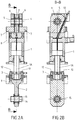
- FIG. 1 the front left section of the strand guide segment 50 is shown in a simplified perspective sectional view of the hydraulic cylinder unit 1 with its piston rod 1A, the flange device 3, the tie rod 2, the pivot bearings 4, 14, the bolts 5, 15 and the split bearing shells 6, 16.
- this sectional view is shown in detail in two dimensions.
- the flange device 3 is non-positively connected to the end section of the piston rod 1A facing away from the upper frame 8.
- the flange device 3 can have been thermally shrunk onto the end section of the piston rod 1A.
- the flange device 3 is connected by means of a plurality of screws 12, which are aligned in the axial direction of the piston rod 1A, to the widened end section of the tie rod 2 that faces away from the subframe 9.
- the Screws 12 establish a rigid connection between the piston rod 1A and the pull rod 2.
- the screws 12 can be loosened for maintenance work, so that the flange device 3 and thus also the piston rod 1A of the hydraulic cylinder unit 1 can be separated or decoupled from the pull rod 2.
- the upper frame 8 can be separated from the lower frame 9 during maintenance work without the bearings on the upper frame or lower frame having to be opened.
- FIG. 11 shows a view of a section along the lines BB in FIG Figure 2A .
- the position measurement sensor 10 is attached to the side of the bearing block 11 of the hydraulic cylinder unit 1 in the area of the upper frame 8. Therefore, the position measurement sensor 10 can be easily serviced in the continuous casting plant without dismantling the strand guide segment 50.
Landscapes
- Engineering & Computer Science (AREA)
- Mechanical Engineering (AREA)
- Continuous Casting (AREA)
Description
- Die vorliegende Erfindung betrifft ein Strangführungssegment für eine Stranggießanlage nach Gattung des unabhängigen Anspruchs 1. Gegenstand der Erfindung ist auch eine Stranggießanlage gemäß Anspruch 10.
- In heutigen Stranggießanlagen für Metalle, insbesondere Stahlwerkstoffe, wird das flüssige Metall zunächst in eine Kokille eingebracht und anschließend als Strang in teilerstarrter Form durch eine Strangführung, auch Stützrollengerüst genannt, mit Rollen geführt.
- Aus der
DE 19 63 146 C1 ist es bekannt, Teile des Stützrollengerüstes für mehrere Rollen zu Strangführungssegmenten zusammenzufassen, wobei jedes Strangführungssegment einen Oberrahmen und einen diesem gegenüberliegenden Unterrahmen aufweist, welche strangführende Rollen tragen, und deren Abstand zueinander über Zuganker und Distanzstücke auf das Gießformat einstellbar ist. Der Oberrahmen und der Unterrahmen eines jeweiligen Strangführungssegments werden durch vier an den äußeren Ecken außerhalb der Strangbahn angeordnete, den Oberrahmen und den Unterrahmen miteinander verbindende Hydraulikzylindereinheiten gegeneinander geklemmt. - Aus der
WO 2006/050868 A1 ist eine Strangführung mit Strangführungssegmenten bekannt, bei denen der jeweilige Oberrahmen und Unterrahmen über Hydraulikzylindereinheiten miteinander verbunden und gegeneinander geregelt anstellbar sind. Die Hydraulikzylindereinheiten sind an dem Oberrahmen und dem Unterrahmen gelagert montiert. - Zu Wartungszwecken an derartigen Strangführungssegmenten müssen der Oberrahmen und der Unterrahmen voneinander getrennt bzw. entkoppelt werden. Dazu müssen die jeweiligen Lagerungen der Hydraulikzylindereinheiten an dem Oberrahmen oder dem Unterrahmen geöffnet werden. Damit eine derartige Lagerung einfach geöffnet werden kann, muss für diese ein ausreichend großes Spiel vorgesehen sein. Eine derartige Realisierung wirkt sich aber nachteilig auf die Genauigkeit der durch das Strangführungssegment eingestellten Strangdicke aus. Daher können große Abweichungen zwischen der durch das Strangführungssegment tatsächlich eingestellten Strangdicke und der Sollstrangdicke auftreten.
- Aus der
EP1 754 556 A2 ist ein Strangführungssegment mit zwei Hydraulikzylindereinheiten zum Einstellen eines Abstands zwischen Oberrahmen und Unterrahmen bekannt, wobei die Hydraulikzylindereinheiten mittels einer Flanschvorrichtung lösbar mit dem Oberrahmen verbunden sind. Zusätzlich werden die Rahmen durch eine separate hydraulische Klemmvorrichtung miteinander verbunden. - Die
EP0 030 223 A2 offenbart ein Stütz- und Führungsgerüst für eine Stranggießanlage, mit einem oberem Tragwerk welches mittels eines daran befestigten Druckmittelzylinders über einen Zuganker und einer Strebe mit dem unteren Tragwerk lösbar befestigt ist. - Der vorliegenden Erfindung liegt daher die Aufgabe zugrunde, ein alternatives Strangführungssegment für eine Stranggießanlage bereitzustellen, das eine einfache Wartung und zugleich eine große Genauigkeit der durch das Strangführungssegment eingestellten Strangdicke gewährleistet. Außerdem soll die vorliegende Erfindung eine Stranggießanlage bereitzustellen, die einfach gewartet werden kann und eine hohe Genauigkeit der durch ihre Strangführungssegmente jeweils eingestellten Strangdicke gewährleistet.
- Die Aufgabe der vorliegenden Erfindung wird durch ein Strangführungssegment mit den Merkmalen des Anspruchs 1 gelöst. Vorteilhafte Weiterbildungen ergeben sich aus den Merkmalen der abhängigen Ansprüche, die beliebig kombiniert werden können.
- Das vorgestellte Strangführungssegment für eine Stranggießanlage für Metalle, insbesondere Stahlwerkstoffe, weist einen Oberrahmen und einen Unterrahmen auf, die während eines Gießbetriebs der Stranggießanlage über positionsgeregelte Hydraulikzylindereinheiten miteinander verbunden sind. Die Hydraulikzylindereinheiten sind angeordnet und ausgebildet zum Einstellen eines Abstands zwischen dem Oberrahmen und dem Unterrahmen, wobei der eingestellte Abstand eine Strangdicke eines durch das Strangführungssegment zu führenden Strangs vorgibt bzw. einstellt. Jede Hydraulikzylindereinheit weist eine Kolbenstange auf, die mittels eines aufgebrachten Hydraulikdrucks positionsgeregelt ausfahrbar bzw. einfahrbar ist, um den Abstand zwischen dem Oberrahmen und dem Unterrahmen zu vergrößern bzw. zu verkleinern. Bevorzugt weist das vorgestellte Strangführungssegment zwei Paare von Hydraulikzylindereinheiten auf, die beidseitig und außerhalb der Strangbahn des Strangführungssegments angeordnet sind. Bevorzugt hat das Strangführungssegment auf beiden Seiten der Strangbahn jeweils einen Seitenrahmen, die eine geführte Bewegung des Oberrahmens und des Unterrahmens relativ zueinander in Reaktion auf Auslenkungen bzw. Längenänderungen der Hydraulikzylindereinheiten zulassen. Ein erstes Ende jeder der Hydraulikzylindereinheiten ist an dem Oberrahmen gelagert. Ferner ist jede der Hydraulikzylindereinheiten, konkret ihre Kolbenstange, an ihrem von dem Oberrahmen abgewandten, zweiten Ende mittels einer jeweiligen Flanschvorrichtung mit einer jeweiligen Zugstange lösbar verbunden. Die Zugstangen sind an ihrem von der Flanschvorrichtung abgewandten Ende an dem Unterrahmen gelagert. Jede Hydraulikzylindereinheit, genauer genommen deren Kolbenstange, ist bevorzugt mittels der jeweiligen Flanschvorrichtung starr mit der jeweiligen Zugstange verbunden. Durch eine Positionsregelung bewirkte Längenänderungen der an dem Oberrahmen gelagerten Hydraulikzylindereinheiten werden über die an dem Unterrahmen gelagerten Zugstangen in eine entsprechende Veränderung des Abstands zwischen dem Oberrahmen und dem Unterrahmen umgesetzt. Die Zugstangen sind bevorzugt nicht längenveränderbar ausgestaltet.
- Die Bereitstellung der Flanschvorrichtungen, über die eine jeweilige Hydraulikzylindereinheit bzw. deren Kolbenstange mit einer jeweiligen Zugstange lösbar verbunden ist, ermöglicht eine einfache Trennung von Oberrrahmen und Unterrahmen, ohne dass die Lagerungen der Hydraulikzylindereinheiten am Oberrahmen geöffnet werden müssen. Somit brauchen die Lagerungen der Hydraulikzylindereinheiten nicht mit einem großen Spiel versehen sein. Die Lagerungen sind daher spielarm ausgestaltbar, wodurch das vorgestellte Strangführungssegment eine hohe Präzision der eingestellten Strangdicke gewährleistet.
- In einer Weiterbildung des vorgestellten Strangführungssegments ist vorgesehen, dass die Hydraulikzylindereinheiten, insbesondere deren Kolbenstangen, mit den jeweiligen Zugstangen über die jeweiligen Flanschvorrichtungen verschraubt sind. Durch die Verschraubungen werden ein einfaches Lösen der Hydraulikzylindervorrichtungen von den Zugstangen, gleichbedeutend mit einem einfachen Trennen des Oberrahmens von dem Unterrahmen, während der Wartung und zugleich eine sehr zugfeste Verbindung zwischen den Hydraulikzylindervorrichtungen und den Zugstangen während des Gießbetriebs ermöglicht.
- In einer Weiterbildung des vorgestellten Strangführungssegments ist vorgesehen, dass die Zugstangen mit ihrer jeweiligen Flanschvorrichtung lösbar verbunden sind. Zudem ist in einer Weiterbildung des vorgestellten Strangführungssegments vorgesehen, dass die Hydraulikzylindereinheiten mit der jeweiligen Flanschvorrichtung lösbar verbunden sind. Ist eine jeweilige Flanschverbindung sowohl mit der jeweiligen Zugstange als auch mit der jeweiligen Hydraulikzylindereinheit lösbar verbunden, so kann die Flanschverbindung besonders einfach bei Wartungsarbeiten ausgebaut und auf Verschleiss geprüft werden. Es kann auch vorgesehen sein, dass die jeweilige Flanschvorrichtung thermisch auf die jeweilige Hydraulikzylindereinheit, insbesondere auf deren Kolbenstange, aufgeschrumpft worden ist, und diese Flanschvorrichtung mit der jeweiligen Zugstange verschraubt ist. Es kann aber auch vorgesehen sein, dass die Flanschvorrichtung mit einer aus der Gruppe der Hydraulikzylindereinheit und der Zugstange fest verbunden ist, und die Flanschvorrichtung mit der anderen der Gruppe der Hydraulikzylindereinheit und der Zugstange lösbar verbunden, insbesondere verschraubt, ist.
- In einer Weiterbildung des vorgestellten Strangführungssegments ist vorgesehen, dass die Hydraulikzylindereinheiten an dem Oberrahmen mittels Gelenklagern auf Bolzen gelagert sind. Dadurch wird eine besonders spielarme Lagerung der Hydraulikzylindereinheiten realisiert, so dass das vorgestellte Strangführungssegment aufgrund der spielarmen Anbindung des Oberrahmens an den Unterrahmen eine hohe Präzision der eingestellten Strangdicke gewährleistet.
- In einer Weiterbildung des vorgestellten Strangführungssegments ist vorgesehen, dass die Zugstangen an dem Unterrahmen mittels Gelenklagern auf Bolzen gelagert sind. Dadurch wird eine besonders spielarme Lagerung der Zugstangen realisiert, so dass das vorgestellte Strangführungssegment aufgrund der spielarmen Anbindung des Unterrahmens an den Oberrahmen eine hohe Präzision der eingestellten Strangdicke gewährleistet.
- Bevorzugt werden sowohl die Hydraulikzylindereinheiten als auch die Zugstangen an ihrem zugeordneten Rahmen mittels Gelenklagern auf Bolzen gelagert. Dadurch gewährleistet das vorgestellte Strangführungssegment eine besonders hohe Präzision der eingestellten Strangdicke.
- Ferner ist in Weiterbildungen des vorgestellten Strangführungssegments vorgesehen, dass die Hydraulikzylindereinheiten und/oder die Zugstangen jeweils mit geteilten Lagerschalen und einem geteilten Lagerblock in ihrem zugeordneten Rahmen geklemmt sind. Dadurch wird eine spielarme Anbindung des Oberrahmens an den Unterrahmen erreicht, so dass das vorgestellte Strangführungssegment eine hohe Präzision der eingestellten Strangdicke ermöglicht. Zugleich können die Hydraulikzylindereinheiten und/oder die Zugstangen zu Wartungs- und Reparaturzwecken ohne großen technischen Aufwand von dem Oberrahmen bzw. Unterrahmen gelöst werden.
- In einer Weiterbildung des vorgestellten Strangführungssegments ist zudem vorgesehen, dass die Hydraulikzylindereinheiten an ihrem ersten Ende jeweils einen Lagerblock aufweisen, beispielsweise in der Form, dass das erste Ende einer jeweiligen Hydraulikzylindereinheit als ein Lagerblock für einen der oben erwähnten Bolzen ausgebildet ist. An diesem Lagerblock ist seitlich ein Positionsmessungssensor montiert, der die Auslenkung der Kolbenstange einer jeweiligen Hydraulikzylindereinheit misst und ein entsprechendes Messsignal zur Weiterleitung an einen Regler für eine Positionsregelung bzw. Strangdickenregelung erzeugt. Aufgrund der Montage der Positionsmessungssensoren seitlich an den oberen Lagerblöcken der Hydraulikzylindereinheiten ist eine einfache Wartung der Sensoren in der Stranggießanlage ohne Demontage des Strangführungssegments möglich.
- Ferner wird die Aufgabe der vorliegenden Erfindung auch durch eine Stranggießanlage gelöst, deren Strangführung mindestens eines der oben vorgestellten Strangführungssegmente aufweist. Bevorzugt ist die gesamte Strangführung aus mehreren der vorgestellten Strangführungssegmente zusammengesetzt. Die vorgestellte Stranggießanlage ermöglicht eine einfache Wartung der einzelnen Strangführungssegmente und eine Minimierung von Abweichungen zwischen tatsächlichen Strangdicken in der Strangführung und durch die Positionsregelung vorgegebenen Strangdicken.
- Die Erfindung umfasst beliebige Kombinationen des oben vorgestellten Strangführungssegments und der oben vorgestellten Stranggießanlage und der jeweiligen Weiterbildungen.
- Zur Verdeutlichung des vorgeschlagenen Strangführungssegments gemäß der vorliegenden Erfindung werden nun Ausführungsbeispiele mit Verweis auf die folgenden Figuren vorgestellt, in denen ähnliche oder identische Komponenten figurenübergreifend mit denselben Bezugszeichen versehen sind.
- Fig. 1
- veranschaulicht in perspektivischer Darstellung und mit vereinfachter Teilschnittansicht ein Ausführungsbeispiel des vorgestellten Strangführungssegments.
- Fig. 2A
- stellt eine detaillierte Schnittansicht des in
Fig. 1 als vereinfachte Teilschnittansicht dargestellten Abschnitts des Ausführungsbeispiels des vorgestellten Strangführungssegments dar. - Fig. 2B
- stellt eine seitliche Schnittansicht der in
Fig. 2A veranschaulichten Komponenten des Ausführungsbeispiels des vorgestellten Strangführungssegments dar. - In
Fig. 1 ist ein Ausführungsbeispiel des vorgestellten Strangführungssegments in perspektivischer Darstellung veranschaulicht. Das Strangführungssegment 50 weist einen Oberrahmen 8 und einen Unterrahmen 9 auf, deren Abstand zueinander entlang der Führung durch Seitenrahmen 20A und 20B veränderbar ist. Das Strangführungssegment 50 ist zum Führen eines Strangs, insbesondere aus teilerstarrtem Metall, und Einstellen der Strangdicke dieses Strangs ausgebildet. Zu diesem Zweck sind an dem Oberrahmen 8 gelagerte Rollen 21 und an dem Unterrahmen 9 gelagerte Rollen 22 vorgesehen, zwischen denen der Strang geführt wird, und wobei Abstand zwischen den Rollen 21 und 22 die durch das Strangführungssegment 50 eingestellte Strangdicke bestimmt. Der Abstand wird durch vier Hydraulikzylindereinheiten 1 mit damit jeweils verbundenen Zugstangen 2 eingestellt, die an den vier äußeren Ecken des Strangführungssegments 50 angeordnet sind. - Die Hydraulikzylindereinheiten 1 sind mittels einer jeweiligen Flanschvorrichtung 3 lösbar mit der jeweiligen Zugstange 2 verbunden. Das dem Oberrahmen 8 zugewandte Ende jeder Hydraulikzylindereinheit 1 ist als Lagerblock 11 ausgestaltet, an dem seitlich ein Positionsmessungssensor 10 montiert ist. Der Lagerblock 11 ist zur Aufnahme eines Bolzen 5 ausgebildet, der wiederum durch geteilte Lagerschalen 6 und einen geteilten Lagerblock 7, die an dem Oberrahmen 8 vorgesehen bzw. montiert sind, in dem Oberrahmen 8 geklemmt ist. Der Lagerblock 11 einer jeweiligen Hydraulikzylindereinheit 1 ist mittels eines spielarm ausgestalteten Gelenklagers 4 auf dem Bolzen 5 gelagert. Jede Hydraulikzylindereinheit 1 ist axial in Richtung des Unterrahmens 9 ausgerichtet, wobei jede Hydraulikzylindereinheit 1 an ihrem von dem Oberrahmen 2 abgewandten Ende eine Kolbenstange 1A aufweist. Diese Kolbenstange 1A ist mit der Flanschvorrichtung 3 verbunden, die wiederum mit der Zugstange 2 verbunden ist.
- Die Zugstange 2 ist an ihrem von der Flanschvorrichtung 3 abgewandten Ende an dem Unterrahmen 9 gelagert. Genauer genommen ist die Zugstange 2 an diesem Ende mittels eines spielarmen Gelenklagers 14 auf einem Bolzen 15 gelagert. Der Bolzen 15, und somit auch die Zugstange 2, ist mittels geteilter Lagerschalen 16 und eines geteilten Lagerblocks 17 in dem Unterrahmen 9 geklemmt.
- In
Fig. 1 ist der vordere linke Abschnitt des Strangführungssegments 50 in einer vereinfachten perspektivischen Schnittansicht der Hydraulikzylindereinheit 1 mit ihrer Kolbenstange 1A, der Flanschvorrichtung 3, der Zugstange 2, den Gelenklagern 4,14, der Bolzen 5, 15 und der geteilten Lagerschalen 6, 16 dargestellt. InFig. 2A ist diese Schnittansicht hingegen detailliert zweidimensional dargestellt. Bei dem veranschaulichten Ausführungsbeispiel ist die Flanschvorrichtung 3 kraftschlüssig mit dem von dem Oberrahmen 8 abgewandten Endabschnitt der Kolbenstange 1A verbunden. Beispielsweise kann die Flanschvorrichtung 3 thermisch auf den Endabschnitt der Kolbenstange 1A aufgeschrumpft worden sein. Die Flanschvorrichtung 3 ist mittels mehrerer Schrauben 12, die in axialer Richtung der Kolbenstange 1A ausgerichtet sind, mit dem von dem Unterrahmen 9 abgewandten und verbreitert ausgestalteten Endabschnitt der Zugstange 2 verbunden. Während des Gießbetriebs stellen die Schrauben 12 eine starre Verbindung zwischen der Kolbenstange 1A und der Zugstange 2 her. Für Wartungsarbeiten können die Schrauben 12 gelöst werden, so dass die Flanschvorrichtung 3 und somit auch die Kolbenstange 1A der Hydraulikzylindereinheit 1 von der Zugstange 2 getrennt bzw. entkoppelt werden kann. Dadurch kann bei Wartungsarbeiten der Oberrahmen 8 von dem Unterrahmen 9 getrennt werden, ohne dass die Lagerungen am Oberrahmen oder Unterrahmen geöffnet werden müssen. -
Fig. 2B zeigt eine Ansicht auf einen Schnitt entlang der Linien B-B inFig. 2A . Wie ausFig. 2B ersichtlich, ist der Positionsmessungssensor 10 seitlich am Lagerblock 11 der Hydraulikzylindereinheit 1 im Bereich des Oberrahmens 8 angebracht. Daher kann der Positionsmessungssensor 10 einfach in der Stranggießanlage ohne Demontage des Strangführungssegments 50 gewartet werden. -
- 1
- Hydraulikzylindereinheit
- 1A
- Kolbenstange der Hydraulikzylindereinheit
- 2
- Zugstange
- 3
- Flanschvorrichtung
- 4, 14
- Gelenklager
- 5, 15
- Bolzen
- 6, 16
- geteilte Lagerschalen
- 7, 17
- geteilter Lagerblock
- 8
- Oberrrahmen
- 9
- Unterrahmen
- 10
- Positionsmessungssensor
- 11
- Lagerblock
- 12
- Schraube
- 20A, 20B
- Seitenrahmen
- 21,22
- Rollen
- 50
- Strangführungssegement
Claims (10)
- Strangführungssegment (50) für eine Stranggießanlage, mit einem Oberrahmen (8), einem Unterrahmen (9) und positionsgeregelten Hydraulikzylindereinheiten (1, 1A) zum Einstellen eines Abstands zwischen dem Oberrahmen (8) und dem Unterrahmen (9) und dadurch einer Strangdicke eines durch das Strangführungssegment (50) zu führenden Strangs, wobei ein erstes Ende jeder Hydraulikzylindereinheit (1, 1A) an dem Oberrahmen (8) gelagert ist, dadurch gekennzeichnet, dass jede Hydraulikzylindereinheit (1, 1A) an ihrem von dem Oberrahmen (8) abgewandten, zweiten Ende mittels einer jeweiligen Flanschvorrichtung (3) mit einer jeweiligen Zugstange (2) lösbar verbunden ist, die an ihrem von der Flanschvorrichtung (3) abgewandten Ende an dem Unterrahmen (9) gelagert ist.
- Strangführungssegment (50) nach Anspruch 1, dadurch gekennzeichnet, dass die Hydraulikzylindereinheiten (1, 1A) mit den jeweiligen Zugstangen (2) über die jeweiligen Flanschvorrichtungen (3) verschraubt sind.
- Strangführungssegment (50) nach Anspruch 1 oder 2, dadurch gekennzeichnet, dass die Zugstangen (2) mit der jeweiligen Flanschvorrichtung (3) lösbar verbunden sind.
- Strangführungssegment (50) nach einem der Ansprüche 1 bis 3, dadurch gekennzeichnet, dass die Hydraulikzylindereinheiten (1, 1A) mit der jeweiligen Flanschvorrichtung (3) lösbar verbunden sind.
- Strangführungssegment (50) nach einem der Ansprüche 1 bis 4, dadurch gekennzeichnet, dass die Hydraulikzylindereinheiten (1, 1A) mittels Gelenklagern (4) auf Bolzen (5) an dem Oberrahmen (8) gelagert sind.
- Strangführungssegment (50) nach einem der Ansprüche 1 bis 5, dadurch gekennzeichnet, dass die Zugstangen (2) mittels Gelenklagern (14) auf Bolzen (15) an dem Unterrahmen (9) gelagert sind.
- Strangführungssegment (50) nach einem der Ansprüche 1 bis 6, dadurch gekennzeichnet, dass die Hydraulikzylindereinheiten (1, 1A) jeweils mit geteilten Lagerschalen (6) und einem geteilten Lagerblock (7) in dem Oberrahmen (8) geklemmt sind.
- Strangführungssegment (50) nach einem der Ansprüche 1 bis 7, dadurch gekennzeichnet, dass die Zugstangen (2) jeweils mit geteilten Lagerschalen (16) und einem geteilten Lagerblock (17) in dem Unterrahmen (9) geklemmt sind.
- Strangführungssegment nach einem der Ansprüche 1 bis 8, dadurch gekennzeichnet, dass die Hydraulikzylindereinheiten (1, 1A) an ihrem ersten Ende jeweils einen Lagerblock (11) mit einem seitlich montierten Positionsmessungssensor (10) aufweisen.
- Stranggießanlage mit einer Strangführung, die mindestens ein Strangführungssegment (50) nach einem der Ansprüche 1 bis 9 aufweist.
Applications Claiming Priority (2)
| Application Number | Priority Date | Filing Date | Title |
|---|---|---|---|
| DE102017219740.4A DE102017219740A1 (de) | 2017-11-07 | 2017-11-07 | Strangführungssegment und Stranggießanlage |
| PCT/EP2018/076752 WO2019091664A1 (de) | 2017-11-07 | 2018-10-02 | STRANGFÜHRUNGSSEGMENT UND STRANGGIEßANLAGE |
Publications (2)
| Publication Number | Publication Date |
|---|---|
| EP3706933A1 EP3706933A1 (de) | 2020-09-16 |
| EP3706933B1 true EP3706933B1 (de) | 2021-12-08 |
Family
ID=63762508
Family Applications (1)
| Application Number | Title | Priority Date | Filing Date |
|---|---|---|---|
| EP18782390.1A Active EP3706933B1 (de) | 2017-11-07 | 2018-10-02 | Strangführungssegment und stranggiessanlage |
Country Status (5)
| Country | Link |
|---|---|
| US (1) | US11565309B2 (de) |
| EP (1) | EP3706933B1 (de) |
| DE (1) | DE102017219740A1 (de) |
| RU (1) | RU2741608C1 (de) |
| WO (1) | WO2019091664A1 (de) |
Family Cites Families (9)
| Publication number | Priority date | Publication date | Assignee | Title |
|---|---|---|---|---|
| DE1963146C3 (de) | 1969-12-17 | 1974-02-28 | Demag Ag, 4100 Duisburg | Segmentrahmen für die Stütz- bzw. Transportwalzen einer Metall-, insbesondere Stahlstranggießanlage |
| AT368049B (de) * | 1979-11-28 | 1982-08-25 | Voest Alpine Ag | Einrichtung an einem stuetz- und fuehrungsgeruest fuer eine stranggiessanlage |
| US5115857A (en) | 1990-07-18 | 1992-05-26 | Voest-Alpine Industrieanlagenbau G.M.B.H. | Strand guide arrangement provided at a continuous casting plant |
| SU1759539A1 (ru) * | 1991-01-22 | 1992-09-07 | Центральный научно-исследовательский институт металлургии и материалов | Правильно-т нуща секци машины непрерывного лить заготовок |
| DE4306853C2 (de) | 1993-02-26 | 1996-03-21 | Mannesmann Ag | Strangführungsgerüst |
| DE19824366A1 (de) * | 1998-05-30 | 1999-12-02 | Schloemann Siemag Ag | Strangführungssegment für Brammengießanlagen |
| DE102004054296B4 (de) | 2004-11-09 | 2021-11-11 | Sms Group Gmbh | Steuer- und / oder Regeleinrichtung für ein Stützrollengerüst einer Stranggießvorrichtung für Metalle, insbesondere für Stahlwerkstoffe |
| DE102005039473A1 (de) * | 2005-08-20 | 2007-02-22 | Sms Demag Ag | Vorrichtung für ein schnelles Verbinden oder ein schnelles Lösen von zwei grossen, schweren Bauteilen für den Hüttenwerksbetrieb, insbesondere für eine Stahl-Stranggiessmaschine |
| AT515260B1 (de) * | 2013-12-17 | 2017-12-15 | Primetals Technologies Austria GmbH | Steuer- oder Regeleinrichtung für ein Stützrollengerüst einer Stranggießmaschine |
-
2017
- 2017-11-07 DE DE102017219740.4A patent/DE102017219740A1/de not_active Withdrawn
-
2018
- 2018-10-02 WO PCT/EP2018/076752 patent/WO2019091664A1/de not_active Ceased
- 2018-10-02 US US16/761,838 patent/US11565309B2/en active Active
- 2018-10-02 EP EP18782390.1A patent/EP3706933B1/de active Active
- 2018-10-02 RU RU2020115495A patent/RU2741608C1/ru active
Also Published As
| Publication number | Publication date |
|---|---|
| DE102017219740A1 (de) | 2019-05-09 |
| US11565309B2 (en) | 2023-01-31 |
| RU2741608C1 (ru) | 2021-01-27 |
| WO2019091664A1 (de) | 2019-05-16 |
| US20210197251A1 (en) | 2021-07-01 |
| EP3706933A1 (de) | 2020-09-16 |
Similar Documents
| Publication | Publication Date | Title |
|---|---|---|
| EP1043095B1 (de) | Vorrichtung zum Einstellen des Brammenprofils einer stranggegossenen Bramme, insbesondere einer Dünnbramme | |
| AT516412B1 (de) | Strangführungsrolleneinheit für eine Stranggießmaschine | |
| EP0734800B1 (de) | Strangführung einer Stranggiessanlage für Dünnbrammen | |
| DE4306853C2 (de) | Strangführungsgerüst | |
| EP0908256B1 (de) | Verfahren und Anlage zur Erzeugung von Brammen in einer Stranggiessanlage | |
| DE2644096C2 (de) | Stütz- und Führungsbogen für Gußstränge, insbesondere für Brammengußstränge | |
| EP2276594B1 (de) | Stranggiessanlage zum giessen eines metallstranges mit knüppel- oder vorblockquerschnitt | |
| EP2257398A1 (de) | Strangführung, insbesondere für eine stahlbrammen-stranggiessanlage | |
| DE2021780C3 (de) | Verfahren zur Anpassung der Bogenfühning eines aus einer Stranggießkokille austretenden Stranges und Vorrichtung dazu | |
| EP1370379A2 (de) | Verfahren zum giessen und unmittelbar anschliessendem walzen und eine vorrichtung zur stützung, führung und verformung eines metall-, insbesondere eines stahlstranges | |
| EP2525928B2 (de) | Strangführungselement zum führen und stützen eines metallischen strangs in einer stranggiessmaschine | |
| EP0960671A2 (de) | Strangführungssegment für Brammengiessanlagen | |
| WO2002090019A1 (de) | VERFAHREN UND VORRICHTUNG ZUM STRANGGIEssEN VON BLÖCKEN, BRAMMEN ODER DÜNNBRAMMEN | |
| DE102014202995A1 (de) | Rahmen für ein Strangführungssegment | |
| WO2019091664A1 (de) | STRANGFÜHRUNGSSEGMENT UND STRANGGIEßANLAGE | |
| AT521416B1 (de) | Strangführungssegment mit individuell verschiebbaren Strangführungsrollen | |
| DE10024514C2 (de) | Stranggießanlage | |
| EP0949024B1 (de) | Stützführung für den Giessstrang einer Stranggiessanlage | |
| EP3613519B1 (de) | Strangführungselement einer stranggiessanlage | |
| EP2648865B1 (de) | Stranggiessanlage zum giessen eines metallstranges | |
| DE102010063093B4 (de) | Vorrichtung und Verfahren zum horizontalen Gießen von Metallbändern | |
| EP1286796A1 (de) | Strangführung für eine stranggiessanlage | |
| DE19717914A1 (de) | Vorrichtung zum Ausziehen eines Stranges | |
| DE202012012284U1 (de) | Strangführung für eine Stranggießanlage | |
| DE3125322A1 (de) | Stahlstranggiessanlage |
Legal Events
| Date | Code | Title | Description |
|---|---|---|---|
| STAA | Information on the status of an ep patent application or granted ep patent |
Free format text: STATUS: UNKNOWN |
|
| STAA | Information on the status of an ep patent application or granted ep patent |
Free format text: STATUS: THE INTERNATIONAL PUBLICATION HAS BEEN MADE |
|
| PUAI | Public reference made under article 153(3) epc to a published international application that has entered the european phase |
Free format text: ORIGINAL CODE: 0009012 |
|
| STAA | Information on the status of an ep patent application or granted ep patent |
Free format text: STATUS: REQUEST FOR EXAMINATION WAS MADE |
|
| 17P | Request for examination filed |
Effective date: 20200608 |
|
| AK | Designated contracting states |
Kind code of ref document: A1 Designated state(s): AL AT BE BG CH CY CZ DE DK EE ES FI FR GB GR HR HU IE IS IT LI LT LU LV MC MK MT NL NO PL PT RO RS SE SI SK SM TR |
|
| AX | Request for extension of the european patent |
Extension state: BA ME |
|
| DAV | Request for validation of the european patent (deleted) | ||
| DAX | Request for extension of the european patent (deleted) | ||
| GRAP | Despatch of communication of intention to grant a patent |
Free format text: ORIGINAL CODE: EPIDOSNIGR1 |
|
| STAA | Information on the status of an ep patent application or granted ep patent |
Free format text: STATUS: GRANT OF PATENT IS INTENDED |
|
| INTG | Intention to grant announced |
Effective date: 20210628 |
|
| GRAS | Grant fee paid |
Free format text: ORIGINAL CODE: EPIDOSNIGR3 |
|
| GRAA | (expected) grant |
Free format text: ORIGINAL CODE: 0009210 |
|
| STAA | Information on the status of an ep patent application or granted ep patent |
Free format text: STATUS: THE PATENT HAS BEEN GRANTED |
|
| AK | Designated contracting states |
Kind code of ref document: B1 Designated state(s): AL AT BE BG CH CY CZ DE DK EE ES FI FR GB GR HR HU IE IS IT LI LT LU LV MC MK MT NL NO PL PT RO RS SE SI SK SM TR |
|
| REG | Reference to a national code |
Ref country code: GB Ref legal event code: FG4D Free format text: NOT ENGLISH |
|
| REG | Reference to a national code |
Ref country code: AT Ref legal event code: REF Ref document number: 1453368 Country of ref document: AT Kind code of ref document: T Effective date: 20211215 Ref country code: CH Ref legal event code: EP |
|
| REG | Reference to a national code |
Ref country code: DE Ref legal event code: R096 Ref document number: 502018008153 Country of ref document: DE |
|
| REG | Reference to a national code |
Ref country code: IE Ref legal event code: FG4D Free format text: LANGUAGE OF EP DOCUMENT: GERMAN |
|
| REG | Reference to a national code |
Ref country code: LT Ref legal event code: MG9D |
|
| REG | Reference to a national code |
Ref country code: NL Ref legal event code: MP Effective date: 20211208 |
|
| PG25 | Lapsed in a contracting state [announced via postgrant information from national office to epo] |
Ref country code: RS Free format text: LAPSE BECAUSE OF FAILURE TO SUBMIT A TRANSLATION OF THE DESCRIPTION OR TO PAY THE FEE WITHIN THE PRESCRIBED TIME-LIMIT Effective date: 20211208 Ref country code: LT Free format text: LAPSE BECAUSE OF FAILURE TO SUBMIT A TRANSLATION OF THE DESCRIPTION OR TO PAY THE FEE WITHIN THE PRESCRIBED TIME-LIMIT Effective date: 20211208 Ref country code: FI Free format text: LAPSE BECAUSE OF FAILURE TO SUBMIT A TRANSLATION OF THE DESCRIPTION OR TO PAY THE FEE WITHIN THE PRESCRIBED TIME-LIMIT Effective date: 20211208 Ref country code: BG Free format text: LAPSE BECAUSE OF FAILURE TO SUBMIT A TRANSLATION OF THE DESCRIPTION OR TO PAY THE FEE WITHIN THE PRESCRIBED TIME-LIMIT Effective date: 20220308 |
|
| PG25 | Lapsed in a contracting state [announced via postgrant information from national office to epo] |
Ref country code: SE Free format text: LAPSE BECAUSE OF FAILURE TO SUBMIT A TRANSLATION OF THE DESCRIPTION OR TO PAY THE FEE WITHIN THE PRESCRIBED TIME-LIMIT Effective date: 20211208 Ref country code: NO Free format text: LAPSE BECAUSE OF FAILURE TO SUBMIT A TRANSLATION OF THE DESCRIPTION OR TO PAY THE FEE WITHIN THE PRESCRIBED TIME-LIMIT Effective date: 20220308 Ref country code: LV Free format text: LAPSE BECAUSE OF FAILURE TO SUBMIT A TRANSLATION OF THE DESCRIPTION OR TO PAY THE FEE WITHIN THE PRESCRIBED TIME-LIMIT Effective date: 20211208 Ref country code: HR Free format text: LAPSE BECAUSE OF FAILURE TO SUBMIT A TRANSLATION OF THE DESCRIPTION OR TO PAY THE FEE WITHIN THE PRESCRIBED TIME-LIMIT Effective date: 20211208 Ref country code: GR Free format text: LAPSE BECAUSE OF FAILURE TO SUBMIT A TRANSLATION OF THE DESCRIPTION OR TO PAY THE FEE WITHIN THE PRESCRIBED TIME-LIMIT Effective date: 20220309 |
|
| PG25 | Lapsed in a contracting state [announced via postgrant information from national office to epo] |
Ref country code: NL Free format text: LAPSE BECAUSE OF FAILURE TO SUBMIT A TRANSLATION OF THE DESCRIPTION OR TO PAY THE FEE WITHIN THE PRESCRIBED TIME-LIMIT Effective date: 20211208 |
|
| PG25 | Lapsed in a contracting state [announced via postgrant information from national office to epo] |
Ref country code: SM Free format text: LAPSE BECAUSE OF FAILURE TO SUBMIT A TRANSLATION OF THE DESCRIPTION OR TO PAY THE FEE WITHIN THE PRESCRIBED TIME-LIMIT Effective date: 20211208 Ref country code: SK Free format text: LAPSE BECAUSE OF FAILURE TO SUBMIT A TRANSLATION OF THE DESCRIPTION OR TO PAY THE FEE WITHIN THE PRESCRIBED TIME-LIMIT Effective date: 20211208 Ref country code: RO Free format text: LAPSE BECAUSE OF FAILURE TO SUBMIT A TRANSLATION OF THE DESCRIPTION OR TO PAY THE FEE WITHIN THE PRESCRIBED TIME-LIMIT Effective date: 20211208 Ref country code: PT Free format text: LAPSE BECAUSE OF FAILURE TO SUBMIT A TRANSLATION OF THE DESCRIPTION OR TO PAY THE FEE WITHIN THE PRESCRIBED TIME-LIMIT Effective date: 20220408 Ref country code: ES Free format text: LAPSE BECAUSE OF FAILURE TO SUBMIT A TRANSLATION OF THE DESCRIPTION OR TO PAY THE FEE WITHIN THE PRESCRIBED TIME-LIMIT Effective date: 20211208 Ref country code: EE Free format text: LAPSE BECAUSE OF FAILURE TO SUBMIT A TRANSLATION OF THE DESCRIPTION OR TO PAY THE FEE WITHIN THE PRESCRIBED TIME-LIMIT Effective date: 20211208 Ref country code: CZ Free format text: LAPSE BECAUSE OF FAILURE TO SUBMIT A TRANSLATION OF THE DESCRIPTION OR TO PAY THE FEE WITHIN THE PRESCRIBED TIME-LIMIT Effective date: 20211208 |
|
| PG25 | Lapsed in a contracting state [announced via postgrant information from national office to epo] |
Ref country code: PL Free format text: LAPSE BECAUSE OF FAILURE TO SUBMIT A TRANSLATION OF THE DESCRIPTION OR TO PAY THE FEE WITHIN THE PRESCRIBED TIME-LIMIT Effective date: 20211208 |
|
| REG | Reference to a national code |
Ref country code: DE Ref legal event code: R097 Ref document number: 502018008153 Country of ref document: DE |
|
| PG25 | Lapsed in a contracting state [announced via postgrant information from national office to epo] |
Ref country code: IS Free format text: LAPSE BECAUSE OF FAILURE TO SUBMIT A TRANSLATION OF THE DESCRIPTION OR TO PAY THE FEE WITHIN THE PRESCRIBED TIME-LIMIT Effective date: 20220408 |
|
| PLBE | No opposition filed within time limit |
Free format text: ORIGINAL CODE: 0009261 |
|
| STAA | Information on the status of an ep patent application or granted ep patent |
Free format text: STATUS: NO OPPOSITION FILED WITHIN TIME LIMIT |
|
| PG25 | Lapsed in a contracting state [announced via postgrant information from national office to epo] |
Ref country code: DK Free format text: LAPSE BECAUSE OF FAILURE TO SUBMIT A TRANSLATION OF THE DESCRIPTION OR TO PAY THE FEE WITHIN THE PRESCRIBED TIME-LIMIT Effective date: 20211208 Ref country code: AL Free format text: LAPSE BECAUSE OF FAILURE TO SUBMIT A TRANSLATION OF THE DESCRIPTION OR TO PAY THE FEE WITHIN THE PRESCRIBED TIME-LIMIT Effective date: 20211208 |
|
| 26N | No opposition filed |
Effective date: 20220909 |
|
| PG25 | Lapsed in a contracting state [announced via postgrant information from national office to epo] |
Ref country code: SI Free format text: LAPSE BECAUSE OF FAILURE TO SUBMIT A TRANSLATION OF THE DESCRIPTION OR TO PAY THE FEE WITHIN THE PRESCRIBED TIME-LIMIT Effective date: 20211208 |
|
| PG25 | Lapsed in a contracting state [announced via postgrant information from national office to epo] |
Ref country code: MC Free format text: LAPSE BECAUSE OF FAILURE TO SUBMIT A TRANSLATION OF THE DESCRIPTION OR TO PAY THE FEE WITHIN THE PRESCRIBED TIME-LIMIT Effective date: 20211208 |
|
| REG | Reference to a national code |
Ref country code: CH Ref legal event code: PL |
|
| REG | Reference to a national code |
Ref country code: BE Ref legal event code: MM Effective date: 20221031 |
|
| GBPC | Gb: european patent ceased through non-payment of renewal fee |
Effective date: 20221002 |
|
| PG25 | Lapsed in a contracting state [announced via postgrant information from national office to epo] |
Ref country code: LU Free format text: LAPSE BECAUSE OF NON-PAYMENT OF DUE FEES Effective date: 20221002 |
|
| PG25 | Lapsed in a contracting state [announced via postgrant information from national office to epo] |
Ref country code: LI Free format text: LAPSE BECAUSE OF NON-PAYMENT OF DUE FEES Effective date: 20221031 Ref country code: FR Free format text: LAPSE BECAUSE OF NON-PAYMENT OF DUE FEES Effective date: 20221031 Ref country code: CH Free format text: LAPSE BECAUSE OF NON-PAYMENT OF DUE FEES Effective date: 20221031 |
|
| P01 | Opt-out of the competence of the unified patent court (upc) registered |
Effective date: 20230707 |
|
| PG25 | Lapsed in a contracting state [announced via postgrant information from national office to epo] |
Ref country code: BE Free format text: LAPSE BECAUSE OF NON-PAYMENT OF DUE FEES Effective date: 20221031 |
|
| PG25 | Lapsed in a contracting state [announced via postgrant information from national office to epo] |
Ref country code: IE Free format text: LAPSE BECAUSE OF NON-PAYMENT OF DUE FEES Effective date: 20221002 Ref country code: GB Free format text: LAPSE BECAUSE OF NON-PAYMENT OF DUE FEES Effective date: 20221002 |
|
| PG25 | Lapsed in a contracting state [announced via postgrant information from national office to epo] |
Ref country code: CY Free format text: LAPSE BECAUSE OF FAILURE TO SUBMIT A TRANSLATION OF THE DESCRIPTION OR TO PAY THE FEE WITHIN THE PRESCRIBED TIME-LIMIT Effective date: 20211208 |
|
| PG25 | Lapsed in a contracting state [announced via postgrant information from national office to epo] |
Ref country code: MK Free format text: LAPSE BECAUSE OF FAILURE TO SUBMIT A TRANSLATION OF THE DESCRIPTION OR TO PAY THE FEE WITHIN THE PRESCRIBED TIME-LIMIT Effective date: 20211208 Ref country code: HU Free format text: LAPSE BECAUSE OF FAILURE TO SUBMIT A TRANSLATION OF THE DESCRIPTION OR TO PAY THE FEE WITHIN THE PRESCRIBED TIME-LIMIT; INVALID AB INITIO Effective date: 20181002 |
|
| PG25 | Lapsed in a contracting state [announced via postgrant information from national office to epo] |
Ref country code: MT Free format text: LAPSE BECAUSE OF FAILURE TO SUBMIT A TRANSLATION OF THE DESCRIPTION OR TO PAY THE FEE WITHIN THE PRESCRIBED TIME-LIMIT Effective date: 20211208 |
|
| PG25 | Lapsed in a contracting state [announced via postgrant information from national office to epo] |
Ref country code: TR Free format text: LAPSE BECAUSE OF FAILURE TO SUBMIT A TRANSLATION OF THE DESCRIPTION OR TO PAY THE FEE WITHIN THE PRESCRIBED TIME-LIMIT Effective date: 20211208 |
|
| PGFP | Annual fee paid to national office [announced via postgrant information from national office to epo] |
Ref country code: DE Payment date: 20251021 Year of fee payment: 8 |
|
| PGFP | Annual fee paid to national office [announced via postgrant information from national office to epo] |
Ref country code: AT Payment date: 20251022 Year of fee payment: 8 |
|
| PGFP | Annual fee paid to national office [announced via postgrant information from national office to epo] |
Ref country code: IT Payment date: 20251024 Year of fee payment: 8 |