EP3706601B1 - Sitzmöbelträgeranordnung - Google Patents
Sitzmöbelträgeranordnung Download PDFInfo
- Publication number
- EP3706601B1 EP3706601B1 EP18873018.8A EP18873018A EP3706601B1 EP 3706601 B1 EP3706601 B1 EP 3706601B1 EP 18873018 A EP18873018 A EP 18873018A EP 3706601 B1 EP3706601 B1 EP 3706601B1
- Authority
- EP
- European Patent Office
- Prior art keywords
- longitudinal beam
- elastic sheet
- seating furniture
- support arrangement
- tension
- Prior art date
- Legal status (The legal status is an assumption and is not a legal conclusion. Google has not performed a legal analysis and makes no representation as to the accuracy of the status listed.)
- Active
Links
Images


Classifications
-
- A—HUMAN NECESSITIES
- A47—FURNITURE; DOMESTIC ARTICLES OR APPLIANCES; COFFEE MILLS; SPICE MILLS; SUCTION CLEANERS IN GENERAL
- A47C—CHAIRS; SOFAS; BEDS
- A47C4/00—Foldable, collapsible or dismountable chairs
- A47C4/02—Dismountable chairs
- A47C4/028—Upholstered chairs, e.g. metal, plastic or wooden chairs
-
- A—HUMAN NECESSITIES
- A47—FURNITURE; DOMESTIC ARTICLES OR APPLIANCES; COFFEE MILLS; SPICE MILLS; SUCTION CLEANERS IN GENERAL
- A47C—CHAIRS; SOFAS; BEDS
- A47C31/00—Details or accessories for chairs, beds, or the like, not provided for in other groups of this subclass, e.g. upholstery fasteners, mattress protectors, stretching devices for mattress nets
- A47C31/02—Upholstery attaching means
- A47C31/023—Upholstery attaching means connecting upholstery to frames, e.g. by hooks, clips, snap fasteners, clamping means or the like
-
- A—HUMAN NECESSITIES
- A47—FURNITURE; DOMESTIC ARTICLES OR APPLIANCES; COFFEE MILLS; SPICE MILLS; SUCTION CLEANERS IN GENERAL
- A47C—CHAIRS; SOFAS; BEDS
- A47C31/00—Details or accessories for chairs, beds, or the like, not provided for in other groups of this subclass, e.g. upholstery fasteners, mattress protectors, stretching devices for mattress nets
- A47C31/02—Upholstery attaching means
- A47C31/026—Upholstery attaching means passing through the upholstery, e.g. upholstery nails or buttons
-
- A—HUMAN NECESSITIES
- A47—FURNITURE; DOMESTIC ARTICLES OR APPLIANCES; COFFEE MILLS; SPICE MILLS; SUCTION CLEANERS IN GENERAL
- A47C—CHAIRS; SOFAS; BEDS
- A47C4/00—Foldable, collapsible or dismountable chairs
- A47C4/28—Folding chairs with flexible coverings for the seat or back elements
- A47C4/30—Attachment of upholstery or fabric to frames
-
- A—HUMAN NECESSITIES
- A47—FURNITURE; DOMESTIC ARTICLES OR APPLIANCES; COFFEE MILLS; SPICE MILLS; SUCTION CLEANERS IN GENERAL
- A47C—CHAIRS; SOFAS; BEDS
- A47C5/00—Chairs of special materials
- A47C5/04—Metal chairs, e.g. tubular
- A47C5/06—Special adaptation of seat upholstery or fabric for attachment to tubular chairs
-
- A—HUMAN NECESSITIES
- A47—FURNITURE; DOMESTIC ARTICLES OR APPLIANCES; COFFEE MILLS; SPICE MILLS; SUCTION CLEANERS IN GENERAL
- A47C—CHAIRS; SOFAS; BEDS
- A47C7/00—Parts, details, or accessories of chairs or stools
- A47C7/02—Seat parts
- A47C7/22—Straps or the like for direct user support or for carrying upholstery
-
- A—HUMAN NECESSITIES
- A47—FURNITURE; DOMESTIC ARTICLES OR APPLIANCES; COFFEE MILLS; SPICE MILLS; SUCTION CLEANERS IN GENERAL
- A47C—CHAIRS; SOFAS; BEDS
- A47C7/00—Parts, details, or accessories of chairs or stools
- A47C7/02—Seat parts
- A47C7/28—Seat parts with tensioned springs, e.g. of flat type
- A47C7/282—Seat parts with tensioned springs, e.g. of flat type with mesh-like supports, e.g. elastomeric membranes
Definitions
- the present invention relates to a seating furniture support arrangement for a seat or a backrest.
- Sofa support arrangements where stretched sheets provide support for a sofa seat and/or a sofa backrest are known in the prior art. They may be designed to be assembled by persons not specially trained for the task at the point of future use.
- a sofa 102 frame comprises a first short-end section 104a, a second short-end section 104b and a support arrangement 106 comprising a first longitudinal beam 108, a second longitudinal beam 110, and a third longitudinal beam 112, all beams running between the first short-end section 104a and the second short-end section 104b and thus carrying the load of the seat and its occupant(s) to the short-end sections 104a, 104b.
- a first sheet 114 may be stretched between the first longitudinal beam 108 and the second longitudinal beam 110 and a second sheet 116 may be stretched between the first longitudinal beam 108 and the third longitudinal beam 112 forming, respectively, a support for a seat and for a backrest.
- the seat and/or backrest may be formed by placing pillows on the sheets 114, 116.
- the first longitudinal beam may be manually pulled and fixed with a screw 120.
- the invention provides a sofa seating furniture support arrangement for a seat or a backrest, comprising a first and a second load-carrying longitudinal beam, each being mountable to a seating furniture frame comprising one or more parts; an elastic sheet for providing support for one of the seat and the backrest; and a mechanism for stretching the elastic sheet between the first longitudinal beam and the second longitudinal beam.
- the mechanism comprises a stretching member pivotable on the frame around a pivot axis.
- the elastic sheet is, with the sofa seating furniture support arrangement in installed position, connected to the first longitudinal beam offset to said pivot axis so that the first longitudinal beam pivoting with respect to the frame, in response to an application of an external force or torque, stretches the elastic sheet, with the external force or torque working against the tension force of the elastic sheet until a point of maximum tension is reached, past which point of maximum tension the tension force facilitates further pivoting of the first longitudinal beam, acting to keep the first longitudinal beam in place in a final position.
- a large degree of elasticity is not required in the elastic sheets, i.e., their coefficient of elasticity, defined as the ratio of tension force to degree of stretching, may be rather high.
- the load-carrying first longitudinal beam thus itself acting as a stretching member allows for a simple yet strong construction that still is easy to operate.
- the elastic sheet is a first elastic sheet and the seating furniture support arrangement further comprises a third longitudinal beam and a second elastic sheet for providing support for the other of the seat and the backrest, where the second elastic sheet is also connected to the first longitudinal beam of the mechanism, so that the pivoting of the first longitudinal beam also stretches the second elastic sheet between the first beam and the third beam.
- the seating furniture support arrangement is arranged so that the external force or torque works against the tension force of one of the first elastic sheet and the second elastic sheet up to the point of maximum tension, the other of the first elastic sheet and the second elastic sheet only being stretched with the pivoting having passed the point of maximum tension.
- the tension force of one of the sheets may be used to stretch the other sheet past the point of maximum tension, with less force or torque being needed to pivot the first longitudinal beam up to that point, than if both elastic sheets had been stretched at the same time.
- the seating furniture support arrangement may be arranged so that the external force or torque works against the tension forces of both the first elastic sheet and the second elastic sheet up to the point of maximum tension. This allows for a high final degree of tension in both sheets.
- the elastic sheet may, with the seating furniture support arrangement in installed position, fold around the first longitudinal beam forming a pocket, preferably being closed by a seam. This arrangement is easy to manufacture while still being durable.
- the seating furniture support arrangement may further comprise a lever for applying the external force or torque for pivoting the first longitudinal beam, where the lever preferably is removable or foldable after use. This makes it easy to operate the mechanism.
- the seating furniture support arrangement may further comprise a stop, against which the tension force of the elastic sheet acts through the first longitudinal beam to lock the first longitudinal beam in place in the final position.
- the seating furniture support may further comprise a latch further acting to lock the first longitudinal beam in place in the final position.
- a piece of seating furniture comprising the seating furniture support arrangement above, and a kit for assembling a piece of seating furniture, the kit comprising the support arrangement above.
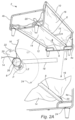
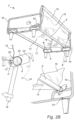
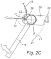
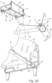
- Fig 2A-2D show a seating furniture support arrangement 6 according to the present inventive concept.
- the seating furniture support arrangement 6 is for a sofa 2, however, the arrangement is equally suitable for other pieces of seating furniture, such as an armchair.
- a sofa 2 comprises a frame comprising a first short-end section 4a, a second short-end section 4b and the support arrangement 6.
- the support arrangement 6 comprises a first longitudinal beam 8, a second longitudinal beam 12, and a third longitudinal beam 10 which carry the load of the seat and its occupant(s) to the short-end sections 4a, 4b.
- the first longitudinal beam 8, the second longitudinal beam 12 and the third longitudinal beam 10 may be provided in a kit and mounted to the first short-end section 4a and the second short-end section 4b at the site of use of the sofa. As depicted in Fig. 2A they are each mounted between the first short-end section 4a and the second short-end section 4b.
- a first elastic sheet 14 is attached to the first longitudinal beam 8 and the second longitudinal beam 12 and a second elastic sheet 16 is attached to the first longitudinal beam 8 and the third longitudinal beam 10.
- the second longitudinal beam 12 and the third longitudinal beam 10 are fixed with respect to the first short-end section 4a and the second short-end section 4b, while the first longitudinal beam 8 is pivotable, through plates 20, about a pivot axis running between a first pivot point P on the first short-end section 4a and a corresponding second pivot point on the second short-end section 4b.
- a lever 18, functioning as a handle, adapted to aid pivoting of the first longitudinal beam 8 is fixed to the first longitudinal beam 8 at a midpoint between the first short-end section 4a and the second short-end section 4b of the frame.
- Other locations for a lever or handle, as well at a different number of handles are equally possible, or no handle at all with an external force or torque provided through different means.
- the handle 8 or lever will be located on the stretching member.
- the handle is removable, for example by being screw-mountable on the first longitudinal beam 8.
- the lever 18 may be threaded as to be screw-mounted in a corresponding threaded bore in the first longitudinal beam 8 to be easily mountable before use and dismountable after use.
- the lever 18 may be foldable into or against the first longitudinal beam 8 after use.
- a cross-sectional view of the area close to the first pivot point P shows the longitudinal beam 8, the lever 18, the first sheet 14 and the second sheet 16.
- the sheets 14, 16 attach to the first longitudinal beam 8 at an attachment point 26 which is rotatable with respect to the longitudinal beam 8.
- the attachment point 26 is offset with respect to the pivot axis running between the first pivot point P and the second pivot point.
- an elastic sheet folds around the first longitudinal beam 8 forming a pocket, which is closed by a seam at the attachment point 26.
- the elastic sheet in the form of the pocket is rotatable with respect to the first longitudinal beam 8.
- the first elastic sheet 14 and the second elastic sheet 16 may be part of the same elastic sheet.
- a vertical, or close to vertical, plate 20 is fixed with respect to the first longitudinal beam 8 close to the first short-end section 4a of the frame.
- the plate has a slot 22 configured to interact with a stop on the first short-end section of the frame in the form of a pin 24.
- An identical plate 20 configured to interact with an identical tap (not visible) in the second short-end section 4b located close to the second short-end section 4b of the frame.
- the plates 20, and thereby the first longitudinal beam 8, are pivotable around the first pivot point P and the second pivot point (not visible) respectively.
- the first longitudinal beam 8, the lever 18, and the plates 20 provide a mechanism for, during assembly of the sofa, stretching the first elastic sheet 14 between the first longitudinal beam 8 and the second longitudinal beam 12, and further for stretching the second elastic sheet 16 between the first longitudinal beam 8 and the third longitudinal beam 10, where first longitudinal beam 8 functions as a stretching member for the elastic sheets, as will be described below.
- a circular arc L1 shows the path traveled by the slot 22 of the plate 20 when the first longitudinal beam 8 pivots around the pivot point P.
- a second circular arc L2 shows the path traveled by the center of the first longitudinal beam 8 during the same pivoting movement.
- FIG. 2B shows the same arrangement as in Fig. 2A during pivoting of the first longitudinal beam 8, the pivoting motion being driven by the application of an external force on the lever 18, as shown with large straight arrows.
- the distance between the attachment point 26 and the second longitudinal beam 12 will increase, thereby starting to stretch the first elastic sheet 14.
- the tension force of the first elastic sheet 14, shown with a large straight arrow next to the first elastic sheet 14 in the cross-sectional view, will counteract the pivoting movement, as its leverage with respect to the pivot point P is opposite to that of the externally applied force.
- the external force applied to the lever 18 will need to work against the tension force of the first elastic sheet 14.
- the tension force of the first elastic sheet 14 will cause the attachment point 26 to move around the first longitudinal beam 8 so that the stretched first elastic sheet 14 is perpendicular to the surface of the first longitudinal beam 8.
- the path followed by the attachment point 26, offset from the pivot point P, at this stage of pivoting will be determined by this condition.
- attachment point 26 may instead be fixed with respect to the first longitudinal beam 8 and the plates 20, i.e., to the stretching member.
- attachment point 26, offset from the pivot point P, will during pivoting follow a circular path similar to L1 or L2.
- the first longitudinal beam 8 has a circular cross-section.
- the longitudinal beam 8 may either be fixed with respect to the plates 20, resulting in an attachment point 26 fixed with respect to the plates 20, or be pivoted at the plates 20 at a point offset from the first pivot points P and the second pivot point.
- the mechanism is easy to operate even when having a high tension in the elastic sheets, providing good rigidity to the support.
- the elastic sheets 14, 16 need to be elastic enough to be able to be brought to the position of maximum tension.
- a large degree of elasticity is not required in the elastic sheets, i.e., their coefficient of elasticity, defined as the ratio of tension force to degree of stretching, may be rather high.
- a higher coefficient of elasticity allows for a high degree of tension of the sheet, giving rigid support for the seat och backrest.
- a latch (not shown) may be provided to prevent the first longitudinal beam 8 from sliding back from the final position, for example due to an externally applied force.
- the second elastic sheet 16 and the distance between the attachment point 26 and the third longitudinal beam 10 are arranged so that the second elastic sheet remains slack during the pivoting movement up to the position of maximum tension ( Fig. 2C ) of the first elastic sheet 14, only being stretched after that point.
- the external force works against the tension force of the first elastic sheet up to the position of maximum tension, with the second elastic sheet only being stretched with the pivoting having passed the position of maximum tension.
- the tension force of one of the first elastic sheet 14 helps to stretch the second elastic sheet 16 past the position of maximum tension, with the effect of less external force being needed to pivot the stretching member up to that point.
- the position of the attachment point 26, being rotatable around the first longitudinal beam 8 will be determined by the condition that the vector sum of the tension force of the first elastic sheet 14 and the tension force of the second elastic sheet 16 is perpendicular to the surface of the first elastic beam 8.
- both the first elastic sheet 14 and the second elastic sheet 16 are stretched simultaneously up to the position of maximum tension.
- the position of maximum tension will be defined based on the vector sum of the tension force of the first elastic sheet 14 and the tension force of the second elastic sheet 16.
- Fig. 4 shows an alternative embodiment, in a cross-sectional view, where the first longitudinal beam 8 is separate from the mechanism 28 for stretching the first elastic sheet 14 and fixed to the frame.
- the elastic sheet 14 runs between the second longitudinal beam (not shown) and the first longitudinal beam 8.
- the first elastic sheet 14 lies on top of the first longitudinal beam 8.
- the stretching mechanism 28 operates according to the same principle as described above in conjunction with Figs 2A-2D .
- the first elastic sheet 14 attached to a cylindrical structure similar to the first longitudinal beam depicted in Figs 2A-2D may in this embodiment be smaller, as it does not carry the load of, for example, an occupant of the sofa.
- all other structures may be identical to what was described above in conjunction with Figs 2A-2D .
- FIG. 3 shows the sofa 2 where the first elastic sheet 14 and the second elastic sheet 16 have been stretched according to the procedure described above.
- pillows 54 may be added, as indicated with arrows, to complete the sofa seats.
- pillows 52 may be added to complete the backrest.
Landscapes
- Life Sciences & Earth Sciences (AREA)
- Engineering & Computer Science (AREA)
- Wood Science & Technology (AREA)
- Chairs For Special Purposes, Such As Reclining Chairs (AREA)
- Chair Legs, Seat Parts, And Backrests (AREA)
Claims (9)
- Sitzmöbelträgeranordnung (6) für einen Sitz oder eine Rückenlehne,umfassend:
einen ersten (8) und einen zweiten (12) lasttragenden Längsträger,die jeweils an einem Sitzmöbelrahmen montierbar sind, der ein oder mehrere Teile umfasst, eine elastische Lage (16; 14) zum Bereitstellen einer Abstützung für einen von dem Sitz und der Rückenlehne, und einen Mechanismus zum Dehnen der elastischen Lage zwischen dem ersten Längsträger (8) und dem zweiten Längsträger (12),wobei der Mechanismus umfasst:
den ersten Längsträger (8), der an dem Rahmen um eine Schwenkachse schwenkbar ist, die elastische Lage (16; 14), die dann, wenn sich die Sitzmöbelträgeranordnung (6)in der installierten Position befindet, mit dem ersten Längsträger (8) versetzt zu der Schwenkachse verbunden ist, so dass der erste Längsträger (8) in Bezug auf den Rahmen als Reaktion auf eine Anwendung einer externen Kraft oder eines externen Drehmoments schwenkbar ist und die elastische Lage (16; 14) dehnt, wobei die externe Kraft oder das externe Drehmoment gegen die Spannkraft der elastischen Lage (16; 14) wirkt, bis ein Punkt maximaler Spannung erreicht ist, wobei über den Punkt der maximalen Spannung hinaus die Spannkraft ein weiteres Schwenken des ersten Längsträgers (8) erleichtert, so dass der erste Längsträger (8) in einer endgültigen Position an Ort und Stelle gehalten wird,dadurch gekennzeichnet, dass die elastische Lage (16; 14) eine erste elastische Lage ist, und die Sitzmöbelträgeranordnung (6) ferner umfasst:
einen dritten Längsträger (10); undeine zweite elastische Lage (16) zum Bereitstellen einer Abstützung für den anderen von dem Sitz und der Rückenlehne, wobei die zweite elastische Lage (16) auch mit dem ersten Längsträger (8) des Mechanismus verbunden ist, so dass das Schwenken des ersten Längsträgers den zweiten Längsträger (8) auch die zweite elastische Lage (16) zwischen dem ersten Längsträger (8) und dem dritten Längsträger (10) spannt, und wobei die externe Kraft oder das externe Drehmoment gegen die Spannkraft von einer der ersten elastischen Lage (14) und der zweiten elastischen Lage (16) bis zu dem Punkt der maximalen Spannung wirkt, wobei die andere der ersten elastischen Lage (14) und der zweiten elastischen Lage (16) nur mit dem Schwenken gedehnt wird, das den Punkt der maximalen Spannung passiert hat. - Sitzmöbelträgeranordnung (6) nach Anspruch 1, wobei die externe Kraft oder das externe Drehmoment gegen die Spannkräfte von sowohl der ersten elastischen Lage (14) als auch der zweiten elastischen Lage (16) bis zu dem Punkt der maximalen Spannung wirkt.
- Sitzmöbelträgeranordnung (6) nach Anspruch 1 oder 2, wobei die elastische Lage (16; 14), wenn die Sitzmöbelträgeranordnung (6) in der installierten Position ist, um den ersten Längsträger (8) gefaltet ist und eine Tasche bildet, wobei die Tasche vorzugsweise durch eine Naht (26) verschlossen ist.
- Sitzmöbelträgeranordnung nach einem der Ansprüche 1 bis 3, ferner umfassend einen Hebel (18) zum Anwenden der externen Kraft oder des externen Drehmoments, zum Schwenken des ersten Längsträgers (8), wobei der Hebel vorzugsweise entfernbar oder nach Gebrauch faltbar ist.
- Sitzmöbelträgeranordnung (6) nach einem der vorhergehenden Ansprüche, ferner umfassend einen Anschlag (24), wobei gegen den Anschlag (24) die Spannkraft der elastischen Lage (16; 14) durch den ersten Längsträger (8) wirkt, um den ersten Längsträger (8) in der endgültigen Position an Ort und Stelle zu verriegeln.
- Sitzmöbelträgeranordnung (6) nach einem der vorhergehenden Ansprüche, ferner umfassend einen Riegel, der ferner wirkt, um den ersten Längsträger (8) in der endgültigen Position an Ort und Stelle zu verriegeln.
- Sitzmöbelstück (2), umfassend die Sitzmöbelträgeranordnung (6) nach einem der vorhergehenden Ansprüche.
- Bausatz zum Zusammensetzen eines Sitzmöbelstücks, wobei der Bausatz Folgendes umfasst:
die Sitzmöbelträgeranordnung (6) nach einem der Ansprüche 1 bis 6. - Verfahren zum Zusammensetzen eines Sitzmöbelstücks, umfassend
die Sitzmöbelträgeranordnung (6) nach einem der Ansprüche 1 bis 6, wobei das Verfahren Folgendes umfasst:Bereitstellen:
eines Sitzmöbelrahmens in einem oder mehreren Teilen (4a, 4b), wobei der erste lasttragende Längsträger (8) und der zweite lasttragende Längsträger (12) jeweils an dem Sitzmöbelrahmen befestigt sind; undDehnen der elastischen Lage (16; 14) zwischen dem ersten Längsträger (8) und dem zweiten Längsträger (12), wobei das Dehnen der elastischen Lage (16; 14) umfasst:
Anwenden einer externen Kraft oder eines externen Drehmoments zum Schwenken des ersten Längsträgers um eine Schwenkachse in Bezug auf den ersten Rahmen, wobei die elastische Lage (16; 14) mit dem ersten Längsträger (8) versetzt zu der Schwenkachse verbunden ist, so dass das Schwenken die elastische Lage (16; 14) dehnt, wobei die externe Kraft oder das externe Drehmoment gegen die Spannkraft der elastischen Lage (16; 14) wirkt, bis ein Punkt maximaler Spannung erreicht ist, wobei die Spannkraft über den Punkt der maximalen Spannung hinaus das Schwenken des ersten Längsträgers (8) erleichtert und wirkt, um den ersten Längsträger (8) in der endgültigen Position an Ort und Stelle zu verriegeln.
Applications Claiming Priority (2)
| Application Number | Priority Date | Filing Date | Title |
|---|---|---|---|
| SE1751372 | 2017-11-06 | ||
| PCT/SE2018/051076 WO2019088894A1 (en) | 2017-11-06 | 2018-10-23 | Seating furniture support arrangement |
Publications (3)
| Publication Number | Publication Date |
|---|---|
| EP3706601A1 EP3706601A1 (de) | 2020-09-16 |
| EP3706601A4 EP3706601A4 (de) | 2021-08-18 |
| EP3706601B1 true EP3706601B1 (de) | 2024-12-25 |
Family
ID=66333237
Family Applications (1)
| Application Number | Title | Priority Date | Filing Date |
|---|---|---|---|
| EP18873018.8A Active EP3706601B1 (de) | 2017-11-06 | 2018-10-23 | Sitzmöbelträgeranordnung |
Country Status (4)
| Country | Link |
|---|---|
| US (1) | US11160389B2 (de) |
| EP (1) | EP3706601B1 (de) |
| CN (1) | CN111295114B (de) |
| WO (1) | WO2019088894A1 (de) |
Families Citing this family (4)
| Publication number | Priority date | Publication date | Assignee | Title |
|---|---|---|---|---|
| CN112056846B (zh) * | 2020-06-19 | 2022-06-17 | 永艺家具股份有限公司 | 一种坐具的支撑装置及其安装方法 |
| CN113317652B (zh) * | 2021-05-29 | 2023-02-28 | 杭州龙神工贸有限公司 | 一种沙发 |
| CN117860071A (zh) * | 2024-02-05 | 2024-04-12 | 傲基科技股份有限公司 | 沙发 |
| US12446553B2 (en) | 2024-03-05 | 2025-10-21 | Fujian Fuhele Supply Chain Co., Ltd. | Tower furniture for pet animal |
Family Cites Families (24)
| Publication number | Priority date | Publication date | Assignee | Title |
|---|---|---|---|---|
| US1933040A (en) | 1930-08-18 | 1933-10-31 | Kalamazoo Sled Company | Folding chair |
| US2635550A (en) * | 1949-10-03 | 1953-04-21 | Albert J Granberg | Manually portable crankcase drain pump assembly |
| US3273877A (en) * | 1965-04-26 | 1966-09-20 | Gen Motors Corp | Seat structure |
| US3645550A (en) | 1969-10-15 | 1972-02-29 | Sahn Inc | Furniture construction |
| US3698766A (en) * | 1969-11-10 | 1972-10-17 | Martin Borenstein | Sling type upholstered furniture |
| US3985460A (en) * | 1975-10-22 | 1976-10-12 | Peter Piper Plastics, Inc. | Frame seat and mechanism for joining frame portions thereof |
| JPS5552854Y2 (de) | 1977-09-09 | 1980-12-08 | ||
| US4232899A (en) * | 1979-06-04 | 1980-11-11 | August Incorporated | Seating unit and method of construction |
| US4828324A (en) * | 1983-11-21 | 1989-05-09 | Putnam Monroe P | Knockdown upholstered furniture construction |
| US6604792B1 (en) * | 2000-11-07 | 2003-08-12 | Franklin Products, Inc. | Seat assembly and apparatus for releasably retaining a diaphragm to be used as a seat |
| US20020145320A1 (en) * | 2001-04-09 | 2002-10-10 | Bernhard Zeiler | Futon furniture frame having a single panel of elastomeric support fabric |
| US6854805B2 (en) * | 2002-03-27 | 2005-02-15 | Delta Tooling Co., Ltd. | Seat structure |
| JP4243669B2 (ja) * | 2002-03-27 | 2009-03-25 | 株式会社デルタツーリング | 座席構造 |
| JP4323427B2 (ja) * | 2002-09-03 | 2009-09-02 | 株式会社豊田中央研究所 | シート |
| JP4081347B2 (ja) * | 2002-10-28 | 2008-04-23 | 株式会社デルタツーリング | 座席構造 |
| JP4634761B2 (ja) * | 2004-08-26 | 2011-02-16 | 株式会社デルタツーリング | シート |
| US20060214476A1 (en) * | 2005-03-24 | 2006-09-28 | Rojas Robert R | Adjustable configuration seating |
| JP4554444B2 (ja) * | 2005-06-13 | 2010-09-29 | 株式会社デルタツーリング | 座席構造 |
| DE102009043009A1 (de) * | 2009-08-31 | 2011-03-03 | Thomas Beteiligungs- und Vermögens-GmbH & Co. KG | Unterfederung sowie Schlaf-, Sitz- oder Liegemöbel mit Unterfederung |
| US20110198909A1 (en) * | 2010-02-16 | 2011-08-18 | Jason Fickas Fifield | Suspended pin chair |
| DE102010014985A1 (de) * | 2010-04-14 | 2011-10-20 | Daimler Ag | Kraftfahrzeug mit einer variablen Sitzlehne |
| DE102010055994A1 (de) * | 2010-12-23 | 2012-06-28 | Airbus Operations Gmbh | Liege- oder Sitzvorrichtung |
| JP6154907B2 (ja) * | 2013-09-30 | 2017-06-28 | ジョンソン コントロールズ テクノロジー カンパニーJohnson Controls Technology Company | 座席 |
| DE102014207972A1 (de) * | 2014-04-28 | 2015-10-29 | Kintec-Solution Gmbh | Sitzmöbelstück und Beschlag hierfür |
-
2018
- 2018-10-23 WO PCT/SE2018/051076 patent/WO2019088894A1/en not_active Ceased
- 2018-10-23 CN CN201880071247.9A patent/CN111295114B/zh active Active
- 2018-10-23 US US16/760,924 patent/US11160389B2/en active Active
- 2018-10-23 EP EP18873018.8A patent/EP3706601B1/de active Active
Also Published As
| Publication number | Publication date |
|---|---|
| US20210169235A1 (en) | 2021-06-10 |
| EP3706601A4 (de) | 2021-08-18 |
| CN111295114B (zh) | 2023-07-14 |
| WO2019088894A1 (en) | 2019-05-09 |
| US11160389B2 (en) | 2021-11-02 |
| EP3706601A1 (de) | 2020-09-16 |
| CN111295114A (zh) | 2020-06-16 |
Similar Documents
| Publication | Publication Date | Title |
|---|---|---|
| US11160389B2 (en) | Seating furniture support arrangement | |
| US10820708B2 (en) | Furniture member with wall-proximity mechanism and locking trigger | |
| US7293833B2 (en) | Chair and support mechanism unit thereof | |
| KR100336010B1 (ko) | 가변정점을구비한등부지지체 | |
| US6334651B1 (en) | Lumbar support adjusting mechanism | |
| EP3773078B1 (de) | Sitzmöbelträgeranordnung | |
| AU2014283918B2 (en) | Stroller | |
| CN106028873B (zh) | 家具配件、具有两个家具配件的结构以及家具配件的用途 | |
| ATE552754T1 (de) | Stützanordnung und entsprechende sitzstruktur | |
| US10842273B2 (en) | Mechanical linkage structure for linking chair and seat, frame and chair having the mechanical linkage structure | |
| US20170251817A1 (en) | System and method for raising a bed off the floor | |
| JP2002540876A (ja) | 一体型調節可能なシートバスケット | |
| US20160037933A1 (en) | Futon frames including a fixed pivot point | |
| US5584532A (en) | Convertible seats with variable dimensions for means of public transportation, and a convertible structure with variable dimensions comprising said seats | |
| US7377583B1 (en) | Folding chair | |
| WO2004038254A1 (en) | Transmission amplifier assembly for a bowden cable and method of using the same | |
| JPH0622827A (ja) | リクライニングシートメカニズム | |
| KR20170076211A (ko) | 시트의 폴딩 장치 | |
| JPWO2016038671A1 (ja) | 折り畳み可能な車椅子 | |
| TW200836672A (en) | Backrest for a chair, and chair comprising the same | |
| DE202021105091U1 (de) | Einbauhandschalter | |
| CN206155234U (zh) | 座椅角度调节装置 | |
| CN217937645U (zh) | 一种座椅支架结构及座椅 | |
| CN110965869A (zh) | 一种外开手柄总成装配组件 | |
| CN201061373Y (zh) | 一种活动集成搁腿 |
Legal Events
| Date | Code | Title | Description |
|---|---|---|---|
| STAA | Information on the status of an ep patent application or granted ep patent |
Free format text: STATUS: THE INTERNATIONAL PUBLICATION HAS BEEN MADE |
|
| PUAI | Public reference made under article 153(3) epc to a published international application that has entered the european phase |
Free format text: ORIGINAL CODE: 0009012 |
|
| STAA | Information on the status of an ep patent application or granted ep patent |
Free format text: STATUS: REQUEST FOR EXAMINATION WAS MADE |
|
| 17P | Request for examination filed |
Effective date: 20200325 |
|
| AK | Designated contracting states |
Kind code of ref document: A1 Designated state(s): AL AT BE BG CH CY CZ DE DK EE ES FI FR GB GR HR HU IE IS IT LI LT LU LV MC MK MT NL NO PL PT RO RS SE SI SK SM TR |
|
| AX | Request for extension of the european patent |
Extension state: BA ME |
|
| DAV | Request for validation of the european patent (deleted) | ||
| DAX | Request for extension of the european patent (deleted) | ||
| REG | Reference to a national code |
Ref legal event code: R079 Ipc: A47C0007280000 Ref country code: DE Ref legal event code: R079 Ref document number: 602018078011 Country of ref document: DE Free format text: PREVIOUS MAIN CLASS: A47C0017040000 Ipc: A47C0007280000 |
|
| A4 | Supplementary search report drawn up and despatched |
Effective date: 20210719 |
|
| RIC1 | Information provided on ipc code assigned before grant |
Ipc: A47C 7/28 20060101AFI20210713BHEP Ipc: A47C 4/02 20060101ALI20210713BHEP Ipc: A47C 5/06 20060101ALI20210713BHEP Ipc: A47C 31/02 20060101ALI20210713BHEP |
|
| RIN1 | Information on inventor provided before grant (corrected) |
Inventor name: SVENSSON, SEBASTIAN |
|
| STAA | Information on the status of an ep patent application or granted ep patent |
Free format text: STATUS: EXAMINATION IS IN PROGRESS |
|
| 17Q | First examination report despatched |
Effective date: 20230425 |
|
| GRAP | Despatch of communication of intention to grant a patent |
Free format text: ORIGINAL CODE: EPIDOSNIGR1 |
|
| STAA | Information on the status of an ep patent application or granted ep patent |
Free format text: STATUS: GRANT OF PATENT IS INTENDED |
|
| INTG | Intention to grant announced |
Effective date: 20240405 |
|
| RAP1 | Party data changed (applicant data changed or rights of an application transferred) |
Owner name: INTER IKEA SYSTEMS B.V. |
|
| GRAJ | Information related to disapproval of communication of intention to grant by the applicant or resumption of examination proceedings by the epo deleted |
Free format text: ORIGINAL CODE: EPIDOSDIGR1 |
|
| STAA | Information on the status of an ep patent application or granted ep patent |
Free format text: STATUS: EXAMINATION IS IN PROGRESS |
|
| GRAP | Despatch of communication of intention to grant a patent |
Free format text: ORIGINAL CODE: EPIDOSNIGR1 |
|
| STAA | Information on the status of an ep patent application or granted ep patent |
Free format text: STATUS: GRANT OF PATENT IS INTENDED |
|
| INTC | Intention to grant announced (deleted) | ||
| INTG | Intention to grant announced |
Effective date: 20240807 |
|
| GRAS | Grant fee paid |
Free format text: ORIGINAL CODE: EPIDOSNIGR3 |
|
| GRAA | (expected) grant |
Free format text: ORIGINAL CODE: 0009210 |
|
| STAA | Information on the status of an ep patent application or granted ep patent |
Free format text: STATUS: THE PATENT HAS BEEN GRANTED |
|
| AK | Designated contracting states |
Kind code of ref document: B1 Designated state(s): AL AT BE BG CH CY CZ DE DK EE ES FI FR GB GR HR HU IE IS IT LI LT LU LV MC MK MT NL NO PL PT RO RS SE SI SK SM TR |
|
| REG | Reference to a national code |
Ref country code: GB Ref legal event code: FG4D |
|
| REG | Reference to a national code |
Ref country code: CH Ref legal event code: EP |
|
| REG | Reference to a national code |
Ref country code: DE Ref legal event code: R096 Ref document number: 602018078011 Country of ref document: DE |
|
| REG | Reference to a national code |
Ref country code: IE Ref legal event code: FG4D |
|
| REG | Reference to a national code |
Ref country code: LT Ref legal event code: MG9D |
|
| PG25 | Lapsed in a contracting state [announced via postgrant information from national office to epo] |
Ref country code: HR Free format text: LAPSE BECAUSE OF FAILURE TO SUBMIT A TRANSLATION OF THE DESCRIPTION OR TO PAY THE FEE WITHIN THE PRESCRIBED TIME-LIMIT Effective date: 20241225 |
|
| PG25 | Lapsed in a contracting state [announced via postgrant information from national office to epo] |
Ref country code: FI Free format text: LAPSE BECAUSE OF FAILURE TO SUBMIT A TRANSLATION OF THE DESCRIPTION OR TO PAY THE FEE WITHIN THE PRESCRIBED TIME-LIMIT Effective date: 20241225 |
|
| PG25 | Lapsed in a contracting state [announced via postgrant information from national office to epo] |
Ref country code: BG Free format text: LAPSE BECAUSE OF FAILURE TO SUBMIT A TRANSLATION OF THE DESCRIPTION OR TO PAY THE FEE WITHIN THE PRESCRIBED TIME-LIMIT Effective date: 20241225 |
|
| PG25 | Lapsed in a contracting state [announced via postgrant information from national office to epo] |
Ref country code: NO Free format text: LAPSE BECAUSE OF FAILURE TO SUBMIT A TRANSLATION OF THE DESCRIPTION OR TO PAY THE FEE WITHIN THE PRESCRIBED TIME-LIMIT Effective date: 20250325 |
|
| PG25 | Lapsed in a contracting state [announced via postgrant information from national office to epo] |
Ref country code: LV Free format text: LAPSE BECAUSE OF FAILURE TO SUBMIT A TRANSLATION OF THE DESCRIPTION OR TO PAY THE FEE WITHIN THE PRESCRIBED TIME-LIMIT Effective date: 20241225 Ref country code: GR Free format text: LAPSE BECAUSE OF FAILURE TO SUBMIT A TRANSLATION OF THE DESCRIPTION OR TO PAY THE FEE WITHIN THE PRESCRIBED TIME-LIMIT Effective date: 20250326 |
|
| PG25 | Lapsed in a contracting state [announced via postgrant information from national office to epo] |
Ref country code: RS Free format text: LAPSE BECAUSE OF FAILURE TO SUBMIT A TRANSLATION OF THE DESCRIPTION OR TO PAY THE FEE WITHIN THE PRESCRIBED TIME-LIMIT Effective date: 20250325 |
|
| REG | Reference to a national code |
Ref country code: NL Ref legal event code: MP Effective date: 20241225 |
|
| PG25 | Lapsed in a contracting state [announced via postgrant information from national office to epo] |
Ref country code: NL Free format text: LAPSE BECAUSE OF FAILURE TO SUBMIT A TRANSLATION OF THE DESCRIPTION OR TO PAY THE FEE WITHIN THE PRESCRIBED TIME-LIMIT Effective date: 20241225 |
|
| REG | Reference to a national code |
Ref country code: AT Ref legal event code: MK05 Ref document number: 1753433 Country of ref document: AT Kind code of ref document: T Effective date: 20241225 |
|
| PG25 | Lapsed in a contracting state [announced via postgrant information from national office to epo] |
Ref country code: SM Free format text: LAPSE BECAUSE OF FAILURE TO SUBMIT A TRANSLATION OF THE DESCRIPTION OR TO PAY THE FEE WITHIN THE PRESCRIBED TIME-LIMIT Effective date: 20241225 |
|
| PG25 | Lapsed in a contracting state [announced via postgrant information from national office to epo] |
Ref country code: PL Free format text: LAPSE BECAUSE OF FAILURE TO SUBMIT A TRANSLATION OF THE DESCRIPTION OR TO PAY THE FEE WITHIN THE PRESCRIBED TIME-LIMIT Effective date: 20241225 |
|
| PG25 | Lapsed in a contracting state [announced via postgrant information from national office to epo] |
Ref country code: ES Free format text: LAPSE BECAUSE OF FAILURE TO SUBMIT A TRANSLATION OF THE DESCRIPTION OR TO PAY THE FEE WITHIN THE PRESCRIBED TIME-LIMIT Effective date: 20241225 |
|
| PG25 | Lapsed in a contracting state [announced via postgrant information from national office to epo] |
Ref country code: IS Free format text: LAPSE BECAUSE OF FAILURE TO SUBMIT A TRANSLATION OF THE DESCRIPTION OR TO PAY THE FEE WITHIN THE PRESCRIBED TIME-LIMIT Effective date: 20250425 |
|
| PG25 | Lapsed in a contracting state [announced via postgrant information from national office to epo] |
Ref country code: PT Free format text: LAPSE BECAUSE OF FAILURE TO SUBMIT A TRANSLATION OF THE DESCRIPTION OR TO PAY THE FEE WITHIN THE PRESCRIBED TIME-LIMIT Effective date: 20250428 |
|
| PG25 | Lapsed in a contracting state [announced via postgrant information from national office to epo] |
Ref country code: EE Free format text: LAPSE BECAUSE OF FAILURE TO SUBMIT A TRANSLATION OF THE DESCRIPTION OR TO PAY THE FEE WITHIN THE PRESCRIBED TIME-LIMIT Effective date: 20241225 |
|
| PG25 | Lapsed in a contracting state [announced via postgrant information from national office to epo] |
Ref country code: AT Free format text: LAPSE BECAUSE OF FAILURE TO SUBMIT A TRANSLATION OF THE DESCRIPTION OR TO PAY THE FEE WITHIN THE PRESCRIBED TIME-LIMIT Effective date: 20241225 Ref country code: RO Free format text: LAPSE BECAUSE OF FAILURE TO SUBMIT A TRANSLATION OF THE DESCRIPTION OR TO PAY THE FEE WITHIN THE PRESCRIBED TIME-LIMIT Effective date: 20241225 |
|
| PG25 | Lapsed in a contracting state [announced via postgrant information from national office to epo] |
Ref country code: SK Free format text: LAPSE BECAUSE OF FAILURE TO SUBMIT A TRANSLATION OF THE DESCRIPTION OR TO PAY THE FEE WITHIN THE PRESCRIBED TIME-LIMIT Effective date: 20241225 |
|
| PG25 | Lapsed in a contracting state [announced via postgrant information from national office to epo] |
Ref country code: CZ Free format text: LAPSE BECAUSE OF FAILURE TO SUBMIT A TRANSLATION OF THE DESCRIPTION OR TO PAY THE FEE WITHIN THE PRESCRIBED TIME-LIMIT Effective date: 20241225 |
|
| PG25 | Lapsed in a contracting state [announced via postgrant information from national office to epo] |
Ref country code: IT Free format text: LAPSE BECAUSE OF FAILURE TO SUBMIT A TRANSLATION OF THE DESCRIPTION OR TO PAY THE FEE WITHIN THE PRESCRIBED TIME-LIMIT Effective date: 20241225 |
|
| PG25 | Lapsed in a contracting state [announced via postgrant information from national office to epo] |
Ref country code: SE Free format text: LAPSE BECAUSE OF FAILURE TO SUBMIT A TRANSLATION OF THE DESCRIPTION OR TO PAY THE FEE WITHIN THE PRESCRIBED TIME-LIMIT Effective date: 20241225 |
|
| REG | Reference to a national code |
Ref country code: DE Ref legal event code: R097 Ref document number: 602018078011 Country of ref document: DE |
|
| PG25 | Lapsed in a contracting state [announced via postgrant information from national office to epo] |
Ref country code: DK Free format text: LAPSE BECAUSE OF FAILURE TO SUBMIT A TRANSLATION OF THE DESCRIPTION OR TO PAY THE FEE WITHIN THE PRESCRIBED TIME-LIMIT Effective date: 20241225 |
|
| PLBE | No opposition filed within time limit |
Free format text: ORIGINAL CODE: 0009261 |
|
| STAA | Information on the status of an ep patent application or granted ep patent |
Free format text: STATUS: NO OPPOSITION FILED WITHIN TIME LIMIT |
|
| 26N | No opposition filed |
Effective date: 20250926 |
|
| PGFP | Annual fee paid to national office [announced via postgrant information from national office to epo] |
Ref country code: DE Payment date: 20251028 Year of fee payment: 8 |