EP3705653B1 - Halterung für ein becken für eine wandmontage - Google Patents
Halterung für ein becken für eine wandmontage Download PDFInfo
- Publication number
- EP3705653B1 EP3705653B1 EP20158368.9A EP20158368A EP3705653B1 EP 3705653 B1 EP3705653 B1 EP 3705653B1 EP 20158368 A EP20158368 A EP 20158368A EP 3705653 B1 EP3705653 B1 EP 3705653B1
- Authority
- EP
- European Patent Office
- Prior art keywords
- wall
- bowl
- inlet pipe
- section
- pipe
- Prior art date
- Legal status (The legal status is an assumption and is not a legal conclusion. Google has not performed a legal analysis and makes no representation as to the accuracy of the status listed.)
- Active
Links
Images


Classifications
-
- E—FIXED CONSTRUCTIONS
- E03—WATER SUPPLY; SEWERAGE
- E03D—WATER-CLOSETS OR URINALS WITH FLUSHING DEVICES; FLUSHING VALVES THEREFOR
- E03D11/00—Other component parts of water-closets, e.g. noise-reducing means in the flushing system, flushing pipes mounted in the bowl, seals for the bowl outlet, devices preventing overflow of the bowl contents; devices forming a water seal in the bowl after flushing, devices eliminating obstructions in the bowl outlet or preventing backflow of water and excrements from the waterpipe
- E03D11/13—Parts or details of bowls; Special adaptations of pipe joints or couplings for use with bowls, e.g. provisions in bowl construction preventing backflow of waste-water from the bowl in the flushing pipe or cistern, provisions for a secondary flushing, for noise-reducing
- E03D11/135—Supports for bowls
-
- E—FIXED CONSTRUCTIONS
- E03—WATER SUPPLY; SEWERAGE
- E03C—DOMESTIC PLUMBING INSTALLATIONS FOR FRESH WATER OR WASTE WATER; SINKS
- E03C1/00—Domestic plumbing installations for fresh water or waste water; Sinks
- E03C1/12—Plumbing installations for waste water; Basins or fountains connected thereto; Sinks
- E03C1/32—Holders or supports for basins
- E03C1/322—Holders or supports for basins connected to the wall only
- E03C1/324—Holders or supports for basins connected to the wall only adjustable
-
- E—FIXED CONSTRUCTIONS
- E03—WATER SUPPLY; SEWERAGE
- E03D—WATER-CLOSETS OR URINALS WITH FLUSHING DEVICES; FLUSHING VALVES THEREFOR
- E03D11/00—Other component parts of water-closets, e.g. noise-reducing means in the flushing system, flushing pipes mounted in the bowl, seals for the bowl outlet, devices preventing overflow of the bowl contents; devices forming a water seal in the bowl after flushing, devices eliminating obstructions in the bowl outlet or preventing backflow of water and excrements from the waterpipe
- E03D11/13—Parts or details of bowls; Special adaptations of pipe joints or couplings for use with bowls, e.g. provisions in bowl construction preventing backflow of waste-water from the bowl in the flushing pipe or cistern, provisions for a secondary flushing, for noise-reducing
- E03D11/14—Means for connecting the bowl to the wall, e.g. to a wall outlet
Definitions
- the invention relates to a holder for a basin for wall mounting according to the preamble of claim 1.
- the basins are preferably toilet bowls or urinals.
- the basins can also be basins for other uses.
- the invention is described below using a toilet bowl, but without intending to impose any restrictions thereto.
- Toilet bowls are mounted on walls without any part of the bowl being in contact with the floor. To do this, two support rods, preferably threaded rods, are initially provided on the wall, as well as wall connections for the inlet of flush water and for the outlet of waste water. The vertical and horizontal distances between these four mounting contacts are standardized, so that different toilet bowls can be mounted on different pre-wall installation units from different manufacturers.
- the height of the toilet bowl to be installed must usually be determined before installing the wall-mounted installation. Subsequent vertical adjustment of the position of the bowl is then not possible or only possible with a high level of installation effort.
- the state of the art includes a variably adjustable installation mechanism that is directly connected to the toilet bowl and allows vertical adjustment of the installation position within specified limits.
- this requires a specially designed toilet bowl that provides space for such an installation mechanism.
- the WO 2018/055415 A discloses a mounting arrangement for movably mounting a toilet bowl.
- the arrangement comprises a fixed mounting portion and a movable mounting bracket for receiving the toilet bowl.
- Movable fluid connections are provided to movably connect the toilet bowl to a fixed fluid source and a fixed drain opening.
- space-saving bathroom installations are disclosed in which a toilet bowl can be mounted such that it can be moved from a stowed position to an extended position and vice versa using a rotary movement.
- the WO 2011/083396 A discloses a support structure for supporting a sanitary fitting, comprising two upright fastening profiles provided with openings for fastening to a wall, and two cross-beam elements which connect the two fastening profiles to each other.
- connection device for a toilet bowl comprising a support arrangement that can be displaceably connected to the toilet bowl, with a first bearing point in which a flush pipe is mounted, and with a second bearing point in which an outlet pipe is mounted.
- the axial distance between the center axis of the flush pipe and the center axis of the outlet pipe in the support arrangement is fixed.
- the support arrangement and the toilet bowl can be displaced relative to one another in the direction of an adjustment movement when adjusting the height of the toilet bowl.
- the flush pipe and the outlet pipe each have at least one compensation section, with which an adjustment offset resulting from the adjustment movement between the support arrangement and the toilet bowl between the flush pipe mounted in the support arrangement and the outlet pipe mounted in the support arrangement and the flush water inlet or waste water outlet arranged on the toilet bowl side can be compensated.
- connection mechanism that allows the height of a suspended toilet bowl to be adjusted according to the user's preferences and needs.
- the connection mechanism comprises a bracket that allows the toilet bowl to be installed on the surface of a wall using connection elements of the toilet bowl without the need for any modification to the wall.
- the DE 299 14 404 U shows a height-adjustable washbasin that is attached to support strips that are guided vertically on guide strips, with the guide strips being attached to a room wall.
- the support strips each have a rack-like section to which a gear and a drive motor that can be operated by means of a switch are assigned.
- the DE 10 2013 001 798 A shows a support device for a toilet bowl, with a first carrier which has first fastening elements for statically mounting the first carrier on a structure and second fastening elements for attaching a cistern to the first carrier, and with a second carrier which has third fastening elements for attaching the toilet bowl to the second carrier, wherein the second carrier is slidably connected to the first carrier between a first, upper position and a second, lower position spaced therefrom in the direction of gravity, wherein the second carrier can be locked at least in the first, upper position and in the second, lower position.
- a spring which acts against the direction of gravity, one end of which is connected to the first carrier and the other end of which is connected to the second carrier.
- the present invention is based on the technical problem of providing a variably usable holder for a basin, in particular a toilet bowl or urinal, for wall mounting.
- the holder according to the invention comprises a frame, an inlet pipe which has a wall-side connection and a basin-side connection, a drain pipe which has a wall-side connection and a basin-side connection, fastening openings for receiving support rods pre-assembled on the wall, for example fastened in the wall and/or in an installation element, and fastening elements, in particular designed as threaded rods, for fastening the basin to the frame, wherein the inlet pipe can be connected to an inlet installed in a wall and to an inlet of the basin, wherein the drain pipe can be connected to an outlet installed in the wall and to an outlet of the basin, wherein the fastening openings are designed to enable variable wall mounting of the frame in at least two different vertical positions with support rods pre-assembled on the wall and wherein the wall-side connections of the inlet pipe and the drain pipe are vertically adjustable relative to the basin-side connections of the inlet pipe and the drain pipe, and is characterized in that the inlet pipe and the drain pipe have a have
- the vertical and horizontal distances of the basin-side connections and the two fastening elements correspond to the standardized distances, so that any basin, in particular a toilet bowl or urinal, can be attached to the bracket on the basin side.
- the vertical and horizontal distances of the wall-side connections and the fastening openings in at least two different vertical positions of the bracket relative to the wall mounting position, correspond to the standardized distances between the support rods, inlet and outlet pre-assembled on the wall and/or in an installation element.
- a basin in particular a toilet bowl or urinal, can be mounted on the wall in at least two different vertical positions using the bracket.
- the model of the basin is not important, as the basin-side connections and fastenings have standardized distances.
- the design according to the invention consists in that the inlet pipe and the outlet pipe have a stepped course, each with a wall section, a basin section and an angle section running obliquely between the wall section and the basin section, wherein the respective angle section is formed from separate parts which run at an angle to one another, that the angle sections are divided into two parts, wherein one part of the angle sections is connected to the wall section and one part of the angle sections is connected to the basin section in a rotationally fixed manner, that a rotatable flange connection connects the separate parts of the respective angle section rotatably connected to one another and that the inlet pipe and the outlet pipe can each be adjusted by rotating about an axis parallel to the axis of the wall-side connections and the basin-side connections.
- a gear can be provided for rotating the inlet pipe and the outlet pipe together.
- the gear has a rack connected to the frame and the inlet pipe and the outlet pipe are connected to a gear wheel forming at least one pitch circle. If the frame is raised while the wall-side connections of the inlet pipe and the outlet pipe are connected, the angle sections of the inlet pipe and the outlet pipe rotate against each other and enable a relative displacement of the wall-side and basin-side connections against each other.
- a further improvement of the transmission is achieved by providing the frame with a first mechanism on the wall side and the first mechanism has receiving openings for receiving the wall-side support rods and receiving openings for receiving the inlet pipe and the drain pipe. Furthermore, the frame can be provided with a second mechanism on the basin side and the second mechanism can carry the basin-side fastening elements and have receiving openings for receiving the wall-side support rods and the inlet pipe and the drain pipe.
- the two Mimics basically cause the inlet pipe and the outlet pipe as well as the fastening elements to be positioned relative to each other on both the wall and the basin side.
- the receiving openings for the inlet pipe and the outlet pipe have an inner diameter that is slightly larger than the respective outer diameter of the two pipes. The resulting gap allows the two pipes to be mobile relative to the respective facial expressions.
- the receiving openings of the first and second mimics for the inlet pipe and the drain pipe each provide a support for the pipes on the wall side and on the basin side during the movement caused by raising or lowering the frame.
- the support automatically causes the angle sections of the inlet pipe and the drain pipe to twist in the plane of the rotating flange connection and the vertical adjustment takes place without the need for manual readjustment.
- the fastening openings can be slot-shaped and extend vertically.
- the two pre-assembled support rods or threaded rods are first positioned vertically in the fastening openings and then fixed.
- the basin can then be attached to the support in the vertically adjusted position.
- the mounting holes can consist of at least two holes arranged vertically one above the other. This provides a grid of holes that does not allow the bracket to be positioned vertically on the wall, but does make it easier to fix the position.
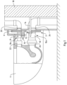
- a first embodiment of a holder 2 for a toilet bowl 4 for wall mounting is shown.
- the holder 2 has a frame 6 which has a predetermined horizontal construction depth which is required for the subsequent construction of the vertically adjustable elements.
- the frame 6 has an inlet pipe 8 and an outlet pipe 10 as well as two fastening openings 12 for receiving wall-mounted support rods 14. Furthermore, two fastening elements in the form of threaded rods 16 are provided for fastening the toilet bowl 4 to the frame 6.
- the inlet pipe 8 is connected to an inlet 20 installed in a wall 18 and to an inlet 22 of the basin 4 and the drain pipe 10 is connected to an outlet 24 installed in the wall 18 and to an outlet 26 of the basin 4.
- the fastening openings 12 are further designed in such a way that wall mounting of the bracket 6 and thus of the toilet bowl 4 is possible in at least two different vertical positions, which is possible in the two Fig. 1 and 2 is shown.
- the wall-side connections of the inlet pipe 8 and the outlet pipe 10 are vertically adjustable relative to the bowl-side connections of the inlet pipe 8 and the outlet pipe 10. This achieves the variability of the vertical position of the toilet bowl 4 relative to the wall.
- the Fig. 1 and 2 In the embodiment shown, at least one flexible hose section 8a and 10a is provided between the wall-side connections and the basin-side connections of the inlet pipe 8 and the outlet pipe 10. This allows the function of the holder 2 and the vertical replacement to be implemented steplessly.
- the fastening openings 12 are slot-shaped and extend vertically. This allows the support rods 14 to be positioned at different points in the vertical direction. This allows the entire support 2 to be positioned at different positions in the vertical direction and the toilet bowl can be set up vertically in its mounted position.
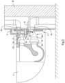
- Fig. 1 a highest vertical positioning of the toilet bowl 4 and Fig. 2 a lowest positioning.
- Fig. 1a and 2a show an embodiment modified from the previous embodiment, wherein the same components are identified by the same reference numerals.
- Fig. 1a are in the starting position shown - in contrast to the Fig. 1 - the support rods 14 are arranged at the upper - and not at the lower - end of the fastening openings 12.
- the support rods 14 are located at the lower end of the fastening openings 12, in contrast to the Fig. 2 , in which the stop at the upper end is shown.
- Fig. 2a The position shown results in the drain pipe 10 running downwards from the toilet bowl 4, while in Fig. 2d an ascent can be seen.
- the arrangement according to Fig. 2a has the advantage that the water level inside the toilet bowl does not increase when the toilet bowl is in the Fig. 2a
- the position shown in Fig. 2 In the position shown, however, the water level inside the toilet bowl rises.
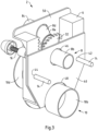
- FIG. 3 to 6 An embodiment of a holder 2 according to the invention is shown, wherein the same reference numerals designate the same components as in the Fig. 1 and 2
- the bracket 2 is in the Fig. 3 to 6 without wall installation (except for the support bars 14) and without a mounted toilet bowl.
- the inlet pipe 8 and the outlet pipe 10 have a stepped course, each with a wall section 8b, 10b, a basin section 8c, 10c and an angle section 8d, 10d running obliquely between the wall section 8b, 10b and the basin section 8c, 10c.
- the angle sections 8d, 10d are divided into two parts, with one part of the angle sections 8d, 10d being connected to the wall section 8b, 10b and one part of the angle sections 8d, 10d being connected to the Basin section 8c, 10c is connected in a rotationally fixed manner.
- a rotatable flange connection 8e, 10e connects the separate parts of the angle sections 8d, 10d:
- the plane of the flange connection 8e, 10e runs essentially perpendicular to the axes of the wall sections 8b, 10b and the basin section 8c, 10c.
- the inlet pipe 8 and the outlet pipe 10 can thus be adjusted by rotating them about an axis parallel to the axis of the wall-side connections and the basin-side connections.
- a gear is provided for the joint rotation of the inlet pipe 8 and the outlet pipe 10.
- the gear has a rack 30 connected to the frame 6 and the inlet pipe 8 and the outlet pipe 10 are connected to a gear 32, 34 forming at least one pitch circle.
- the gears 32, 34 are connected to the rack 30 and are driven to a rotary movement by this engagement when the frame 6 is raised or lowered.
- the rotary movement adjusts the vertical positions of the wall-side connections and the basin-side connections of the inlet pipe 8 and the outlet pipe 10 relative to each other. If the wall-side connections are connected to the (for example in the Fig. 1 and 2 shown) wall-side inlet 20 and the wall-side drain 24, the basin-side connections of the inlet pipe 8 and the drain pipe 10 move vertically up or down.
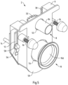
- the Fig. 3 to 5 show a lower or low positioning of the basin-side connections in relation to the wall-side connections.
- the two parts of the angle sections 8d, 10d run essentially in a straight line to each other.
- the wall sections 8b, 10b and the basin sections 8c, 10c must each be rotated in opposite directions by 90° or 180°.
- the frame 6 is provided with a first mimic 40 on the wall side and that the first mimic 40 has receiving openings 42, 44 for receiving the wall-side support rods 14 and receiving openings 46 and 48 for receiving the inlet pipe 8 and the drain pipe 10.
- the receiving openings 42, 44 are adapted to the diameter of the support rods 14, while the receiving openings 46 and 48 are each slightly larger than the corresponding outer diameters of the inlet pipe 8 and the drain pipe 10.
- Fig. 5 shows again that the frame 6 is provided with a second mimic 50 on the basin side and that the second mimic 50 carries the threaded rods 16 on the basin side and has receiving openings 52 and 54 for receiving the inlet pipe 8 and the drain pipe 10.
- the receiving openings 52 and 54 have an inner diameter that is slightly larger than the outer diameter of the inlet pipe 8 and the drain pipe 10.
- the two mimics 40 and 50 thus ensure that the relative vertical and horizontal distances between the connections of the inlet pipe 8 and the outlet pipe 10 and support rods 14 or the threaded rods 16 are essentially maintained both on the wall side and on the basin side.
- the frame 6 and thus the mimic 50 can be moved vertically on the basin side, so that the inlet pipe 8 and the outlet pipe 10 are rotated by the gear 30, 32 and 34.
- the two wall sections 8b and 10b with the wall-side receiving openings 46 and 48 and the basin sections 8c and 10c come into contact with the receiving openings 52 and 54.
- the resulting abutments then lead to a rotational movement of the parts of the angle sections 8c and 10c around the rotatable flange connection 8e, 10e and thus to a vertical offset of the wall-side and basin-side connections of the pipes 8 and 10. This largely avoids manual adjustment of the raw sections.
- the two fastening openings 12 are designed as vertically extending slots so that the support rods 14 can be fixed at any position within the fastening openings 12.
- screw nuts or - as in Fig. 5 shown - clamping lever 56 with washers 58 may be provided. In this way, the holder 2 can be fixed in its vertical position.
Landscapes
- Engineering & Computer Science (AREA)
- Health & Medical Sciences (AREA)
- Life Sciences & Earth Sciences (AREA)
- Hydrology & Water Resources (AREA)
- Public Health (AREA)
- Water Supply & Treatment (AREA)
- Environmental & Geological Engineering (AREA)
- Sanitary Device For Flush Toilet (AREA)
Description
- Die Erfindung betrifft eine Halterung für ein Becken für eine Wandmontage nach dem Oberbegriff des Anspruchs 1.
- Die Becken sind bevorzugt WC-Becken bzw. Klosettbecken oder Urinale. Die Becken können auch Becken für eine andere Verwendung sein. Im Folgenden wird die Erfindung anhand eines WC-Beckens beschrieben, ohne jedoch darin eine Beschränkung vornehmen zu wollen.
- WC-Becken werden an Wänden montiert, ohne dass ein Teil des Beckens mit dem Fußboden in Kontakt steht. Dazu sind an der Wand zunächst zwei Halterungsstangen, vorzugsweise als Gewindestangen ausgebildet, sowie Wandanschlüsse für den Zulauf an Spülwasser und für den Ablauf des Abwassers vorgesehen. Die vertikalen und horizontalen Abstände dieser vier Montagekontakte ist genormt, so dass unterschiedliche WC-Becken an verschiedenen Vorwandinstallationseinheiten verschiedener Hersteller montiert werden können.
- Aus diesem Grund muss in der Regel vor einer Installation eines WC-Beckens die Höhe des anzubringenden Beckens festgelegt werden, um dann die Vorwandmontage zu installieren. Eine nachträgliche vertikale Anpassung der Position des Beckens ist dann nicht oder nur mit hohem Montageaufwand möglich.
- Aus dem Stand der Technik ist eine variabel einstellbare Installationsmimik bekannt, die mit dem WC-Becken direkt verbunden ist und die eine vertikale Justierung der Montageposition innerhalb vorgegebener Grenzen zulässt. Jedoch benötigt man dafür ein in besonderer Weise ausgestalteten WC-Becken, das einen Bauraum für eine solche Installationsmimik zur Verfügung stellt.
- Die
WO 2018/055415 A offenbart eine Befestigungsanordnung zum beweglichen Befestigen eines WC-Beckens. Die Anordnung umfasst einen festen Montageabschnitt und eine bewegliche Montagehalterung zur Aufnahme des WC-Beckens. Bewegliche Fluidanschlüsse sind vorgesehen, um das WC-Becken beweglich mit einer festen Fluidquelle und einer festen Ablauföffnung zu verbinden. Es werden insbesondere platzsparende Badezimmerinstallationen offenbart, bei denen ein WC-Becken so montiert werden kann, dass es unter Anwendung einer rotatorischen Bewegung aus einer verstauten Position in eine ausgefahrene Position und umgekehrt bewegt werden kann. - Die
WO 2011/083396 A offenbart eine Tragstruktur zum Tragen einer Sanitärarmatur, mit zwei aufrechten Befestigungsprofilen, die mit Öffnungen zur Befestigung an einer Wand versehen sind, und zwei Querträgerelementen, welche die beiden Befestigungsprofile miteinander verbinden. - Die nachveröffentlichte
WO 2019/145568 A offenbart eine Anschlussvorrichtung für eine Toilettenschüssel umfassend eine mit der Toilettenschüssel verschiebbar verbindbare Trägeranordnung mit einer ersten Lagerstelle, in der ein Spülrohr gelagert ist, und mit einer zweiten Lagerstelle, in der ein Abgangsrohr gelagert ist. Der Achsabstand zwischen der Mittelachse des Spülrohrs und der Mittelachse des Abgangsrohrs in der Trägeranordnung ist fest. Die Trägeranordnung und die Toilettenschüssel sind bei der Einstellung der Höhenlage der Toilettenschüssel in Richtung einer Einstellbewegung relativ zueinander verschiebbar. Das Spülrohr und das Abgangsrohr haben je mindestens einen Kompensationsabschnitt, mit welchem ein bei der Einstellbewegung zwischen Trägeranordnung und Toilettenschüssel resultierender Einstellversatz zwischen dem in der Trägeranordnung gelagerten Spülrohr sowie dem in der Trägeranordnung gelagerten Abgangsrohr und dem toilettenschüsselseitig angeordneten Spülwasserzugang bzw. Abwasserabgang ausgleichbar ist. - Das ebenfalls nachveröffentlichte
WO 2019/190442 A2 offenbart einen Verbindungsmechanismus, der es ermöglicht, die Höhe einer hängenden Toilettenschüssel gemäß den Vorlieben und Bedürfnissen des Benutzers einzustellen. Der Verbindungsmechanismus weist eine Halterung auf, die die Installation der Toilettenschüssel auf der Oberfläche einer Wand unter Verwendung von Verbindungselementen der Toilettenschüssel ermöglicht, ohne dass eine Änderung an der Wand erforderlich ist. - Die
DE 299 14 404 U zeigt ein höhenverstellbares Waschbecken, das an Trägerleisten befestigt ist, die vertikal verschiebbar an Führungsleisten geführt sind, wobei die Führungsleisten an einer Raumwand befestigt sind. Die Trägerleisten haben jeweils einen zahnstangenartigen Abschnitt, dem ein Zahnrad und ein mittels eines Schalters betätigbarer Antriebsmotor zugeordnet sind. - Die
DE 10 2013 001 798 A zeigt eine Tragvorrichtung für ein WC-Becken, mit einem ersten Träger, der erste Befestigungselemente zur statischen Montage des ersten Trägers an einem Bauwerk sowie zweite Befestigungselemente zur Anbringung eines Spülkastens am ersten Träger aufweist, und mit einem zweiten Träger, der dritte Befestigungselemente zur Anbringung des WC-Beckens an dem zweiten Träger aufweist, wobei der zweite Träger mit dem ersten Träger zwischen einer ersten, oberen Position und einer in Schwerkraftrichtung davon beabstandeten zweiten, unteren Position verschiebbar verbunden ist, wobei der zweite Träger zumindest in der ersten, oberen Position und in der zweiten, unteren Position arretierbar ist. Zwischen dem ersten Träger und dem zweiten Träger ist eine entgegen der Schwerkraftrichtung wirkende Feder angeordnet, deren eines Ende mit dem ersten Träger und deren anderes Ende mit dem zweiten Träger verbunden ist. - Der vorliegenden Erfindung liegt das technische Problem zugrunde, eine variabel einsetzbare Halterung für ein Becken, insbesondere WC-Becken oder Urinal, für eine Wandmontage anzugeben.
- Das zuvor aufgeführte technische Problem wird erfindungsgemäß durch eine Halterung mit den in Anspruch 1 angegebenen Merkmalen gelöst.
- Die erfindungsgemäße Halterung umfasst einen Rahmen, ein Zulaufrohr, das einen wandseitigen Anschluss und einen beckenseitigen Anschluss aufweist, ein Ablaufrohr, das einen wandseitigen Anschluss und einen beckenseitigen Anschluss aufweist, Befestigungsöffnungen zur Aufnahme von wandseitig vormontierten, beispielweise in der Wand und /oder in einem Installationselement befestigten, Halterungsstangen und Befestigungselemente, insbesondere als Gewindestangen ausgebildet, zum Befestigen des Beckens am Rahmen, wobei das Zulaufrohr mit einem in einer Wand installierten Zulauf und mit einem Zulauf des Beckens verbindbar ist, wobei das Ablaufrohr mit einem in der Wand installierten Ablauf und mit einem Ablauf des Beckens verbindbar ist, wobei die Befestigungsöffnungen ausgebildet sind, um bei wandseitig vormontierten Halterungsstangen eine variable Wandmontage des Rahmens in mindestens zwei verschiedenen vertikalen Positionen zu ermöglichen und wobei die wandseitigen Anschlüsse des Zulaufrohrs und des Ablaufrohrs gegenüber den beckenseitigen Anschlüssen des Zulaufrohrs und des Ablaufrohrs vertikal verstellbar sind, und ist dadurch gekennzeichnet, dass das Zulaufrohr und das Ablaufrohr einen stufenförmigen Verlauf mit jeweils einem Wandabschnitt, einem Beckenabschnitt und einem zwischen dem Wandabschnitt und dem Beckenabschnitt schräg verlaufenden Winkelabschnitt aufweisen, wobei der jeweilige Winkelabschnitt aus getrennten Teilen gebildet ist, die zueinander winklig verlaufen, dass die Winkelabschnitte zweigeteilt sind, wobei jeweils ein Teil der Winkelabschnitte mit dem Wandabschnitt und jeweils ein Teil der Winkelabschnitte mit dem Beckenabschnitt drehfest verbunden ist, dass eine drehbare Flanschverbindung die getrennten Teile des jeweiligen Winkelabschnitts miteinander drehbar verbindet und dass das Zulaufrohr und das Ablaufrohr durch eine Drehung jeweils um eine Achse parallel zur Achse der wandseitigen Anschlüsse und der beckenseitigen Anschlüsse verstellbar sind.
- Die vertikalen und horizontalen Abstände der beckenseitigen Anschlüsse sowie der beiden Befestigungselementen entsprechen dabei den genormten Abständen, so dass ein beliebiges Becken, insbesondere WC-Becken oder Urinal, beckenseitig an der Halterung befestigt werden kann. In gleicher Weise entsprechen die vertikalen und horizontalen Abstände der wandseitigen Anschlüsse sowie der Befestigungsöffnungen, in mindestens zwei verschiedenen vertikalen Positionen der Halterung relativ zu der Wandmontageposition, den genormten Abständen zwischen den wandseitig und/oder in einem Installationselement vormontierten Halterungsstangen, Zulauf und Ablauf.
- Dadurch ist gewährleistet, dass ein Becken, insbesondere ein WC-Becken oder Urinal, mittels der Halterung mindestens in zwei verschiedenen vertikalen Positionen an der Wand montiert werden kann. Dabei ist das Modell des Beckens nicht erheblich, da die beckenseitigen Anschlüsse und Befestigungen die genormten Abstände aufweisen.
- Somit kann auch nach dem Kauf eines Beckens und nach einer wandseitigen Vormontage die vertikale Position des montierten Beckens verändert werden, ohne dass ein hoher Aufwand durch eine Erneuerung der Wandmontage aufgebracht werden muss. Ebenso ist nicht mehr notwendig, ein spezifisch ausgestaltetes WC-Becken mit integrierter verstellbarer Halterung zu verwenden.
- Die erfindungsgemäße Ausgestaltung besteht darin, dass das Zulaufrohr und das Ablaufrohr einen stufenförmigen Verlauf mit jeweils einem Wandabschnitt, einem Beckenabschnitt und einem zwischen dem Wandabschnitt und dem Beckenabschnitt schräg verlaufenden Winkelabschnitt aufweisen, wobei der jeweilige Winkelabschnitt aus getrennten Teilen gebildet ist, die zueinander winklig verlaufen, dass die Winkelabschnitte zweigeteilt sind, wobei jeweils ein Teil der Winkelabschnitte mit dem Wandabschnitt und jeweils ein Teil der Winkelabschnitte mit dem Beckenabschnitt drehfest verbunden ist, dass eine drehbare Flanschverbindung die getrennten Teile des jeweiligen Winkelabschnitts miteinander drehbar verbindet und dass das Zulaufrohr und das Ablaufrohr durch eine Drehung jeweils um eine Achse parallel zur Achse der wandseitigen Anschlüsse und der beckenseitigen Anschlüsse verstellbar sind.
- Durch die kennzeichnenden Merkmale der erfindungsgemäßen Halterung ist es möglich, wie nachfolgend noch weiter in besonderen Ausgestaltungen erläutert wird, durch ein Anheben oder Absenken der beckenseitigen Installation aus Befestigungselementen sowie Zulaufrohr und Ablaufrohr innerhalb vorgegebener vertikaler Grenzen einen vertikalen Versatz zu verwirklichen, wobei die wandseitige Installation des Zulaufrohrs und des Ablaufrohrs weiterhin auf die wandseitig installierten Rohre ausgerichtet bleiben. Die beschriebenen Rohrverbindungen können dabei an sich frei beweglich sein und können manuell ausgerichtet werden.
- In bevorzugter Weise kann allerdings ein Getriebe zum gemeinsamen Drehen des Zulaufrohrs und des Ablaufrohrs vorgesehen sein. Das Getriebe weist eine mit dem Rahmen verbundene Zahnstange auf und das Zulaufrohr und das Ablaufrohr sind mit einem zumindest einen Teilkreis bildenden Zahnrad verbunden. Wenn der Rahmen angehoben wird, während die wandseitigen Anschlüsse des Zulaufrohrs und des Ablaufrohrs angeschlossen sind, verdrehen sich die Winkelabschnitte des Zulaufrohrs und des Ablaufrohrs gegeneinander und ermöglichen eine relative Verschiebung der wand- und beckenseitigen Anschlüsse gegeneinander.
- Eine weitere Verbesserung des Getriebes wird dadurch erreicht, dass der Rahmen wandseitig mit einer ersten Mimik versehen ist und dass die erste Mimik Aufnahmeöffnungen für eine Aufnahme der wandseitigen Halterungsstangen und Aufnahmeöffnungen für eine Aufnahme des Zulaufrohres und des Ablaufrohres aufweist. Des Weiteren kann der Rahmen beckenseitig mit einer zweiten Mimik versehen sein und die zweite Mimik kann die beckenseitigen Befestigungselementen tragen und Aufnahmeöffnungen für eine Aufnahme der wandseitigen Halterungsstangen und des Zulaufrohres und des Ablaufrohres aufweisen. Die beiden Mimiken bewirken grundsätzlich wandseitig wie beckenseitig eine Positionierung des Zulaufrohrs und des Ablaufrohrs sowie der Befestigungselemente zueinander.
- Dabei ist es weiter bevorzugt, dass die Aufnahmeöffnungen für das Zulaufrohr und das Ablaufrohr einen Innendurchmesser aufweisen, der etwas größer als der jeweilige Außendurchmesser der beiden Rohre ist. Der dadurch entstehende Zwischenraum belässt eine Beweglichkeit der beiden Rohre relativ zur jeweiligen Mimik.
- Die Aufnahmeöffnungen der ersten und zweiten Mimiken für das Zulaufrohr und das Ablaufrohr bieten wandseitig und beckenseitig jeweils ein Widerlager für die Rohre bei der durch ein Anheben oder Absenken des Rahmens entstehenden Bewegung dar. Durch das Widerlager entsteht automatisch ein Verdrehen der Winkelabschnitte des Zulaufrohrs und des Ablaufrohrs in der Ebene der drehbaren Flanschverbindung und das vertikale Verstellen erfolgt, ohne dass eine manuelle Nachjustierung erfolgen muss.
- Des Weiteren können die Befestigungsöffnungen schlitzförmig ausgebildet sein und sich vertikal erstrecken. In den Befestigungsöffnungen werden die beiden vormontierten Halterungsstangen bzw. Gewindestangen zunächst vertikal positioniert und dann fixiert. Anschließend kann dann das Becken an der Halterung in der vertikal angepassten Position befestigt werden.
- Alternativ dazu können die Befestigungsöffnungen aus mindestens zwei vertikal übereinander angeordneten Öffnungen bestehen. Somit wird ein Raster an Öffnungen zur Verfügung gestellt, das zwar keine stufenlose vertikale Positionierung der Halterung an der Wand, jedoch ein leichteres Fixieren der Position ermöglicht.
- Im Folgenden wird die Erfindung anhand von Ausführungsbeispielen mit Bezug auf die Zeichnung erläutert. In der Zeichnung zeigen
- Fig. 1, 1a
- ein erstes Ausführungsbeispiel einer Halterung in einer ersten vertikalen Einstellung,
- Fig. 2, 2a
- das in
Fig. 1 dargestellte Ausführungsbeispiel einer zweiten vertikalen Einstellung, - Fig. 3
- ein zweites Ausführungsbeispiel einer erfindungsgemäßen Halterung in einer perspektivischen Ansicht auf die wandseitigen Anschlüsse,
- Fig. 4
- die in
Fig. 3 gezeigte Halterung ohne wandseitige Mimik, - Fig. 5
- die in den
Fig. 3 und4 gezeigte Halterung in einer perspektivischen Ansicht auf die beckenseitigen Anschlüsse und - Fig. 6
- das in den
Fig. 3 bis 5 dargestellte Ausführungsbeispiel mit einer um 90° verdrehten Anordnung des Zulaufrohres und des Ablaufrohres. - In der nachfolgenden Beschreibung der verschiedenen erfindungsgemäßen Ausführungsbeispiele werden Bauteile und Elemente mit gleicher Funktion und gleicher Wirkungsweise mit denselben Bezugszeichen versehen, auch wenn die Bauteile und Elemente bei den verschiedenen Ausführungsbeispielen in ihrer Dimension oder Form Unterschiede aufweisen können.
- In den
Fig. 1 und2 ist ein erstes Ausführungsbeispiel einer Halterung 2 für ein WC-Becken 4 für eine Wandmontage dargestellt. Die Halterung 2 weist einen Rahmen 6 auf, der eine vorgegebene horizontale Bautiefe aufweist, die für die nachfolgende Konstruktion der vertikal verstellbaren Elemente erforderlich ist. - Der Rahmen 6 weist ein Zulaufrohr 8 und ein Ablaufrohr 10 sowie zwei Befestigungsöffnungen 12 zur Aufnahme von in der Wand befestigten Halterungsstangen 14 auf. Des Weiteren sind zwei Befestigungselemente in Form von Gewindestangen 16 zum Befestigen des WC-Beckens 4 am Rahmen 6 vorgesehen.
- Das Zulaufrohr 8 ist mit einem in einer Wand 18 installierten Zulauf 20 und mit einem Zulauf 22 des Beckens 4 verbunden und das Ablaufrohr 10 ist mit einem in der Wand 18 installierten Ablauf 24 und mit einem Ablauf 26 des Beckens 4 verbunden.
- Die Befestigungsöffnungen 12 sind weiterhin so ausgebildet, dass eine Wandmontage der Halterung 6 und somit des WC-Beckens 4 in mindestens zwei verschiedenen vertikalen Positionen möglich ist, was in den beiden
Fig. 1 und2 dargestellt ist. - Erfindungsgemäß sind die wandseitigen Anschlüsse des Zulaufrohrs 8 und des Ablaufrohrs 10 gegenüber den beckenseitigen Anschlüssen des Zulaufrohrs 8 und des Ablaufrohrs 10 vertikal verstellbar. Dadurch wird die Variabilität der vertikalen Position des WC-Beckens 4 relativ zur Wand erreicht.
- Für den Ausgleich der verschiedenen vertikalen Positionen ist bei dem in den
Fig. 1 und2 dargestellten Ausführungsbeispiel zwischen den wandseitigen Anschlüssen und den beckenseitigen Anschlüssen des Zulaufrohrs 8 und des Ablaufrohrs 10 jeweils mindestens ein flexibler Schlauchabschnitt 8a und 10a vorgesehen. Dadurch kann die Funktion der Halterung 2 und der vertikale Ersatz stufenlos verwirklicht werden. - Wie in den
Fig. 1 und2 gezeigt wird, sind die Befestigungsöffnungen 12 schlitzförmig ausgebildet und erstrecken sich vertikal. Dadurch können die Halterungsstangen 14 in vertikaler Richtung an verschiedenen Stellen positioniert werden. Dadurch wird die gesamte Halterung 2 in vertikaler Richtung an verschiedenen Positionen positionierbar und das WC-Becken kann in seiner montierten Position vertikal eingerichtet werden. Dabei zeigtFig. 1 eine höchste vertikale Positionierung des WC-Beckens 4 undFig. 2 eine niedrigste Positionierung. - Die
Fig. 1a und2a zeigen ein gegenüber der vorigen Ausführungsform abgeändertes Ausführungsbeispiel, wobei gleiche Bauteile mit gleichen Bezugszeichen gekennzeichnet sind. InFig. 1a sind in der dargestellten Ausgangsposition - im Gegensatz zurFig. 1 - die Halterungsstangen 14 am oberen - und nicht am unteren - Ende der Befestigungsöffnungen 12 angeordnet. In der inFig. 2a dargestellten Position befinden sich die Halterungsstangen 14 am unteren Ende der Befestigungsöffnungen 12, im Gegensatz zurFig. 2 , in der der Anschlag am oberen Ende gezeigt ist. - Die in
Fig. 2a gezeigte Position führt dazu, dass das Ablaufrohr 10 vom WC-Becken 4 aus gesehen nach unten verläuft, während in Fig. 2d ein Anstieg zu erkennen ist. Die Anordnung nachFig. 2a hat dabei den Vorteil, dass sich der Wasserspiegel innerhalb des WC-Beckens nicht erhöht, wenn das WC-Becken in die inFig. 2a gezeigte Position verstellt wird. Bei der inFig. 2 dargestellten Position kommt es dagegen zu einem Anheben des Wasserspegels innerhalb des WC-Beckens. - In den
Fig. 3 bis 6 ist ein erfindungsgemäßes Ausführungsbeispiel einer Halterung 2 dargestellt, wobei gleiche Bezugszeichen gleiche Bauteile wie in denFig. 1 und2 bezeichnen. Die Halterung 2 ist in denFig. 3 bis 6 ohne Wandinstallation (bis auf die Haltestangen 14) und ohne ein montiertes WC-Becken dargestellt. - In den
Fig. 3 bis 6 sind der Rahmen 6, das Zulaufrohr 8, das Ablaufrohr 10, Befestigungsöffnungen 12, die Haltestangen 14 und die beiden Gewindestangen 16 dargestellt. - Zudem weisen das Zulaufrohr 8 und das Ablaufrohr 10 einen stufenförmigen Verlauf mit jeweils einem Wandabschnitt 8b, 10b, einem Beckenabschnitt 8c, 10c und einem zwischen dem Wandabschnitt 8b, 10b und dem Beckenabschnitt 8c, 10c schräg verlaufenden Winkelabschnitt 8d, 10d auf. Die Winkelabschnitte 8d, 10d sind zweigeteilt sind, wobei jeweils ein Teil der Winkelabschnitte 8d, 10d mit dem Wandabschnitt 8b, 10b und jeweils ein Teil der Winkelabschnitte 8d, 10d mit dem Beckenabschnitt 8c, 10c drehfest verbunden ist. Des Weiteren verbindet jeweils eine drehbare Flanschverbindung 8e, 10e die getrennten Teile der Winkelabschnitte 8d, 10d: Die Ebene der Flanschverbindung 8e, 10e verläuft dabei im Wesentlichen senkrecht zu den Achsen der Wandabschnitte 8b, 10b und der Beckenabschnitt 8c, 10c. Somit sind das Zulaufrohr 8 und das Ablaufrohr 10 durch eine Drehung jeweils um eine Achse parallel zur Achse der wandseitigen Anschlüsse und der beckenseitigen Anschlüsse verstellbar.
- Wie insbesondere
Fig. 4 weiter zeigt, ist ein Getriebe zum gemeinsamen Drehen des Zulaufrohrs 8 und des Ablaufrohrs 10 vorgesehen. Das Getriebe weist eine mit dem Rahmen 6 verbundene Zahnstange 30 auf und das Zulaufrohr 8 und das Ablaufrohr 10 sind mit einem zumindest einen Teilkreis bildenden Zahnrad 32, 34 verbunden. Die Zahnräder 32, 34 sind mit der Zahnstange 30 verbunden und werden durch diesen Eingriff zu einer Drehbewegung angetrieben, wenn der Rahmen 6 angehoben oder abgesenkt wird. Durch die Drehbewegung werden die vertikalen Positionen der wandseitigen Anschlüsse und der beckenseitigen Anschlüsse des Zulaufrohrs 8 und des Ablaufrohrs 10 relativ zueinander verstellt. Sind die wandseitigen Anschlüsse mit dem (beispielweise in denFig. 1 und2 gezeigten) wandseitigen Zulauf 20 und dem wandseitigen Ablauf 24 verbunden, bewegen sich die beckenseitigen Anschlüsse des Zulaufrohrs 8 und des Ablaufrohrs 10 vertikal nach oben oder unten. - Die
Fig. 3 bis 5 zeigen eine untere bzw. niedrige Positionierung der beckenseitigen Anschlüsse in einer relativ zu den wandseitigen Anschlüssen. In dieser Einstellung verlaufen die beiden Teile der Winkelabschnitte 8d, 10d im Wesentlichen gradlinig zueinander. Um eine höhere bzw. obere Position der beckenseitigen Anschlüsse zu erreichen, müssen die Wandabschnitte 8b, 10b und die Beckenabschnitte 8c, 10c jeweils gegenläufig um 90° oder 180° gedreht werden. - In der oberen Position (nach einer 180°-Drehung) verlaufen die beiden Teile der Winkelabschnitte 8d, 10d im Wesentlichen gradlinig zueinander. In einer nur um 90° gedrehten Zwischenstellung verlaufen die beiden Teile der Winkelabschnitte 8d, 10d im Wesentlichen in einem Winkel zueinander und bilden einen abgewinkelten Verlauf aus. Diese Position ist in
Fig. 6 dargestellt. Dabei kommt es zudem zu einer Verkürzung des Abstandes zwischen den Wandabschnitten 8b, 10b und dem Beckenabschnitten 8c, 10c, die bei der Montage des WC-Beckens berücksichtigt werden muss. - Weiterhin zeigt
Fig. 3 , dass der Rahmen 6 wandseitig mit einer ersten Mimik 40 versehen ist und dass die erste Mimik 40 Aufnahmeöffnungen 42, 44 für eine Aufnahme der wandseitigen Halterungsstangen 14 und Aufnahmeöffnungen 46 und 48 für eine Aufnahme des Zulaufrohres 8 und des Ablaufrohres 10 aufweist. Dabei sind die Aufnahmeöffnungen 42, 44 an den Durchmesser der Halterungsstangen 14 angepasst, während die Aufnahmeöffnungen 46 und 48 jeweils etwas größer als die entsprechenden Außendurchmesser des Zulaufrohrs 8 zw. des Ablaufrohrs 10 sind. -
Fig. 5 zeigt wiederum, dass der Rahmen 6 beckenseitig mit einer zweiten Mimik 50 versehen ist und dass die zweite Mimik 50 die beckenseitigen Gewindestangen 16 trägt und Aufnahmeöffnungen 52 und 54 für eine Aufnahme des Zulaufrohres 8 und des Ablaufrohres 10 aufweist. Auch hier weisen die Aufnahmeöffnungen 52 und 54 einen Innendurchmesser auf, der etwas größer als der Außendurchmesser der Zulaufrohrs 8 und des Ablaufrohrs 10 ist. - Die beiden Mimiken 40 und 50 bewirken somit, dass die relativen vertikalen und horizontalen Abstände zwischen den Anschlüssen des Zulaufrohrs 8 und des Ablaufrohrs 10 und Halterungsstangen 14 bzw. der Gewindestangen 16 sowohl wandseitig als auch beckenseitig im Wesentlichen eingehalten werden.
- Wenn das Zulaufrohr 8 und das Ablaufrohr 10 mit den entsprechenden Wandanschlüssen befestigt sind, kann der Rahmen 6 und somit die Mimik 50 beckenseitig vertikal bewegt werden, so dass durch das Getriebe 30, 32 und 34 das zulaufrohr 8 und das Ablaufrohr 10 gedreht werden. Somit gelangen die beiden Wandabschnitte 8b und 10b mit den wandseitigen Aufnahmeöffnungen 46 und 48 sowie die Beckenabschnitt 8c und 10c mit den Aufnahmeöffnungen 52 und 54 in Kontakt. Die dadurch entstehen Widerlager führen dann zu einer Drehbewegung der Teile der Winkelabschnitt 8c und 10c um die drehbaren Flanschverbindung 8e, 10e und somit zu einem vertikalen Versatz der wandseitigen und beckenseitigen Anschlüsse der Rohre 8 und 10. Dadurch wird eine manuelle Justierung der Rohabschnitte weitestgehend vermieden.
- Wie die
Fig. 3 bis 5 weiterhin zeigen, sind die beiden Befestigungsöffnungen 12 als vertikal verlaufende Schlitze ausgebildet, so dass die Halterungsstangen 14 an beliebigen Positionen innerhalb der Befestigungsöffnungen 12 fixiert werden können. Dazu können Schraubmuttern oder - wie inFig. 5 gezeigt -Spannhebel 56 mit Unterlegscheiben 58 vorgesehen sein. In dieser Weise kann die Halterung 2 in ihrer vertikalen Position fixiert werden.
Claims (7)
- Halterung (2) für ein Becken, insbesondere WC-Becken (4), für eine Wandmontage,- mit einem Rahmen (6),- mit einem Zulaufrohr (8), das einen wandseitigen Anschluss und einen beckenseitigen Anschluss aufweist,- mit einem Ablaufrohr (10), das einen wandseitigen Anschluss und einen beckenseitigen Anschluss aufweist,- mit Befestigungsöffnungen (12) zur Aufnahme von wandseitig vormontierten Halterungsstangen (14) und- mit Befestigungselementen (16) zum Befestigen des Beckens am Rahmen (6),- wobei das Zulaufrohr (8) mit einem in einer Wand installierten Zulauf und mit einem Zulauf des Beckens verbindbar ist,- wobei das Ablaufrohr (10) mit einem in der Wand installierten Ablauf und mit einem Ablauf des Beckens verbindbar ist,- wobei die Befestigungsöffnungen (12) ausgebildet sind, um bei wandseitig vormontierten Halterungsstangen (14) eine variable Wandmontage des Rahmens (6) in mindestens zwei verschiedenen vertikalen Positionen zu ermöglichen und- wobei die wandseitigen Anschlüsse des Zulaufrohrs (8) und des Ablaufrohrs (10) gegenüber den beckenseitigen Anschlüssen des Zulaufrohrs (8) und des
Ablaufrohrs (10) vertikal verstellbar sind,
dadurch gekennzeichnet,- dass das Zulaufrohr (8) und das Ablaufrohr (10) einen stufenförmigen Verlauf mit jeweils einem Wandabschnitt (8b, 10b), einem Beckenabschnitt (8c, 10c) und einem zwischen dem Wandabschnitt (8b, 10b) und dem Beckenabschnitt (8c, 10c) schräg verlaufenden Winkelabschnitt (8d, 10d) aufweisen, wobei der jeweilige Winkelabschnitt (8d, 10d) aus getrennten Teilen gebildet ist, die zueinander winklig verlaufen,- dass die Winkelabschnitte (8d, 10d) zweigeteilt sind, wobei jeweils ein Teil der Winkelabschnitte (8d, 10d) mit dem Wandabschnitt (8b, 10b) und jeweils ein Teil der Winkelabschnitte (8d, 10d) mit dem Beckenabschnitt (8c, 10c) drehfest verbunden ist,- dass eine drehbare Flanschverbindung (8e, 10e) die getrennten Teile des jeweiligen Winkelabschnitts (8d, 10d) miteinander drehbar verbindet und- dass das Zulaufrohr (8) und das Ablaufrohr (10) durch eine Drehung jeweils um eine Achse parallel zur Achse der wandseitigen Anschlüsse und der beckenseitigen Anschlüsse verstellbar sind. - Halterung nach Anspruch 1,
dadurch gekennzeichnet,
dass ein Getriebe (30, 32, 34) zum gemeinsamen Drehen des Zulaufrohrs (8) und des Ablaufrohrs (10) vorgesehen ist. - Halterung nach Anspruch 2,
dadurch gekennzeichnet,
dass das Getriebe eine mit dem Rahmen (6) verbundene Zahnstange (30) aufweist und das Zulaufrohr (8) und das Ablaufrohr (10) mit einem zumindest einen Teilkreis bildenden Zahnrad (32, 34) verbunden sind. - Halterung nach einem der Ansprüche 1 bis 3,
dadurch gekennzeichnet,- dass der Rahmen (6) wandseitig mit einer ersten Mimik (40) versehen ist und- dass die erste Mimik (40) Aufnahmeöffnungen (42, 44) für eine Aufnahme der wandseitigen Halterungsstangen (14) und Aufnahmeöffnungen (46, 48) für eine Aufnahme des Zulaufrohres (8) und des Ablaufrohres (10) aufweist. - Halterung nach einem der Ansprüche 1 bis 4,
dadurch gekennzeichnet,- dass der Rahmen (6) beckenseitig mit einer zweiten Mimik (50) versehen ist und- dass die zweite Mimik (50) die beckenseitigen Befestigungselemente (16) trägt und Aufnahmeöffnungen (52, 54) für eine Aufnahme des Zulaufrohres (8) und des Ablaufrohres (10) aufweist. - Halterung nach einem der Ansprüche 1 bis 5,
dadurch gekennzeichnet,
dass die Befestigungsöffnungen (12) schlitzförmig ausgebildet sind und sich vertikal erstrecken. - Halterung nach einem der Ansprüche 1 bis 5,
dadurch gekennzeichnet,
dass die Befestigungsöffnungen aus mindestens zwei vertikal übereinander angeordneter Öffnungen bestehen.
Applications Claiming Priority (2)
| Application Number | Priority Date | Filing Date | Title |
|---|---|---|---|
| DE102019105983 | 2019-03-08 | ||
| DE102019109420.8A DE102019109420B4 (de) | 2019-03-08 | 2019-04-10 | Halterung für ein Becken für eine Wandmontage |
Publications (2)
| Publication Number | Publication Date |
|---|---|
| EP3705653A1 EP3705653A1 (de) | 2020-09-09 |
| EP3705653B1 true EP3705653B1 (de) | 2024-10-23 |
Family
ID=69804401
Family Applications (1)
| Application Number | Title | Priority Date | Filing Date |
|---|---|---|---|
| EP20158368.9A Active EP3705653B1 (de) | 2019-03-08 | 2020-02-20 | Halterung für ein becken für eine wandmontage |
Country Status (1)
| Country | Link |
|---|---|
| EP (1) | EP3705653B1 (de) |
Families Citing this family (1)
| Publication number | Priority date | Publication date | Assignee | Title |
|---|---|---|---|---|
| CN218176041U (zh) * | 2022-08-12 | 2022-12-30 | 厦门科牧智能技术有限公司 | 一种挂墙马桶支架和挂墙马桶系统 |
Family Cites Families (6)
| Publication number | Priority date | Publication date | Assignee | Title |
|---|---|---|---|---|
| DE29914404U1 (de) * | 1999-08-17 | 2000-01-13 | Grimm, Karl, 85101 Lenting | Waschbecken verstellbar in Höhe und Tiefe |
| IT1397300B1 (it) * | 2010-01-08 | 2013-01-04 | Gia S P A | Struttura per il supporto di un sanitario. |
| DE102013001708A1 (de) * | 2012-09-17 | 2014-03-20 | Viega Gmbh & Co. Kg | Tragvorrichtung für einen Sanitärkörper |
| GB2554419A (en) * | 2016-09-26 | 2018-04-04 | Pelham Publications Ltd | Deployable mounting system for plumbed equipment |
| TR201721757A2 (tr) * | 2017-12-26 | 2019-07-22 | Eczacibasi Yapi Gerecleri Sanayi Ve Ticaret Anonim Sirketi | Bağlanti mekani̇zmasi |
| EP3746609B1 (de) * | 2018-01-29 | 2022-12-07 | Geberit International AG | Anschlussvorrichtung für eine toilettenschüssel |
-
2020
- 2020-02-20 EP EP20158368.9A patent/EP3705653B1/de active Active
Also Published As
| Publication number | Publication date |
|---|---|
| EP3705653A1 (de) | 2020-09-09 |
Similar Documents
| Publication | Publication Date | Title |
|---|---|---|
| EP2154297B1 (de) | Brauseanordnung | |
| DE3705433C2 (de) | ||
| EP3746607B1 (de) | Anordnung umfassend eine anschlussvorrichtung und einen sanitärartikel | |
| DE102011051496B4 (de) | Überbausystem für einen im Bodenbereich befindlichen Ablauf | |
| EP3705653B1 (de) | Halterung für ein becken für eine wandmontage | |
| EP3470587B1 (de) | Vorrichtung zur befestigung eines wcs an einer wand und wc-anordnung mit einer entsprechenden vorrichtung | |
| DE102019109420B4 (de) | Halterung für ein Becken für eine Wandmontage | |
| EP0467828B1 (de) | Wandhängendes Urinal | |
| EP3354808B1 (de) | Ablaufgarnitur mit heb- und senkbarem ablaufstopfen | |
| DE102009005319B4 (de) | Multifunktionale Toilettenanordnung | |
| EP0761153B1 (de) | Vorrichtung für den Einbau einer Bade- oder Duschwanne | |
| DE19615206B4 (de) | Schwimmergesteuerte Drosselvorrichtung | |
| DE102008026404A1 (de) | Toiletteneinrichtung | |
| DE102004058990B4 (de) | Verstellbare Sanitäreinrichtung | |
| DE102006027193A1 (de) | Einstellbare Toilettenschüssel | |
| DE19908255B4 (de) | Toilette mit heb- und senkbarem Toilettenkörper | |
| AT510889B1 (de) | Vorrichtung zur herstellung von duschwannen oder duschtassen | |
| EP2182124B1 (de) | Spülvorrichtung mit einer Ventilanordnung | |
| DE19516467A1 (de) | Dusch- und Massagebürste | |
| EP0520269B1 (de) | Installationsblock | |
| DE202009002502U1 (de) | Waschtischeinrichtung mit Konsole | |
| DE19510228A1 (de) | Befestigungsvorrichtung eines Spülkastens | |
| EP1038490A2 (de) | Duschanordnung | |
| EP1245746B1 (de) | Vorwandinstallationsvorrichtung mit stufenlos höhenverstellbarem Spülkasten | |
| DE2723010A1 (de) | Ab- und ueberlaufeinrichtung an bade- und duschwannen |
Legal Events
| Date | Code | Title | Description |
|---|---|---|---|
| PUAI | Public reference made under article 153(3) epc to a published international application that has entered the european phase |
Free format text: ORIGINAL CODE: 0009012 |
|
| STAA | Information on the status of an ep patent application or granted ep patent |
Free format text: STATUS: THE APPLICATION HAS BEEN PUBLISHED |
|
| AK | Designated contracting states |
Kind code of ref document: A1 Designated state(s): AL AT BE BG CH CY CZ DE DK EE ES FI FR GB GR HR HU IE IS IT LI LT LU LV MC MK MT NL NO PL PT RO RS SE SI SK SM TR |
|
| AX | Request for extension of the european patent |
Extension state: BA ME |
|
| STAA | Information on the status of an ep patent application or granted ep patent |
Free format text: STATUS: REQUEST FOR EXAMINATION WAS MADE |
|
| 17P | Request for examination filed |
Effective date: 20210308 |
|
| RBV | Designated contracting states (corrected) |
Designated state(s): AL AT BE BG CH CY CZ DE DK EE ES FI FR GB GR HR HU IE IS IT LI LT LU LV MC MK MT NL NO PL PT RO RS SE SI SK SM TR |
|
| STAA | Information on the status of an ep patent application or granted ep patent |
Free format text: STATUS: EXAMINATION IS IN PROGRESS |
|
| 17Q | First examination report despatched |
Effective date: 20221018 |
|
| GRAP | Despatch of communication of intention to grant a patent |
Free format text: ORIGINAL CODE: EPIDOSNIGR1 |
|
| STAA | Information on the status of an ep patent application or granted ep patent |
Free format text: STATUS: GRANT OF PATENT IS INTENDED |
|
| INTG | Intention to grant announced |
Effective date: 20240620 |
|
| GRAS | Grant fee paid |
Free format text: ORIGINAL CODE: EPIDOSNIGR3 |
|
| GRAA | (expected) grant |
Free format text: ORIGINAL CODE: 0009210 |
|
| STAA | Information on the status of an ep patent application or granted ep patent |
Free format text: STATUS: THE PATENT HAS BEEN GRANTED |
|
| AK | Designated contracting states |
Kind code of ref document: B1 Designated state(s): AL AT BE BG CH CY CZ DE DK EE ES FI FR GB GR HR HU IE IS IT LI LT LU LV MC MK MT NL NO PL PT RO RS SE SI SK SM TR |
|
| REG | Reference to a national code |
Ref country code: GB Ref legal event code: FG4D Free format text: NOT ENGLISH |
|
| REG | Reference to a national code |
Ref country code: CH Ref legal event code: EP |
|
| REG | Reference to a national code |
Ref country code: DE Ref legal event code: R096 Ref document number: 502020009537 Country of ref document: DE |
|
| REG | Reference to a national code |
Ref country code: IE Ref legal event code: FG4D Free format text: LANGUAGE OF EP DOCUMENT: GERMAN |
|
| REG | Reference to a national code |
Ref country code: LT Ref legal event code: MG9D |
|
| REG | Reference to a national code |
Ref country code: NL Ref legal event code: MP Effective date: 20241023 |
|
| PG25 | Lapsed in a contracting state [announced via postgrant information from national office to epo] |
Ref country code: NL Free format text: LAPSE BECAUSE OF FAILURE TO SUBMIT A TRANSLATION OF THE DESCRIPTION OR TO PAY THE FEE WITHIN THE PRESCRIBED TIME-LIMIT Effective date: 20241023 |
|
| PG25 | Lapsed in a contracting state [announced via postgrant information from national office to epo] |
Ref country code: NL Free format text: LAPSE BECAUSE OF FAILURE TO SUBMIT A TRANSLATION OF THE DESCRIPTION OR TO PAY THE FEE WITHIN THE PRESCRIBED TIME-LIMIT Effective date: 20241023 |
|
| PG25 | Lapsed in a contracting state [announced via postgrant information from national office to epo] |
Ref country code: HR Free format text: LAPSE BECAUSE OF FAILURE TO SUBMIT A TRANSLATION OF THE DESCRIPTION OR TO PAY THE FEE WITHIN THE PRESCRIBED TIME-LIMIT Effective date: 20241023 Ref country code: PT Free format text: LAPSE BECAUSE OF FAILURE TO SUBMIT A TRANSLATION OF THE DESCRIPTION OR TO PAY THE FEE WITHIN THE PRESCRIBED TIME-LIMIT Effective date: 20250224 Ref country code: IS Free format text: LAPSE BECAUSE OF FAILURE TO SUBMIT A TRANSLATION OF THE DESCRIPTION OR TO PAY THE FEE WITHIN THE PRESCRIBED TIME-LIMIT Effective date: 20250223 |
|
| PGFP | Annual fee paid to national office [announced via postgrant information from national office to epo] |
Ref country code: DE Payment date: 20250219 Year of fee payment: 6 |
|
| PG25 | Lapsed in a contracting state [announced via postgrant information from national office to epo] |
Ref country code: FI Free format text: LAPSE BECAUSE OF FAILURE TO SUBMIT A TRANSLATION OF THE DESCRIPTION OR TO PAY THE FEE WITHIN THE PRESCRIBED TIME-LIMIT Effective date: 20241023 |
|
| PG25 | Lapsed in a contracting state [announced via postgrant information from national office to epo] |
Ref country code: BG Free format text: LAPSE BECAUSE OF FAILURE TO SUBMIT A TRANSLATION OF THE DESCRIPTION OR TO PAY THE FEE WITHIN THE PRESCRIBED TIME-LIMIT Effective date: 20241023 |
|
| PG25 | Lapsed in a contracting state [announced via postgrant information from national office to epo] |
Ref country code: ES Free format text: LAPSE BECAUSE OF FAILURE TO SUBMIT A TRANSLATION OF THE DESCRIPTION OR TO PAY THE FEE WITHIN THE PRESCRIBED TIME-LIMIT Effective date: 20241023 |
|
| PG25 | Lapsed in a contracting state [announced via postgrant information from national office to epo] |
Ref country code: NO Free format text: LAPSE BECAUSE OF FAILURE TO SUBMIT A TRANSLATION OF THE DESCRIPTION OR TO PAY THE FEE WITHIN THE PRESCRIBED TIME-LIMIT Effective date: 20250123 |
|
| PG25 | Lapsed in a contracting state [announced via postgrant information from national office to epo] |
Ref country code: LV Free format text: LAPSE BECAUSE OF FAILURE TO SUBMIT A TRANSLATION OF THE DESCRIPTION OR TO PAY THE FEE WITHIN THE PRESCRIBED TIME-LIMIT Effective date: 20241023 Ref country code: GR Free format text: LAPSE BECAUSE OF FAILURE TO SUBMIT A TRANSLATION OF THE DESCRIPTION OR TO PAY THE FEE WITHIN THE PRESCRIBED TIME-LIMIT Effective date: 20250124 |
|
| PGFP | Annual fee paid to national office [announced via postgrant information from national office to epo] |
Ref country code: CH Payment date: 20250301 Year of fee payment: 6 |
|
| PG25 | Lapsed in a contracting state [announced via postgrant information from national office to epo] |
Ref country code: PL Free format text: LAPSE BECAUSE OF FAILURE TO SUBMIT A TRANSLATION OF THE DESCRIPTION OR TO PAY THE FEE WITHIN THE PRESCRIBED TIME-LIMIT Effective date: 20241023 |
|
| PG25 | Lapsed in a contracting state [announced via postgrant information from national office to epo] |
Ref country code: RS Free format text: LAPSE BECAUSE OF FAILURE TO SUBMIT A TRANSLATION OF THE DESCRIPTION OR TO PAY THE FEE WITHIN THE PRESCRIBED TIME-LIMIT Effective date: 20250123 |
|
| PG25 | Lapsed in a contracting state [announced via postgrant information from national office to epo] |
Ref country code: SM Free format text: LAPSE BECAUSE OF FAILURE TO SUBMIT A TRANSLATION OF THE DESCRIPTION OR TO PAY THE FEE WITHIN THE PRESCRIBED TIME-LIMIT Effective date: 20241023 |
|
| PG25 | Lapsed in a contracting state [announced via postgrant information from national office to epo] |
Ref country code: DK Free format text: LAPSE BECAUSE OF FAILURE TO SUBMIT A TRANSLATION OF THE DESCRIPTION OR TO PAY THE FEE WITHIN THE PRESCRIBED TIME-LIMIT Effective date: 20241023 |
|
| PG25 | Lapsed in a contracting state [announced via postgrant information from national office to epo] |
Ref country code: EE Free format text: LAPSE BECAUSE OF FAILURE TO SUBMIT A TRANSLATION OF THE DESCRIPTION OR TO PAY THE FEE WITHIN THE PRESCRIBED TIME-LIMIT Effective date: 20241023 |
|
| PG25 | Lapsed in a contracting state [announced via postgrant information from national office to epo] |
Ref country code: RO Free format text: LAPSE BECAUSE OF FAILURE TO SUBMIT A TRANSLATION OF THE DESCRIPTION OR TO PAY THE FEE WITHIN THE PRESCRIBED TIME-LIMIT Effective date: 20241023 |
|
| REG | Reference to a national code |
Ref country code: DE Ref legal event code: R097 Ref document number: 502020009537 Country of ref document: DE |
|
| PG25 | Lapsed in a contracting state [announced via postgrant information from national office to epo] |
Ref country code: SK Free format text: LAPSE BECAUSE OF FAILURE TO SUBMIT A TRANSLATION OF THE DESCRIPTION OR TO PAY THE FEE WITHIN THE PRESCRIBED TIME-LIMIT Effective date: 20241023 |
|
| PG25 | Lapsed in a contracting state [announced via postgrant information from national office to epo] |
Ref country code: CZ Free format text: LAPSE BECAUSE OF FAILURE TO SUBMIT A TRANSLATION OF THE DESCRIPTION OR TO PAY THE FEE WITHIN THE PRESCRIBED TIME-LIMIT Effective date: 20241023 |
|
| PG25 | Lapsed in a contracting state [announced via postgrant information from national office to epo] |
Ref country code: IT Free format text: LAPSE BECAUSE OF FAILURE TO SUBMIT A TRANSLATION OF THE DESCRIPTION OR TO PAY THE FEE WITHIN THE PRESCRIBED TIME-LIMIT Effective date: 20241023 |
|
| PLBE | No opposition filed within time limit |
Free format text: ORIGINAL CODE: 0009261 |
|
| STAA | Information on the status of an ep patent application or granted ep patent |
Free format text: STATUS: NO OPPOSITION FILED WITHIN TIME LIMIT |
|
| PG25 | Lapsed in a contracting state [announced via postgrant information from national office to epo] |
Ref country code: SE Free format text: LAPSE BECAUSE OF FAILURE TO SUBMIT A TRANSLATION OF THE DESCRIPTION OR TO PAY THE FEE WITHIN THE PRESCRIBED TIME-LIMIT Effective date: 20241023 |
|
| PG25 | Lapsed in a contracting state [announced via postgrant information from national office to epo] |
Ref country code: MC Free format text: LAPSE BECAUSE OF FAILURE TO SUBMIT A TRANSLATION OF THE DESCRIPTION OR TO PAY THE FEE WITHIN THE PRESCRIBED TIME-LIMIT Effective date: 20241023 |
|
| 26N | No opposition filed |
Effective date: 20250724 |
|
| PG25 | Lapsed in a contracting state [announced via postgrant information from national office to epo] |
Ref country code: LU Free format text: LAPSE BECAUSE OF NON-PAYMENT OF DUE FEES Effective date: 20250220 |
|
| GBPC | Gb: european patent ceased through non-payment of renewal fee |
Effective date: 20250220 |