EP3705643A1 - Bedienvorrichtung für eine wasserführende sanitäre armatur - Google Patents
Bedienvorrichtung für eine wasserführende sanitäre armatur Download PDFInfo
- Publication number
- EP3705643A1 EP3705643A1 EP20161134.0A EP20161134A EP3705643A1 EP 3705643 A1 EP3705643 A1 EP 3705643A1 EP 20161134 A EP20161134 A EP 20161134A EP 3705643 A1 EP3705643 A1 EP 3705643A1
- Authority
- EP
- European Patent Office
- Prior art keywords
- rotation
- control
- control knob
- push
- magnet
- Prior art date
- Legal status (The legal status is an assumption and is not a legal conclusion. Google has not performed a legal analysis and makes no representation as to the accuracy of the status listed.)
- Granted
Links
Images



Classifications
-
- G—PHYSICS
- G05—CONTROLLING; REGULATING
- G05G—CONTROL DEVICES OR SYSTEMS INSOFAR AS CHARACTERISED BY MECHANICAL FEATURES ONLY
- G05G1/00—Controlling members, e.g. knobs or handles; Assemblies or arrangements thereof; Indicating position of controlling members
- G05G1/08—Controlling members for hand actuation by rotary movement, e.g. hand wheels
- G05G1/10—Details, e.g. of discs, knobs, wheels or handles
-
- E—FIXED CONSTRUCTIONS
- E03—WATER SUPPLY; SEWERAGE
- E03C—DOMESTIC PLUMBING INSTALLATIONS FOR FRESH WATER OR WASTE WATER; SINKS
- E03C1/00—Domestic plumbing installations for fresh water or waste water; Sinks
- E03C1/02—Plumbing installations for fresh water
- E03C1/05—Arrangements of devices on wash-basins, baths, sinks, or the like for remote control of taps
- E03C1/055—Electrical control devices, e.g. with push buttons, control panels or the like
-
- E—FIXED CONSTRUCTIONS
- E03—WATER SUPPLY; SEWERAGE
- E03C—DOMESTIC PLUMBING INSTALLATIONS FOR FRESH WATER OR WASTE WATER; SINKS
- E03C1/00—Domestic plumbing installations for fresh water or waste water; Sinks
- E03C1/02—Plumbing installations for fresh water
- E03C1/05—Arrangements of devices on wash-basins, baths, sinks, or the like for remote control of taps
- E03C1/055—Electrical control devices, e.g. with push buttons, control panels or the like
- E03C1/057—Electrical control devices, e.g. with push buttons, control panels or the like touchless, i.e. using sensors
-
- E—FIXED CONSTRUCTIONS
- E03—WATER SUPPLY; SEWERAGE
- E03C—DOMESTIC PLUMBING INSTALLATIONS FOR FRESH WATER OR WASTE WATER; SINKS
- E03C1/00—Domestic plumbing installations for fresh water or waste water; Sinks
- E03C1/02—Plumbing installations for fresh water
- E03C1/04—Water-basin installations specially adapted to wash-basins or baths
- E03C1/0408—Water installations especially for showers
-
- E—FIXED CONSTRUCTIONS
- E03—WATER SUPPLY; SEWERAGE
- E03C—DOMESTIC PLUMBING INSTALLATIONS FOR FRESH WATER OR WASTE WATER; SINKS
- E03C1/00—Domestic plumbing installations for fresh water or waste water; Sinks
- E03C1/02—Plumbing installations for fresh water
- E03C1/05—Arrangements of devices on wash-basins, baths, sinks, or the like for remote control of taps
-
- G—PHYSICS
- G01—MEASURING; TESTING
- G01D—MEASURING NOT SPECIALLY ADAPTED FOR A SPECIFIC VARIABLE; ARRANGEMENTS FOR MEASURING TWO OR MORE VARIABLES NOT COVERED IN A SINGLE OTHER SUBCLASS; TARIFF METERING APPARATUS; MEASURING OR TESTING NOT OTHERWISE PROVIDED FOR
- G01D5/00—Mechanical means for transferring the output of a sensing member; Means for converting the output of a sensing member to another variable where the form or nature of the sensing member does not constrain the means for converting; Transducers not specially adapted for a specific variable
- G01D5/12—Mechanical means for transferring the output of a sensing member; Means for converting the output of a sensing member to another variable where the form or nature of the sensing member does not constrain the means for converting; Transducers not specially adapted for a specific variable using electric or magnetic means
- G01D5/14—Mechanical means for transferring the output of a sensing member; Means for converting the output of a sensing member to another variable where the form or nature of the sensing member does not constrain the means for converting; Transducers not specially adapted for a specific variable using electric or magnetic means influencing the magnitude of a current or voltage
- G01D5/142—Mechanical means for transferring the output of a sensing member; Means for converting the output of a sensing member to another variable where the form or nature of the sensing member does not constrain the means for converting; Transducers not specially adapted for a specific variable using electric or magnetic means influencing the magnitude of a current or voltage using Hall-effect devices
- G01D5/145—Mechanical means for transferring the output of a sensing member; Means for converting the output of a sensing member to another variable where the form or nature of the sensing member does not constrain the means for converting; Transducers not specially adapted for a specific variable using electric or magnetic means influencing the magnitude of a current or voltage using Hall-effect devices influenced by the relative movement between the Hall device and magnetic fields
-
- G—PHYSICS
- G08—SIGNALLING
- G08C—TRANSMISSION SYSTEMS FOR MEASURED VALUES, CONTROL OR SIMILAR SIGNALS
- G08C17/00—Arrangements for transmitting signals characterised by the use of a wireless electrical link
- G08C17/02—Arrangements for transmitting signals characterised by the use of a wireless electrical link using a radio link
-
- H—ELECTRICITY
- H03—ELECTRONIC CIRCUITRY
- H03K—PULSE TECHNIQUE
- H03K17/00—Electronic switching or gating, i.e. not by contact-making and –breaking
- H03K17/94—Electronic switching or gating, i.e. not by contact-making and –breaking characterised by the way in which the control signals are generated
- H03K17/965—Switches controlled by moving an element forming part of the switch
- H03K17/97—Switches controlled by moving an element forming part of the switch using a magnetic movable element
-
- G—PHYSICS
- G05—CONTROLLING; REGULATING
- G05G—CONTROL DEVICES OR SYSTEMS INSOFAR AS CHARACTERISED BY MECHANICAL FEATURES ONLY
- G05G1/00—Controlling members, e.g. knobs or handles; Assemblies or arrangements thereof; Indicating position of controlling members
- G05G1/02—Controlling members for hand actuation by linear movement, e.g. push buttons
-
- G—PHYSICS
- G05—CONTROLLING; REGULATING
- G05G—CONTROL DEVICES OR SYSTEMS INSOFAR AS CHARACTERISED BY MECHANICAL FEATURES ONLY
- G05G5/00—Means for preventing, limiting or returning the movements of parts of a control mechanism, e.g. locking controlling member
- G05G5/06—Means for preventing, limiting or returning the movements of parts of a control mechanism, e.g. locking controlling member for holding members in one or a limited number of definite positions only
-
- H—ELECTRICITY
- H01—ELECTRIC ELEMENTS
- H01H—ELECTRIC SWITCHES; RELAYS; SELECTORS; EMERGENCY PROTECTIVE DEVICES
- H01H25/00—Switches with compound movement of handle or other operating part
- H01H25/06—Operating part movable both angularly and rectilinearly, the rectilinear movement being along the axis of angular movement
-
- H—ELECTRICITY
- H03—ELECTRONIC CIRCUITRY
- H03K—PULSE TECHNIQUE
- H03K2217/00—Indexing scheme related to electronic switching or gating, i.e. not by contact-making or -breaking covered by H03K17/00
- H03K2217/94—Indexing scheme related to electronic switching or gating, i.e. not by contact-making or -breaking covered by H03K17/00 characterised by the way in which the control signal is generated
- H03K2217/94057—Rotary switches
- H03K2217/94068—Rotary switches with magnetic detection
Definitions
- the invention relates to an operating device for a water-bearing sanitary fitting, which has a base holder which is fixed or can be fixed in place and an operating toggle arranged on the base holder.
- the control knob has at least two parts, namely at least one rotary control part and at least one fixed control part, which can be rotated relative to one another.
- the technical problem underlying the invention is the provision of an operating device of the type mentioned at the outset, which improves the operation of a water-bearing sanitary fitting and enables it to be operated very comfortably, with its operating knob in particular offering significant application advantages.
- the invention solves this problem by providing an operating device for a water-bearing sanitary fitting with the features of claim 1.
- a stationarily fastened or attachable base holder and an operating knob arranged on the base holder are provided.
- the control knob has at least two parts, namely at least one rotary control part and at least one fixed control part, the rotary control part and the fixed control part being rotatable relative to one another.
- At least the rotary control part of the control knob on the base bracket can be rotated about an axis of rotation, that is, it can be rotated. It can advantageously be rotated about an axis of rotation perpendicular to a wall or base to which it is attached.
- At least part of the control knob can be pressed from a basic position along the axis of rotation against a spring force of a spring towards the base holder into a pressed-in position. This can be precisely defined by a stop as a push-in stop.
- the spring pushes the control knob with the spring force from the push-in position into the basic position, so it can push it back. So it moves back or out again automatically after being pushed in.
- At least one push magnet which is advantageously designed as a permanent magnet, is arranged in the base holder.
- At least one magnetic field sensor is arranged in the push-in part of the control knob.
- an evaluation device is provided in the operating device or in the operating knob, which is designed to be able to recognize whether the magnetic field sensor is when the push-in part of the control knob is pushed in, approaches or moves away from the push-magnet.
- the indentation of the indentable part can be recognized or its position in the direction of the base holder.
- at least one magnetic element is arranged in the rotary control part of the control knob, advantageously several. They can be used to detect a rotation of the control part or the control knob, again advantageously via a magnetic field sensor.
- the push magnet is rotatably mounted about its own axis, which corresponds to the axis of rotation of the rotary control part or lies on it.
- the push-magnet is thus centered on the rotary control unit.
- the push-magnet should interact with the magnetic element in such a way that the push-magnet rotates with a rotation of the magnetic element together with the rotary control part of the control knob.
- the push magnet should always have the same position relative to the at least one magnet element or to all magnet elements that can be rotated. In this way it can be achieved that the magnetic field formed between them is always the same, regardless of the rotary position of the control knob or the rotary control part. This enables the aforementioned magnetic field sensor to detect an approach to the push magnet particularly precisely and without interference, and to distinguish between the two positions independently of a rotation or, above all, a rotation of the rotary control part.
- the push magnet is designed to be rotationally symmetrical. It is advantageously designed as a disc or a circular ring.
- the axis of rotation of the rotary control part can run through a center point and rotational symmetry point of the push magnet, the two axes of rotation preferably coinciding or being the same.
- the push magnet can be moved in the direction along the axis of rotation, that is, towards the base bracket, a maximum of 1 mm or 25% of the movement path of the control knob when the base bracket is pressed.
- this play should advantageously be as small as possible, so that although it allows the push magnet to rotate easily, it does not allow any appreciable movement of the push magnet on the magnetic field sensor. It is particularly advantageous that the push magnet cannot be moved at all in the direction along the axis of rotation. Rotatability of the push magnet can be improved by appropriate materials, advantageously coatings, in particular within a receptacle for the push magnet on or in the base bracket.
- the push magnet designed as a permanent magnet is diametrically magnetized, so its north-south direction can be in a direction perpendicular to Axis of rotation run.
- a ring-shaped push magnet one half of the ring can form a north pole and the other half of the ring then forms a south pole.
- the at least one magnetic element in the rotary control part is a permanent magnet, in particular with magnetization with a north-south direction in a direction parallel to the axis of rotation of the rotary control part.
- a plurality of magnetic elements can preferably be arranged as permanent magnets in the control knob. They can be designed identically, which can reduce the effort.
- the magnetic elements can possibly be arranged differently, for example some, in particular one half, with reversed magnetization than the other half. This division into halves can take place in each case according to a semicircle of the rotary control part, for example so that the correspondingly magnetized push magnet can align itself exactly in a corresponding manner. He can then also maintain this alignment, regardless of whether the control knob is pressed in.
- the at least one magnetic element is arranged in the rotary control part close to an outer edge of the rotary control part.
- all magnetic elements in the rotary control part are arranged in this way, advantageously along a circle, through the center of which the axis of rotation runs.
- the magnet elements can be spaced apart from one another, although this does not always have to be the same between them.
- the spring, against which the control knob can be pressed is annular.
- a center point can lie on the axis of rotation or coincide with it.
- the spring is advantageously located relatively far to the outside near an outer edge of the control knob, so that its spring action can be more uniform.
- the spring is advantageously designed as a corrugated spring, wherein it can have two mirror-symmetrically corrugated rings made of resilient material, which have a mirror plane perpendicular to the axis of rotation. Alternatively, several smaller springs could be arranged distributed in a circle.
- the push magnet is preferably arranged in a recess which approximately corresponds to its shape, that is, for example, is circular. Additionally or alternatively, it can be arranged seated on a projection of the base holder, this projection preferably being designed as a type of rotary bearing.
- a cover advantageously in the manner of a lid or the like, can hold the push magnet in the recess. It can in particular be designed as a round cover, possibly with a protruding and overlapping edge. This lid can cover the push-magnet in a watertight manner to the outside, whereby it should of course keep its easy rotation.
- the magnetic field sensor can advantageously be arranged in the fixed operating part and be held in a rotationally fixed manner, particularly advantageously by the base bracket.
- the magnetic field sensor should therefore not have to rotate or advantageously not be able to rotate, since a relative rotation to the rotatable magnetic elements should be able to be detected, it should only be able to move towards the push-button magnet with the push-in part of the control knob.
- the control knob is designed in two parts with the fixed control part as the inner part, which is held non-rotatably by the base bracket or is prevented from rotating by this, advantageously by a form fit such as protruding retaining tongues or the like.
- the rotatable rotary control part is provided as an actuating ring, which can form an outer edge of the control knob with its outer edge, which can therefore be gripped by an operator to rotate.
- the at least one magnetic element is held in or on the rotary control, since it should be able to rotate.
- control knob has only the rotatable rotary control part and the fixed control part, that is to say only two parts. These in turn naturally have several components or functional units.
- the entire control knob can be pushed in towards the base bracket, that is, the rotary control and the fixed control together. This is a configuration that is as simple as possible, which of course can then also be more easily watertight.
- the control knob can advantageously form a structural unit with the base bracket, that is to say it can be arranged or fastened in a stationary manner together with it or by means of it, for example on a wall.
- a form-fitting fastening means or the like can be attached to the rear of the base bracket. be provided, for example to hang them in a wall bracket.
- the fixed operating part has a display which can preferably be designed as an illuminated display.
- This can have LEDs, which can be arranged in a known manner and can light up. It can also be backlit displays, for example with TFT technology.
- the magnetic field sensor can be designed as a structural unit together with further magnetic field sensors in order to detect a rotation of the rotary control element relative to the base holder can. It can advantageously be designed as a 3D magnetic field sensor or as a 3D Hall sensor, as is known per se from the prior art. You can measure changes in a magnetic field in different directions or with different directions of magnetization.
- a structural unit can have a common connection device.
- a signal evaluation for the magnetic field sensor which can have an integrated circuit, advantageously a controller or microcontroller, is preferably provided in the control knob.
- This signal evaluation can be designed in the usual way, in particular for 3D magnetic field sensors or 3D Hall sensors.
- the signal evaluation itself can have a transmission device for wireless transmission or transmission of the data relating to the detected rotary position and / or push position of the control knob relative to the base bracket to a controller for controlling the water-bearing sanitary fitting.
- this transmission device can be provided separately in the operating device or in the operating knob.
- Various well-known and suitable standards for wireless transmission or transmission of the data can be used.
- the control knob advantageously has its own power supply, preferably an accumulator.
- an accumulator is preferably arranged in the fixed operating part. It can be charged with the control knob removed, preferably inductively, as is known. For this purpose, a corresponding coil can be provided in the control knob. Then no electrical contacts are required, which or the like in the humid environment of the control device in a shower. could corrode and cause problems.
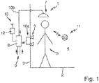
- a conventional shower 1 is shown with a floor 2 and a left wall 3 and a right wall 4.
- An operator 5 stands in the shower 1 and can use two side showers 6 and / or an overhead shower 7 on the left wall 3.
- more showers or the like could be used.
- These showers are fed by a sanitary fitting 8 mounted behind or in the wall, which advantageously has a thermostat function and a valve or distribution function.
- Two feed lines 9 lead into the sanitary fitting 8, as usual one for cold water and one for hot water.
- Feed lines 10a lead out to the side showers 6 and 10b to the overhead shower 7.
- the operator 5 can operate the sanitary fitting 8 by means of an operating device 11 according to the invention arranged on the right wall 4, specifically by turning and / or pressing.
- the operating device 11 transmits the signals generated by its operation to a control 12 with an antenna 13.
- the control 12 is connected to the sanitary fitting 8 and controls it accordingly, advantageously in a manner known per se by means of servomotors, servo valves and electromagnets or like that.
- the operator 5 can use the operating device 11 to distribute the water between the side showers 6 and the overhead shower 7, start or stop a water flow at all, and also set a temperature for the water. This is also known per se from the prior art.
- the operating device 11 according to the invention is specially constructed, as will be explained in detail below.
- a closed operating device 11 is shown in an oblique view from the side from the front. It has a partially rotatable control knob 15 with an actuating ring 45 running around the outside. The control knob 15 can be rotated on this actuating ring 45, for example to choose between various menu items, settings or functions.
- the control knob 15 also has a front glass 60. A light indicator can be provided thereon, which is shown in the Fig. 1 indicated as number "30" can be recognized.
- the base holder 17 On the back of the operating device 11 is the base holder 17, which is on a wall, for example on the right wall 4 according to FIG Fig. 1 , can be attached or can be attached. It can be permanently attached, for example screwed or glued on. Alternatively, it can be formed by latching or clipping into yet another holder, which in turn is permanently connected to the right wall 4.
- the control knob 15 is held on the base bracket.
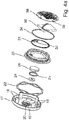
- the base bracket 17 can be seen on the left. It is also applied to the enlarged view of the Figure 4a and the sectional view of Fig. 5 referenced.
- the base holder 17 is approximately shell-like and has four holding tongues 18 protruding from a base.
- a spring ring 22 to be inserted runs around this, corresponding to the aforementioned spring, which is advantageously designed as a so-called wave spring. It is advantageously made of plastic or corrosion-free metal.
- a ring-shaped, recessed magnet receptacle 19 is provided in the center of the bottom of the base holder 17 with a central protruding projection 20.
- the push magnet 24, which is designed as a magnetic ring, is inserted here. It is diametrically magnetized in a plane perpendicular to an axis of rotation, represented here by the north pole "N" on the left and the south pole “S” on the right.
- the magnet receptacle 19 is closed by a cover 26 provided with a sealing ring 25 on the inside when the push magnet 24 is inserted. From the representation of the Fig. 5 it can be seen that the push magnet 24 has so much play around the projection 20 that it can rotate easily.
- the push magnet 24 should only be able to move as little as possible, or better not at all, in a direction along the axis of rotation D shown in dash-dotted lines, so that it is almost in contact with the cover 26.
- the control knob 15 which begins to the right of the cover 26 in the exploded views, has a lower housing part 29.
- a coil 31 with a coil connection 32 is provided, which is provided for inductive charging of an accumulator 36.
- An O-ring 34 is provided for sealing, which is also in the Fig. 5 can be seen because it lies in a recess on the outside of the lower housing part 29.
- a circuit board 38 is mounted on the lower housing part 29 and has, among other things, a plurality of LEDs 39 on its upper side. These generate the aforementioned illuminated display.
- a 3-D Hall sensor 62 mentioned at the beginning is arranged and electrically connected.
- a magnetic receiving ring 40 which has several differently arranged receiving pockets 41, runs around the lower housing part 29 and also around the holding tongues 18.
- permanent magnets 42 are arranged as the aforementioned magnetic elements, which are rod-shaped. You are according to Fig. 5 magnetized in a direction parallel to the direction of rotation D, which in Fig. 5 is also shown by way of example.
- the actuating ring 45 encompassing the outside has a lower groove ring 43 and an upper groove ring 48, which are designed as elastic rubber seals. They are used for sealing, like that Fig. 5 shows.
- the lower groove ring 43 seals the actuating ring 45 from below against the upstanding circumferential edge of the base holder 17.
- the upper groove ring 48 seals the actuating ring 45 against the round front glass 60.
- An upper housing part 50 is provided within the actuating ring 45.
- Holding recesses 51, into which the holding tongues 18 of the base holder 17 can engage, are formed on a downwardly projecting flange-like projection thereof.
- the upper housing part 50 is held non-rotatably on the base holder 17, but can be moved in the direction along the axis of rotation D and thus also pressed in, as will be explained in more detail below.
- a type of opening matrix 52 is provided with nothing but openings that each correspond to one of the LEDs 39. You can for example be provided with lenses or other similar optical devices.
- a diffuser film 54 is placed or glued in front of the opening matrix 52 for a better visual representation.
- a star disk 56 rests on the front of the upper housing part 50. This interacts with the permanent magnets 42 on the magnet receiving ring 40, which is held in a rotationally fixed manner by means of recesses 46 in the actuating ring 45, in such a way that a type of magnetic latching is achieved.
- Rotation of the rotatable control knob 15 relative to the inner part, namely this star disk 56 including the upper housing part 50, lower housing part 29 and base bracket 17, can be rasterized with a raster perceptible to the operator corresponding to the design of the star disc 56 Prior art also known.
- the star disk 56 is held on the front side of the upper housing part 50 by means of a double-sided adhesive pad 58 which is glued to the underside of the front glass 60 and thus also ensures a seal towards the front.
- the initially mentioned rotary control of the control knob 15 is thus mainly formed by the actuating ring 45 with the magnetic mounting ring 40 held therein in a rotationally fixed manner.
- the initially mentioned fixed control is mainly formed by the other parts of the control knob 15, in particular rotates due to the engagement the holding tongues 18 in the holding recesses 51 do not have the housing consisting of the parts 29 and 50 and thus also not the illuminated display which is formed by the LED 39.
- an operator 5 can always easily and precisely recognize what is displayed on it, even when turning the operating knob 15 while operating the operating device 11.
- the entire control knob 15 is in turn held or arranged on the base bracket 17, advantageously only removable by means of considerable force or a tool. It can be pressed in in relation to this, namely against the force of the spring ring 29.
- the lower groove ring 43 which is held on the inside of the actuating ring 45, moves downward on the base holder 17. However, it retains its sealing effect so that no water can enter here.
- the components of the control knob 15 that cannot be turned are thus also pressed in or pressed towards the base holder 17. As a result, the 3D Hall sensor 62 also moves towards the push magnet 24.
- Actuating travel to be recognized for example between the underside of the lower housing part 29 below the accumulator 36 and the top of the cover 26, can in practice be approximately 0.5 mm to 1 mm, so that it is clearly perceived by an operator.
- This actuation path which appears to be relatively small, can also be recognized well by the 3D Hall sensor 62 as it is approaching the push magnet 24.
- the 3D Hall sensor 62 can also detect a rotation of the permanent magnets 42 around it with respect to an angle of rotation, so that a rotary actuation of the control knob 15 can also be detected.
- different individual Hall sensors are provided within the 3D Hall sensor, advantageously one for detecting the approach to the push magnet 24 and one or two others in order to detect different magnetic field lines emanating from the permanent magnets 42 during rotation.
- the invention advantageously creates an accuracy of recognition by the rotatability of the push magnet 24.
- the distance to the 3D Hall sensor 62 does not change, so that it does not detect any signal change or change in the magnetic field strength, which it would otherwise see as an approach to the push magnet 24 and thus as an impression of the Control knob would recognize according to an operation by pressing.
- the push magnet 24 rotates with the actuating ring 45 through interaction with the permanent magnets 42, so that here there is always a constant magnetic field between the magnets 24 and 42. It does not change in the direction parallel to the axis of rotation D, so that no approach corresponding to an indentation to the push magnet 24 is detected either.
- the magnetic field naturally changes precisely due to the rotation, so that it can be recognized and evaluated by the 3-D Hall sensor 62.
- the 3D Hall sensor 62 is also arranged in the center of the circular path of the permanent magnets 42, so that the distance is always the same or remains the same.
- An evaluation device 64 is provided on the underside of the printed circuit board 38 to the left of the 3D Hall sensor 62. This evaluates the signals from the 3-D Hall sensor 62 and can thus detect whether it has approached the push-button magnet 24 when the control knob 15 is pushed in against the base bracket 17. The evaluation device 64 can also recognize whether the actuating ring 45 with the permanent magnets 42 in the magnet receiving ring 40 has been rotated around the non-rotatable 3D Hall sensor 62. The evaluation device 64 can precisely detect both movements and then transmit them to the antenna 13 of the control 12 by means of a transmission device (not shown) which is advantageously also provided on the circuit board 38. Various radio standards can be provided here, for example Bluetooth or BLE, Zigbee, WiFi or others.
- the wireless inductive charging of the accumulator 36 is possible if the operating device 11 is placed on a corresponding charging station. This is known from cell phones.
- the 3D Hall sensor 62 could be in Fig. 5 instead of being arranged above the accumulator 36, that is to say between the accumulator 36 and the lower housing part 29, of course again lying on the axis of rotation D. Then the accumulator 36 does not interfere with the magnetic field detection, which improves the accuracy. In this case, the 3-D Hall sensor 62 can then be arranged and electrically connected on a flexible printed circuit board or the like, which is guided downward from the printed circuit board 38 laterally around the accumulator 36. By means of a precisely fitting indentation in the top of the lower housing part 29, it can be positioned precisely on the axis of rotation D and at a constant distance from the push magnet 24.
Landscapes
- Engineering & Computer Science (AREA)
- Water Supply & Treatment (AREA)
- Public Health (AREA)
- Hydrology & Water Resources (AREA)
- Life Sciences & Earth Sciences (AREA)
- Health & Medical Sciences (AREA)
- General Physics & Mathematics (AREA)
- Physics & Mathematics (AREA)
- Computer Networks & Wireless Communication (AREA)
- Automation & Control Theory (AREA)
- Rotary Switch, Piano Key Switch, And Lever Switch (AREA)
- Measuring Volume Flow (AREA)
- Domestic Plumbing Installations (AREA)
- Mechanical Control Devices (AREA)
- Switches With Compound Operations (AREA)
Abstract
Description
- Die Erfindung bezieht sich auf eine Bedienvorrichtung für eine wasserführende sanitäre Armatur, die eine ortsfest befestigte oder befestigbare Basishalterung und einen an der Basishalterung angeordneten Bedienknebel aufweist. Der Bedienknebel weist mindestens zwei Teile auf, nämlich mindestens ein Dreh-Bedienteil und mindestens ein Fest-Bedienteil, die gegeneinander verdrehbar sind.
- Eine Bedienvorrichtung der eingangs genannten Art ist in den Patentschriften
EP 2 250 321 B1 undEP 2 267 232 B1 offenbart. - Der Erfindung liegt als technisches Problem die Bereitstellung einer Bedienvorrichtung der eingangs genannten Art zugrunde, die eine Bedienung einer wasserführenden sanitären Armatur verbessert und sehr komfortabel ermöglicht, wobei insbesondere deren Bedienknebel signifikante Anwendungsvorteile bietet.
- Die Erfindung löst dieses Problem durch die Bereitstellung einer Bedienvorrichtung für eine wasserführende sanitäre Armatur mit den Merkmalen des Anspruchs 1. Bei dieser Bedienvorrichtung sind eine ortsfest befestigte oder befestigbare Basishalterung und ein an der Basishalterung angeordneter Bedienknebel vorgesehen. Der Bedienknebel weist mindestens zwei Teile auf, nämlich mindestens ein Dreh-Bedienteil und mindestens ein Fest-Bedienteil, wobei Dreh-Bedienteil und Fest-Bedienteil gegeneinander verdrehbar sind.
- Dabei ist zumindest der Dreh-Bedienteil des Bedienknebels an der Basishalterung um eine Drehachse drehbar, kann also gedreht werden. Vorteilhaft kann er um eine Drehachse senkrecht zu einer Wand oder Unterlage gedreht werden, an der er befestigt ist. Zumindest ein Teil des Bedienknebels kann aus einer Grund-Stellung entlang der Drehachse gegen eine Federkraft einer Feder eingedrückt werden auf die Basishalterung zu in eine Eindrück-Stellung. Diese kann durch einen Anschlag als Eindrück-Anschlag genau definiert werden. Die Feder drückt den Bedienknebel mit der Federkraft von der Eindrück-Stellung in die Grund-Stellung, kann ihn also zurückdrücken. So bewegt er sich nach einem Eindrücken selbsttätig wieder zurück bzw. wieder heraus. In der Basishalterung ist mindestens ein Drück-Magnet angeordnet, der vorteilhaft als Permanentmagnet ausgebildet ist. Im eindrückbaren Teil des Bedienknebels ist mindestens ein Magnetfeldsensor angeordnet, vorteilhaft ein Hallsensor.
- Für den Magnetfeldsensor ist eine Auswertevorrichtung in der Bedienvorrichtung bzw. im Bedienknebel vorgesehen, die dazu ausgebildet ist, erkennen zu können, ob sich der Magnetfeldsensor beim Eindrücken des eindrückbaren Teils des Bedienknebels an den Drück-Magnet annähert oder davon entfernt. So kann das Eindrücken des eindrückbaren Teils erkannt werden bzw. dessen Stellung in Richtung auf die Basishalterung zu. Des Weiteren ist im Dreh-Bedienteil des Bedienknebels mindestens ein Magnetelement angeordnet, vorteilhaft mehrere. Sie können dazu verwendet werden, eine Drehung des Bedienteils bzw. des Bedienknebels zu erkennen, vorteilhaft wiederum über einen Magnetfeldsensor.
- Erfindungsgemäß ist der Drück-Magnet drehbar gelagert um eine eigene Achse, die der Drehachse des Dreh-Bedienteils entspricht bzw. auf ihr liegt. Somit liegt der Drück-Magnet zentrisch zum Dreh-Bedienteil. Der Drück-Magnet soll mit dem Magnetelement derart wechselwirken, dass sich der Drück-Magnet mit einer Drehung des Magnetelements samt dem Dreh-Bedienteil des Bedienknebels mitdreht. Somit soll der Drück-Magnet immer dieselbe Stellung relativ zu dem mindestens einen Magnetelement oder zu allen Magnetelementen aufweisen, die gedreht werden können. Dadurch kann es erreicht werden, dass das zwischen ihnen ausgebildete Magnetfeld immer gleich ist, unabhängig von der Dreh-Stellung des Bedienknebels bzw. des Dreh-Bedienteils. Das ermöglicht es dem vorgenannten Magnetfeldsensor, besonders genau und störungsfrei eine Annäherung an den Drück-Magnet zu erkennen, und unabhängig von einer Drehung bzw. vor allem auch von einer Drehung des Dreh-Bedienteils zwischen den beiden Stellungen zu unterscheiden.
- In einer Weiterbildung der Erfindung ist der Drück-Magnet rotationssymmetrisch ausgebildet. Vorteilhaft ist er als Scheibe oder als Kreisring ausgebildet. Die Drehachse des Dreh-Bedienteils kann durch einen Mittelpunkt und Rotationssymmetriepunkt des Drück-Magneten verlaufen, wobei bevorzugt die beiden Drehachsen zusammenfallen bzw. gleich sind.
- In einer vorteilhaften Weiterbildung der Erfindung kann der Drück-Magnet in Richtung entlang der Drehachse, also auf die Basishalterung zu, maximal 1 mm bzw. 25% des Bewegungswegs des Bedienknebels beim Drücken auf die Basishalterung zu bewegt werden. Dieses Spiel sollte aber vorteilhaft möglichst gering sein, so dass es zwar ein leichtgängiges Drehen des Drück-Magneten erlaubt, aber keine nennenswerte Bewegung des Drück-Magneten auf den Magnetfeldsensor zu ermöglicht. Besonders vorteilhaft ist der Drück-Magnet in Richtung entlang der Drehachse gar nicht bewegbar. Eine Drehbarkeit des Drück-Magneten kann durch entsprechende Materialien, vorteilhaft Beschichtungen, verbessert werden, insbesondere innerhalb einer Aufnahme für den Drück-Magnet an bzw. in der Basishalterung.
- In einer Ausgestaltung der Erfindung ist der als Permanentmagnet ausgebildete Drück-Magnet diametral magnetisiert, so kann seine Nord-Süd-Richtung in einer Richtung senkrecht zur Drehachse verlaufen. Bei einem Drück-Magnet in Ringform kann eine Hälfte des Rings einen Nordpol bilden, und die andere Hälfte des Rings bildet dann einen Südpol.
- In weiterer Ausgestaltung der Erfindung ist das mindestens eine Magnetelement im Dreh-Bedienteil ein Permanentmagnet, insbesondere mit Magnetisierung mit Nord-Süd-Richtung in einer Richtung parallel zur Drehachse des Dreh-Bedienteils. Dabei können bevorzugt mehrere Magnetelemente als Permanentmagnete im Bedienknebel angeordnet sein. Sie können identisch ausgebildet sein, wodurch der Aufwand reduziert werden kann. Möglicherweise können die Magnetelemente unterschiedlich angeordnet sein, beispielsweise einige, insbesondere die eine Hälfte, mit umgekehrter Magnetisierung als die andere Hälfte. Diese Aufteilung in Hälften kann entsprechend je einem Halbkreis des Dreh-Bedienteils erfolgen, beispielsweise damit der entsprechend magnetisierte Drück-Magnet sich genau korrespondierend dazu ausrichten kann. Diese Ausrichtung kann er dann auch einhalten, unabhängig von einem Eindrücken des Bedienknebels.
- In nochmals weiterer Ausgestaltung der Erfindung ist das mindestens eine Magnetelement im Dreh-Bedienteil nahe an einem äußeren Rand des Dreh-Bedienteils angeordnet. Vorteilhaft sind alle Magnetelemente im Dreh-Bedienteil so angeordnet, vorteilhaft entlang einem Kreis, durch dessen Mittelpunkt die Drehachse verläuft. Die Magnetelemente können einen Abstand zueinander aufweisen, wobei dieser nicht immer gleich sein muss zwischen diesen.
- In nochmals weiterer Ausgestaltung der Erfindung ist die Feder, gegen die der Bedienknebel eingedrückt werden kann, ringförmig ausgebildet. Ein Mittelpunkt kann auf der Drehachse liegen bzw. mit ihr zusammenfallen. Die Feder liegt vorteilhaft relativ weit außen nahe einem Außenrand des Bedienknebels, wodurch ihre Federwirkung gleichmäßiger sein kann. Die Feder ist vorteilhaft als eine Wellfeder ausgebildet, wobei sie zwei spiegelsymmetrisch gewellte Ringe aus federelastischem Material aufweisen kann, die eine Spiegelebene senkrecht zur Drehachse aufweisen. Alternativ könnten auch mehrere kleinere Federn im Kreis verteilt angeordnet sein.
- Bevorzugt ist der Drück-Magnet in einer Ausnehmung angeordnet, die in etwa seiner Form entspricht, also beispielsweise kreisringförmig ist. Zusätzlich oder alternativ kann er auf einem Vorsprung der Basishalterung sitzend angeordnet sein, wobei bevorzugt dieser Vorsprung als eine Art Drehlagerung ausgebildet ist. Eine Abdeckung, vorteilhaft nach Art eines Deckels odgl., kann den Drück-Magnet in der Ausnehmung haltern. Sie kann insbesondere als runder Deckel ausgebildet sein, ggf. mit einem abstehenden und übergreifenden Rand. Dieser Deckel kann den Drück-Magnet wasserdicht nach außen abdecken, wobei er natürlich seine leichtgängige Drehbarkeit behalten sollte.
- Vorteilhaft kann der Magnetfeldsensor im Fest-Bedienteil angeordnet und dabei drehfest gehalten sein, besonders vorteilhaft von der Basishalterung. Der Magnetfeldsensor soll sich also nicht mitdrehen müssen oder vorteilhaft nicht mitdrehen können, da eine relative Drehung zu den drehbaren Magnetelementen erkannt werden können soll, er soll nur mit dem eindrückbaren Teil des Bedienknebels auf den Drück-Magnet zu bewegt werden können.
- In Ausgestaltung der Erfindung ist der Bedienknebel zweiteilig ausgebildet mit dem Fest-Bedienteil als Innenteil, das drehfest von der Basishalterung gehalten ist bzw. von dieser am Drehen gehindert ist, vorteilhaft durch einen Formschluss wie beispielsweise abstehende Haltezungen odgl.. Um den Fest-Bedienteil herum ist der demgegenüber drehbare Dreh-Bedienteil als Betätigungsring vorgesehen, der mit seinem Außenrand einen Außenrand des Bedienknebels bilden kann, der also durch eine Bedienperson zum Drehen gegriffen werden kann. Das mindestens eine Magnetelement ist dabei im oder am Dreh-Bedienteil gehalten, da es sich ja drehen können soll.
- In weiterer Ausgestaltung der Erfindung weist der Bedienknebel nur den drehbaren Dreh-Bedienteil und den Fest-Bedienteil auf, also nur zwei Teile. Diese wiederum weisen natürlich mehrere Komponenten bzw. Funktionseinheiten auf. Vorteilhaft ist der gesamte Bedienknebel eindrückbar auf die Basishalterung zu, also Dreh-Bedienteil und Fest-Bedienteil gemeinsam. Dies ist eine möglichst einfache Ausgestaltung, die dann natürlich auch leichter wasserdicht sein kann. Alternativ ist es aber auch möglich, dass nur ein Teil des Bedienknebels eingedrückt werden kann, beispielsweise der Fest-Bedienteil. Dies ist besonders dann von Vorteil, wenn der Magnetfeldsensor darin angeordnet ist.
- Der Bedienknebel kann vorteilhaft mit der Basishalterung eine Baueinheit bilden, also zusammen mit dieser oder mittels dieser ortsfest angeordnet bzw. befestigt werden, beispielsweise an einer Wand. Dazu kann an der Rückseite der Basishalterung ein formschlüssiges Befestigungsmittel odgl. vorgesehen sein, beispielsweise um sie in einen Wandhalter einzuhängen.
- In nochmals weiterer Ausgestaltung der Erfindung weist der Fest-Bedienteil eine Anzeige aufweist, die vorzugsweise als Leuchtanzeige ausgebildet sein kann. Diese kann LED aufweisen, die auf bekannte Art und Weise angeordnet werden können und leuchten können. Es können auch hinterleuchtete Displays sein, beispielsweise mit TFT-Technik.
- Der Magnetfeldsensor kann als Baueinheit ausgebildet sein mit weiteren Magnetfeldsensoren zusammen, um eine Drehung des Dreh-Bedienteils relativ zu der Basishalterung erkennen zu können. Er kann vorteilhaft als 3D-Magnetfeldsensor bzw. als 3D-Hallsensor ausgebildet sein, wie sie aus dem Stand der Technik an sich bekannt sind. Sie können Änderungen eines Magnetfelds in verschiedenen Richtungen bzw. mit verschiedenen Magnetisierungsrichtungen messen. Eine solche Baueinheit kann eine gemeinsame Anschlusseinrichtung aufweisen.
- Bevorzugt ist im Bedienknebel eine Signalauswertung für den Magnetfeldsensor vorgesehen, die einen integrierten Schaltkreis aufweisen kann, vorteilhaft einen Controller oder Microcontroller. Diese Signalauswertung kann auf übliche Art und Weise ausgebildet sein, insbesondere eben für 3D-Magnetfeldsensor bzw. 3D-Hallsensoren. Die Signalauswertung selbst kann eine Sendeeinrichtung aufweisen zum drahtlosen Senden bzw. Übertragen der Daten bzgl. der erkannten Drehstellung und/oder Drückstellung des Bedienknebels relativ zur Basishalterung an eine Steuerung zur Ansteuerung der wasserführenden sanitären Armatur. Alternativ kann diese Sendeeinrichtung separat in der Bedienvorrichtung bzw. im Bedienknebel vorgesehen sein. Verschiedene allgemein bekannte und geeignete Standards m drahtlosen Senden bzw. Übertragen der Daten können verwendet werden.
- Der Bedienknebel weist vorteilhaft eine eigene Energieversorgung auf, vorzugsweise einen Akkumulator. Ein solcher Akkumulator ist bevorzugt im Fest-Bedienteil angeordnet. Er kann bei abgenommenem Bedienknebel geladen werden, vorzugsweise induktiv, wie dies bekannt ist. Dazu kann eine entsprechende Spule im Bedienknebel vorgesehen sein. Dann werden keine elektrischen Kontakte benötigt, die bei der feuchten Umgebung der Bedienvorrichtung in einer Dusche odgl. korrodieren könnten und somit Probleme verursachen könnten.
- Vorteilhafte Ausführungsbeispiele der Erfindung sind in den Zeichnungen dargestellt. Diese und weitere vorteilhafte Ausführungsformen der Erfindung werden nach folgend beschrieben. Hierbei zeigen:
- Fig. 1
- eine schematische Darstellung einer Bedienvorrichtung, die in eine Dusche eingebaut ist,
- Fig. 2
- eine schräge Ansicht von der Seite auf die erfindungsgemäße Bedienvorrichtung mit einer befestigbaren Basishalterung, an der ein Bedienknebel angeordnet ist,
- Fig. 3
- Basishalterung und Bedienknebel der Bedienvorrichtung aus
Fig. 2 in Explosionsdarstellung, - Fig. 4a und 4b
- die Explosionsdarstellung der
Fig. 3 in Vergrößerung aufgeteilt auf zwei Darstellungen und - Fig. 5
- eine Schnittdarstellung durch die Bedienvorrichtung der
Fig. 2 . - In der
Fig. 1 ist eine an sich übliche Dusche 1 gezeigt mit einem Boden 2 und einer linken Wand 3 sowie einer rechten Wand 4. Eine Bedienperson 5 steht in der Dusche 1 und kann zwei Seitenbrausen 6 und/oder eine Kopfbrause 7 an der linken Wand 3 nutzen. Natürlich könnten noch mehr Brausen odgl. vorgesehen sein. Gespeist werden diese Brausen von einer hinter oder in der Wand angebrachten sanitären Armatur 8, die vorteilhaft Thermostatfunktion und Ventil- bzw. Verteilfunktion aufweist. In die sanitäre Armatur 8 führen zwei Zuleitungen 9, wie üblich eine für kaltes Wasser und eine für heißes Wasser. Heraus führen Zuführleitungen 10a zu den Seitenbrausen 6 und 10b zur Kopfbrause 7. - Bedienen kann die Bedienperson 5 die sanitäre Armatur 8 mittels einer an der rechten Wand 4 angeordneten Bedienvorrichtung 11 gemäß der Erfindung, und zwar durch Drehen und/oder Drücken. Die Bedienvorrichtung 11 funkt die durch ihre Bedienung erzeugten Signale an eine Ansteuerung 12 mit einer Antenne 13. Die Ansteuerung 12 ist mit der sanitären Armatur 8 verbunden und steuert diese entsprechend an, vorteilhaft auf an sich bekannte Art und Weise mittels Stellmotoren, Stellventilen und Elektromagneten oder dergleichen. So kann die Bedienperson 5 mittels der Bedienvorrichtung 11 beispielsweise das Wasser zwischen Seitenbrausen 6 und Kopfbrause 7 verteilen, einen Wasserfluss überhaupt starten oder stoppen sowie auch eine Temperatur für das Wasser einstellen. Auch dies ist an sich aus dem Stand der Technik bekannt. Die erfindungsgemäße Bedienvorrichtung 11 ist speziell aufgebaut, wie nachfolgend im Detail erläutert wird.
- In der
Fig. 2 ist eine geschlossene erfindungsgemäße Bedienvorrichtung 11 in schräger Ansicht seitlich von vorne dargestellt. Sie weist einen teilweise drehbaren Bedienknebel 15 auf mit einem außen umlaufenden Betätigungsring 45. An diesem Betätigungsring 45 kann der Bedienknebel 15 gedreht werden, beispielsweise um zwischen verschiedenen Menüpunkten, Einstellungen oder Funktionen zu wählen. Des Weiteren weist der Bedienknebel 15 noch ein Frontglas 60 auf. Daran kann eine Leuchtanzeige vorgesehen sein, die in derFig. 1 angedeutet als Zahl "30" zu erkennen ist. - An der Rückseite der Bedienvorrichtung 11 ist die Basishalterung 17, welche an einer Wand, beispielsweise an der rechten Wand 4 gemäß
Fig. 1 , befestigt sein kann oder befestigt werden kann. Sie kann dauerhaft befestigt sein, beispielsweise festgeschraubt oder angeklebt sein. Alternativ kann sie durch Rasten oder Einklipsen an einer nochmals weiteren Halterung ausgebildet sein, die wiederum dauerhaft fest mit der rechten Wand 4 verbunden ist. An der Basishalterung ist der Bedienknebel 15 gehalten. - In der gesamten Explosionsdarstellung der
Fig. 3 ist links die Basishalterung 17 zu sehen. Es wird auch auf die vergrößerte Darstellung derFig. 4a und die Schnittdarstellung derFig. 5 verwiesen. Die Basishalterung 17 ist in etwa schalenartig ausgebildet und weist von einem Boden abstehend vier Halte-Zungen 18 auf. Um diese herum verläuft ein einzulegender Federring 22 entsprechend der vorgenannten Feder, der vorteilhaft als sogenannte Wellfeder ausgebildet ist. Er besteht vorteilhaft aus Kunststoff oder korrosionsfreiem Metall. - Wie die vergrößerten Darstellungen zeigen, ist mittig am Boden der Basishalterung 17 eine ringförmig ausgebildete vertiefte Magnetaufnahme 19 vorgesehen mit einem mittigen abstehenden Vorsprung 20. Hier ist der Drück-Magnet 24 eingelegt, der als Magnetring ausgebildet ist. Er ist diametral magnetisiert in einer Ebene senkrecht zu einer Drehachse, hier dargestellt durch den Nordpol "N" links und den Südpol "S" rechts. Die Magnetaufnahme 19 wird durch einen mit einem Dichtungsring 25 innen versehenen Deckel 26 verschlossen, wenn der Drück-Magnet 24 eingelegt ist. Aus der Darstellung der
Fig. 5 ist zu ersehen, dass der Drück-Magnet 24 so viel Spiel um den Vorsprung 20 herum aufweist, dass er sich leicht drehen kann. Hier sind vorteilhaft möglichst glatte Oberflächen für eine leichte Drehbarkeit vorzusehen. Des Weiteren soll sich der Drück-Magnet 24 nur möglichst gering oder besser gar nicht in einer Richtung entlang der strichpunktiert dargestellten Drehachse D bewegen können, so dass er also nahezu am Deckel 26 anliegt. - Der Bedienknebel 15, der in den Explosionsdarstellungen rechts neben dem Deckel 26 beginnt, weist ein Gehäuseunterteil 29 auf. In diesem ist eine Spule 31 mit einem Spulenanschluss 32 vorgesehen, die für ein induktives Laden eines Akkumulators 36 vorgesehen ist. Zur Abdichtung ist ein O-Ring 34 vorgesehen, der auch in der
Fig. 5 zu erkennen ist, weil er in einer Ausnehmung außen am Gehäuseunterteil 29 liegt. - Auf den Gehäuseunterteil 29 wird eine Leiterplatte 38 montiert, die unter anderem auf ihrer Oberseite eine Vielzahl von LED 39 aufweist. Diese erzeugen die vorgenannte Leuchtanzeige. An der Unterseite der Leiterplatte 38 ist, vorteilhaft auf der Drehachse D, ein eingangs genannter 3D-Hall-Sensor 62 angeordnet und elektrisch angeschlossen.
- Um das Gehäuseunterteil 29 und auch um die Halte-Zungen 18 herum verläuft ein Magnet-Aufnahmering 40, der mehrere, unterschiedlich angeordnete Aufnahmetaschen 41 aufweist. In einigen von diesen Aufnahmetaschen sind Permanentmagnete 42 als vorgenannte Magnetelemente angeordnet, die stabförmig ausgebildet sind. Sie sind gemäß
Fig. 5 magnetisiert in einer Richtung parallel zur Drehrichtung D, was inFig. 5 auch beispielhaft jeweils eingezeichnet ist. - Der außen umgreifende Betätigungsring 45 weist einen unteren Nutring 43 und einen oberen Nutring 48 auf, die als elastische Gummidichtungen ausgebildet sind. Sie dienen zur Abdichtung, wie die
Fig. 5 zeigt. Der untere Nutring 43 dichtet den Betätigungsring 45 nach unten gegen den hochstehenden umlaufenden Rand der Basishalterung 17 ab. Der obere Nutring 48 dichtet den Betätigungsring 45 gegen das runde Frontglas 60 ab. - Innerhalb des Betätigungsrings 45 ist ein Gehäuseoberteil 50 vorgesehen. An einem nach unten abragenden flanschartigen Vorsprung davon sind Halte-Ausnehmungen 51 ausgebildet, in die die Halte-Zungen 18 der Basishalterung 17 eingreifen können. Dadurch ist das Gehäuseoberteil 50 drehfest an der Basishalterung 17 gehalten, kann allerdings in Richtung entlang der Drehachse D bewegt werden und somit auch eingedrückt werden, wie nachfolgend noch näher erläutert wird. Vorne an dem Gehäuseoberteil 50 ist eine Art Öffnungsmatrix 52 vorgesehen mit lauter Öffnungen, die jeweils einer der LED 39 entsprechen. Sie können beispielsweise mit Linsen oder sonstigen ähnlichen optischen Einrichtungen versehen sein. Vor die Öffnungsmatrix 52 wird eine Diffusorfolie 54 gelegt oder geklebt für eine bessere optische Darstellung.
- Vorne auf dem Gehäuseoberteil 50 liegt eine Sternscheibe 56 auf. Diese wirkt derart zusammen mit den Permanentmagneten 42 am Magnet-Aufnahmering 40, der drehfest mittels Ausnehmungen 46 im Betätigungsring 45 gehalten ist, dass eine Art magnetische Rasterung erreicht wird. So kann ein Drehen des drehbaren Bedienknebels 15 relativ zu dem inneren Teil, nämlich dieser Sternscheibe 56 samt Gehäuseoberteil 50, Gehäuseunterteil 29 und Basishalterung 17, gerastert sein mit einer für die Bedienperson fühlbaren Rasterung entsprechend der Ausgestaltung der Sternscheibe 56. Dies ist an sich aus dem Stand der Technik auch bekannt. Die Sternscheibe 56 wird an der Vorderseite des Gehäuseoberteils 50 mittels eines doppelseitigen Klebepads 58 gehalten, das mit der Unterseite des Frontglases 60 verklebt ist und so auch eine Abdichtung nach vorne sicherstellt.
- Der eingangs genannte Dreh-Bedienteil des Bedienknebels 15 wird also hauptsächlich gebildet von dem Betätigungsring 45 mit dem drehfest darin gehaltenen Magnet-Aufnahmering 40. Der eingangs genannte Fest-Bedienteil wird hauptsächlich von den übrigen Teilen des Bedienknebels 15 gebildet, insbesondere dreht sich aufgrund des Eingriffs der Halte-Zungen 18 in die Halte-Ausnahmen 51 das aus den Teilen 29 und 50 bestehende Gehäuse nicht und somit auch nicht die Leuchtanzeige, die von den LED 39 gebildet wird. Somit kann eine Bedienperson 5 auch beim Drehen des Bedienknebels 15 während einer Bedienung der Bedienvorrichtung 11 stets leicht und genau erkennen, was daran angezeigt wird.
- Der gesamte Bedienknebel 15 wiederum ist an der der Basishalterung 17 gehalten bzw. angeordnet, vorteilhaft nur mittels erheblicher Kraft oder Werkzeug entfernbar. Er kann gegenüber dieser eingedrückt werden, und zwar gegen die Kraft des Federrings 29. Der untere Nutring 43, der an der Innenseite des Betätigungsrings 45 gehalten ist, verschiebt sich dabei an der Basishalterung 17 nach unten. Er behält jedoch seine Dichtwirkung, so dass hier kein Wasser eintreten kann. Somit werden auch die Bauteile des Bedienknebels 15, die nicht gedreht werden können, eingedrückt bzw. auf die Basishalterung 17 zu gedrückt. Dadurch bewegt sich auch der 3D-Hall-Sensor 62 auf den Drück-Magnet 24 zu. Der in der
Fig. 5 zu erkennende Betätigungsweg, beispielsweise zwischen Unterseite des Gehäuseunterteils 29 unterhalb des Akkumulators 36 und der Oberseite des Deckels 26, kann in der Praxis etwa 0,5 mm bis 1 mm betragen, so dass er deutlich von einer Bedienperson wahrgenommen wird. Dieser relativ gering erscheinende Betätigungsweg kann auch von dem 3D-Hall-Sensor 62 als Annäherung an den Drück-Magnet 24 gut erkannt werden. Des Weiteren kann der 3D-Hall-Sensor 62 auch noch eine Drehung der Permanentmagnete 42 um ihn herum erfassen bezüglich eines Drehwinkels, so dass auch eine Drehbetätigung des Bedienknebels 15 erkannt werden kann. Hierfür sind innerhalb des 3D-Hall-Sensors unterschiedliche einzelne HallSensoren vorgesehen, vorteilhaft einer für die Erkennung der Annäherung an den Drück-Magnet 24 und einer oder zwei weitere, um unterschiedliche Magnetfeldlinien ausgehend von den Permanentmagneten 42 bei Drehung zu erkennen. - Hier ist auch offensichtlich, warum es die Erfindung vorteilhaft schafft, durch die Drehbarkeit des Drück-Magneten 24 eine Genauigkeit einer Erkennung zu verbessern. Durch diese Drehbarkeit des Drück-Magneten 24 ändert sich der Abstand zu dem 3D-Hall-Sensor 62 ja nicht, so dass dieser auch keine Signalveränderung oder Magnetfeldstärkeänderung erkennt, welche er ansonsten als Annäherung an den Drück-Magneten 24 und somit als ein Eindrücken des Bedienknebels entsprechend einem Bedienvorgang durch Drücken erkennen würde. Der Drück-Magnet 24 dreht sich nämlich durch Wechselwirkung mit den Permanentmagneten 42 mit dem Betätigungsring 45 mit, so dass hier ein an sich stets gleiches Magnetfeld zwischen den Magneten 24 und 42 besteht. Es ändert sich in Richtung parallel zur Drehachse D nicht, so dass eben auch keine Annäherung entsprechend einem Eindrücken zum Drück-Magnet 24 erkannt wird. In der Ebene senkrecht zur Drehachse D durch den 3D-Hall-Sensor 62 ändert sich das Magnetfeld natürlich gerade aufgrund der Drehung, so dass diese von dem 3D-Hall-Sensor 62 eben erkannt und ausgewertet werden kann. Der 3D-Hall-Sensor 62 ist auch im Mittelpunkt der Kreisbahn der Permanentmagnete 42 angeordnet, so dass der Abstand immer derselbe ist bzw. gleich bleibt.
- An der Unterseite der Leiterplatte 38 ist links neben dem 3D-Hall-Sensor 62 eine Auswertevorrichtung 64 vorgesehen, vorteilhaft ein integrierter Schaltkreis. Diese wertet die Signale des 3D-Hall-Sensors 62 aus und kann somit erkennen, ob sich dieser beim Eindrücken des Bedienknebels 15 gegen die Basishalterung 17 an den Drück-Magnet 24 angenähert hat. Ebenso kann die Auswertevorrichtung 64 erkennen, ob der Betätigungsring 45 mit den Permanentmagneten 42 im Magnet-Aufnahmering 40 um den nicht-drehbaren 3D-Hall-Sensor 62 herum gedreht worden ist. Beide Bewegungen kann die Auswertevorrichtung 64 genau erkennen und dann mittels einer nicht dargestellten Sendeeinrichtung, die vorteilhaft ebenfalls an der Leiterplatte 38 vorgesehen ist, an die Antenne 13 der Ansteuerung 12 senden. Hier können verschiedene Funkstandards vorgesehen sein, beispielsweise Bluetooth bzw. BLE, Zigbee, WiFi oder sonstige.
- Das drahtlose induktive Laden des Akkumulators 36 ist möglich, wenn die Bedienvorrichtung 11 auf eine entsprechende Ladestation gelegt wird. Dies ist ja von Mobiltelefonen bekannt.
- Der 3D-Hall-Sensor 62 könnte in
Fig. 5 auch anstelle über dem Akkumulator 36 darunter angeordnet sein, also zwischen Akkumulator 36 und Gehäuseunterteil 29, natürlich wiederum auf der Drehachse D liegend. Dann stört der Akkumulator 36 die Magnetfelderkennung nicht, was die Genauigkeit verbessert. Dabei kann der 3D-Hall-Sensor 62 dann auf einer flexiblen Leiterplatte oder dergleichen angeordnet und elektrisch angeschlossen sein, die von der Leiterplatte 38 aus seitlich um den Akkumulator 36 herum nach unten geführt ist. Mittels einer passgenauen Vertiefung in der Oberseite des Gehäuseunterteils 29 kann er genau auf der Drehachse D und mit gleichbleibendem Abstand zum Drück-Magnet 24 positioniert werden.
Claims (15)
- Bedienvorrichtung für eine wasserführende sanitäre Armatur, wobei die Bedienvorrichtung aufweist:- eine ortsfest befestigbare Basishalterung,- einen an der Basishalterung angeordneten Bedienknebel, der mindestens zwei Teile aufweist, nämlich mindestens ein Dreh-Bedienteil und mindestens ein Fest-Bedienteil, wobei Dreh-Bedienteil und Fest-Bedienteil gegeneinander verdrehbar sind,wobei:- zumindest der Dreh-Bedienteil des Bedienknebels ist drehbar um eine Drehachse,- zumindest ein Teil des Bedienknebels ist aus einer Grund-Stellung entlang der Drehachse gegen eine Federkraft einer Feder eindrückbar auf die Basishalterung zu in eine Eindrück-Stellung,- die Feder drückt den Bedienknebel mit der Federkraft von der Eindrück-Stellung in die Grund-Stellung,- in der Basishalterung ist mindestens ein Drück-Magnet angeordnet,- im eindrückbaren Teil des Bedienknebels ist mindestens ein Magnetfeldsensor angeordnet,- eine Auswertevorrichtung ist für den Magnetfeldsensor vorgesehen, die dazu ausgebildet ist, um zu erkennen, ob sich der Magnetfeldsensor beim Eindrücken des eindrückbaren Teils des Bedienknebels an den Drück-Magnet annähert,- im Dreh-Bedienteil des Bedienknebels ist mindestens ein Magnetelement angeordnet,
dadurch gekennzeichnet, dass- der Drück-Magnet drehbar gelagert ist um die Drehachse des Dreh-Bedienteils des Bedienknebels,- der Drück-Magnet mit dem Magnetelement derart wechselwirkt, dass sich der Drück-Magnet mit einer Drehung des Magnetelements samt dem Dreh-Bedienteil des Bedienknebels mitdreht. - Bedienvorrichtung nach Anspruch 1, dadurch gekennzeichnet, dass der Drück-Magnet rotationssymmetrisch ausgebildet ist, insbesondere als Scheibe oder als Kreisring ausgebildet ist, wobei vorzugsweise die Drehachse durch einen Mittelpunkt und Rotationssymmetriepunkt des Drück-Magneten verläuft.
- Bedienvorrichtung nach einem der vorhergehenden Ansprüche, dadurch gekennzeichnet, dass der Drück-Magnet in Richtung entlang der Drehachse maximal 1 mm bzw. 25% des Bewegungswegs des Bedienknebels beim Drücken auf die Basishalterung zu bewegbar ist, wobei vorzugsweise der Drück-Magnet in Richtung entlang der Drehachse nicht bewegbar ist.
- Bedienvorrichtung nach einem der vorhergehenden Ansprüche, dadurch gekennzeichnet, dass der Drück-Magnet diametral magnetisiert ist mit Nord-Süd-Richtung in einer Richtung senkrecht zur Drehachse.
- Bedienvorrichtung nach einem der vorhergehenden Ansprüche, dadurch gekennzeichnet, dass das Magnetelement im Dreh-Bedienteil ein Permanentmagnet ist, insbesondere mit Nord-Süd-Richtung in einer Richtung parallel zur Drehachse, wobei vorzugsweise mehrere Magnetelemente im Bedienknebel angeordnet sind.
- Bedienvorrichtung nach Anspruch 5, dadurch gekennzeichnet, dass das mindestens eine Magnetelement im Dreh-Bedienteil, vorzugsweise alle Magnetelemente, nahe an einem äußeren Rand des Dreh-Bedienteils angeordnet sind, vorzugsweise entlang einem Kreis, durch dessen Mittelpunkt die Drehachse verläuft.
- Bedienvorrichtung nach einem der vorhergehenden Ansprüche, dadurch gekennzeichnet, dass die Feder ringförmig verläuft, vorzugweise mit einem Mittelpunkt auf der Drehachse, wobei vorzugsweise die Feder eine Wellfeder ist aus zwei spiegelsymmetrisch gewellten Ringen aus federelastischem Material mit Spiegelebene senkrecht zur Drehachse.
- Bedienvorrichtung nach einem der vorhergehenden Ansprüche, dadurch gekennzeichnet, dass der Drück-Magnet in einer seiner Form entsprechenden Ausnehmung angeordnet ist und/oder auf einem Vorsprung der Basishalterung sitzend angeordnet ist, wobei vorzugsweise eine wasserdichte Abdeckung, insbesondere als runder Deckel, den Drück-Magnet haltert und wasserdicht abdeckt nach außen.
- Bedienvorrichtung nach einem der vorhergehenden Ansprüche, dadurch gekennzeichnet, dass der Magnetfeldsensor im Fest-Bedienteil angeordnet ist und drehfest gehalten ist von der Basishalterung, wobei vorzugsweise der Bedienknebel zweiteilig ausgebildet ist mit dem Fest-Bedienteil als Innenteil, das drehfest von der Basishalterung gehalten ist, wobei um den Fest-Bedienteil der demgegenüber drehbare Dreh-Bedienteil als Betätigungsring vorgesehen ist, der mit seinem Außenrand einen Außenrand des Bedienknebels bildet.
- Bedienvorrichtung nach Anspruch 9, dadurch gekennzeichnet, dass das mindestens eine Magnetelement im oder am Dreh-Bedienteil gehalten ist.
- Bedienvorrichtung nach einem der vorhergehenden Ansprüche, dadurch gekennzeichnet, dass der Bedienknebel nur den drehbaren Dreh-Bedienteil und den Fest-Bedienteil aufweist, wobei der gesamte Bedienknebel eindrückbar ist.
- Bedienvorrichtung nach einem der vorhergehenden Ansprüche, dadurch gekennzeichnet, dass der Fest-Bedienteil eine Anzeige aufweist, vorzugsweise als Leuchtanzeige.
- Bedienvorrichtung nach einem der vorhergehenden Ansprüche, dadurch gekennzeichnet, dass der Magnetfeldsensor als Baueinheit ausgebildet ist mit weiteren Magnetfeldsensoren zur Erkennung einer Drehung des Dreh-Bedienteils relativ zu der Basishalterung, wobei vorzugsweise die Baueinheit eine gemeinsame Anschlusseinrichtung aufweist, wobei insbesondere der Magnetfeldsensor als 3D-Magnetfeldsensor bzw. als 3D-Hallsensor ausgebildet ist.
- Bedienvorrichtung nach einem der vorhergehenden Ansprüche, dadurch gekennzeichnet, dass im Bedienknebel eine Signalauswertung für den Magnetfeldsensor vorgesehen ist, insbesondere eine Signalauswertung mit einem integrierten Schaltkreis, wobei vorzugsweise die Signalauswertung eine Sendeeinrichtung aufweist zum drahtlosen Senden bzw. Übertragen der Daten zur Dreh- und/oder Drückstellung des Bedienknebels relativ zur Basishalterung an eine Steuerung zur Ansteuerung der wasserführenden sanitären Armatur.
- Bedienvorrichtung nach einem der vorhergehenden Ansprüche, dadurch gekennzeichnet, dass der Bedienknebel eine eigene Energieversorgung aufweist, insbesondere einen Akkumulator, wobei vorzugsweise der Akkumulator im Fest-Bedienteil angeordnet ist.
Applications Claiming Priority (1)
| Application Number | Priority Date | Filing Date | Title |
|---|---|---|---|
| DE102019203170.6A DE102019203170A1 (de) | 2019-03-08 | 2019-03-08 | Bedienvorrichtung für eine wasserführende sanitäre Armatur |
Publications (2)
| Publication Number | Publication Date |
|---|---|
| EP3705643A1 true EP3705643A1 (de) | 2020-09-09 |
| EP3705643B1 EP3705643B1 (de) | 2021-09-15 |
Family
ID=69770744
Family Applications (1)
| Application Number | Title | Priority Date | Filing Date |
|---|---|---|---|
| EP20161134.0A Active EP3705643B1 (de) | 2019-03-08 | 2020-03-05 | Bedienvorrichtung für eine wasserführende sanitäre armatur |
Country Status (6)
| Country | Link |
|---|---|
| US (1) | US10895067B2 (de) |
| EP (1) | EP3705643B1 (de) |
| CN (1) | CN111663613B (de) |
| DE (1) | DE102019203170A1 (de) |
| ES (1) | ES2898306T3 (de) |
| RU (1) | RU2755276C2 (de) |
Cited By (1)
| Publication number | Priority date | Publication date | Assignee | Title |
|---|---|---|---|---|
| EP4717838A1 (de) * | 2024-09-26 | 2026-04-01 | Kohler India Corporation Pvt Ltd. | Von oben betätigter berührungsloser wasserhahn |
Families Citing this family (4)
| Publication number | Priority date | Publication date | Assignee | Title |
|---|---|---|---|---|
| DE102021106071A1 (de) * | 2021-03-12 | 2022-09-15 | Grohe Ag | Sanitäreinrichtung zur Abgabe einer Flüssigkeit über zumindest einen Flüssigkeitsauslass |
| DE102021112958A1 (de) | 2021-05-19 | 2022-11-24 | Infineon Technologies Ag | Sensoranordnung zum Bestimmen einer Rotation um eine Achse und einer linearen Bewegung parallel zu der Achse |
| US12086334B2 (en) | 2021-11-01 | 2024-09-10 | Gecko Alliance Group Inc. | Topside control panel and topside control panel system for a bathing unit system and method of operating same |
| GB2643420A (en) * | 2024-08-14 | 2026-02-18 | Aqualisa Products Ltd | Assembly |
Citations (6)
| Publication number | Priority date | Publication date | Assignee | Title |
|---|---|---|---|---|
| US20080259056A1 (en) * | 2007-04-20 | 2008-10-23 | Freier Donald P | User interface for controlling a bathroom plumbing fixture |
| WO2009103596A1 (de) * | 2008-02-20 | 2009-08-27 | Edo Lang | Bedienungsvorrichtung für sanitärobjekte |
| US20130113465A1 (en) * | 2011-11-04 | 2013-05-09 | Delphi Technologies, Inc. | Multiple function control knob assembly |
| EP3048084A1 (de) * | 2015-01-22 | 2016-07-27 | Culligan International Company | Ferngesteuertes wasserhahnfiltersystem |
| EP3048627A1 (de) * | 2013-09-17 | 2016-07-27 | Kortek Corporation | Steuerknopf mit einem bildausgabeelement |
| EP2267232B1 (de) | 2008-03-26 | 2017-08-16 | Toto Ltd. | Wasserhahn |
Family Cites Families (10)
| Publication number | Priority date | Publication date | Assignee | Title |
|---|---|---|---|---|
| DE102009021081B4 (de) * | 2008-07-18 | 2017-07-06 | Asm Automation Sensorik Messtechnik Gmbh | Magnetischer Winkelsensor |
| JP4453094B1 (ja) * | 2009-02-10 | 2010-04-21 | Toto株式会社 | 操作入力装置および水栓装置 |
| JP5489060B2 (ja) * | 2009-08-19 | 2014-05-14 | Toto株式会社 | 静電容量式回転操作装置および静電容量式押下操作装置 |
| ES2687438T3 (es) * | 2014-10-17 | 2018-10-25 | Copreci, S.Coop. | Aparato a gas con válvula |
| EP3064660A1 (de) | 2015-03-04 | 2016-09-07 | Franke Water Systems AG | Elektronisch gesteuerte Sanitärarmatur |
| NL2016163B1 (en) * | 2016-01-27 | 2017-08-04 | Zytec Tech B V | Magnetic coupling assembly |
| CN205534396U (zh) * | 2016-02-05 | 2016-08-31 | 厦门英仕卫浴有限公司 | 一种智能淋浴器 |
| WO2018031936A1 (en) * | 2016-08-12 | 2018-02-15 | Hakim Carlos | Externally programmable magnetic valve assembly and controller |
| US10447262B2 (en) * | 2017-04-14 | 2019-10-15 | Haier Us Appliance Solutions, Inc. | Cooking appliance and knob assembly removably mounted to a control panel of the cooking appliance |
| CN108953749B (zh) * | 2017-05-24 | 2024-04-05 | 漳州松霖智能家居有限公司 | 一种淋浴控制系统 |
-
2019
- 2019-03-08 DE DE102019203170.6A patent/DE102019203170A1/de not_active Withdrawn
-
2020
- 2020-03-04 RU RU2020109556A patent/RU2755276C2/ru active
- 2020-03-05 EP EP20161134.0A patent/EP3705643B1/de active Active
- 2020-03-05 ES ES20161134T patent/ES2898306T3/es active Active
- 2020-03-06 CN CN202010152505.5A patent/CN111663613B/zh active Active
- 2020-03-06 US US16/812,198 patent/US10895067B2/en active Active
Patent Citations (7)
| Publication number | Priority date | Publication date | Assignee | Title |
|---|---|---|---|---|
| US20080259056A1 (en) * | 2007-04-20 | 2008-10-23 | Freier Donald P | User interface for controlling a bathroom plumbing fixture |
| WO2009103596A1 (de) * | 2008-02-20 | 2009-08-27 | Edo Lang | Bedienungsvorrichtung für sanitärobjekte |
| EP2250321B1 (de) | 2008-02-20 | 2013-05-29 | Oblamatik AG | Bedienungsvorrichtung für sanitärobjekte |
| EP2267232B1 (de) | 2008-03-26 | 2017-08-16 | Toto Ltd. | Wasserhahn |
| US20130113465A1 (en) * | 2011-11-04 | 2013-05-09 | Delphi Technologies, Inc. | Multiple function control knob assembly |
| EP3048627A1 (de) * | 2013-09-17 | 2016-07-27 | Kortek Corporation | Steuerknopf mit einem bildausgabeelement |
| EP3048084A1 (de) * | 2015-01-22 | 2016-07-27 | Culligan International Company | Ferngesteuertes wasserhahnfiltersystem |
Cited By (1)
| Publication number | Priority date | Publication date | Assignee | Title |
|---|---|---|---|---|
| EP4717838A1 (de) * | 2024-09-26 | 2026-04-01 | Kohler India Corporation Pvt Ltd. | Von oben betätigter berührungsloser wasserhahn |
Also Published As
| Publication number | Publication date |
|---|---|
| RU2020109556A3 (de) | 2021-09-06 |
| RU2755276C2 (ru) | 2021-09-14 |
| US10895067B2 (en) | 2021-01-19 |
| DE102019203170A1 (de) | 2020-09-10 |
| CN111663613B (zh) | 2021-08-24 |
| US20200284007A1 (en) | 2020-09-10 |
| EP3705643B1 (de) | 2021-09-15 |
| RU2020109556A (ru) | 2021-09-06 |
| CN111663613A (zh) | 2020-09-15 |
| ES2898306T3 (es) | 2022-03-07 |
Similar Documents
| Publication | Publication Date | Title |
|---|---|---|
| EP3705643B1 (de) | Bedienvorrichtung für eine wasserführende sanitäre armatur | |
| EP1347242B1 (de) | Bedienvorrichtung für ein Elektrogerät | |
| DE102006045735A1 (de) | Bedienvorrichtung für ein Elektrogerät und Bedienverfahren | |
| DE19922638A1 (de) | Eingabevorrichtung für eine Steuerung, insbesondere handbetätigter Positionsgeber | |
| DE19959224A1 (de) | Steuerung für ein Elektrogerät, insbesondere ein Elektrokochgerät | |
| EP3650995A1 (de) | Haptische bedieneinrichtung und verfahren | |
| EP2803888B1 (de) | Stellantrieb | |
| DE102013101471B4 (de) | Manuell bestätigbares Ansteuermodul | |
| EP0445351B1 (de) | Halter mit Stellkörper, insbesondere für Brillengestelle, Brillenauflagegestelle od. dgl. | |
| DE102015119485A1 (de) | Fernbedienung mit gleichpolig angeordneten Magneten | |
| DE10035592A1 (de) | Anordnung zur Steuerung von elektrisch ansteuerbaren Geräten, insbesondere Elektrowärmegeräten | |
| EP3265617A1 (de) | Elektronisch gesteuerte sanitärarmatur | |
| DE2611154A1 (de) | Steckdosen-schaltuhr | |
| DE102012004652A1 (de) | Drehsteller | |
| DE202012104023U1 (de) | Multifunktionsarmatur | |
| DE102017005533B4 (de) | Bausatz zum Herstellen eines Drehwahlschalters | |
| EP3748234B1 (de) | Bedieneinrichtung für ein elektrogerät und verfahren zur bedienung eines elektrogeräts | |
| DE102017100535A1 (de) | Betätigungsvorrichtung für ein Ventil einer Ablaufanordnung für ein Becken | |
| CN209531165U (zh) | 一种具有拨动切换出水功能的花洒 | |
| WO2010084062A2 (de) | Bedienvorrichtung eines haushaltsgeräts | |
| DE2065199C3 (de) | Schaltungsanordnung für ein elektromotorisch betriebenes Ventil | |
| DE4113878C2 (de) | Betätigungsgriff für Einhebelmischer | |
| EP2998655B1 (de) | Gaskochgerät | |
| DE2414099A1 (de) | Flaechenschalter-helligkeitsreglerkombination | |
| DE102006057310A1 (de) | Eingabemodul und Verfahren zum Betrieb eines Eingabemoduls |
Legal Events
| Date | Code | Title | Description |
|---|---|---|---|
| PUAI | Public reference made under article 153(3) epc to a published international application that has entered the european phase |
Free format text: ORIGINAL CODE: 0009012 |
|
| STAA | Information on the status of an ep patent application or granted ep patent |
Free format text: STATUS: THE APPLICATION HAS BEEN PUBLISHED |
|
| AK | Designated contracting states |
Kind code of ref document: A1 Designated state(s): AL AT BE BG CH CY CZ DE DK EE ES FI FR GB GR HR HU IE IS IT LI LT LU LV MC MK MT NL NO PL PT RO RS SE SI SK SM TR |
|
| AX | Request for extension of the european patent |
Extension state: BA ME |
|
| STAA | Information on the status of an ep patent application or granted ep patent |
Free format text: STATUS: REQUEST FOR EXAMINATION WAS MADE |
|
| 17P | Request for examination filed |
Effective date: 20210226 |
|
| RBV | Designated contracting states (corrected) |
Designated state(s): AL AT BE BG CH CY CZ DE DK EE ES FI FR GB GR HR HU IE IS IT LI LT LU LV MC MK MT NL NO PL PT RO RS SE SI SK SM TR |
|
| GRAP | Despatch of communication of intention to grant a patent |
Free format text: ORIGINAL CODE: EPIDOSNIGR1 |
|
| STAA | Information on the status of an ep patent application or granted ep patent |
Free format text: STATUS: GRANT OF PATENT IS INTENDED |
|
| RIC1 | Information provided on ipc code assigned before grant |
Ipc: H01H 25/06 20060101ALN20210331BHEP Ipc: G05G 1/02 20060101ALN20210331BHEP Ipc: G05G 5/06 20060101ALN20210331BHEP Ipc: E03C 1/04 20060101ALI20210331BHEP Ipc: H03K 17/97 20060101ALI20210331BHEP Ipc: G05G 1/10 20060101ALI20210331BHEP Ipc: E03C 1/05 20060101AFI20210331BHEP |
|
| INTG | Intention to grant announced |
Effective date: 20210422 |
|
| RIN1 | Information on inventor provided before grant (corrected) |
Inventor name: GEBERT, ALINE Inventor name: BAUMSTARK, LARS |
|
| GRAS | Grant fee paid |
Free format text: ORIGINAL CODE: EPIDOSNIGR3 |
|
| GRAA | (expected) grant |
Free format text: ORIGINAL CODE: 0009210 |
|
| STAA | Information on the status of an ep patent application or granted ep patent |
Free format text: STATUS: THE PATENT HAS BEEN GRANTED |
|
| AK | Designated contracting states |
Kind code of ref document: B1 Designated state(s): AL AT BE BG CH CY CZ DE DK EE ES FI FR GB GR HR HU IE IS IT LI LT LU LV MC MK MT NL NO PL PT RO RS SE SI SK SM TR |
|
| REG | Reference to a national code |
Ref country code: CH Ref legal event code: EP |
|
| REG | Reference to a national code |
Ref country code: DE Ref legal event code: R096 Ref document number: 502020000186 Country of ref document: DE |
|
| REG | Reference to a national code |
Ref country code: IE Ref legal event code: FG4D Free format text: LANGUAGE OF EP DOCUMENT: GERMAN |
|
| REG | Reference to a national code |
Ref country code: AT Ref legal event code: REF Ref document number: 1430628 Country of ref document: AT Kind code of ref document: T Effective date: 20211015 |
|
| REG | Reference to a national code |
Ref country code: LT Ref legal event code: MG9D |
|
| REG | Reference to a national code |
Ref country code: NL Ref legal event code: MP Effective date: 20210915 |
|
| PG25 | Lapsed in a contracting state [announced via postgrant information from national office to epo] |
Ref country code: FI Free format text: LAPSE BECAUSE OF FAILURE TO SUBMIT A TRANSLATION OF THE DESCRIPTION OR TO PAY THE FEE WITHIN THE PRESCRIBED TIME-LIMIT Effective date: 20210915 Ref country code: HR Free format text: LAPSE BECAUSE OF FAILURE TO SUBMIT A TRANSLATION OF THE DESCRIPTION OR TO PAY THE FEE WITHIN THE PRESCRIBED TIME-LIMIT Effective date: 20210915 Ref country code: NO Free format text: LAPSE BECAUSE OF FAILURE TO SUBMIT A TRANSLATION OF THE DESCRIPTION OR TO PAY THE FEE WITHIN THE PRESCRIBED TIME-LIMIT Effective date: 20211215 Ref country code: LT Free format text: LAPSE BECAUSE OF FAILURE TO SUBMIT A TRANSLATION OF THE DESCRIPTION OR TO PAY THE FEE WITHIN THE PRESCRIBED TIME-LIMIT Effective date: 20210915 Ref country code: BG Free format text: LAPSE BECAUSE OF FAILURE TO SUBMIT A TRANSLATION OF THE DESCRIPTION OR TO PAY THE FEE WITHIN THE PRESCRIBED TIME-LIMIT Effective date: 20211215 Ref country code: RS Free format text: LAPSE BECAUSE OF FAILURE TO SUBMIT A TRANSLATION OF THE DESCRIPTION OR TO PAY THE FEE WITHIN THE PRESCRIBED TIME-LIMIT Effective date: 20210915 Ref country code: SE Free format text: LAPSE BECAUSE OF FAILURE TO SUBMIT A TRANSLATION OF THE DESCRIPTION OR TO PAY THE FEE WITHIN THE PRESCRIBED TIME-LIMIT Effective date: 20210915 |
|
| PG25 | Lapsed in a contracting state [announced via postgrant information from national office to epo] |
Ref country code: LV Free format text: LAPSE BECAUSE OF FAILURE TO SUBMIT A TRANSLATION OF THE DESCRIPTION OR TO PAY THE FEE WITHIN THE PRESCRIBED TIME-LIMIT Effective date: 20210915 Ref country code: GR Free format text: LAPSE BECAUSE OF FAILURE TO SUBMIT A TRANSLATION OF THE DESCRIPTION OR TO PAY THE FEE WITHIN THE PRESCRIBED TIME-LIMIT Effective date: 20211216 |
|
| REG | Reference to a national code |
Ref country code: ES Ref legal event code: FG2A Ref document number: 2898306 Country of ref document: ES Kind code of ref document: T3 Effective date: 20220307 |
|
| PG25 | Lapsed in a contracting state [announced via postgrant information from national office to epo] |
Ref country code: IS Free format text: LAPSE BECAUSE OF FAILURE TO SUBMIT A TRANSLATION OF THE DESCRIPTION OR TO PAY THE FEE WITHIN THE PRESCRIBED TIME-LIMIT Effective date: 20220115 Ref country code: SM Free format text: LAPSE BECAUSE OF FAILURE TO SUBMIT A TRANSLATION OF THE DESCRIPTION OR TO PAY THE FEE WITHIN THE PRESCRIBED TIME-LIMIT Effective date: 20210915 Ref country code: SK Free format text: LAPSE BECAUSE OF FAILURE TO SUBMIT A TRANSLATION OF THE DESCRIPTION OR TO PAY THE FEE WITHIN THE PRESCRIBED TIME-LIMIT Effective date: 20210915 Ref country code: RO Free format text: LAPSE BECAUSE OF FAILURE TO SUBMIT A TRANSLATION OF THE DESCRIPTION OR TO PAY THE FEE WITHIN THE PRESCRIBED TIME-LIMIT Effective date: 20210915 Ref country code: PT Free format text: LAPSE BECAUSE OF FAILURE TO SUBMIT A TRANSLATION OF THE DESCRIPTION OR TO PAY THE FEE WITHIN THE PRESCRIBED TIME-LIMIT Effective date: 20220117 Ref country code: PL Free format text: LAPSE BECAUSE OF FAILURE TO SUBMIT A TRANSLATION OF THE DESCRIPTION OR TO PAY THE FEE WITHIN THE PRESCRIBED TIME-LIMIT Effective date: 20210915 Ref country code: NL Free format text: LAPSE BECAUSE OF FAILURE TO SUBMIT A TRANSLATION OF THE DESCRIPTION OR TO PAY THE FEE WITHIN THE PRESCRIBED TIME-LIMIT Effective date: 20210915 Ref country code: EE Free format text: LAPSE BECAUSE OF FAILURE TO SUBMIT A TRANSLATION OF THE DESCRIPTION OR TO PAY THE FEE WITHIN THE PRESCRIBED TIME-LIMIT Effective date: 20210915 Ref country code: CZ Free format text: LAPSE BECAUSE OF FAILURE TO SUBMIT A TRANSLATION OF THE DESCRIPTION OR TO PAY THE FEE WITHIN THE PRESCRIBED TIME-LIMIT Effective date: 20210915 Ref country code: AL Free format text: LAPSE BECAUSE OF FAILURE TO SUBMIT A TRANSLATION OF THE DESCRIPTION OR TO PAY THE FEE WITHIN THE PRESCRIBED TIME-LIMIT Effective date: 20210915 |
|
| REG | Reference to a national code |
Ref country code: DE Ref legal event code: R097 Ref document number: 502020000186 Country of ref document: DE |
|
| PLBE | No opposition filed within time limit |
Free format text: ORIGINAL CODE: 0009261 |
|
| STAA | Information on the status of an ep patent application or granted ep patent |
Free format text: STATUS: NO OPPOSITION FILED WITHIN TIME LIMIT |
|
| PG25 | Lapsed in a contracting state [announced via postgrant information from national office to epo] |
Ref country code: DK Free format text: LAPSE BECAUSE OF FAILURE TO SUBMIT A TRANSLATION OF THE DESCRIPTION OR TO PAY THE FEE WITHIN THE PRESCRIBED TIME-LIMIT Effective date: 20210915 |
|
| 26N | No opposition filed |
Effective date: 20220616 |
|
| PG25 | Lapsed in a contracting state [announced via postgrant information from national office to epo] |
Ref country code: SI Free format text: LAPSE BECAUSE OF FAILURE TO SUBMIT A TRANSLATION OF THE DESCRIPTION OR TO PAY THE FEE WITHIN THE PRESCRIBED TIME-LIMIT Effective date: 20210915 |
|
| PG25 | Lapsed in a contracting state [announced via postgrant information from national office to epo] |
Ref country code: MC Free format text: LAPSE BECAUSE OF FAILURE TO SUBMIT A TRANSLATION OF THE DESCRIPTION OR TO PAY THE FEE WITHIN THE PRESCRIBED TIME-LIMIT Effective date: 20210915 |
|
| REG | Reference to a national code |
Ref country code: BE Ref legal event code: MM Effective date: 20220331 |
|
| PG25 | Lapsed in a contracting state [announced via postgrant information from national office to epo] |
Ref country code: LU Free format text: LAPSE BECAUSE OF NON-PAYMENT OF DUE FEES Effective date: 20220305 Ref country code: IT Free format text: LAPSE BECAUSE OF FAILURE TO SUBMIT A TRANSLATION OF THE DESCRIPTION OR TO PAY THE FEE WITHIN THE PRESCRIBED TIME-LIMIT Effective date: 20210915 Ref country code: IE Free format text: LAPSE BECAUSE OF NON-PAYMENT OF DUE FEES Effective date: 20220305 |
|
| PG25 | Lapsed in a contracting state [announced via postgrant information from national office to epo] |
Ref country code: BE Free format text: LAPSE BECAUSE OF NON-PAYMENT OF DUE FEES Effective date: 20220331 |
|
| REG | Reference to a national code |
Ref country code: CH Ref legal event code: PL |
|
| PG25 | Lapsed in a contracting state [announced via postgrant information from national office to epo] |
Ref country code: LI Free format text: LAPSE BECAUSE OF NON-PAYMENT OF DUE FEES Effective date: 20230331 Ref country code: CH Free format text: LAPSE BECAUSE OF NON-PAYMENT OF DUE FEES Effective date: 20230331 |
|
| PG25 | Lapsed in a contracting state [announced via postgrant information from national office to epo] |
Ref country code: MK Free format text: LAPSE BECAUSE OF FAILURE TO SUBMIT A TRANSLATION OF THE DESCRIPTION OR TO PAY THE FEE WITHIN THE PRESCRIBED TIME-LIMIT Effective date: 20210915 Ref country code: CY Free format text: LAPSE BECAUSE OF FAILURE TO SUBMIT A TRANSLATION OF THE DESCRIPTION OR TO PAY THE FEE WITHIN THE PRESCRIBED TIME-LIMIT Effective date: 20210915 |
|
| PG25 | Lapsed in a contracting state [announced via postgrant information from national office to epo] |
Ref country code: HU Free format text: LAPSE BECAUSE OF FAILURE TO SUBMIT A TRANSLATION OF THE DESCRIPTION OR TO PAY THE FEE WITHIN THE PRESCRIBED TIME-LIMIT; INVALID AB INITIO Effective date: 20200305 |
|
| PG25 | Lapsed in a contracting state [announced via postgrant information from national office to epo] |
Ref country code: TR Free format text: LAPSE BECAUSE OF FAILURE TO SUBMIT A TRANSLATION OF THE DESCRIPTION OR TO PAY THE FEE WITHIN THE PRESCRIBED TIME-LIMIT Effective date: 20210915 |
|
| PG25 | Lapsed in a contracting state [announced via postgrant information from national office to epo] |
Ref country code: MT Free format text: LAPSE BECAUSE OF FAILURE TO SUBMIT A TRANSLATION OF THE DESCRIPTION OR TO PAY THE FEE WITHIN THE PRESCRIBED TIME-LIMIT Effective date: 20210915 |
|
| PGFP | Annual fee paid to national office [announced via postgrant information from national office to epo] |
Ref country code: AT Payment date: 20250417 Year of fee payment: 5 |
|
| PGFP | Annual fee paid to national office [announced via postgrant information from national office to epo] |
Ref country code: ES Payment date: 20250417 Year of fee payment: 6 |
|
| PGFP | Annual fee paid to national office [announced via postgrant information from national office to epo] |
Ref country code: GB Payment date: 20260323 Year of fee payment: 7 |
|
| PGFP | Annual fee paid to national office [announced via postgrant information from national office to epo] |
Ref country code: DE Payment date: 20260320 Year of fee payment: 7 |
|
| PGFP | Annual fee paid to national office [announced via postgrant information from national office to epo] |
Ref country code: FR Payment date: 20260323 Year of fee payment: 7 |