EP3705384B1 - Seitenkollisionsrisikoschätzungssystem für ein fahrzeug - Google Patents
Seitenkollisionsrisikoschätzungssystem für ein fahrzeug Download PDFInfo
- Publication number
- EP3705384B1 EP3705384B1 EP19160451.1A EP19160451A EP3705384B1 EP 3705384 B1 EP3705384 B1 EP 3705384B1 EP 19160451 A EP19160451 A EP 19160451A EP 3705384 B1 EP3705384 B1 EP 3705384B1
- Authority
- EP
- European Patent Office
- Prior art keywords
- host vehicle
- vehicle
- target vehicle
- heading
- road line
- Prior art date
- Legal status (The legal status is an assumption and is not a legal conclusion. Google has not performed a legal analysis and makes no representation as to the accuracy of the status listed.)
- Active
Links
- 238000000034 method Methods 0.000 claims description 26
- 238000001514 detection method Methods 0.000 claims description 11
- 230000035484 reaction time Effects 0.000 description 6
- 238000005070 sampling Methods 0.000 description 4
- 230000006399 behavior Effects 0.000 description 2
- 230000002596 correlated effect Effects 0.000 description 2
- 230000000875 corresponding effect Effects 0.000 description 2
- 230000001419 dependent effect Effects 0.000 description 2
- 238000011156 evaluation Methods 0.000 description 2
- 230000004888 barrier function Effects 0.000 description 1
- 230000001276 controlling effect Effects 0.000 description 1
- 238000010586 diagram Methods 0.000 description 1
- 230000002123 temporal effect Effects 0.000 description 1
Images


Classifications
-
- B—PERFORMING OPERATIONS; TRANSPORTING
- B60—VEHICLES IN GENERAL
- B60W—CONJOINT CONTROL OF VEHICLE SUB-UNITS OF DIFFERENT TYPE OR DIFFERENT FUNCTION; CONTROL SYSTEMS SPECIALLY ADAPTED FOR HYBRID VEHICLES; ROAD VEHICLE DRIVE CONTROL SYSTEMS FOR PURPOSES NOT RELATED TO THE CONTROL OF A PARTICULAR SUB-UNIT
- B60W30/00—Purposes of road vehicle drive control systems not related to the control of a particular sub-unit, e.g. of systems using conjoint control of vehicle sub-units
- B60W30/08—Active safety systems predicting or avoiding probable or impending collision or attempting to minimise its consequences
- B60W30/095—Predicting travel path or likelihood of collision
- B60W30/0953—Predicting travel path or likelihood of collision the prediction being responsive to vehicle dynamic parameters
-
- B—PERFORMING OPERATIONS; TRANSPORTING
- B60—VEHICLES IN GENERAL
- B60W—CONJOINT CONTROL OF VEHICLE SUB-UNITS OF DIFFERENT TYPE OR DIFFERENT FUNCTION; CONTROL SYSTEMS SPECIALLY ADAPTED FOR HYBRID VEHICLES; ROAD VEHICLE DRIVE CONTROL SYSTEMS FOR PURPOSES NOT RELATED TO THE CONTROL OF A PARTICULAR SUB-UNIT
- B60W30/00—Purposes of road vehicle drive control systems not related to the control of a particular sub-unit, e.g. of systems using conjoint control of vehicle sub-units
- B60W30/08—Active safety systems predicting or avoiding probable or impending collision or attempting to minimise its consequences
- B60W30/095—Predicting travel path or likelihood of collision
- B60W30/0956—Predicting travel path or likelihood of collision the prediction being responsive to traffic or environmental parameters
-
- B—PERFORMING OPERATIONS; TRANSPORTING
- B60—VEHICLES IN GENERAL
- B60W—CONJOINT CONTROL OF VEHICLE SUB-UNITS OF DIFFERENT TYPE OR DIFFERENT FUNCTION; CONTROL SYSTEMS SPECIALLY ADAPTED FOR HYBRID VEHICLES; ROAD VEHICLE DRIVE CONTROL SYSTEMS FOR PURPOSES NOT RELATED TO THE CONTROL OF A PARTICULAR SUB-UNIT
- B60W40/00—Estimation or calculation of non-directly measurable driving parameters for road vehicle drive control systems not related to the control of a particular sub unit, e.g. by using mathematical models
- B60W40/10—Estimation or calculation of non-directly measurable driving parameters for road vehicle drive control systems not related to the control of a particular sub unit, e.g. by using mathematical models related to vehicle motion
- B60W40/105—Speed
-
- B—PERFORMING OPERATIONS; TRANSPORTING
- B62—LAND VEHICLES FOR TRAVELLING OTHERWISE THAN ON RAILS
- B62D—MOTOR VEHICLES; TRAILERS
- B62D15/00—Steering not otherwise provided for
- B62D15/02—Steering position indicators ; Steering position determination; Steering aids
- B62D15/025—Active steering aids, e.g. helping the driver by actively influencing the steering system after environment evaluation
- B62D15/0265—Automatic obstacle avoidance by steering
-
- B—PERFORMING OPERATIONS; TRANSPORTING
- B60—VEHICLES IN GENERAL
- B60W—CONJOINT CONTROL OF VEHICLE SUB-UNITS OF DIFFERENT TYPE OR DIFFERENT FUNCTION; CONTROL SYSTEMS SPECIALLY ADAPTED FOR HYBRID VEHICLES; ROAD VEHICLE DRIVE CONTROL SYSTEMS FOR PURPOSES NOT RELATED TO THE CONTROL OF A PARTICULAR SUB-UNIT
- B60W2420/00—Indexing codes relating to the type of sensors based on the principle of their operation
- B60W2420/40—Photo, light or radio wave sensitive means, e.g. infrared sensors
- B60W2420/403—Image sensing, e.g. optical camera
-
- B—PERFORMING OPERATIONS; TRANSPORTING
- B60—VEHICLES IN GENERAL
- B60W—CONJOINT CONTROL OF VEHICLE SUB-UNITS OF DIFFERENT TYPE OR DIFFERENT FUNCTION; CONTROL SYSTEMS SPECIALLY ADAPTED FOR HYBRID VEHICLES; ROAD VEHICLE DRIVE CONTROL SYSTEMS FOR PURPOSES NOT RELATED TO THE CONTROL OF A PARTICULAR SUB-UNIT
- B60W2420/00—Indexing codes relating to the type of sensors based on the principle of their operation
- B60W2420/40—Photo, light or radio wave sensitive means, e.g. infrared sensors
- B60W2420/408—Radar; Laser, e.g. lidar
-
- B—PERFORMING OPERATIONS; TRANSPORTING
- B60—VEHICLES IN GENERAL
- B60W—CONJOINT CONTROL OF VEHICLE SUB-UNITS OF DIFFERENT TYPE OR DIFFERENT FUNCTION; CONTROL SYSTEMS SPECIALLY ADAPTED FOR HYBRID VEHICLES; ROAD VEHICLE DRIVE CONTROL SYSTEMS FOR PURPOSES NOT RELATED TO THE CONTROL OF A PARTICULAR SUB-UNIT
- B60W2520/00—Input parameters relating to overall vehicle dynamics
- B60W2520/06—Direction of travel
-
- B—PERFORMING OPERATIONS; TRANSPORTING
- B60—VEHICLES IN GENERAL
- B60W—CONJOINT CONTROL OF VEHICLE SUB-UNITS OF DIFFERENT TYPE OR DIFFERENT FUNCTION; CONTROL SYSTEMS SPECIALLY ADAPTED FOR HYBRID VEHICLES; ROAD VEHICLE DRIVE CONTROL SYSTEMS FOR PURPOSES NOT RELATED TO THE CONTROL OF A PARTICULAR SUB-UNIT
- B60W2520/00—Input parameters relating to overall vehicle dynamics
- B60W2520/10—Longitudinal speed
-
- B—PERFORMING OPERATIONS; TRANSPORTING
- B60—VEHICLES IN GENERAL
- B60W—CONJOINT CONTROL OF VEHICLE SUB-UNITS OF DIFFERENT TYPE OR DIFFERENT FUNCTION; CONTROL SYSTEMS SPECIALLY ADAPTED FOR HYBRID VEHICLES; ROAD VEHICLE DRIVE CONTROL SYSTEMS FOR PURPOSES NOT RELATED TO THE CONTROL OF A PARTICULAR SUB-UNIT
- B60W2552/00—Input parameters relating to infrastructure
- B60W2552/53—Road markings, e.g. lane marker or crosswalk
-
- B—PERFORMING OPERATIONS; TRANSPORTING
- B60—VEHICLES IN GENERAL
- B60W—CONJOINT CONTROL OF VEHICLE SUB-UNITS OF DIFFERENT TYPE OR DIFFERENT FUNCTION; CONTROL SYSTEMS SPECIALLY ADAPTED FOR HYBRID VEHICLES; ROAD VEHICLE DRIVE CONTROL SYSTEMS FOR PURPOSES NOT RELATED TO THE CONTROL OF A PARTICULAR SUB-UNIT
- B60W2554/00—Input parameters relating to objects
- B60W2554/40—Dynamic objects, e.g. animals, windblown objects
- B60W2554/404—Characteristics
- B60W2554/4042—Longitudinal speed
-
- B—PERFORMING OPERATIONS; TRANSPORTING
- B60—VEHICLES IN GENERAL
- B60W—CONJOINT CONTROL OF VEHICLE SUB-UNITS OF DIFFERENT TYPE OR DIFFERENT FUNCTION; CONTROL SYSTEMS SPECIALLY ADAPTED FOR HYBRID VEHICLES; ROAD VEHICLE DRIVE CONTROL SYSTEMS FOR PURPOSES NOT RELATED TO THE CONTROL OF A PARTICULAR SUB-UNIT
- B60W2554/00—Input parameters relating to objects
- B60W2554/40—Dynamic objects, e.g. animals, windblown objects
- B60W2554/404—Characteristics
- B60W2554/4044—Direction of movement, e.g. backwards
-
- B—PERFORMING OPERATIONS; TRANSPORTING
- B60—VEHICLES IN GENERAL
- B60W—CONJOINT CONTROL OF VEHICLE SUB-UNITS OF DIFFERENT TYPE OR DIFFERENT FUNCTION; CONTROL SYSTEMS SPECIALLY ADAPTED FOR HYBRID VEHICLES; ROAD VEHICLE DRIVE CONTROL SYSTEMS FOR PURPOSES NOT RELATED TO THE CONTROL OF A PARTICULAR SUB-UNIT
- B60W2554/00—Input parameters relating to objects
- B60W2554/80—Spatial relation or speed relative to objects
- B60W2554/801—Lateral distance
Definitions
- the invention relates to a side collision risk system for a host vehicle and to a method of operating the side collision risk estimation system to estimate a side collision risk with a target vehicle succeeding the host vehicle in the other side of a road line adjacent to the host vehicle.
- Side collision warning systems warn the driver of a host vehicle when a side collision with a target vehicle or a barrier, is imminent. To determine whether a collision is imminent, side collision warning systems often use sensors that are able to measure the current surroundings of the host vehicle, such as a radar, to calculate the distance between the target vehicle and the host vehicle, and to estimate the time to collision (TTC) between the host vehicle and the target vehicle.
- TTC time to collision
- the side collision warning system might erroneously trigger.
- US 8,494,716 B1 discloses a method for controlling a vehicle to maintain a desired position on a roadway using roadway information behind the vehicle.
- a side collision risk estimation system for a host vehicle comprises a speed sensor configured to capture the current speed of the host vehicle; a road line markers detector unit configured to capture road line markers on the path of the host vehicle; a movement sensor unit configured to capture the direction of the host vehicle; an object detector unit configured to detect a target vehicle; a controller in communication with the speed sensor, the road line markers detector unit, the movement sensor unit, and the object detector unit.
- the controller is configured to estimate the current speed of the host vehicle by means of the speed sensor; estimate a heading of the adjacent road line ahead the host vehicle by means of the road line markers detector unit; estimate a heading of the host vehicle by means of the movement sensor unit; calculate a compensated heading of the host vehicle by subtracting the estimated heading of the adjacent road line ahead the host vehicle to the estimated heading of the host vehicle; calculate a predicted lateral change position of the host vehicle over the time relative to the current position of the host vehicle by combining the current speed of the host vehicle, and the compensated heading of the host vehicle; estimate a relative heading of the target vehicle to the host vehicle, estimate the current speed of the target vehicle and estimate the current lateral distance between the host vehicle and the target vehicle by means of the object detector unit; estimate the heading of the adjacent road line ahead the target vehicle by means of the road line markers detector unit; calculate a compensated relative heading of the target vehicle by subtracting the estimated heading of the adjacent road line ahead the target vehicle to the estimated relative heading of the target vehicle; calculate a predicted lateral change position of the target vehicle over
- That system provides the advantage of taking into account the current road characteristics such that it provides reliable warning alert regarding side collision risk especially when host vehicle and target vehicle are travelling in a curve. More particularly, the side collision estimation system provides an accurate prevision on a time to collision between the host vehicle and the target object while target vehicle, preceding the host vehicle, is travelling in an inner lane of the curve.
- the controller may be configured to estimate the heading of the adjacent road line ahead the target vehicle by assigning to the adjacent road line markers ahead the target vehicle, a symmetrical expansion around the origin point of detection of the adjacent road line markers ahead the host vehicle, such that the road line markers detector unit may include only a single vision detector, as a front camera, configured to detect road line markers ahead the host vehicle.
- a host vehicle comprises the system described above.
- the road line markers detector unit may comprise at least one front camera configured to capture the front road line markers ahead the host vehicle;
- the movement sensor unit may comprise a 2D accelerometer or a gyroscope configured to capture the path direction of the host vehicle, and
- the object detector unit may comprise at least one rear radar sensor or Lidar sensor, preferably arranged at side rear corner of the host vehicle, and configured to detect object at a side rear location of the host vehicle.
- the host vehicle may be equipped with four corner side radars, each corner side radar being arranged at one corner of the host vehicle. Each corner side radar may have at least a 90° field of view.
- a method of operating the side collision risk estimation system described above to estimate a side collision risk with a target vehicle succeeding the host vehicle in the other side of a road line adjacent to the host vehicle comprises the steps of:
- the step of estimating the heading of the adjacent road line ahead the target vehicle preliminary comprises the step of: assigning to the adjacent road line markers ahead the target vehicle a symmetrical expansion around the origin point of detection of the adjacent road line markers ahead the host vehicle.
- the step of estimating the heading of the adjacent road line ahead the target vehicle comprises a step of detecting road line markers only ahead the host vehicle.
- a first device comprises a speed sensor configured to capture a current speed of a host vehicle; a road line markers detector unit configured to capture road line markers on a path of the host vehicle; a movement sensor unit configured to capture a direction of the host vehicle; an object detector unit configured to detect a target vehicle; one or more processors; memory; and one or more programs stored in memory, the one or more programs including instructions for performing the method described above.
- a non-transitory computer-readable storage-medium comprises one or more programs for execution by one or more processors of a first device, the first device comprising a speed sensor configured to capture a current speed of a host vehicle; a road line markers detector unit configured to capture road line markers on a path of the host vehicle; a movement sensor unit configured to capture a direction of the host vehicle; an object detector unit configured to detect a target vehicle, the one or more programs including instructions which, when executed by the one or more processors, cause the first device to perform the method described above.
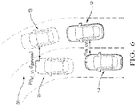
- a side collision risk estimation system 10 for a host vehicle 12 is shown.
- the side collision risk estimation system 10 is configured to evaluate a side collision risk between the host vehicle 12 and a target vehicle 14 succeeding the host vehicle 12 in the other side of the road line adjacent to the host vehicle 12.
- the adjacent road line is the road line that separates the lane of the target vehicle 14 to the host vehicle 12.
- the system 10 comprises a speed sensor 16 configured to capture the current speed V hv of the host vehicle 12, a road line markers detector unit 18 configured to capture road line markers on the path of the host vehicle 12; a movement sensor unit 20 configured to capture the direction of the host vehicle 12; and an object detector unit 22 configured to detect a target vehicle 14 in the neighboring of the host vehicle 12.
- the road line markers detector unit 18 may comprise a front vision detector and a rear vision detector such that the system 10 may evaluate the heading of the adjacent road line ahead the host vehicle 12 and also the heading of the adjacent road line behind the host vehicle 12. In other words, the system 10 may estimate or predict the heading of the adjacent road line ahead the host vehicle 12 and also the heading of the adjacent road line behind the host vehicle 12.
- the adjacent road line markers arranged on the side of the host vehicle and the adjacent road line markers arranged behind the host vehicle 12, i.e. behind the detection zone of the front vision detector, are a symmetrical expansion around the origin point of the adjacent road line markers ahead the host vehicle 12. More precisely, the symmetrical expansion is an axial symmetry around the axis orthogonal to the tangent line of the curved road line at the origin point of detection.
- the adjacent road line markers ahead the target vehicle 14 are a symmetrical expansion around the origin point of the detected adjacent road line markers ahead the host vehicle 12, such that the system 10 may comprise only one front vision detector, as a single front camera arranged on the front windshield of the host vehicle 12, or elsewhere, that only captures the front road line markers.
- the system 10 comprises a controller 24, or a processor, configured to estimate the heading of the road ahead the host vehicle 12 from the adjacent road line markers ahead the host vehicle 12 and also to estimate the heading of the road ahead the target vehicle 14 from the adjacent road line markers ahead the host vehicle 12.
- the movement sensor unit 20 of the host vehicle 12 may be a two dimensions or three dimensions accelerometer, or alternatively a gyroscope, that is able to sense the direction of the host vehicle 12.
- a gyroscope that is able to sense the direction of the host vehicle 12.
- the object detector unit 22 may be a camera, a radar sensor or a Lidar sensor.
- the object detector unit 22 may comprise two rear corner side radar sensors or rear side Lidar sensors arranged on the right and on the left side rear corner of the host vehicle 12 such that a target vehicle 14 approaching the host vehicle 12 and traveling toward the host vehicle 12, in the same direction than the host vehicle 12, and in the other side of a road line adjacent to the host vehicle 12 may be easily detected, located and speed evaluated.
- a 90° field of view for each rear corner side radar may be enough to cover the desired rear side portion of the host vehicle 12.
- the system 10 comprises the controller 24 in communication with the speed sensor 16, the road line markers detector unit 18, the movement sensor unit 20, and the object detector unit 22.
- the controller 24 comprises a heading of a road line estimation block 26, such that by means of the road line markers detector unit 18, the controller 24 is configured to estimate the heading of the adjacent road line ahead the host vehicle 12 and extrapolate the heading of the adjacent road line ahead the host vehicle 12 to estimate the heading of the adjacent road line ahead the target vehicle 14.
- the controller 24 comprises a heading of a vehicle estimation block 28, such that by means of the movement sensor unit 20 of the host vehicle 12, the controller 24 is able to estimate a heading of the host vehicle 12.
- the heading of a vehicle estimation block 28 of the controller 24 is configured to estimate the relative heading of the target vehicle 14 to the host vehicle 12.
- the controller 24 comprises a compensated heading of vehicle estimation block 30 configured to calculate a compensated heading of the host vehicle 12 by subtracting the estimated heading of the adjacent road line ahead the host vehicle 12 to the estimated heading of the host vehicle 12.
- the controller 24 comprises a vehicle lateral change position block 32 configured to calculate a predicted lateral change position of the host vehicle 12 over the time relative to the current position of the host vehicle 12 by combining the current speed V hv of the host vehicle 12, and the compensated heading of the host vehicle 12.
- the usage of the compensated heading of the host vehicle 12 provides a great accuracy on estimation of the particular timing from when the host vehicle 12 may leave its lane by crossing the adjacent road line in a curved road such that side collision risk estimation with the target vehicle 14 increased.
- the heading of a vehicle estimation block of the controller 24 is configured to estimate a relative heading of the target vehicle 14 to the host vehicle 12.
- the controller 24 is also configured to estimate the current speed of the target vehicle 14.
- the controller 24 comprises a lateral distance estimation block 34 such that by means of the object detector unit 22 of the host vehicle 12, the controller 24 is configured to estimate the current lateral distance between the host vehicle 12 and the target vehicle 14. The determination or estimation of the cited parameters of the target vehicle 14 relative to the host vehicle 12 are necessary to monitor the behavior of the target vehicle 14 relative to the behavior of the host vehicle 12.
- the compensated heading of vehicle estimation block 30 of the controller 24 is configured to calculate a compensated relative heading of the target vehicle 14 by subtracting the estimated heading of the adjacent road line ahead the target vehicle 14 to the estimated relative heading of a target vehicle 14.
- the vehicle lateral change position block 32 of the controller 24 is configured to calculate a predicted lateral change position of the target vehicle 14 over the time relative to the current position of the target vehicle 14 by combining the current speed V tv of the target vehicle 14, and the compensated relative heading of the target vehicle 14.
- the usage of the compensated relative heading of the target vehicle 14 provides a great accuracy on estimation of the particular timing from when the target vehicle 14 may leave its lane by crossing the adjacent road line in a curved road such that side collision risk estimation with the host 12 vehicle increased.
- the lateral distance estimation block 34 of the controller 24 is configured to calculate the predicted lateral distance over the time between the host vehicle 12 and the target vehicle 14 by combining the current lateral distance with the predicted lateral change position of the host vehicle 12 over the time, and with the predicted lateral change position of the target vehicle 14 over the time.
- the controller 24 is configured to evaluate side collision risk over the time.
- the controller 24 comprises a side collision risk estimation block 36 configured to assess the risk of collision and to trigger a side collision warning and some advanced driver-assistance systems (ADAS) if some predetermined threshold(s) is(are) satisfied.
- Predetermined threshold such as time to collision threshold may be dependent on reaction time of ADAS system, or expected human reaction time as manual vehicle braking reaction time that may reduce collision risk.
- a longitudinal axis L hv of the host vehicle is defined, said host vehicle longitudinal axis L hv corresponding of the longitudinal axis L hv of the host vehicle 12, i.e. the axis according to which the host vehicle 12 extends from the rear to the front and globally parallel to a flat road on which the host vehicle 12 is travelling.
- a transversal axis T hv of the host vehicle 12 is also defined, said host vehicle transversal axis T hv being orthogonal to the host vehicle longitudinal axis L hv and also globally parallel to the flat road on which the host vehicle 12 is travelling.
- the host vehicle transversal axis T hv is the axis according to which the host vehicle 12 extends from the left to the right.
- the target vehicle 14 succeeds the host vehicle 12 in the other side of the road line 38 adjacent to the host vehicle 12.
- the road line markers detector unit 18, i.e. the front camera arranged on the front windshield of the host vehicle 12, is capturing images of the road 40 ahead the host vehicle 12. More particularly, the front camera is capturing images of the adjacent road line markers 42, 44 ahead the host vehicle 12 such that the controller 24 is able to calculate the heading ⁇ rh of the adjacent road line 38a ahead the host vehicle 12.
- the heading ⁇ rh of the adjacent road line 38a ahead the host vehicle 12 detected by the front camera i.e. the angle ⁇ rh of the adjacent road line relative to the host vehicle longitudinal axis L hv
- ⁇ rh d xh tan ⁇ 1 a 1 + a 2 * 2 d xh + a 3 * 3 d 2 xh
- the coefficients a1, a2 and a3 are determined by the heading of a road line estimation block 26 of the controller 24.
- the adjacent road line markers 46, 48 ahead the target vehicle 14 are a symmetrical expansion around the origin point O of the detected adjacent road line markers 42, 44 ahead the host vehicle 12.
- the adjacent road line markers 46, 48 ahead the target vehicle 14 are the symmetrics of the road line markers 42, 44 ahead the host vehicle 12 according to an axial symmetry around the axis orthogonal to the tangent line of the curved road line at the origin point of detection of the road line markers 42, 44 ahead the host vehicle 12.
- the adjacent road line markers 46, 48 ahead the target vehicle 14 are a symmetrical expansion around the origin point O of the detection of the adjacent road line markers 42, 44 ahead the host vehicle 12, the heading ⁇ rt of the adjacent road line 38b ahead the target vehicle 14, at a distance d xt from the origin point O, i.e.
- the target vehicle 14 succeeds the host vehicle 12 in the other side of the road line 38 adjacent to the host vehicle 12.
- the object detector unit 22 i.e. the rear left corner side radar of the host vehicle 12, is detecting the target vehicle 14.
- a ghost target vehicle 15 is shown at a predicted position of the target vehicle 14 at a preview timing t preview following the current position of the target vehicle 14.
- a longitudinal axis L tv of the target vehicle 14 is defined, said target vehicle longitudinal axis L tv corresponding of the longitudinal axis L tv of the target vehicle 14, i.e. the axis according to which the target vehicle 14 extends from the rear to the front and globally parallel to a flat road on which the target vehicle 14 is travelling.
- a transversal axis T tv of the target vehicle 14 is also defined, said target vehicle transversal axis T tv being orthogonal to the target vehicle longitudinal axis L tv and also globally parallel to the flat road on which the target vehicle 14 is travelling.
- the target vehicle transversal axis T tv is the axis according to which the target vehicle 14 extends from the left to the right.
- the host vehicle 12 is estimated the current speed V tv of the target vehicle 14, the current distance d ht between the host vehicle 12 and the target vehicle 14, and the relative heading ⁇ tv of the target vehicle 14 to the host vehicle 12, i.e. relative to the longitudinal axis L hv of the host vehicle 12.
- ⁇ rt d long tan ⁇ 1 a 1 + a 2 * 2 d long + a 3 ⁇ 3 d 2 long
- the predicted lateral change position d lat_t (t) of the target vehicle 14 over the time relative to the current position of the target vehicle 14 is evaluated.
- the estimated lateral position deviation of the target vehicle 14 over the time according to the current transversal axis T tv of the target vehicle14 is evaluated.
- the predicted lateral change position d lat_t (t) of the target vehicle 14 over the time is calculated by combining the current speed V tv of the target vehicle 14 and the compensated relative heading ⁇ tv_comp of the target vehicle 14, as equation 5:
- d lat_t t V tv ⁇ sin ⁇ tv ⁇ ⁇ rt d long ⁇ t
- FIG 5 the host vehicle 12 traveling in its lane is shown.
- a ghost host vehicle 13 is shown at a predicted position of the host vehicle 12 at the preview time t preview following the current position of the host vehicle 12.
- the controller 24 is configured to calculate the estimated lateral position deviation of the host vehicle 12 over the time according to the current transversal axis T hv of the host vehicle12.
- the predicted lateral change position d lat_h (t) of the host vehicle 12 over the time is then calculated using a constant yaw rate model to calculate the lateral movement of the host vehicle 12. Accordingly, the calculation is done iteratively and the desired predetermined time, i.e. the preview time t preview , is divided into segments equaling the length of sampling interval of the side collision risk estimation system.
- the length of sampling interval is the time duration between two samplings. In other words, the calculation is done according to a sampling acquisition time of the movement sensor unit 20, and of the road line markers detector unit 18 by the controller 24 of the side collision risk estimation system 10.
- the predicted heading ⁇ rh of the adjacent road line ahead the host vehicle 12 is sampled by the system 10, such that the plurality of adjacent road lines markers captured by the front vision detector of the host vehicle 12 are sampled into a plurality of successive single predicted heading samples ⁇ rh_1 , ⁇ rh_2 ,... ⁇ rh_tpreview/dt of the adjacent road line 38a ahead the current position of the host vehicle 12.
- the predicted lateral change position d lat_h (t) of the host vehicle 12 over the time relative to the current position of the host vehicle 12 is evaluated.
- the estimated lateral position deviation of the host vehicle 12 over the time according to the current transversal axis T hv of the host vehicle12 is evaluated.
- the target vehicle 14 at a current position succeeding the host vehicle 12 at a current position in the other side of the road line 38 adjacent to the host vehicle 12 is shown.
- the ghost target vehicle 15 at the positon at the preview time t preview and the ghost host vehicle 13 at the same preview time t preview are shown.
- the controller 24 of the side collision risk estimation system 10 is configured to evaluate the current lateral distance d lat_cvh between the host vehicle 12 and the target vehicle 14.
- said current lateral distance d lat_cvh is representative of the shortest measured distance from the host vehicle 12 to the target vehicle 12 while the target vehicle 12 is travelling in the other side of the road line 38 adjacent to the host vehicle 12.
- the system 10 is configured to calculate the predicted lateral distance Pd lat_vh over the time t between the host vehicle 12 and the target vehicle 14 by combining the current lateral distance d lat_cvh with the predicted lateral change position d lat_h (t) of the host vehicle 12 over the time t, and with the predicted lateral change position d lat_t (t) of the target vehicle 14 over the time using equation 15:
- Pd lat _ vh t d lat _ cvh + d lat _ t t + d lat _ h t
- the predicted lateral change position d lat_h (t) of the host vehicle 12 over the time t, and the predicted lateral change position d lat_t (t) of the target vehicle 14 over the time may be a positive value or a negative value as dependent on the transversal direction of the lateral change position of the host vehicle 12 and of the target vehicle 14.
- the predicted lateral distance Pd lat_vh (t preview ) between the host vehicle 12 and the target vehicle 14 is estimated from equation 16 as being:
- Pd lat _ vh t preview d lat _ cvh + d lat _ t t preview + d lat _ h t preview
- the collision risk estimation may be set up by setting up a predicted safety lateral distance Pdlat_vh threshold in combination to a the time to collision threshold from which a driver of the host vehicle could not be generally able to avoid the collision such that ADAS system is taking over the control of the host vehicle to limit the collision risk.
- a method 100 of operating the side collision risk estimation system 10 to estimate a side collision risk with a target vehicle 14 succeeding the host vehicle 12 in the other side of a road line 38 adjacent to the host vehicle 12 comprises some steps for estimating predicted path over the time of the host vehicle 12.
- the first steps comprises a step of estimating 110 the current speed V hv of the host vehicle 12, a step of estimating 120 the heading ⁇ rh of the adjacent road line ahead the host vehicle 12; and a step of estimating 130 the heading ⁇ hv of the host vehicle 12.
- the estimation of the heading ⁇ hv of the host vehicle 12 has to be correlated with the heading of the road ahead the host vehicle 12.
- the method comprises as step of calculating 140 a compensated heading ⁇ hv_comp of the host vehicle 12 by combining the estimated heading ⁇ rh of the adjacent road line ahead the host vehicle 12 with the estimated heading ⁇ hv of a host vehicle 12.
- the step of calculating 14 the compensated heading ⁇ hv_comp of the host vehicle 12 is a step of subtracting the estimated heading ⁇ rh of the adjacent road line ahead the host vehicle 12 to the estimated heading ⁇ hv of a host vehicle 12.
- the method comprises a step of calculating 150 the predicted lateral change position d lat_h (t) of the host vehicle 12 over the time t relative to the current position of the host vehicle 12 by combining the current speed V hv of the host vehicle 12, and the compensated heading ⁇ hv_comp of the host vehicle 12.
- the predicted lateral change position d lat_h (t) of the host vehicle 12 over the time relative to the current position of the host vehicle 12 is taking into account the lateral change of the host vehicle 12 regarding the temporal change direction of the host vehicle 12 provided by its movement sensor unit 20 and the heading ⁇ rh of the adjacent road line 38a ahead the host vehicle 12, such that it will be possible to predict that the host vehicle 12 may leave its road lane as crossing the adjacent road line markers 42, 44.
- the method 100 comprises steps relative to the target vehicle 14 in order to evaluate the collision risk between the host vehicle 12 and the target vehicle 14. At first, the method comprises some steps for estimating predicted path over the time of the target vehicle 14.
- the first steps comprises a step of estimating 210 the current speed V tv of the target vehicle 14; a step of estimating 220 the heading ⁇ rt of the adjacent road line 38b ahead the target vehicle 14; and a step of estimating 230 the relative heading ⁇ tv of the target vehicle 14 to the host vehicle 12.
- the estimation of the relative heading ⁇ tv of the target vehicle 14 has to be correlated with the heading ⁇ rt of adjacent the road line ahead the target vehicle 14.
- the method comprises as step of calculating 240 a compensated relative heading ⁇ tv_comp of the target vehicle 14 by subtracting the estimated heading ⁇ rt of the adjacent road line 38b ahead the target vehicle 14 to the estimated relative heading ⁇ tv of the target vehicle 14.
- the method comprises a step of calculating 250 the predicted lateral change position d lat_t (t) of the target vehicle 14 over the time relative to the current position of the target vehicle 14 by combining the current speed V tv of the target vehicle 14, and the compensated relative heading ⁇ tv_comp of the target vehicle 14.
- the method comprises a step of estimating 310 the current lateral distance between the host vehicle 12 and the target vehicle 14. Such estimation is used as a starting point in time to evaluate a predicted lateral distance over the time between the host vehicle 12 and the target vehicle 14.
- the method comprises a step of calculating 320 a predicted lateral distance over the time between the host vehicle 12 and the target vehicle 14 by combining the current lateral distance with the predicted lateral change position d lat_h (t) of the host vehicle 12 over the time, and with the predicted lateral change position d lat_t (t) of the target vehicle 14 over the time.
- the step of calculating 320 the predicted lateral distance over the time between the host vehicle 12 and the target vehicle 14 comprises a step of adding or subtracting, depending on the transversal direction of the lateral change position of the host vehicle 12 and of the target vehicle 14, the predicted lateral change position d lat_h (t) of the host vehicle 12 over the time, and the predicted lateral change position d lat_t (t) of the target vehicle 14 over the time, to the current lateral distance between the host vehicle 12 and the target vehicle 14.
- the method 100 comprises a step of evaluating 330 a side collision risk over the time from the predicted lateral distance between the host vehicle 12 and the target vehicle 14.
- the evaluation generally comprises one or more predetermined threshold(s).
- a predetermined threshold such as time to collision threshold relative to reaction time of ADAS system, or relative to expected human reaction time as manual vehicle braking reaction time that may be used for that evaluation step.
- the step of estimating 220 the heading ⁇ rt of the adjacent road line 38b ahead the target vehicle 14 can preliminary comprises a step of assigning 120 to the adjacent road line markers 46, 48 ahead the target vehicle 14 a symmetrical expansion around the origin point O of detection of the adjacent road line markers 42, 44 ahead the host vehicle 12.
- the step of estimating 220 the heading ⁇ rt of the adjacent road line 38b ahead the target vehicle 14 can comprise a step of detecting road line markers 42, 44 only ahead the host vehicle 12.
- the system 10 includes a first device that includes one or more instances of the controller 24, a memory 25, and one or more instances of a program stored in the memory 25.
- the one or more programs include instructions for performing the method 100.
- the system 10 also includes or consists of a non-transitory computer-readable storage medium comprising one or more programs for execution by one or more controller 24 or processor of the first device, the one or more programs including instructions which, when executed by the one or more controller 24 or processor, cause the first device to perform the method 100.
Landscapes
- Engineering & Computer Science (AREA)
- Transportation (AREA)
- Mechanical Engineering (AREA)
- Automation & Control Theory (AREA)
- Physics & Mathematics (AREA)
- Mathematical Physics (AREA)
- Chemical & Material Sciences (AREA)
- Combustion & Propulsion (AREA)
- Traffic Control Systems (AREA)
Claims (10)
- System (10) zur Abschätzung des Seitenkollisionsrisikos für ein Host-Fahrzeug (12), wobei das System umfassteinen Geschwindigkeitssensor (16), der so konfiguriert ist, dass er die aktuelle Geschwindigkeit (Vhv) des Host-Fahrzeugs (12) erfasst;eine Fahrbahnmarkierungs-Detektoreinheit (18), die so konfiguriert ist, dass sie Fahrbahnmarkierungen (42, 44) auf dem Weg des Host-Fahrzeugs (12) erfasst;eine Bewegungssensoreinheit (20), die so konfiguriert ist, dass sie die Richtung des Host-Fahrzeugs (12) erfasst;eine Objekterfassungseinheit (22), die so konfiguriert ist, dass sie ein Zielfahrzeug (14) erfasst;ein Steuergerät (24), das mit dem Geschwindigkeitssensor (16), der Fahrbahnmarkierungs-Detektoreinheit (18), der Bewegungssensoreinheit (20) und der Objekterfassungseinheit (22) in Verbindung steht, wobei das Steuergerät (24) so konfiguriert ist, dass es:die aktuelle Geschwindigkeit (Vhv) des Host-Fahrzeugs (12) mit Hilfe des Geschwindigkeitssensors (16) schätzt;einen Kurs (ϕrh) der benachbarten Straßentrasse (38a) vor dem Host-Fahrzeug (12) mit Hilfe der Fahrbahnmarkierungs-Detektoreinheit (18) schätzt; undeinen Kurs (αhv) des Host-Fahrzeugs (12) mit Hilfe der Bewegungssensoreinheit (20) schätzt;dadurch gekennzeichnet, dass das Steuergerät (24) ferner so konfiguriert ist, dass es:einen kompensierten Kurs (αhv_comp) des Host-Fahrzeugs (12) berechnet, indem es den geschätzten Kurs (ϕrh) der benachbarten Straßentrasse (38a) vor dem Host-Fahrzeug (12) von dem geschätzten Kurs (αhv) des Host-Fahrzeugs (12) subtrahiert;eine vorhergesagte seitliche Positionsänderung (dlat_h(t)) des Host-Fahrzeugs (12) über die Zeit relativ zu der aktuellen Position des Host-Fahrzeugs (12) durch Kombinieren der aktuellen Geschwindigkeit (Vhv) des Host-Fahrzeugs (12) und des kompensierten Kurses (αhv_comp) des Host-Fahrzeugs (12) berechnet;einen relativen Kurs (αtv) des Zielfahrzeugs (14) zum Host-Fahrzeug (12) schätzt, die aktuelle Geschwindigkeit (Vtv) des Zielfahrzeugs (14) schätzt und den aktuellen seitlichen Abstand zwischen dem Host-Fahrzeug (12) und dem Zielfahrzeug (14) mit Hilfe der Objekterfassungseinheit (22) schätzt;den Kurs (ϕrt) der benachbarten Straßentrasse (38b) vor dem Zielfahrzeug (14) mit Hilfe der Fahrbahnmarkierungs-Detektoreinheit (18) schätzt;einen kompensierten relativen Kurs (αtv_comp) des Zielfahrzeugs (14) durch Subtraktion des geschätzten Kurses (ϕrt) der benachbarten Straßentrasse (38b) vor dem Zielfahrzeug (14) von dem geschätzten relativen Kurs (αtv) des Zielfahrzeugs (14) berechnet;eine vorhergesagte seitliche Positionsänderung (dlat_t(t)) des Zielfahrzeugs (14) über die Zeit relativ zu der aktuellen Position des Zielfahrzeugs (14) durch Kombinieren der aktuellen Geschwindigkeit (Vtv) des Zielfahrzeugs (14) und des kompensierten relativen Kurses (αtv_comp) des Zielfahrzeugs (14) berechnet;den vorhergesagten seitlichen Abstand über die Zeit zwischen dem Host-Fahrzeug (12) und dem Zielfahrzeug (14) durch Kombinieren des aktuellen seitlichen Abstands mit der vorhergesagten seitlichen Positionsänderung (dlat_h(t)) des Host-Fahrzeugs (12) über die Zeit und mit der vorhergesagten seitlichen Positionsänderung (dlat_t(t)) des Zielfahrzeugs (14) über die Zeit berechnet;das Risiko einer seitlichen Kollision über die Zeit anhand des vorhergesagten seitlichen Abstands zwischen dem Host-Fahrzeug (12) und dem Zielfahrzeug (14) abschätzt.
- System (10) nach Anspruch 1, wobei das Steuergerät (24) so konfiguriert ist, dass es den Kurs (ϕrt) der benachbarten Straßentrasse (38b) vor dem Zielfahrzeug (14) schätzt, indem es den benachbarten Fahrbahnmarkierungen (46, 48) vor dem Zielfahrzeug (14) eine symmetrische Ausdehnung um den Ausgangspunkt (O) der Erfassung der benachbarten Fahrbahnmarkierungen (42, 44) vor dem Host-Fahrzeug (12) zuweist.
- System (10) nach Anspruch 2, wobei die Fahrbahnmarkierungs-Detektoreinheit (18) einen Einzelbilddetektor enthält, der so konfiguriert ist, dass er Fahrbahnmarkierungen (42, 44) vor dem Host-Fahrzeug (12) erfasst.
- Host-Fahrzeug (12), das das System (10) nach einem der vorhergehenden Ansprüche umfasst.
- Host-Fahrzeug (12) nach dem vorhergehenden Anspruch, wobeidie Fahrbahnmarkierungs-Detektoreinheit (18) mindestens eine Frontkamera umfasst, die so konfiguriert ist, dass sie die vorderen Fahrbahnmarkierungen vor dem Host-Fahrzeug (12) erfasst;die Bewegungssensoreinheit (20) einen 2D-Beschleunigungsmesser oder ein Gyroskop umfasst, der/das so konfiguriert ist, dass er/sie die Fahrtrichtung des Host-Fahrzeugs (12) erfasst;die Objekterfassungseinheit (22) mindestens einen hinteren Radarsensor oder Lidar-Sensor umfasst, der vorzugsweise an einer Eckseite des Host-Fahrzeugs (12) angeordnet ist, wobei die Objekterfassungseinheit (22) so konfiguriert ist, dass sie ein Objekt an einer hinteren Seitenposition des Host-Fahrzeugs (12) erfasst.
- Verfahren (100) zum Betreiben des Systems (10) zur Abschätzung des Seitenkollisionsrisikos nach einem der Ansprüche 1 bis 3, um ein Seitenkollisionsrisiko mit einem Zielfahrzeug (14) abzuschätzen, das dem Host-Fahrzeug (12) auf der anderen Seite einer Straßentrasse (38) neben dem Host-Fahrzeug (12) folgt, wobei das Verfahren die Schritte umfasst:Schätzen (110) der aktuellen Geschwindigkeit (Vhv) des Host-Fahrzeugs (12);Schätzen (120) des Kurses (ϕrh) der benachbarten Straßentrasse (38a) vor dem Host-Fahrzeug (12); undSchätzen (130) des Kurses (αhv) des Host-Fahrzeugs (12); gekennzeichnet durchBerechnen (140) eines kompensierten Kurses (αhv_comp) des Host-Fahrzeugs (12) durch Subtrahieren des geschätzten Kurses (ϕrh) der benachbarten Straßentrasse (38a) vor dem Host-Fahrzeug (12) von dem geschätzten Kurs (αhv) des Host-Fahrzeugs (12);Berechnen (150) der vorhergesagten seitlichen Positionsänderung (dlat_h(t)) des Host-Fahrzeugs (12) über die Zeit relativ zu der aktuellen Position des Host-Fahrzeugs (12) durch Kombinieren der aktuellen Geschwindigkeit (Vhv) des Host-Fahrzeugs (12) und des kompensierten Kurses (αhv_comp) des Host-Fahrzeugs (12);Schätzen (210) der aktuellen Geschwindigkeit (Vtv) des Zielfahrzeugs (14);Schätzen (220) des Kurses (ϕrt) der benachbarten Straßentrasse (38b) vor dem Zielfahrzeug (14);Schätzen (230) des relativen Kurses (αtv) des Zielfahrzeugs (14) zum Host-Fahrzeug (12);Berechnen (240) eines kompensierten relativen Kurses (αtv_comp) des Zielfahrzeugs (14) durch Subtrahieren des geschätzten Kurses (ϕrt) der benachbarten Straßentrasse (38b) vor dem Zielfahrzeug (14) von dem geschätzten relativen Kurs (αtv) des Zielfahrzeugs (14);Berechnen (250) der vorhergesagten seitlichen Positionsänderung (dlat_t(t)) des Zielfahrzeugs (14) über die Zeit relativ zu der aktuellen Position des Zielfahrzeugs durch Kombinieren der aktuellen Geschwindigkeit (Vtv) des Zielfahrzeugs (14) und des kompensierten relativen Kurses (αtv_comp) des Zielfahrzeugs (14);Schätzen (310) des aktuellen seitlichen Abstands zwischen dem Host-Fahrzeug (12) und dem Zielfahrzeug (14);Berechnen (320) eines vorhergesagten seitlichen Abstands über die Zeit zwischen dem Host-Fahrzeug (12) und dem Zielfahrzeug (14) durch Kombinieren des aktuellen seitlichen Abstands mit der vorhergesagten seitlichen Positionsänderung (dlat_h(t)) des Host-Fahrzeugs (12) über die Zeit und mit der vorhergesagten seitlichen Positionsänderung (dlat_t(t)) des Zielfahrzeugs (14) über die Zeit;Abschätzen (330) des Seitenkollisionsrisikos über die Zeit anhand des vorhergesagten seitlichen Abstands zwischen dem Host-Fahrzeug (12) und dem Zielfahrzeug (14).
- Verfahren (100) nach dem vorhergehenden Anspruch, wobei der Schritt des Schätzens (220) des Kurses (ϕrt) der benachbarten Straßentrasse (38b) vor dem Zielfahrzeug (14) weiterhin vorläufig den Schritt umfasst:
Zuordnen (120) einer symmetrischen Ausdehnung um den Ausgangspunkt (O) der Erfassung der benachbarten Fahrbahnmarkierungen (42, 44) vor dem Host-Fahrzeug (12) zu den benachbarten Fahrbahnmarkierungen (46, 48) vor dem Zielfahrzeug (14). - Verfahren (100) nach Anspruch 7, wobei der Schritt des Schätzens (220) des Kurses (ϕrt) der benachbarten Straßentrasse (38b) vor dem Zielfahrzeug (14) einen Schritt des Erfassens von Fahrbahnmarkierungen (42, 44) nur vor dem Host-Fahrzeug (12) umfasst.
- Erste Vorrichtung, die umfasst:einen Geschwindigkeitssensor (16), der so konfiguriert ist, dass er eine aktuelle Geschwindigkeit (Vhv) eines Host-Fahrzeugs (12) erfasst;eine Fahrbahnmarkierungs-Detektoreinheit (18), die so konfiguriert ist, dass sie Fahrbahnmarkierungen (42, 44) auf einem Weg des Host-Fahrzeugs (12) erfasst;eine Bewegungssensoreinheit (20), die so konfiguriert ist, dass sie eine Richtung des Host-Fahrzeugs (12) erfasst;eine Objekterfassungseinheit (22), die so konfiguriert ist, dass sie ein Zielfahrzeug (14) erfasst;einen oder mehrere Prozessoren (24);Speicher (25); und ein oder mehrere Programme, die in dem Speicher (25) gespeichert sind, wobei das eine oder die mehreren Programme Anweisungen zur Durchführung des Verfahrens nach den Ansprüchen 6 bis 8 enthält/enthalten.
- Nicht-transitorisches computerlesbares Speichermedium (25), das ein oder mehrere Programme zur Ausführung durch einen oder mehrere Prozessoren (24) einer ersten Vorrichtung umfasst, wobei die erste Vorrichtung umfasst: einen Geschwindigkeitssensor (16), der so konfiguriert ist, dass er eine aktuelle Geschwindigkeit (Vhv) eines Host-Fahrzeugs (12) erfasst; eine Fahrbahnmarkierungs-Detektoreinheit (18), die so konfiguriert ist, dass sie Fahrbahnmarkierungen (42, 44) auf einem Weg des Host-Fahrzeugs (12) erfasst; eine Bewegungssensoreinheit (20), die so konfiguriert ist, dass sie eine Richtung des Host-Fahrzeugs (12) erfasst; und eine Objekterfassungseinheit (22), die so konfiguriert ist, dass sie ein Zielfahrzeug (14) erfasst, wobei das eine oder die mehreren Programme Befehle enthalten, die, wenn sie von dem einen oder den mehreren Prozessoren (24) ausgeführt werden, die erste Vorrichtung veranlassen, das Verfahren nach den Ansprüchen 6 bis 8 durchzuführen.
Priority Applications (3)
| Application Number | Priority Date | Filing Date | Title |
|---|---|---|---|
| EP19160451.1A EP3705384B1 (de) | 2019-03-04 | 2019-03-04 | Seitenkollisionsrisikoschätzungssystem für ein fahrzeug |
| CN202010123645.XA CN111645679B (zh) | 2019-03-04 | 2020-02-27 | 用于车辆的侧面碰撞风险估计系统 |
| US16/807,513 US11498556B2 (en) | 2019-03-04 | 2020-03-03 | Side collision risk estimation system for a vehicle |
Applications Claiming Priority (1)
| Application Number | Priority Date | Filing Date | Title |
|---|---|---|---|
| EP19160451.1A EP3705384B1 (de) | 2019-03-04 | 2019-03-04 | Seitenkollisionsrisikoschätzungssystem für ein fahrzeug |
Publications (2)
| Publication Number | Publication Date |
|---|---|
| EP3705384A1 EP3705384A1 (de) | 2020-09-09 |
| EP3705384B1 true EP3705384B1 (de) | 2021-12-22 |
Family
ID=65686714
Family Applications (1)
| Application Number | Title | Priority Date | Filing Date |
|---|---|---|---|
| EP19160451.1A Active EP3705384B1 (de) | 2019-03-04 | 2019-03-04 | Seitenkollisionsrisikoschätzungssystem für ein fahrzeug |
Country Status (3)
| Country | Link |
|---|---|
| US (1) | US11498556B2 (de) |
| EP (1) | EP3705384B1 (de) |
| CN (1) | CN111645679B (de) |
Families Citing this family (6)
| Publication number | Priority date | Publication date | Assignee | Title |
|---|---|---|---|---|
| CN112202890B (zh) * | 2020-09-30 | 2022-03-22 | 腾讯科技(深圳)有限公司 | 车辆驾驶风险的预警方法、装置和计算机设备 |
| CN112519797A (zh) * | 2020-12-10 | 2021-03-19 | 广州小鹏自动驾驶科技有限公司 | 一种车辆安全距离预警方法、预警系统、汽车及存储介质 |
| CN113096441B (zh) * | 2021-03-25 | 2022-08-05 | 北京星云互联科技有限公司 | 一种车辆预警方法、装置、车辆及存储介质 |
| CN115547099A (zh) * | 2021-06-30 | 2022-12-30 | 中兴通讯股份有限公司 | 预警方法、电子设备和计算机可读存储介质 |
| US11851052B2 (en) * | 2022-01-31 | 2023-12-26 | Ford Global Technologies, Llc | Vehicle path verification |
| DE102022204161A1 (de) * | 2022-04-28 | 2023-11-02 | Robert Bosch Gesellschaft mit beschränkter Haftung | Verfahren zum Vermeiden einer Kollision eines Fahrzeugs |
Family Cites Families (16)
| Publication number | Priority date | Publication date | Assignee | Title |
|---|---|---|---|---|
| GB0111979D0 (en) * | 2001-05-17 | 2001-07-04 | Lucas Industries Ltd | Sensing apparatus for vehicles |
| EP2085279B1 (de) * | 2008-01-29 | 2011-05-25 | Ford Global Technologies, LLC | System zur Vorhersage eines Kollisionskurses |
| US8120476B2 (en) * | 2009-07-22 | 2012-02-21 | International Truck Intellectual Property Company, Llc | Digital camera rear-view system |
| US9963127B2 (en) * | 2010-01-15 | 2018-05-08 | Volvo Car Corporation | Collision mitigation system and method for braking a vehicle |
| US8494716B1 (en) * | 2012-06-04 | 2013-07-23 | GM Global Technology Operations LLC | Lane keeping system using rear camera |
| US9908468B2 (en) * | 2016-01-12 | 2018-03-06 | Toyota Motor Engineering & Manufacturing North America, Inc. | Apparatus and method for providing an extended forward collision warning |
| CN106407893B (zh) * | 2016-08-29 | 2019-11-22 | 东软集团股份有限公司 | 一种检测车道线的方法、装置和设备 |
| JP6515898B2 (ja) * | 2016-09-29 | 2019-05-22 | トヨタ自動車株式会社 | 物標レーン関係認識装置 |
| KR101977458B1 (ko) * | 2017-03-06 | 2019-05-10 | 지엠 글로벌 테크놀러지 오퍼레이션스 엘엘씨 | 레이더 센서와 upa 센서를 이용하는 충돌 예측 알고리즘 |
| CN108569289A (zh) * | 2017-05-19 | 2018-09-25 | 浙江工业职业技术学院 | 一种车载雷达及其逼近探测和目标判别方法 |
| EP3422042B1 (de) * | 2017-06-29 | 2020-03-18 | Aptiv Technologies Limited | Verfahren zur bestimmung der ausrichtung eines zielfahrzeugs |
| US10829120B2 (en) * | 2018-06-18 | 2020-11-10 | Valeo Schalter Und Sensoren Gmbh | Proactive safe driving for an automated vehicle |
| KR102496290B1 (ko) * | 2018-07-06 | 2023-02-06 | 현대모비스 주식회사 | 헤딩각 보상 장치 및 방법 |
| US10875531B2 (en) * | 2018-08-08 | 2020-12-29 | Ford Global Technologies, Llc | Vehicle lateral motion control |
| US10829113B2 (en) * | 2018-09-17 | 2020-11-10 | Ford Global Technologies, Llc | Vehicle collision avoidance |
| CN109583151B (zh) * | 2019-02-20 | 2023-07-21 | 阿波罗智能技术(北京)有限公司 | 车辆的行驶轨迹预测方法及装置 |
-
2019
- 2019-03-04 EP EP19160451.1A patent/EP3705384B1/de active Active
-
2020
- 2020-02-27 CN CN202010123645.XA patent/CN111645679B/zh active Active
- 2020-03-03 US US16/807,513 patent/US11498556B2/en active Active
Also Published As
| Publication number | Publication date |
|---|---|
| EP3705384A1 (de) | 2020-09-09 |
| US20200282985A1 (en) | 2020-09-10 |
| CN111645679B (zh) | 2023-06-27 |
| CN111645679A (zh) | 2020-09-11 |
| US11498556B2 (en) | 2022-11-15 |
Similar Documents
| Publication | Publication Date | Title |
|---|---|---|
| EP3705384B1 (de) | Seitenkollisionsrisikoschätzungssystem für ein fahrzeug | |
| JP6005055B2 (ja) | 車両のパーキングアシストシステムにおける駐車軌道を継続的に計算する、検査するおよび/または適応させる方法、コンピュータプログラムおよびパーキングアシストシステム | |
| US9227632B1 (en) | Method of path planning for evasive steering maneuver | |
| US9229453B1 (en) | Unified motion planner for autonomous driving vehicle in avoiding the moving obstacle | |
| US10350999B2 (en) | Vehicle cruise control apparatus and vehicle cruise control method | |
| EP2778007B1 (de) | Verfahren und System zur Beurteilung von anormalem Fahrverhalten von Fahrzeugen auf einer Straße | |
| EP3078515A1 (de) | Kollisionsvermeidung auf basis von vorderradausschaltverfolgung im rückwärtsbetrieb | |
| JP6363516B2 (ja) | 車両の走行制御装置 | |
| CN107004367B (zh) | 车辆的行驶控制装置以及行驶控制方法 | |
| CN110998685B (zh) | 行进障碍检测装置和车辆导航系统 | |
| KR20110132437A (ko) | 차량의 주행 거동을 자동으로 인식하기 위한 방법 및 이러한 방법을 구현한 운전자 지원 시스템 | |
| CN109212572B (zh) | 定位漂移检测方法、装置、设备及计算机可读存储介质 | |
| EP3486132A1 (de) | Fahrzeugsteuerungsvorrichtung | |
| JP2005511374A (ja) | 自動車を自動的に監視するシステム | |
| JP2012089114A (ja) | 障害物認識装置 | |
| US20120316723A1 (en) | method for determining at least one trafficable area in the surroundings of a motor vehicle | |
| KR101249366B1 (ko) | 차선 인식 장치 및 차선 인식 방법 | |
| US20180012083A1 (en) | Demarcation line recognition apparatus | |
| US10878702B2 (en) | Driving support apparatus and driving support method | |
| US20170192433A1 (en) | Method and device for assisting a driver | |
| GB2486814A (en) | Method for assisting a driver of a motor vehicle | |
| KR20170070580A (ko) | Ecu, 상기 ecu를 포함하는 무인 자율 주행 차량, 및 이의 차선 변경 제어 방법 | |
| CN113335311B (zh) | 一种车辆碰撞检测方法、装置、车辆及存储介质 | |
| US11087149B2 (en) | Object detection apparatus | |
| JP2015154337A (ja) | 対象範囲設定装置、および対象範囲設定プログラム |
Legal Events
| Date | Code | Title | Description |
|---|---|---|---|
| PUAI | Public reference made under article 153(3) epc to a published international application that has entered the european phase |
Free format text: ORIGINAL CODE: 0009012 |
|
| STAA | Information on the status of an ep patent application or granted ep patent |
Free format text: STATUS: THE APPLICATION HAS BEEN PUBLISHED |
|
| AK | Designated contracting states |
Kind code of ref document: A1 Designated state(s): AL AT BE BG CH CY CZ DE DK EE ES FI FR GB GR HR HU IE IS IT LI LT LU LV MC MK MT NL NO PL PT RO RS SE SI SK SM TR |
|
| AX | Request for extension of the european patent |
Extension state: BA ME |
|
| STAA | Information on the status of an ep patent application or granted ep patent |
Free format text: STATUS: REQUEST FOR EXAMINATION WAS MADE |
|
| 17P | Request for examination filed |
Effective date: 20210302 |
|
| RBV | Designated contracting states (corrected) |
Designated state(s): AL AT BE BG CH CY CZ DE DK EE ES FI FR GB GR HR HU IE IS IT LI LT LU LV MC MK MT NL NO PL PT RO RS SE SI SK SM TR |
|
| GRAP | Despatch of communication of intention to grant a patent |
Free format text: ORIGINAL CODE: EPIDOSNIGR1 |
|
| STAA | Information on the status of an ep patent application or granted ep patent |
Free format text: STATUS: GRANT OF PATENT IS INTENDED |
|
| INTG | Intention to grant announced |
Effective date: 20210709 |
|
| GRAS | Grant fee paid |
Free format text: ORIGINAL CODE: EPIDOSNIGR3 |
|
| GRAA | (expected) grant |
Free format text: ORIGINAL CODE: 0009210 |
|
| STAA | Information on the status of an ep patent application or granted ep patent |
Free format text: STATUS: THE PATENT HAS BEEN GRANTED |
|
| AK | Designated contracting states |
Kind code of ref document: B1 Designated state(s): AL AT BE BG CH CY CZ DE DK EE ES FI FR GB GR HR HU IE IS IT LI LT LU LV MC MK MT NL NO PL PT RO RS SE SI SK SM TR |
|
| REG | Reference to a national code |
Ref country code: GB Ref legal event code: FG4D |
|
| REG | Reference to a national code |
Ref country code: CH Ref legal event code: EP |
|
| REG | Reference to a national code |
Ref country code: DE Ref legal event code: R096 Ref document number: 602019010176 Country of ref document: DE |
|
| REG | Reference to a national code |
Ref country code: AT Ref legal event code: REF Ref document number: 1456889 Country of ref document: AT Kind code of ref document: T Effective date: 20220115 |
|
| REG | Reference to a national code |
Ref country code: IE Ref legal event code: FG4D |
|
| REG | Reference to a national code |
Ref country code: LT Ref legal event code: MG9D |
|
| PG25 | Lapsed in a contracting state [announced via postgrant information from national office to epo] |
Ref country code: RS Free format text: LAPSE BECAUSE OF FAILURE TO SUBMIT A TRANSLATION OF THE DESCRIPTION OR TO PAY THE FEE WITHIN THE PRESCRIBED TIME-LIMIT Effective date: 20211222 Ref country code: LT Free format text: LAPSE BECAUSE OF FAILURE TO SUBMIT A TRANSLATION OF THE DESCRIPTION OR TO PAY THE FEE WITHIN THE PRESCRIBED TIME-LIMIT Effective date: 20211222 Ref country code: FI Free format text: LAPSE BECAUSE OF FAILURE TO SUBMIT A TRANSLATION OF THE DESCRIPTION OR TO PAY THE FEE WITHIN THE PRESCRIBED TIME-LIMIT Effective date: 20211222 Ref country code: BG Free format text: LAPSE BECAUSE OF FAILURE TO SUBMIT A TRANSLATION OF THE DESCRIPTION OR TO PAY THE FEE WITHIN THE PRESCRIBED TIME-LIMIT Effective date: 20220322 |
|
| REG | Reference to a national code |
Ref country code: NL Ref legal event code: MP Effective date: 20211222 |
|
| REG | Reference to a national code |
Ref country code: AT Ref legal event code: MK05 Ref document number: 1456889 Country of ref document: AT Kind code of ref document: T Effective date: 20211222 |
|
| PG25 | Lapsed in a contracting state [announced via postgrant information from national office to epo] |
Ref country code: SE Free format text: LAPSE BECAUSE OF FAILURE TO SUBMIT A TRANSLATION OF THE DESCRIPTION OR TO PAY THE FEE WITHIN THE PRESCRIBED TIME-LIMIT Effective date: 20211222 Ref country code: NO Free format text: LAPSE BECAUSE OF FAILURE TO SUBMIT A TRANSLATION OF THE DESCRIPTION OR TO PAY THE FEE WITHIN THE PRESCRIBED TIME-LIMIT Effective date: 20220322 Ref country code: LV Free format text: LAPSE BECAUSE OF FAILURE TO SUBMIT A TRANSLATION OF THE DESCRIPTION OR TO PAY THE FEE WITHIN THE PRESCRIBED TIME-LIMIT Effective date: 20211222 Ref country code: HR Free format text: LAPSE BECAUSE OF FAILURE TO SUBMIT A TRANSLATION OF THE DESCRIPTION OR TO PAY THE FEE WITHIN THE PRESCRIBED TIME-LIMIT Effective date: 20211222 Ref country code: GR Free format text: LAPSE BECAUSE OF FAILURE TO SUBMIT A TRANSLATION OF THE DESCRIPTION OR TO PAY THE FEE WITHIN THE PRESCRIBED TIME-LIMIT Effective date: 20220323 |
|
| PG25 | Lapsed in a contracting state [announced via postgrant information from national office to epo] |
Ref country code: NL Free format text: LAPSE BECAUSE OF FAILURE TO SUBMIT A TRANSLATION OF THE DESCRIPTION OR TO PAY THE FEE WITHIN THE PRESCRIBED TIME-LIMIT Effective date: 20211222 |
|
| PG25 | Lapsed in a contracting state [announced via postgrant information from national office to epo] |
Ref country code: SM Free format text: LAPSE BECAUSE OF FAILURE TO SUBMIT A TRANSLATION OF THE DESCRIPTION OR TO PAY THE FEE WITHIN THE PRESCRIBED TIME-LIMIT Effective date: 20211222 Ref country code: SK Free format text: LAPSE BECAUSE OF FAILURE TO SUBMIT A TRANSLATION OF THE DESCRIPTION OR TO PAY THE FEE WITHIN THE PRESCRIBED TIME-LIMIT Effective date: 20211222 Ref country code: RO Free format text: LAPSE BECAUSE OF FAILURE TO SUBMIT A TRANSLATION OF THE DESCRIPTION OR TO PAY THE FEE WITHIN THE PRESCRIBED TIME-LIMIT Effective date: 20211222 Ref country code: PT Free format text: LAPSE BECAUSE OF FAILURE TO SUBMIT A TRANSLATION OF THE DESCRIPTION OR TO PAY THE FEE WITHIN THE PRESCRIBED TIME-LIMIT Effective date: 20220422 Ref country code: ES Free format text: LAPSE BECAUSE OF FAILURE TO SUBMIT A TRANSLATION OF THE DESCRIPTION OR TO PAY THE FEE WITHIN THE PRESCRIBED TIME-LIMIT Effective date: 20211222 Ref country code: EE Free format text: LAPSE BECAUSE OF FAILURE TO SUBMIT A TRANSLATION OF THE DESCRIPTION OR TO PAY THE FEE WITHIN THE PRESCRIBED TIME-LIMIT Effective date: 20211222 Ref country code: CZ Free format text: LAPSE BECAUSE OF FAILURE TO SUBMIT A TRANSLATION OF THE DESCRIPTION OR TO PAY THE FEE WITHIN THE PRESCRIBED TIME-LIMIT Effective date: 20211222 |
|
| PG25 | Lapsed in a contracting state [announced via postgrant information from national office to epo] |
Ref country code: PL Free format text: LAPSE BECAUSE OF FAILURE TO SUBMIT A TRANSLATION OF THE DESCRIPTION OR TO PAY THE FEE WITHIN THE PRESCRIBED TIME-LIMIT Effective date: 20211222 Ref country code: AT Free format text: LAPSE BECAUSE OF FAILURE TO SUBMIT A TRANSLATION OF THE DESCRIPTION OR TO PAY THE FEE WITHIN THE PRESCRIBED TIME-LIMIT Effective date: 20211222 |
|
| REG | Reference to a national code |
Ref country code: DE Ref legal event code: R097 Ref document number: 602019010176 Country of ref document: DE |
|
| PG25 | Lapsed in a contracting state [announced via postgrant information from national office to epo] |
Ref country code: IS Free format text: LAPSE BECAUSE OF FAILURE TO SUBMIT A TRANSLATION OF THE DESCRIPTION OR TO PAY THE FEE WITHIN THE PRESCRIBED TIME-LIMIT Effective date: 20220422 |
|
| PLBE | No opposition filed within time limit |
Free format text: ORIGINAL CODE: 0009261 |
|
| STAA | Information on the status of an ep patent application or granted ep patent |
Free format text: STATUS: NO OPPOSITION FILED WITHIN TIME LIMIT |
|
| PG25 | Lapsed in a contracting state [announced via postgrant information from national office to epo] |
Ref country code: MC Free format text: LAPSE BECAUSE OF FAILURE TO SUBMIT A TRANSLATION OF THE DESCRIPTION OR TO PAY THE FEE WITHIN THE PRESCRIBED TIME-LIMIT Effective date: 20211222 Ref country code: DK Free format text: LAPSE BECAUSE OF FAILURE TO SUBMIT A TRANSLATION OF THE DESCRIPTION OR TO PAY THE FEE WITHIN THE PRESCRIBED TIME-LIMIT Effective date: 20211222 Ref country code: AL Free format text: LAPSE BECAUSE OF FAILURE TO SUBMIT A TRANSLATION OF THE DESCRIPTION OR TO PAY THE FEE WITHIN THE PRESCRIBED TIME-LIMIT Effective date: 20211222 |
|
| REG | Reference to a national code |
Ref country code: CH Ref legal event code: PL |
|
| 26N | No opposition filed |
Effective date: 20220923 |
|
| REG | Reference to a national code |
Ref country code: BE Ref legal event code: MM Effective date: 20220331 |
|
| PG25 | Lapsed in a contracting state [announced via postgrant information from national office to epo] |
Ref country code: LU Free format text: LAPSE BECAUSE OF NON-PAYMENT OF DUE FEES Effective date: 20220304 Ref country code: LI Free format text: LAPSE BECAUSE OF NON-PAYMENT OF DUE FEES Effective date: 20220331 Ref country code: IE Free format text: LAPSE BECAUSE OF NON-PAYMENT OF DUE FEES Effective date: 20220304 Ref country code: CH Free format text: LAPSE BECAUSE OF NON-PAYMENT OF DUE FEES Effective date: 20220331 |
|
| PG25 | Lapsed in a contracting state [announced via postgrant information from national office to epo] |
Ref country code: SI Free format text: LAPSE BECAUSE OF FAILURE TO SUBMIT A TRANSLATION OF THE DESCRIPTION OR TO PAY THE FEE WITHIN THE PRESCRIBED TIME-LIMIT Effective date: 20211222 Ref country code: BE Free format text: LAPSE BECAUSE OF NON-PAYMENT OF DUE FEES Effective date: 20220331 |
|
| PG25 | Lapsed in a contracting state [announced via postgrant information from national office to epo] |
Ref country code: IT Free format text: LAPSE BECAUSE OF FAILURE TO SUBMIT A TRANSLATION OF THE DESCRIPTION OR TO PAY THE FEE WITHIN THE PRESCRIBED TIME-LIMIT Effective date: 20211222 |
|
| P01 | Opt-out of the competence of the unified patent court (upc) registered |
Effective date: 20230424 |
|
| PG25 | Lapsed in a contracting state [announced via postgrant information from national office to epo] |
Ref country code: MK Free format text: LAPSE BECAUSE OF FAILURE TO SUBMIT A TRANSLATION OF THE DESCRIPTION OR TO PAY THE FEE WITHIN THE PRESCRIBED TIME-LIMIT Effective date: 20211222 Ref country code: CY Free format text: LAPSE BECAUSE OF FAILURE TO SUBMIT A TRANSLATION OF THE DESCRIPTION OR TO PAY THE FEE WITHIN THE PRESCRIBED TIME-LIMIT Effective date: 20211222 |
|
| PGFP | Annual fee paid to national office [announced via postgrant information from national office to epo] |
Ref country code: DE Payment date: 20240322 Year of fee payment: 6 Ref country code: GB Payment date: 20240319 Year of fee payment: 6 |
|
| PG25 | Lapsed in a contracting state [announced via postgrant information from national office to epo] |
Ref country code: HU Free format text: LAPSE BECAUSE OF FAILURE TO SUBMIT A TRANSLATION OF THE DESCRIPTION OR TO PAY THE FEE WITHIN THE PRESCRIBED TIME-LIMIT; INVALID AB INITIO Effective date: 20190304 |
|
| PGFP | Annual fee paid to national office [announced via postgrant information from national office to epo] |
Ref country code: FR Payment date: 20240326 Year of fee payment: 6 |