EP3703960B1 - Nutzfahrzeugreifen - Google Patents
Nutzfahrzeugreifen Download PDFInfo
- Publication number
- EP3703960B1 EP3703960B1 EP18748894.5A EP18748894A EP3703960B1 EP 3703960 B1 EP3703960 B1 EP 3703960B1 EP 18748894 A EP18748894 A EP 18748894A EP 3703960 B1 EP3703960 B1 EP 3703960B1
- Authority
- EP
- European Patent Office
- Prior art keywords
- groove
- elevations
- vehicle tyre
- utility vehicle
- circumferential
- Prior art date
- Legal status (The legal status is an assumption and is not a legal conclusion. Google has not performed a legal analysis and makes no representation as to the accuracy of the status listed.)
- Active
Links
Images



Classifications
-
- B—PERFORMING OPERATIONS; TRANSPORTING
- B60—VEHICLES IN GENERAL
- B60C—VEHICLE TYRES; TYRE INFLATION; TYRE CHANGING; CONNECTING VALVES TO INFLATABLE ELASTIC BODIES IN GENERAL; DEVICES OR ARRANGEMENTS RELATED TO TYRES
- B60C11/00—Tyre tread bands; Tread patterns; Anti-skid inserts
- B60C11/03—Tread patterns
- B60C11/0306—Patterns comprising block rows or discontinuous ribs
- B60C11/0309—Patterns comprising block rows or discontinuous ribs further characterised by the groove cross-section
-
- B—PERFORMING OPERATIONS; TRANSPORTING
- B60—VEHICLES IN GENERAL
- B60C—VEHICLE TYRES; TYRE INFLATION; TYRE CHANGING; CONNECTING VALVES TO INFLATABLE ELASTIC BODIES IN GENERAL; DEVICES OR ARRANGEMENTS RELATED TO TYRES
- B60C11/00—Tyre tread bands; Tread patterns; Anti-skid inserts
- B60C11/03—Tread patterns
- B60C11/04—Tread patterns in which the raised area of the pattern consists only of continuous circumferential ribs, e.g. zig-zag
- B60C11/042—Tread patterns in which the raised area of the pattern consists only of continuous circumferential ribs, e.g. zig-zag further characterised by the groove cross-section
-
- B—PERFORMING OPERATIONS; TRANSPORTING
- B60—VEHICLES IN GENERAL
- B60C—VEHICLE TYRES; TYRE INFLATION; TYRE CHANGING; CONNECTING VALVES TO INFLATABLE ELASTIC BODIES IN GENERAL; DEVICES OR ARRANGEMENTS RELATED TO TYRES
- B60C11/00—Tyre tread bands; Tread patterns; Anti-skid inserts
- B60C11/03—Tread patterns
- B60C11/04—Tread patterns in which the raised area of the pattern consists only of continuous circumferential ribs, e.g. zig-zag
- B60C11/042—Tread patterns in which the raised area of the pattern consists only of continuous circumferential ribs, e.g. zig-zag further characterised by the groove cross-section
- B60C11/045—Tread patterns in which the raised area of the pattern consists only of continuous circumferential ribs, e.g. zig-zag further characterised by the groove cross-section the groove walls having a three-dimensional shape
-
- B—PERFORMING OPERATIONS; TRANSPORTING
- B60—VEHICLES IN GENERAL
- B60C—VEHICLE TYRES; TYRE INFLATION; TYRE CHANGING; CONNECTING VALVES TO INFLATABLE ELASTIC BODIES IN GENERAL; DEVICES OR ARRANGEMENTS RELATED TO TYRES
- B60C11/00—Tyre tread bands; Tread patterns; Anti-skid inserts
- B60C11/03—Tread patterns
- B60C11/13—Tread patterns characterised by the groove cross-section, e.g. for buttressing or preventing stone-trapping
- B60C11/1307—Tread patterns characterised by the groove cross-section, e.g. for buttressing or preventing stone-trapping with special features of the groove walls
- B60C11/1315—Tread patterns characterised by the groove cross-section, e.g. for buttressing or preventing stone-trapping with special features of the groove walls having variable inclination angles, e.g. warped groove walls
-
- B—PERFORMING OPERATIONS; TRANSPORTING
- B60—VEHICLES IN GENERAL
- B60C—VEHICLE TYRES; TYRE INFLATION; TYRE CHANGING; CONNECTING VALVES TO INFLATABLE ELASTIC BODIES IN GENERAL; DEVICES OR ARRANGEMENTS RELATED TO TYRES
- B60C11/00—Tyre tread bands; Tread patterns; Anti-skid inserts
- B60C11/03—Tread patterns
- B60C11/04—Tread patterns in which the raised area of the pattern consists only of continuous circumferential ribs, e.g. zig-zag
- B60C11/042—Tread patterns in which the raised area of the pattern consists only of continuous circumferential ribs, e.g. zig-zag further characterised by the groove cross-section
- B60C11/047—Tread patterns in which the raised area of the pattern consists only of continuous circumferential ribs, e.g. zig-zag further characterised by the groove cross-section the groove bottom comprising stone trapping protection elements, e.g. ribs
-
- B—PERFORMING OPERATIONS; TRANSPORTING
- B60—VEHICLES IN GENERAL
- B60C—VEHICLE TYRES; TYRE INFLATION; TYRE CHANGING; CONNECTING VALVES TO INFLATABLE ELASTIC BODIES IN GENERAL; DEVICES OR ARRANGEMENTS RELATED TO TYRES
- B60C11/00—Tyre tread bands; Tread patterns; Anti-skid inserts
- B60C11/03—Tread patterns
- B60C2011/0337—Tread patterns characterised by particular design features of the pattern
- B60C2011/0339—Grooves
- B60C2011/0341—Circumferential grooves
-
- B—PERFORMING OPERATIONS; TRANSPORTING
- B60—VEHICLES IN GENERAL
- B60C—VEHICLE TYRES; TYRE INFLATION; TYRE CHANGING; CONNECTING VALVES TO INFLATABLE ELASTIC BODIES IN GENERAL; DEVICES OR ARRANGEMENTS RELATED TO TYRES
- B60C11/00—Tyre tread bands; Tread patterns; Anti-skid inserts
- B60C11/03—Tread patterns
- B60C11/13—Tread patterns characterised by the groove cross-section, e.g. for buttressing or preventing stone-trapping
- B60C11/1307—Tread patterns characterised by the groove cross-section, e.g. for buttressing or preventing stone-trapping with special features of the groove walls
- B60C2011/1338—Tread patterns characterised by the groove cross-section, e.g. for buttressing or preventing stone-trapping with special features of the groove walls comprising protrusions
-
- B—PERFORMING OPERATIONS; TRANSPORTING
- B60—VEHICLES IN GENERAL
- B60C—VEHICLE TYRES; TYRE INFLATION; TYRE CHANGING; CONNECTING VALVES TO INFLATABLE ELASTIC BODIES IN GENERAL; DEVICES OR ARRANGEMENTS RELATED TO TYRES
- B60C11/00—Tyre tread bands; Tread patterns; Anti-skid inserts
- B60C11/03—Tread patterns
- B60C11/13—Tread patterns characterised by the groove cross-section, e.g. for buttressing or preventing stone-trapping
- B60C11/1353—Tread patterns characterised by the groove cross-section, e.g. for buttressing or preventing stone-trapping with special features of the groove bottom
- B60C2011/1361—Tread patterns characterised by the groove cross-section, e.g. for buttressing or preventing stone-trapping with special features of the groove bottom with protrusions extending from the groove bottom
Definitions
- the invention relates to a commercial vehicle tire with a tread with at least one circumferential groove with a groove base and groove walls, wherein the base elevations distributed over the circumference and centrally acting as stone ejectors are formed with a height and a greater extent in the circumferential direction than in the axial direction, the base elevations either contact the groove walls or have a spacing of up to 4.0 mm therefrom in the axial direction and are delimited in the radial direction by a cover surface with a circumferential surface edge, the cover surface sloping down to the surface edge, the groove walls between the base elevations approaching wall sections and laterally of the base elevations in plan view have convexly curved wall sections and wherein the surface edge of the top surface follows the course of the mutually convexly curved wall sections in such a way that the width of the base elevations relative to their circumferential direction g lying ends decreases.
- a pneumatic vehicle tire is known with a tread with circumferential grooves with groove flanks running in an undulating manner in plan view, the circumferential grooves being symmetrical with respect to the circumferential groove center lines so that the width of the circumferential grooves changes continuously.
- dome-like base elevations which are elongated in the circumferential direction are formed in the region of the widest points of the circumferential grooves.
- the JP 2012 183 962 A discloses a pneumatic vehicle tire with a tread with a central circumferential groove separating two tread ribs from one another and having groove flanks extending in an undulating manner in plan view, the circumferential groove being symmetrical with respect to a circumferential groove center line.
- recesses extending from the tread periphery are formed which open into the circumferential groove.
- the depressions are each composed of a large-volume depression part, which is spaced from the circumferential groove, and a small-volume, single-cut depression part which opens into the circumferential groove. In combination with the circumferential groove, the depressions should ensure low tire road noise, while at the same time the water drainage capacity is not reduced.
- the JP S6 325 107 A a commercial vehicle tire with a tread with a central circumferential groove, at the bottom of the groove acting as stone ejector base elevations are formed.
- the base elevations are designed in the form of hexagons elongated in the circumferential direction and delimited in the radial direction by flat cover surfaces oriented essentially parallel to the tread periphery.
- the base elevations In the axial direction, the base elevations have a width of 25% to 40% of the profile depth and in the radial direction a height of 20% to 60% of the profile depth.
- trapezoidal projections are formed on the groove walls in plan view, which have a height of 20% to 60% of the profile depth in the radial direction.
- a commercial vehicle tire with a tread which has a circumferential groove running in a zigzag shape in plan view, at the base of which the base elevations spaced from the groove walls are formed as stone ejectors.
- the basic elevations have a height of 20% to 60% of the profile depth and a length of, for example, 6.0 mm in the circumferential direction.
- the DE 37 27 050 A1 discloses a further commercial vehicle tire with a tread with a circumferential groove running in a zigzag shape in plan view with base elevations acting as stone ejectors on the groove base.
- the basic elevations have, for example, an extension length of 4.0 mm in the circumferential direction. Further web-like basic elevations run between these basic elevations.
- the invention is therefore based on the object of improving the effectiveness of the base elevations acting as stone ejectors for the reliable ejection of larger stones in a commercial vehicle tire of the type mentioned at the beginning.
- the top surface drops evenly from the height present at the highest point of the respective base elevation to the height of the surface edge, the maximum height of the base elevations in the radial direction being 25% to 60% of the profile depth and that the wall sections of the groove walls that are convexly curved to one another in plan view, in
- the stone ejectors are components of a groove concept or matched to the design of the groove walls.
- the adaptation of the design of the base elevations to the mutually convexly curved wall sections of the groove walls particularly significantly increases the stability of the base elevations and thereby their ability to effectively eject even larger stones.
- the top surfaces of the base elevations sloping in the direction of the groove base "distribute" the forces acting on the base elevations from the trapped stones, thereby reducing the risk of the stones jamming and protecting the base elevations as well as the groove walls and the groove base from damage by stones penetrating into the groove.
- the wall sections of the groove walls which are convexly curved towards one another in the cross section of the circumferential groove also have a supporting, stabilizing effect on the groove walls in the area of the base elevations and also help to improve the effect of the base elevations.
- the base elevations in plan view, have the shape of diamonds elongated in the circumferential direction with rounded corners.
- Such basic elevations interact with the convexly curved wall sections of the groove walls in such a way that the stone-throwing effect is additionally improved.
- the base elevations are also particularly stable due to the diamond shape.
- the base elevations are composed of a base part with a constant height in the radial direction and a dome-like upper part placed on it. It is preferred here if the height of the base part of the base elevations is 35% to 90%, in particular 40% to 80%, of the maximum height of the base elevations. Such a base increases the stability of the basic lift.
- the top surface of the base elevations have a core top surface and an edge top surface encircling this that slopes down towards the surface edge of the top surface, in order to prevent stones from jamming.
- the base elevations are limited exclusively by their top surfaces.
- Such basic elevations preferably have the shape of half an ellipsoid or a part of a half ellipsoid.
- the completely rounded top surfaces of such ellipsoids on the one hand, very effectively prevent stones from jamming and, on the other hand, the base elevations are particularly resistant to any damage caused by stones.
- the basic elevations are particularly stable if, according to a further preferred variant, they have an extension length of 10.0 mm to 35.0 mm, in particular 15.0 mm to 25.0 mm, in the circumferential direction at their longest point.
- Such basic elevations are significantly larger and more stable than conventionally designed "stone ejectors".
- the maximum height of the base elevations is 30% to 55%, preferably at most 50%, of the profile depth. This measure also contributes to the stability of the base elevations and improves the stone-throwing effect in particular through an advantageous interaction with the curved wall sections.
- the base elevations in the axial direction have a width of 5.0 mm to 15.0 mm at their widest point.
- a groove path of the circumferential groove runs which at its narrowest point has a width of 15% to 45%, in particular a maximum of 35%, of the width of the Has circumferential groove on the tread periphery.
- the water drainage properties in the circumferential grooves are advantageously influenced by such groove paths.
- the wall sections which approach one another between the base elevations, delimit projections which protrude into the circumferential groove and are oppositely positioned in pairs, in particular projections of a nose-like configuration.
- projections as part of the mentioned groove concept on the one hand improve the stone-throwing effect on the one hand and on the other hand by interacting with the base elevations.
- the projections also have a supporting, stabilizing effect on the groove walls in the area of the base elevations.
- the wall sections which are convexly curved relative to one another in plan view, are at a distance of 2.0 mm to 4.0 mm from the base elevations at their radially inner ends.
- the groove walls of the circumferential groove run in a wave shape in plan view and with respect to one of the circumferential direction and the plane spanned in the radial direction symmetrically.
- This variant provides another particularly advantageous groove concept with stone ejectors.
- Commercial vehicle tires designed according to the invention are radial type tires, in particular for construction site vehicles, trucks or buses.
- the central circumferential section of a tread shown has four profile positives 1 running in the circumferential direction, which are shown schematically and in a simplified manner and in particular are tread strips or tread block rows designed in a known manner. Profile positives 1 that are adjacent in the axial direction are each separated by a circumferential groove 2 that runs straight in plan view.
- the circumferential grooves 2 are designed to match in the embodiment shown.
- the design of the circumferential grooves 2 is explained below with reference to the in FIGS. 2 to 8 circumferential groove 2 shown.
- the circumferential groove 2 is delimited on the tread periphery by two groove edges 3 which run essentially in the circumferential direction and in the exemplary embodiment shown in plan view, and also by groove walls 4 adjoining the groove edges 3 and a groove base 5.
- the circumferential groove 2 has, at its deepest point, the tread depth T 1 provided for the respective commercial vehicle tire ( Fig. 4 , Fig. 8 ) from 12.0 mm to 26.0 mm and at the tread periphery at its widest point in the axial direction a width B 1 ( Fig. 8 ) of in particular 10.0 mm to 25.0 mm.
- the groove walls 4 have, viewed in cross section, radially outer sections extending in the radial direction, between which the circumferential groove 2 also has the width B 1 .
- Each groove wall 4 delimits and forms a plurality of flat, nose-like projections 6, which follow one another in the circumferential direction and are arranged at regular intervals over the entire extent of the circumferential groove 2, each projection 6 being delimited by a wall section 4a of the respective groove wall 4.
- the projections 6 delimited by wall sections 4a on both groove walls 4 lie opposite one another in pairs and are designed symmetrically with respect to a plane spanned by the circumferential direction and the radial direction and extending through the center of the circumferential groove 2.
- Each projection 6 is additionally defined with respect to a plane spanned by the radial direction and the axial direction, running through the center of the projection 6 and along the plane in FIG Fig. 2 drawn section line IV-IV runs, executed symmetrically.
- the wall sections 4a delimiting the projections 6 are composed of a slightly outwardly curved central wall area 4a I forming the bridge of the nose and two side wall areas 4a II adjoining this and forming the nostrils.
- the middle wall area 4a I of the wall section 4a runs in the aforementioned plane which coincides with the section line IV-IV, viewed in cross section, to the radial direction at an angle ⁇ ( Fig. 4 ) from 10 ° to 30 °.
- the lateral wall areas 4a II of the wall section 4a are preferably flat surfaces which are inclined to the circumferential direction ( Fig. 3 ) and, viewed in cross section, to the radial direction at an angle ⁇ ( Fig. 5 ) run from, for example, 5 ° to 25 °, where ⁇ ⁇ applies.
- crescent-shaped wall sections 4b run in plan view.
- the sickle-shaped wall sections 4b belonging to a groove wall 4 are convexly curved in plan view with respect to the sickle-shaped wall sections 4b belonging to the opposite groove wall 4.
- the wall sections 4b run out along the lateral wall areas 4a II which form the nostrils.
- the wall sections 4b viewed in cross section, are so slightly bent that the wall sections 4b belonging to the different groove walls 4 are also slightly convexly curved to one another in cross section ( Fig. 7, Fig. 8 ).
- a base elevation 7 acting as a stone ejector is formed centrally on the groove base 5 of the circumferential groove 2.
- Each base elevation 7 is therefore located between two pairs of opposing projections 6 directly following one another in the circumferential direction.
- a groove path 2a remains at the groove base 5 of the circumferential groove 2 ( Fig. 3 ), which revolves around all of the base elevations 7 and extends in plan view essentially along two intersecting shafts which have a matching wavelength and are phase-shifted to one another by half the wavelength in the circumferential direction.
- the groove path 2a has, between the middle wall portions 4a I opposed projections 6 in the radial direction of a depth T 2 ( Fig. 4 ) of up to 4.0 mm, in particular up to 3.0 mm. Furthermore, the groove path 2a between these wall areas 4a I at its narrowest point in the axial direction has a width B 2 ( Fig. 4 ) from 15% to 45%, in particular from a maximum of 35%, of the width B 1 ( Fig. 8 ) the circumferential groove 2.
- the width of the groove path 2a is such that the base elevations 7 at the narrowest point of the groove path 2a to the sickle-shaped wall sections 4b in the axial direction a 1 ( Fig. 8 ) from 2.0 mm to 4.0 mm.
- Each base elevation 7 has a greatest extension length l 1 in the circumferential direction ( Fig. 2 ) from 10.0 mm to 35.0 mm, in particular from 15.0 mm to 25.0 mm, which correlates with the distances in the circumferential direction of successive projections 6 assigned to one another in pairs.
- each base elevation 7 has a height h 1 in its central area at its highest point ( Fig. 8 ), which amounts to 25% to 60%, in particular 30% to 55%, and particularly preferably at most 50%, of the profile depth T 1 provided in each case.
- each base elevation 7 has a width b 1 at its widest point ( Fig. 2 ) from 5.0 mm to 15.0 mm.
- Each base elevation 7 is composed of a base part 7a and a dome-like upper part 7b placed on it.
- the base part 7a has a rectangular cross-section and has a height h 2 determined starting from the groove bottom 5 in the radial direction, which corresponds to 35% to 80%, in particular 40% to 60%, of the height h 1 of the base elevation 7 ( Fig. 8 ).
- the dome-like upper part 7b is in the radial direction by a top surface 8 ( Fig. 8 ), which drops from the height h 1 present at the highest point of the base elevation 7 to the edges of the dome-like upper part 7b evenly to the height h 2.
- the top surface 8 is preferably formed by several, in the illustrated embodiment of nine, flat partial top surfaces.
- Figures 9a and 9b show a circumferential groove 2 ', which is a variant of the circumferential groove 2 and differs therefrom by undulating groove edges 3' in plan view and by groove walls 4 'adjoining this and undulating in plan view.
- the groove walls 4 ' preferably run at a constant angle of 5 ° to 30 °, in particular 10 ° to 20 °, to the radial direction.
- the two groove edges 3 'and the two groove walls 4' are each designed symmetrically with respect to a plane spanned by the circumferential direction and the radial direction, the circumferential groove 2 'at the tread periphery having a width B 1 ' at its widest point and a width B 1 'at the narrowest point has a width B 2 '.
- the width B 1 ' is 10.0 mm to 25.0 mm
- the width B 2 ' is 75% to 95% of the width B 1 '.
- the Groove walls 4 ' have wall sections 4'a that are concavely curved to one another in plan view and wall sections 4'b that are convexly curved to one another in plan view alternately in the circumferential direction
- each intermediate space which is located between opposing wall sections 4'b that are convexly curved to one another, there is a central elevation 7 of the first variant ( FIGS. 1 to 8 ) correspondingly designed base elevation 7 'formed with a top surface 8' which, in the exemplary embodiment shown, contacts the groove walls 4 'at their radially inner end regions ( Figure 9b ).
- a groove path preferably remains on the groove base of the circumferential groove 2 ', which path runs around all the base elevations 7' and is at a distance of 2.0 mm to 4.0 mm in the axial direction from the wall sections 4'b. From the groove base of the circumferential groove 2 ', there remain a plurality of between adjacent base elevations 7' extending to the profile depth, in plan view elongated X-like groove base regions 5 'in the circumferential direction.
- Figures 10a and 10b show a circumferential groove 2 ′′, which is a further variant of circumferential groove 2.
- the circumferential groove 2 ′′ differs from the circumferential groove 2 in that the base elevations 7 ′′ are designed differently from its base elevations 7.
- the base elevations 7 ′′ are delimited in the radial direction by a top surface 8 ′′ which has a core cover surface 8 ′′ a aligned parallel to the tread periphery and an edge cover surface 8 ′′ b that encircles it and slopes down to the edge of the base elevation 7 ′′.
- the base elevations 7 ′′ in the area of the core cover surface 8 ′′ a have a height h 3 ( Figure 10c ), which is 25% to 60%, in particular 30% to 55%, and particularly preferably at most 50%, of the profile depth T 1 .
- Figure 10c shows, set the basic raised portions 7 'of a base part 7 "A and one patch on this, trapezoidal in cross-section upper part 7" b together.
- the base part 7 "a extends in the radial direction up to a height h 4, containing 35% to 90 %, in particular 70% to 80%, the height h 3 corresponds to the basic increase 7 "( Fig. 8 ).
- the invention is not restricted to the variant embodiments described.
- the basic elevations can have a shape that deviates from the shape described have, in particular the shape of half ellipsoids or in the form of sections of half ellipsoids.
- the groove walls of the circumferential grooves can also be used without the one in connection with the first variant ( FIGS. 4 to 8 ) mentioned, running in the radial direction radially outer sections.
Landscapes
- Engineering & Computer Science (AREA)
- Mechanical Engineering (AREA)
- Tires In General (AREA)
Description
- Die Erfindung betrifft einen Nutzfahrzeugreifen mit einem Laufstreifen mit zumindest einer Umfangsrille mit einem Rillengrund und Rillenwänden, wobei am Rillengrund über den Umfang verteilt und mittig als Steinauswerfer wirkende Grundanhebungen mit einer Höhe und einer größeren Erstreckung in Umfangsrichtung als in axialer Richtung ausgebildet sind, wobei die Grundanhebungen entweder die Rillenwände kontaktieren oder von diesen in axialer Richtung Abstände von bis zu 4,0 mm aufweisen und in radialer Richtung von einer Deckfläche mit einem umlaufenden Flächenrand begrenzt sind, wobei die Deckfläche zum Flächenrand abfällt, wobei die Rillenwände zwischen den Grundanhebungen sich zueinander annähernde Wandabschnitte und seitlich der Grundanhebungen in Draufsicht zueinander konvex gekrümmte Wandabschnitte aufweisen und wobei der Flächenrand der Deckfläche dem Verlauf der zueinander konvex gekrümmten Wandabschnitte derart folgt, dass die Breite der Grundanhebungen zu ihren in Umfangsrichtung liegenden Enden abnimmt.
- Aus der
US 2012 018 068 A1 ist ein Fahrzeugluftreifen mit einem Laufstreifen mit Umfangsrillen mit in Draufsicht wellenförmig verlaufenden Rillenflanken bekannt, wobei die Umfangsrillen jeweils bezüglich in Umfangsrichtung verlaufenden Rillenmittellinien symmetrisch ausgeführt sind, sodass sich die Breite der Umfangsrillen kontinuierlich ändert. Gemäß einer Ausführungsvariante sind im Bereich der breitesten Stellen der Umfangsrillen in Umfangsrichtung langgestreckte, kuppelartige Grundanhebungen ausgebildet. Beim Fahren auf nassem Untergrund soll von den Umfangsrillen aufgenommenes Wasser über die Rillenflanken aus den Umfangsrillen gut ausgetragen werden können, wobei die kuppelartigen Grundanhebungen einen verstärken Wasserfluss entlang der Rillenflanken bewirken und derart dazu beitragen, Wasser aus den Umfangsrillen herauszufördern. - Die
JP 2012 183 962 A - Ferner offenbart die
JP S6 325 107 A - Aus der
US 4 345 632 A ist ein Nutzfahrzeugreifen mit einem Laufstreifen bekannt, welcher eine in Draufsicht zick-zack-förmig verlaufende Umfangsrille aufweist, an deren Rillengrund von den Rillenwänden beabstandete Grundanhebungen als Steinauswerfer ausgebildet sind. Die Grundanhebungen weisen eine Höhe von 20% bis 60% der Profiltiefe und in Umfangsrichtung eine Länge von beispielsweise 6,0 mm auf. - Die
DE 37 27 050 A1 offenbart einen weiteren Nutzfahrzeugreifen mit einem Laufstreifen mit einer in Draufsicht zick-zack-förmig verlaufenden Umfangsrille mit als Steinauswerfer wirkenden Grundanhebungen am Rillengrund. Die Grundanhebungen haben in Umfangsrichtung beispielsweise eine Erstreckungslänge von 4,0 mm. Zwischen diesen Grundanhebungen verlaufen weitere stegartig gestaltete Grundanhebungen. - Die aus dem Stand der Technik bekannten und als Steinauswerfer wirkenden Grundanhebungen weisen Ausgestaltungen und Dimensionen auf, die sich zum sicheren Auswerfen von größeren Steinen mangels Stabilität als wenig geeignet erwiesen haben. Die folglich in den Rillen eingeklemmten Steine können unerwünschte Beschädigungen der Rillenwände und der Steinauswerfer verursachen.
- Der Erfindung liegt daher die Aufgabe zugrunde, bei einem Nutzfahrzeugreifen der eingangs genannten Art die Wirksamkeit der als Steinauswerfer wirkenden Grundanhebungen zum sicheren Auswerfen größerer Steine zu verbessern.
- Gelöst wird die gestellte Aufgabe erfindungsgemäß dadurch, dass die Deckfläche von der an der höchsten Stelle der jeweiligen Grundanhebung vorliegenden Höhe gleichmäßig auf die Höhe des Flächenrands abfällt, wobei die maximale Höhe der Grundanhebungen in radialer Richtung 25% bis 60% der Profiltiefe beträgt und dass die in Draufsicht zueinander konvex gekrümmten Wandabschnitte der Rillenwände, im
- Querschnitt der Umfangsrille betrachtet, zumindest über den Großteil ihrer radialen Erstreckung konvex zueinander gekrümmt sind.
- Bei der Erfindung sind die Steinauswerfer Bestandteile eines Rillenkonzeptes bzw. auf die Gestaltung der Rillenwände abgestimmt. Die Anpassung der Ausgestaltung der Grundanhebungen an die zueinander konvex gekrümmten Wandabschnitte der Rillenwände erhöht besonders deutlich die Stabilität der Grundanhebungen und dadurch ihr Vermögen, auch größere Steine effektiv auswerfen zu können. Die Richtung Rillengrund abfallenden Deckflächen der Grundanhebungen "verteilen" die von eingefangenen Steinen auf die Grundanhebungen wirkenden Kräfte, verringern dadurch die Gefahr eines Verklemmens der Steine und bewahren sowohl die Grundanhebungen als auch die Rillenwände und den Rillengrund vor Beschädigungen durch in die Rille eindringende Steine. Die im Querschnitt der Umfangsrille konvex zueinander gekrümmten Wandabschnitte der Rillenwände haben zudem eine abstützende, stabilisierende Wirkung auf die Rillenwände im Bereich der Grundanhebungen und tragen ebenfalls dazu bei, die Wirkung der Grundanhebungen zu verbessern.
- Gemäß einer bevorzugten Ausführungsvariante weisen die Grundanhebungen in Draufsicht die Gestalt von in Umfangsrichtung langgestreckten Rauten mit abgerundeten Ecken auf. Solche Grundanhebungen wirken mit den konvex gekrümmten Wandabschnitten der Rillenwände derart zusammen, dass die steinauswerfende Wirkung zusätzlich verbessert ist. Durch die Rautenform sind die Grundanhebungen ferner besonders stabil.
- Gemäß einer bevorzugten Ausführungsvariante setzen sich die Grundanhebungen aus einem Basisteil mit einer in radialer Richtung konstanten Höhe und einem auf diesen aufgesetzten kuppelartigen Oberteil zusammen. Es ist dabei bevorzugt, wenn die Höhe des Basisteiles der Grundanhebungen 35% bis 90%, insbesondere 40% bis 80%, der maximalen Höhe der Grundanhebungen beträgt. Ein solcher Basisteil erhöht die Stabilität der Grundanhebung.
- Ferner ist es bevorzugt, wenn die Deckfläche der Grundanhebungen eine Kerndeckfläche und eine diese umlaufende zum Flächenrand der Deckfläche abfallende Randdeckfläche aufweisen, um ein Verklemmen von Steinen zu vermeiden.
- Gemäß einer bevorzugten weiteren Ausführungsvariante sind die Grundanhebungen ausschließlich von ihren Deckflächen begrenzt. Derart kann ebenfalls die Stabilität der Grundanhebungen erhöht werden. Solche Grundanhebungen weisen vorzugsweise die Gestalt eines halben Ellipsoids oder eines Teilstückes eines halben Ellipsoids auf. Durch die komplett abgerundeten Deckflächen solcher Ellipsoide wird zum einen ein Verklemmen von Steinen sehr wirksam verhindert und zum anderen sind die Grundanhebungen besonders resistent gegenüber etwaigen Beschädigungen durch Steine.
- Die Grundanhebungen sind besonders stabil, wenn sie gemäß einer weiteren bevorzugten Variante in Umfangsrichtung an ihrer längsten Stelle eine Erstreckungslänge von 10,0 mm bis 35,0 mm, insbesondere von 15,0 mm bis 25,0 mm, aufweisen. Solche Grundanhebungen sind gegenüber herkömmlich gestalteten "Steinauswerfern" deutlich größer und stabiler.
- Gemäß einer weiteren bevorzugten Variante beträgt die maximale Höhe der Grundanhebungen 30% bis 55%, vorzugsweise höchstens 50%, der Profiltiefe. Diese Maßnahme trägt ebenfalls zur Stabilität der Grundanhebungen bei und verbessert insbesondere über ein vorteilhaftes Zusammenwirken mit den gekrümmten Wandabschnitten die steinauswerfende Wirkung.
- In diesem Zusammenhang ist es ferner von Vorteil, wenn die Grundanhebungen in axialer Richtung an ihrer breitesten Stelle eine Breite von 5,0 mm bis 15,0 mm aufweisen.
- Gemäß einer weiteren bevorzugten Variante ist vorgesehen, dass zwischen den Wandabschnitten, welche sich zwischen den Grundanhebungen zueinander annähern, ein Rillenpfad der Umfangsrille verläuft, welcher an seiner schmalsten Stelle eine Breite von 15% bis 45%, insbesondere von höchstens 35%, der Breite der Umfangsrille an der Laufstreifenperipherie aufweist. Durch solche Rillenpfade werden insbesondere die Wasserableiteigenschaften in den Umfangsrillen vorteilhaft beeinflusst.
- Ferner ist es bevorzugt, wenn die Wandabschnitte, welche sich zwischen den Grundanhebungen zueinander annähern, in die Umfangsrille hineinragende, paarweise gegenüberliegende, insbesondere nasenartig gestaltete Vorsprünge begrenzen. Solche Vorsprünge als Bestandteil des erwähnten Rillenkonzeptes verbessern einerseits selbst und anderseits durch ein Zusammenwirken mit den Grundanhebungen die steinauswerfende Wirkung. Zusätzlich zeigen auch die Vorsprünge eine abstützende, stabilisierende Wirkung auf die Rillenwände im Bereich der Grundanhebungen.
- Gemäß einer weiteren bevorzugten Ausführung weisen die in Draufsicht zueinander konvex gekrümmten Wandabschnitte zu den Grundanhebungen an ihren radial inneren Enden einen Abstand von 2,0 mm bis 4,0 mm auf.
- Gemäß einer weiteren bevorzugten Ausführungsvariante verlaufen die Rillenwände der Umfangsrille in Draufsicht wellenförmig und bezüglich einer von der Umfangsrichtung und der radialen Richtung aufgespannten Ebene symmetrisch. Diese Variante stellt ein weiteres besonders vorteilhaftes Rillenkonzept mit Steinauswerfern zur Verfügung.
- Weitere Merkmale, Vorteile und Einzelheiten der Erfindung werden nun anhand der Zeichnungen, die schematisch Ausführungsbeispiele der Erfindung zeigen, näher beschrieben.
-
-
Fig. 1 eine Draufsicht auf einen zentralen Umfangsabschnitt eines Laufstreifens eines Nutzfahrzeugreifens mit einer ersten Ausführungsvariante der Erfindung, -
Fig. 2 eine vergrößerte Draufsicht auf einen Umfangsabschnitt einer Umfangsrille des Laufstreifens ausFig. 1 , -
Fig. 3 eine Schrägansicht auf den Umfangsabschnitt ausFig. 2 , -
Fig. 4 einen Schnitt entlang der Linie IV-IV derFig. 2 , -
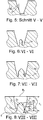
Fig. 5 einen Schnitt entlang der Linie V-V derFig. 2 , -
Fig. 6 einen Schnitt entlang der Linie VI-VI derFig. 2 , -
Fig. 7 einen Schnitt entlang der Linie VII-VII derFig. 2 , -
Fig. 8 einen Schnitt entlang der Linie VIII-VIII derFig. 2 , -
Fig. 9a eine Draufsicht auf einen Umfangsabschnitt einer Umfangsrille eines Laufstreifens mit einer zweiten Ausführungsvariante der Erfindung, -
Fig. 9b eine Schrägansicht auf den Umfangsabschnitt ausFig. 9a , -
Fig. 10a eine Draufsicht auf einen Umfangsabschnitt einer Umfangsrille eines Laufstreifens mit einer dritten Ausführungsvariante der Erfindung, -
Fig. 10b eine Schrägansicht auf den Umfangsabschnitt ausFig. 10a und -
Fig. 10c einen Schnitt entlang der Linie Xc-Xc derFig. 10a . - Erfindungsgemäß ausgeführte Nutzfahrzeugreifen sind Reifen in Radialbauart, insbesondere für Baustellenfahrzeuge, Lastkraftwagen oder Busse.
- Der in
Fig. 1 gezeigte zentrale Umfangsabschnitt eines Laufstreifens weist vier in Umfangsrichtung umlaufende Profilpositive 1 auf, welche schematisch und vereinfacht dargestellt sind und insbesondere in bekannter Weise ausgeführte Profilbänder oder Profilblockreihen sind. In axialer Richtung benachbarte Profilpositive 1 sind von je einer in Draufsicht gerade verlaufenden Umfangsrille 2 getrennt. - Die Umfangsrillen 2 sind beim gezeigten Ausführungsbeispiel übereinstimmend ausgeführt. Die Ausgestaltung der Umfangsrillen 2 wird nachfolgend anhand der in
Fig. 2 bis Fig. 8 gezeigten Umfangsrille 2 beschrieben. - Wie
Fig. 2 und Fig. 3 zeigen, ist die Umfangsrille 2 an der Laufstreifenperipherie durch zwei im Wesentlichen in Umfangsrichtung und im gezeigten Ausführungsbeispiel in Draufsicht leicht wellenförmig verlaufende Rillenkanten 3 sowie ferner durch an die Rillenkanten 3 anschließende Rillenwände 4 und einen Rillengrund 5 begrenzt. Die Umfangsrille 2 weist in radialer Richtung an ihrer tiefsten Stelle die für den jeweiligen Nutzfahrzeugreifen vorgesehene Profiltiefe T1 (Fig. 4 ,Fig. 8 ) von 12,0 mm bis 26,0 mm und an der Laufstreifenperipherie an ihrer breitesten Stelle in axialer Richtung eine Breite B1 (Fig. 8 ) von insbesondere 10,0 mm bis 25,0 mm auf. GemäßFig. 4 bis Fig. 8 weisen die Rillenwände 4 beim gezeigten Ausführungsbeispiel, im Querschnitt betrachtet, in radialer Richtung verlaufende radial äußere Abschnitte auf, zwischen welche die Umfangsrille 2 ebenfalls die Breite B1 aufweist. - Jede Rillenwand 4 begrenzt und bildet eine Vielzahl von in Umfangsrichtung aufeinanderfolgenden, in regelmäßigen Abständen über die gesamte Erstreckung der Umfangsrille 2 angeordneten, flach nasenartigen Vorsprüngen 6, wobei jeder Vorsprung 6 von einem Wandabschnitt 4a der jeweiligen Rillenwand 4 begrenzt ist. Die von Wandabschnitten 4a an beiden Rillenwänden 4 begrenzten Vorsprünge 6 liegen einander paarweise gegenüber und sind bezüglich einer von der Umfangsrichtung und der radialen Richtung aufgespannten, durch die Mitte der Umfangsrille 2 verlaufenden Ebene symmetrisch ausgeführt.
- Jeder Vorsprung 6 ist zusätzlich bezüglich einer von der radialen Richtung und der axialen Richtung aufgespannten, durch die Mitte des Vorsprunges 6 verlaufenden Ebene, welche entlang der in
Fig. 2 eingezeichneten Schnittlinie IV-IV verläuft, symmetrisch ausgeführt. Die die Vorsprünge 6 begrenzenden Wandabschnitte 4a setzen sich aus einem den Nasenrücken bildenden, leicht nach außen gekrümmten mittleren Wandbereich 4aI und zwei an diesen anschließenden, die Nasenflügel bildenden, seitlichen Wandbereichen 4aII zusammen. Der mittlere Wandbereich 4aI des Wandabschnittes 4a verläuft in der erwähnten, mit der Schnittlinie IV-IV zusammenfallenden Ebene, im Querschnitt betrachtet, zur radialen Richtung unter einem Winkel α (Fig. 4 ) von 10° bis 30°. Die seitlichen Wandbereiche 4aII des Wandabschnittes 4a sind vorzugsweise ebene Flächen, welche zur Umfangsrichtung geneigt sind (Fig. 3 ) und, im Querschnitt betrachtet, zur radialen Richtung unter einem Winkel β (Fig. 5 ) von beispielsweise 5° bis 25° verlaufen, wobei β < α gilt. - Zwischen den an derselben Rillenwand 4 ausgebildeten, in Umfangsrichtung unmittelbar aufeinanderfolgenden Vorsprüngen 6 verlaufen in Draufsicht sichelförmige Wandabschnitte 4b. Die zu einer Rillenwand 4 gehörenden sichelförmigen Wandabschnitte 4b sind bezüglich der jeweils zur gegenüberliegenden Rillenwand 4 gehörenden sichelförmigen Wandabschnitte 4b in Draufsicht konvex gekrümmt. Entsprechend ihrer Sichelform laufen die Wandabschnitte 4b entlang der die Nasenflügel bildenden, seitlichen Wandbereiche 4aII aus. Ferner sind die Wandabschnitte 4b, im Querschnitt betrachtet, derart leicht gebogen, sodass die zu den unterschiedlichen Rillenwänden 4 gehörenden Wandabschnitte 4b auch im Querschnitt leicht konvex zueinander gekrümmt sind (
Fig. 7, Fig. 8 ). - In jedem Zwischenraum, welcher sich zwischen gegenüberliegenden, zueinander konvex gekrümmten Wandabschnitten 4b befindet, ist mittig am Rillengrund 5 der Umfangsrille 2 eine als Steinauswerfer wirkende Grundanhebung 7 ausgebildet. Jede Grundanhebung 7 befindet sich daher zwischen zwei in Umfangsrichtung unmittelbar aufeinanderfolgenden Paaren von gegenüberliegenden Vorsprüngen 6. In Draufsicht weist jede Grundanhebung 7 die Form einer in Umfangsrichtung langgestreckten Raute mit abgerundeten Ecken, insbesondere im Wesentlichen die Gestalt eines "Footballs", auf. Am Rillengrund 5 der Umfangsrille 2 verbleibt ein Rillenpfad 2a (
Fig. 3 ), welcher sämtliche Grundanhebungen 7 umläuft und sich in Draufsicht im Wesentlichen entlang von zwei sich kreuzenden Wellen erstreckt, die eine übereinstimmende Wellenlänge aufweisen und um die Hälfte der Wellenlänge in Umfangsrichtung zueinander phasenverschoben sind. - Der Rillenpfad 2a weist zwischen den mittleren Wandbereichen 4aI einander gegenüberliegender Vorsprünge 6 in radialer Richtung eine Tiefe T2 (
Fig. 4 ) von bis zu 4,0 mm, insbesondere von zu 3,0 mm, auf. Ferner weist der Rillenpfad 2a zwischen diesen Wandbereichen 4aI an seiner schmalsten Stelle in axialer Richtung eine Breite B2 (Fig. 4 ) von 15% bis 45%, insbesondere von höchstens 35%, der Breite B1 (Fig. 8 ) der Umfangsrille 2 auf. Im Bereich zwischen den sichelförmigen Wandabschnitten 4b und den Grundanhebungen 7 ist die Breite des Rillenpfades 2a derart, dass die Grundanhebungen 7 an der schmalsten Stelle des Rillenpfades 2a zu den sichelförmigen Wandabschnitten 4b in axialer Richtung einen Abstand a1 (Fig. 8 ) von 2,0 mm bis 4,0 mm aufweisen. - Jede Grundanhebung 7 weist in Umfangsrichtung eine größte Erstreckungslänge l1 (
Fig. 2 ) von 10,0 mm bis 35,0 mm, insbesondere von 15,0 mm bis 25,0 mm, auf, welche mit den Abständen in Umfangsrichtung aufeinanderfolgender paarweiser einander zugeordneter Vorsprünge 6 korreliert. In radialer Richtung weist jede Grundanhebung 7 in ihrem mittleren Bereich an ihrer höchsten Stelle eine Höhe h1 (Fig. 8 ) auf, welche 25% bis 60%, insbesondere 30% bis 55%, und besonders bevorzugter Weise höchstens 50%, der jeweils vorgesehenen Profiltiefe T1 beträgt. In axialer Richtung weist jede Grundanhebung 7 an ihrer breitesten Stelle eine Breite b1 (Fig. 2 ) von 5,0 mm bis 15,0 mm auf. - Gemäß
Fig. 3 setzt sich jede Grundanhebung 7 aus einem Basisteil 7a und einem auf diesen aufgesetzten kuppelartigen Oberteil 7b zusammen. WieFig. 6 bis Fig. 8 zeigen, ist der Basisteil 7a im Querschnitt rechteckig ausgeführt und weist in radialer Richtung eine ausgehend vom Rillengrund 5 ermittelte Höhe h2 auf, welche 35% bis 80%, insbesondere 40% bis 60%, der Höhe h1 der Grundanhebung 7 entspricht (Fig. 8 ). - Der kuppelartige Oberteil 7b ist in radialer Richtung durch eine Deckfläche 8 (
Fig. 8 ) begrenzt, welche von der an der höchsten Stelle der Grundanhebung 7 vorliegenden Höhe h1 zu den Rändern des kuppelartigen Oberteiles 7b gleichmäßig auf die Höhe h2 abfällt. Wie insbesondereFig. 2 und Fig. 3 zeigen, ist die Deckfläche 8 vorzugsweise von mehreren, beim gezeigten Ausführungsbeispiel von neun, ebenen Teildeckflächen gebildet. -
Fig. 9a und Fig. 9b zeigen eine Umfangsrille 2', welche eine Variante der Umfangsrille 2 ist und sich von dieser durch in Draufsicht wellenförmig verlaufende Rillenkanten 3' sowie durch an diese anschließende, in Draufsicht wellenförmig verlaufende Rillenwände 4' unterscheidet. Die Rillenwände 4' verlaufen zur radialen Richtung vorzugszugsweise unter einem konstanten Winkel von 5° bis 30°, insbesondere von 10° bis 20°. Die beiden Rillenkanten 3' und die beiden Rillenwände 4' sind zueinander jeweils bezüglich einer von der Umfangsrichtung und der radialen Richtung aufgespannten Ebene symmetrisch ausgeführt, wobei die Umfangsrille 2' an der Laufstreifenperipherie an ihrer breitesten Stelle eine Breite B1' und an der schmalsten Stelle eine Breite B2' aufweist. Die Breite B1' beträgt 10,0 mm bis 25,0 mm, die Breite B2' beträgt 75% bis 95% der Breite B1'. Die Rillenwände 4' weisen in Umfangsrichtung abwechselnd in Draufsicht zueinander konkav gekrümmte Wandabschnitte 4'a und in Draufsicht zueinander konvex gekrümmte Wandabschnitte 4'b auf - In jedem Zwischenraum, welcher sich zwischen gegenüberliegenden, zueinander konvex gekrümmten Wandabschnitten 4'b befindet, ist mittig am Rillengrund der Umfangsrille 2' eine zur Grundanhebung 7 der ersten Ausführungsvariante (
Fig. 1 bis Fig. 8 ) übereinstimmend gestaltete Grundanhebung 7' mit einer Deckfläche 8' ausgebildet, welche beim gezeigten Ausführungsbeispiel die Rillenwände 4' an ihren radial inneren Endbereichen kontaktiert (Fig. 9b ). Bevorzugter Weise verbleibt am Rillengrund der Umfangsrille 2' ein Rillenpfad, welcher sämtliche Grundanhebungen 7' umläuft und in axialer Richtung zu den Wandabschnitten 4'b einen Abstand von 2,0 mm bis 4,0 mm aufweist. Vom Rillengrund der Umfangsrille 2' verbleibt eine Vielzahl von zwischen einander benachbarten Grundanhebungen 7' auf Profiltiefe verlaufenden, in Draufsicht in Umfangsrichtung langgestreckt X-artigen Rillengrundbereichen 5'. -
Fig. 10a und Fig. 10b zeigen eine Umfangsrille 2", welche eine weitere Variante der Umfangsrille 2 ist. Die Umfangsrille 2" unterscheidet sich von der Umfangsrille 2 durch von deren Grundanhebungen 7 abweichend gestalteten Grundanhebungen 7". Die Grundanhebungen 7" sind in radialer Richtung durch eine Deckfläche 8" begrenzt, welche eine parallel zur Laufstreifenperipherie ausgerichtete Kerndeckfläche 8"a und eine diese umlaufende zum Rand der Grundanhebung 7" abfallende Randdeckfläche 8"b aufweist. In radialer Richtung weisen die Grundanhebungen 7" im Bereich der Kerndeckfläche 8"a eine Höhe h3 (Fig. 10c ) auf, welche 25% bis 60%, insbesondere 30% bis 55%, und besonders bevorzugter Weise höchstens 50%, der Profiltiefe T1 beträgt. WieFig. 10c . zeigt, setzen sich die Grundanhebungen 7" aus einem Basisteil 7"a und einem auf diesem aufgesetzten, im Querschnitt trapezförmigen Oberteil 7"b zusammen. Der Basisteil 7"a reicht in radialer Richtung bis in eine Höhe h4, welche 35% bis 90%, insbesondere 70% bis 80%, der Höhe h3 der Grundanhebung 7" entspricht (Fig. 8 ). - Die Erfindung ist auf die beschriebenen Ausführungsvarianten nicht beschränkt. Die Grundanhebungen können eine von der beschriebenen Gestalt abweichende Form aufweisen, insbesondere die Form von halben Ellipsoiden oder in Form von Teilstücken von halben Ellipsoiden. Die Rillenwände der Umfangsrillen können auch ohne den im Zusammenhang mit der ersten Ausführungsvariante (
Fig. 4 bis Fig. 8 ) erwähnten, in radialer Richtung verlaufenden radial äußeren Abschnitten ausgeführt sein. -
- 1
- Profilpositiv
- 2, 2', 2"
- Umfangsrille
- 2a
- Rillenpfad
- 3, 3'
- Rillenkante
- 4,
- Rillenwand
- 4a, 4'a
- Wandabschnitt
- 4aI, 4aII
- Wandbereich
- 4b, 4'b
- Wandabschnitt
- 4c
- Verbindungsfläche
- 5
- Rillengrund
- 5'
- Rillengrundbereich
- 6
- Vorsprung
- 7, 7', 7"
- Grundanhebung
- 7a, 7"a
- Basisteil
- 7b, 7"b
- Oberteil
- 8, 8', 8"
- Deckfläche
- 8"a
- Kerndeckfläche
- 8"b
- Randdeckfläche
- a1
- Abstand
- b1
- Breite
- B1, B2
- Breite
- B1', B2'
- Breite
- l1
- Erstreckungslänge
- h1, h2, h3, h4
- Höhe
- T1
- Profiltiefe
- T2
- Tiefe
- α, β
- Winkel
Claims (14)
- Nutzfahrzeugreifen mit einem Laufstreifen mit zumindest einer Umfangsrille (2, 2', 2") mit einem Rillengrund (5) und Rillenwänden (4, 4'), wobei am Rillengrund (5) über den Umfang verteilt und mittig als Steinauswerfer wirkende Grundanhebungen (7, 7', 7") mit einer Höhe (h1, h3) und einer größeren Erstreckung in Umfangsrichtung als in axialer Richtung ausgebildet sind, wobei die Grundanhebungen (7, 7', 7") entweder die Rillenwände (4, 4') kontaktieren oder von diesen in axialer Richtung Abstände (a1) von bis zu 4,0 mm aufweisen und in radialer Richtung von einer Deckfläche (8, 8', 8") mit einem umlaufenden Flächenrand begrenzt sind, wobei die Deckfläche (8, 8', 8") zum Flächenrand abfällt, wobei die Rillenwände (4, 4') zwischen den Grundanhebungen (7, 7', 7") sich zueinander annähernde Wandabschnitte (4a, 4'a) und seitlich der Grundanhebungen (7, 7', 7") in Draufsicht zueinander konvex gekrümmte Wandabschnitte (4b, 4'b) aufweisen und wobei der Flächenrand der Deckfläche (8, 8', 8") dem Verlauf der zueinander konvex gekrümmten Wandabschnitte (4b, 4'b) derart folgt, dass die Breite der Grundanhebungen (7, 7', 7") zu ihren in Umfangsrichtung liegenden Enden abnimmt,dadurch gekennzeichnet,dass die Deckfläche von der an der höchsten Stelle der jeweiligen Grundanhebung (7, 7', 7") vorliegenden Höhe (h1) gleichmäßig auf die Höhe (h2) des Flächenrands abfällt, wobei die maximale Höhe (h1, h3) der Grundanhebungen (7, 7', 7") in radialer Richtung 25% bis 60% der Profiltiefe (T1) beträgt unddass die in Draufsicht zueinander konvex gekrümmten Wandabschnitte (4b, 4'b) der Rillenwände (4, 4'), im Querschnitt der Umfangsrille (2, 2', 2") betrachtet, zumindest über den Großteil ihrer radialen Erstreckung konvex zueinander gekrümmt sind.
- Nutzfahrzeugreifen nach Anspruch 1, dadurch gekennzeichnet, dass die Grundanhebungen (7, 7', 7") in Draufsicht die Gestalt von in Umfangsrichtung langgestreckten Rauten mit abgerundeten Ecken aufweisen.
- Nutzfahrzeugreifen nach Anspruch 1 oder 2, dadurch gekennzeichnet, dass sich die Grundanhebungen (7, 7', 7") aus einem Basisteil (7a, 7"a) mit einer in radialer Richtung konstanten Höhe (h2) und einem auf diesen aufgesetzten kuppelartigen Oberteil (7b, 7"b) zusammensetzen.
- Nutzfahrzeugreifen nach Anspruch 3, dadurch gekennzeichnet, dass die Höhe (h2, h4) des Basisteiles (7a, 7"a) der Grundanhebungen (7, 7', 7") 35% bis 90%, insbesondere 40% bis 80%, der maximalen Höhe (h1, h3) der Grundanhebungen (7, 7', 7") beträgt.
- Nutzfahrzeugreifen nach einem der Ansprüche 1 bis 4, dadurch gekennzeichnet, dass die Deckfläche (8") der Grundanhebungen (7") eine Kerndeckfläche (8"a) und eine diese umlaufende zum Flächenrand der Deckfläche (8") abfallende Randdeckfläche (8"b) aufweist.
- Nutzfahrzeugreifen nach Anspruch 1 oder 2, dadurch gekennzeichnet, dass die Grundanhebungen ausschließlich von ihren Deckflächen begrenzt sind.
- Nutzfahrzeugreifen nach Anspruch 1, 2 oder 6, dadurch gekennzeichnet, dass die Grundanhebungen die Gestalt eines halben Ellipsoids oder eines Teilstückes eines halben Ellipsoids aufweisen.
- Nutzfahrzeugreifen nach einem der Ansprüche 1 bis 7, dadurch gekennzeichnet, dass die Grundanhebungen (7, 7', 7") in Umfangsrichtung an ihrer längsten Stelle eine Erstreckungslänge (l1) von 10,0 mm bis 35,0 mm, insbesondere von 15,0 mm bis 25,0 mm, aufweisen.
- Nutzfahrzeugreifen nach einem der Ansprüche 1 bis 8, dadurch gekennzeichnet, dass die maximale Höhe (h1, h3) der Grundanhebungen (7, 7', 7") 30% bis 55%, vorzugsweise höchstens 50%, der Profiltiefe (T1) beträgt.
- Nutzfahrzeugreifen nach einem der Ansprüche 1 bis 9, dadurch gekennzeichnet, dass die Grundanhebungen (7, 7', 7") in axialer Richtung an ihrer breitesten Stelle eine Breite (b1) von 5,0 mm bis 15,0 mm aufweisen.
- Nutzfahrzeugreifen nach einem der Ansprüche 1 bis 10, dadurch gekennzeichnet, dass zwischen den Wandabschnitten (4a), welche sich zwischen den Grundanhebungen (7, 7") zueinander annähern, ein Rillenpfad (2a) der Umfangsrille (2, 2") verläuft, welcher an seiner schmalsten Stelle eine Breite (B2) von 15% bis 45%, insbesondere von höchstens 35%, der Breite (B1) der Umfangsrille (2, 2") an der Laufstreifenperipherie aufweist.
- Nutzfahrzeugreifen nach einem der Ansprüche 1 bis 11, dadurch gekennzeichnet, dass die Wandabschnitte (4a, 4'a), welche sich zwischen den Grundanhebungen (7, 7") zueinander annähern, in die Umfangsrille (2, 2") hineinragende, paarweise gegenüberliegende, insbesondere nasenartig gestaltete Vorsprünge (6) begrenzen.
- Nutzfahrzeugreifen nach einem der Ansprüche 1 bis 12, dadurch gekennzeichnet, dass die in Draufsicht zueinander konvex gekrümmten Wandabschnitte (4b) zu den Grundanhebungen (7, 7") an ihren radial inneren Enden einen Abstand (a1) von 2,0 mm bis 4,0 mm aufweisen.
- Nutzfahrzeugreifen nach einem der Ansprüche 1 bis 11, dadurch gekennzeichnet, dass die Rillenwände (4') der Umfangsrille (2') in Draufsicht wellenförmig und bezüglich einer von der Umfangsrichtung und der radialen Richtung aufgespannten Ebene symmetrisch verlaufen.
Applications Claiming Priority (2)
| Application Number | Priority Date | Filing Date | Title |
|---|---|---|---|
| DE102017219532.0A DE102017219532A1 (de) | 2017-11-03 | 2017-11-03 | Nutzfahrzeugreifen |
| PCT/EP2018/070527 WO2019086153A1 (de) | 2017-11-03 | 2018-07-30 | Nutzfahrzeugreifen |
Publications (2)
| Publication Number | Publication Date |
|---|---|
| EP3703960A1 EP3703960A1 (de) | 2020-09-09 |
| EP3703960B1 true EP3703960B1 (de) | 2021-09-22 |
Family
ID=63077862
Family Applications (1)
| Application Number | Title | Priority Date | Filing Date |
|---|---|---|---|
| EP18748894.5A Active EP3703960B1 (de) | 2017-11-03 | 2018-07-30 | Nutzfahrzeugreifen |
Country Status (6)
| Country | Link |
|---|---|
| US (1) | US11945262B2 (de) |
| EP (1) | EP3703960B1 (de) |
| CN (1) | CN111278667B (de) |
| DE (1) | DE102017219532A1 (de) |
| ES (1) | ES2898236T3 (de) |
| WO (1) | WO2019086153A1 (de) |
Families Citing this family (14)
| Publication number | Priority date | Publication date | Assignee | Title |
|---|---|---|---|---|
| JP7310314B2 (ja) * | 2019-05-31 | 2023-07-19 | 住友ゴム工業株式会社 | タイヤ |
| US20220258542A1 (en) * | 2019-07-17 | 2022-08-18 | Bridgestone Bandag, Llc | Pre-cured tread stone rejection design |
| DE102020200265A1 (de) | 2020-01-10 | 2021-07-15 | Continental Reifen Deutschland Gmbh | Fahrzeugluftreifen |
| WO2021178819A1 (en) | 2020-03-06 | 2021-09-10 | Berkshire Grey, Inc. | Systems and methods for providing order fulfillment using a shuttle takeaway system |
| EP4114769A1 (de) | 2020-03-06 | 2023-01-11 | Berkshire Grey Operating Company, Inc. | Systeme und verfahren zur auftragserfüllung unter verwendung eines spiralturmsystems |
| CN113370719B (zh) * | 2021-06-29 | 2023-05-12 | 赛轮集团股份有限公司 | 轮胎 |
| CN113415109A (zh) * | 2021-07-08 | 2021-09-21 | 双钱集团上海轮胎研究所有限公司 | 一种轮胎 |
| CN115703308A (zh) * | 2021-08-05 | 2023-02-17 | 正新橡胶工业股份有限公司 | 防夹石的轮胎花纹结构 |
| TWI780852B (zh) * | 2021-08-05 | 2022-10-11 | 正新橡膠工業股份有限公司 | 防夾石之輪胎花紋結構 |
| DE102021210020A1 (de) * | 2021-09-10 | 2023-03-16 | Continental Reifen Deutschland Gmbh | Fahrzeugluftreifen |
| JP2023124168A (ja) | 2022-02-25 | 2023-09-06 | 住友ゴム工業株式会社 | タイヤ |
| JP7850591B2 (ja) | 2022-04-19 | 2026-04-23 | 株式会社ブリヂストン | タイヤ |
| DE102022211763A1 (de) | 2022-11-08 | 2024-05-08 | Continental Reifen Deutschland Gmbh | Fahrzeugreifen |
| KR102787251B1 (ko) * | 2023-03-28 | 2025-03-31 | 한국타이어앤테크놀로지 주식회사 | 돌물림 방지 타이어 |
Family Cites Families (16)
| Publication number | Priority date | Publication date | Assignee | Title |
|---|---|---|---|---|
| JPS595443B2 (ja) | 1979-11-29 | 1984-02-04 | 株式会社ブリヂストン | 重荷重用空気入りタイヤ |
| JPH064365B2 (ja) | 1986-07-17 | 1994-01-19 | 住友ゴム工業株式会社 | 重車両用空気入りタイヤ |
| DE3727050A1 (de) | 1987-08-13 | 1989-02-23 | Sumitomo Rubber Ind | Luftreifen fuer schwerlastfahrzeuge |
| USD394034S (en) * | 1997-04-29 | 1998-05-05 | The Goodyear Tire & Rubber Company | Tire tread |
| JP2004155382A (ja) * | 2002-11-08 | 2004-06-03 | Bridgestone Corp | 空気入りタイヤ |
| JP5044291B2 (ja) * | 2007-06-04 | 2012-10-10 | 東洋ゴム工業株式会社 | 空気入りタイヤ |
| CN102202917B (zh) * | 2008-10-31 | 2014-06-04 | 倍耐力轮胎股份公司 | 车轮用轮胎 |
| WO2010090327A1 (ja) * | 2009-02-09 | 2010-08-12 | 株式会社ブリヂストン | 空気入りタイヤ |
| DE102009044123A1 (de) * | 2009-09-29 | 2011-03-31 | Continental Reifen Deutschland Gmbh | Laufstreifenprofil eines Fahrzeugluftreifens |
| JP5743328B2 (ja) * | 2010-01-28 | 2015-07-01 | 株式会社ブリヂストン | タイヤ |
| JP5580073B2 (ja) * | 2010-02-19 | 2014-08-27 | 株式会社ブリヂストン | タイヤ |
| JP5491953B2 (ja) * | 2010-05-07 | 2014-05-14 | 株式会社ブリヂストン | タイヤ |
| JP5723636B2 (ja) * | 2011-03-07 | 2015-05-27 | 株式会社ブリヂストン | タイヤ |
| DE102012104403A1 (de) * | 2012-05-22 | 2013-11-28 | Continental Reifen Deutschland Gmbh | Laufstreifenprofil eines Fahrzeugluftreifens |
| NO2795041T3 (de) * | 2015-06-01 | 2018-01-27 | ||
| DE102015215455A1 (de) | 2015-08-13 | 2017-02-16 | Continental Reifen Deutschland Gmbh | Fahrzeugluftreifen |
-
2017
- 2017-11-03 DE DE102017219532.0A patent/DE102017219532A1/de not_active Withdrawn
-
2018
- 2018-07-30 US US16/758,946 patent/US11945262B2/en active Active
- 2018-07-30 WO PCT/EP2018/070527 patent/WO2019086153A1/de not_active Ceased
- 2018-07-30 CN CN201880069868.3A patent/CN111278667B/zh active Active
- 2018-07-30 ES ES18748894T patent/ES2898236T3/es active Active
- 2018-07-30 EP EP18748894.5A patent/EP3703960B1/de active Active
Also Published As
| Publication number | Publication date |
|---|---|
| EP3703960A1 (de) | 2020-09-09 |
| US20210178826A1 (en) | 2021-06-17 |
| ES2898236T3 (es) | 2022-03-04 |
| US11945262B2 (en) | 2024-04-02 |
| DE102017219532A1 (de) | 2019-05-09 |
| CN111278667B (zh) | 2022-06-24 |
| CN111278667A (zh) | 2020-06-12 |
| WO2019086153A1 (de) | 2019-05-09 |
Similar Documents
| Publication | Publication Date | Title |
|---|---|---|
| EP3703960B1 (de) | Nutzfahrzeugreifen | |
| EP2646263B1 (de) | Fahrzeugluftreifen | |
| EP3390110B1 (de) | Fahrzeugluftreifen | |
| DE102007061148A1 (de) | Fahrzeugluftreifen | |
| EP2463123B1 (de) | Fahrzeugluftreifen | |
| DE102010060945A1 (de) | Fahrzeugluftreifen | |
| EP3421264B1 (de) | Fahrzeugluftreifen | |
| EP2666648B1 (de) | Fahrzeugluftreifen | |
| EP3256335B1 (de) | Fahrzeugluftreifen | |
| EP3597449A1 (de) | Fahrzeugluftreifen | |
| EP3390108B1 (de) | Fahrzeugluftreifen | |
| DE102008029659A1 (de) | Fahrzeugluftreifen | |
| EP2990235A1 (de) | Fahrzeugluftreifen | |
| EP2138329B1 (de) | Laufflächenprofil für einen Fahrzeugluftreifen | |
| EP3560735B1 (de) | Nutzfahrzeugreifen | |
| EP3418077B1 (de) | Fahrzeugluftreifen | |
| EP3663105B1 (de) | Fahrzeugreifen | |
| EP2138328A1 (de) | Fahrzeugluftreifen | |
| EP3418076B1 (de) | Fahrzeugluftreifen | |
| EP3917791B1 (de) | Fahrzeugluftreifen | |
| DE102006058086B4 (de) | Fahrzeugluftreifen | |
| EP3999361B1 (de) | Nutzfahrzeugreifen | |
| EP3753753B1 (de) | Fahrzeugluftreifen | |
| EP3785937B1 (de) | Fahrzeugluftreifen | |
| EP3750722B1 (de) | Fahrzeugluftreifen |
Legal Events
| Date | Code | Title | Description |
|---|---|---|---|
| STAA | Information on the status of an ep patent application or granted ep patent |
Free format text: STATUS: UNKNOWN |
|
| STAA | Information on the status of an ep patent application or granted ep patent |
Free format text: STATUS: THE INTERNATIONAL PUBLICATION HAS BEEN MADE |
|
| PUAI | Public reference made under article 153(3) epc to a published international application that has entered the european phase |
Free format text: ORIGINAL CODE: 0009012 |
|
| STAA | Information on the status of an ep patent application or granted ep patent |
Free format text: STATUS: REQUEST FOR EXAMINATION WAS MADE |
|
| 17P | Request for examination filed |
Effective date: 20200603 |
|
| AK | Designated contracting states |
Kind code of ref document: A1 Designated state(s): AL AT BE BG CH CY CZ DE DK EE ES FI FR GB GR HR HU IE IS IT LI LT LU LV MC MK MT NL NO PL PT RO RS SE SI SK SM TR |
|
| AX | Request for extension of the european patent |
Extension state: BA ME |
|
| RAP1 | Party data changed (applicant data changed or rights of an application transferred) |
Owner name: CONTINENTAL REIFEN DEUTSCHLAND GMBH |
|
| DAV | Request for validation of the european patent (deleted) | ||
| DAX | Request for extension of the european patent (deleted) | ||
| GRAP | Despatch of communication of intention to grant a patent |
Free format text: ORIGINAL CODE: EPIDOSNIGR1 |
|
| STAA | Information on the status of an ep patent application or granted ep patent |
Free format text: STATUS: GRANT OF PATENT IS INTENDED |
|
| INTG | Intention to grant announced |
Effective date: 20210602 |
|
| GRAS | Grant fee paid |
Free format text: ORIGINAL CODE: EPIDOSNIGR3 |
|
| GRAA | (expected) grant |
Free format text: ORIGINAL CODE: 0009210 |
|
| STAA | Information on the status of an ep patent application or granted ep patent |
Free format text: STATUS: THE PATENT HAS BEEN GRANTED |
|
| AK | Designated contracting states |
Kind code of ref document: B1 Designated state(s): AL AT BE BG CH CY CZ DE DK EE ES FI FR GB GR HR HU IE IS IT LI LT LU LV MC MK MT NL NO PL PT RO RS SE SI SK SM TR |
|
| REG | Reference to a national code |
Ref country code: GB Ref legal event code: FG4D Free format text: NOT ENGLISH |
|
| REG | Reference to a national code |
Ref country code: IE Ref legal event code: FG4D Free format text: LANGUAGE OF EP DOCUMENT: GERMAN |
|
| REG | Reference to a national code |
Ref country code: DE Ref legal event code: R096 Ref document number: 502018007186 Country of ref document: DE |
|
| REG | Reference to a national code |
Ref country code: CH Ref legal event code: EP Ref country code: AT Ref legal event code: REF Ref document number: 1432038 Country of ref document: AT Kind code of ref document: T Effective date: 20211015 |
|
| REG | Reference to a national code |
Ref country code: LT Ref legal event code: MG9D |
|
| REG | Reference to a national code |
Ref country code: NL Ref legal event code: MP Effective date: 20210922 |
|
| PG25 | Lapsed in a contracting state [announced via postgrant information from national office to epo] |
Ref country code: NO Free format text: LAPSE BECAUSE OF FAILURE TO SUBMIT A TRANSLATION OF THE DESCRIPTION OR TO PAY THE FEE WITHIN THE PRESCRIBED TIME-LIMIT Effective date: 20211222 Ref country code: BG Free format text: LAPSE BECAUSE OF FAILURE TO SUBMIT A TRANSLATION OF THE DESCRIPTION OR TO PAY THE FEE WITHIN THE PRESCRIBED TIME-LIMIT Effective date: 20211222 Ref country code: LT Free format text: LAPSE BECAUSE OF FAILURE TO SUBMIT A TRANSLATION OF THE DESCRIPTION OR TO PAY THE FEE WITHIN THE PRESCRIBED TIME-LIMIT Effective date: 20210922 Ref country code: SE Free format text: LAPSE BECAUSE OF FAILURE TO SUBMIT A TRANSLATION OF THE DESCRIPTION OR TO PAY THE FEE WITHIN THE PRESCRIBED TIME-LIMIT Effective date: 20210922 Ref country code: RS Free format text: LAPSE BECAUSE OF FAILURE TO SUBMIT A TRANSLATION OF THE DESCRIPTION OR TO PAY THE FEE WITHIN THE PRESCRIBED TIME-LIMIT Effective date: 20210922 Ref country code: HR Free format text: LAPSE BECAUSE OF FAILURE TO SUBMIT A TRANSLATION OF THE DESCRIPTION OR TO PAY THE FEE WITHIN THE PRESCRIBED TIME-LIMIT Effective date: 20210922 Ref country code: FI Free format text: LAPSE BECAUSE OF FAILURE TO SUBMIT A TRANSLATION OF THE DESCRIPTION OR TO PAY THE FEE WITHIN THE PRESCRIBED TIME-LIMIT Effective date: 20210922 |
|
| PG25 | Lapsed in a contracting state [announced via postgrant information from national office to epo] |
Ref country code: LV Free format text: LAPSE BECAUSE OF FAILURE TO SUBMIT A TRANSLATION OF THE DESCRIPTION OR TO PAY THE FEE WITHIN THE PRESCRIBED TIME-LIMIT Effective date: 20210922 Ref country code: GR Free format text: LAPSE BECAUSE OF FAILURE TO SUBMIT A TRANSLATION OF THE DESCRIPTION OR TO PAY THE FEE WITHIN THE PRESCRIBED TIME-LIMIT Effective date: 20211223 |
|
| REG | Reference to a national code |
Ref country code: ES Ref legal event code: FG2A Ref document number: 2898236 Country of ref document: ES Kind code of ref document: T3 Effective date: 20220304 |
|
| PG25 | Lapsed in a contracting state [announced via postgrant information from national office to epo] |
Ref country code: IS Free format text: LAPSE BECAUSE OF FAILURE TO SUBMIT A TRANSLATION OF THE DESCRIPTION OR TO PAY THE FEE WITHIN THE PRESCRIBED TIME-LIMIT Effective date: 20220122 Ref country code: SK Free format text: LAPSE BECAUSE OF FAILURE TO SUBMIT A TRANSLATION OF THE DESCRIPTION OR TO PAY THE FEE WITHIN THE PRESCRIBED TIME-LIMIT Effective date: 20210922 Ref country code: RO Free format text: LAPSE BECAUSE OF FAILURE TO SUBMIT A TRANSLATION OF THE DESCRIPTION OR TO PAY THE FEE WITHIN THE PRESCRIBED TIME-LIMIT Effective date: 20210922 Ref country code: PT Free format text: LAPSE BECAUSE OF FAILURE TO SUBMIT A TRANSLATION OF THE DESCRIPTION OR TO PAY THE FEE WITHIN THE PRESCRIBED TIME-LIMIT Effective date: 20220124 Ref country code: PL Free format text: LAPSE BECAUSE OF FAILURE TO SUBMIT A TRANSLATION OF THE DESCRIPTION OR TO PAY THE FEE WITHIN THE PRESCRIBED TIME-LIMIT Effective date: 20210922 Ref country code: NL Free format text: LAPSE BECAUSE OF FAILURE TO SUBMIT A TRANSLATION OF THE DESCRIPTION OR TO PAY THE FEE WITHIN THE PRESCRIBED TIME-LIMIT Effective date: 20210922 Ref country code: EE Free format text: LAPSE BECAUSE OF FAILURE TO SUBMIT A TRANSLATION OF THE DESCRIPTION OR TO PAY THE FEE WITHIN THE PRESCRIBED TIME-LIMIT Effective date: 20210922 Ref country code: CZ Free format text: LAPSE BECAUSE OF FAILURE TO SUBMIT A TRANSLATION OF THE DESCRIPTION OR TO PAY THE FEE WITHIN THE PRESCRIBED TIME-LIMIT Effective date: 20210922 Ref country code: AL Free format text: LAPSE BECAUSE OF FAILURE TO SUBMIT A TRANSLATION OF THE DESCRIPTION OR TO PAY THE FEE WITHIN THE PRESCRIBED TIME-LIMIT Effective date: 20210922 |
|
| REG | Reference to a national code |
Ref country code: DE Ref legal event code: R097 Ref document number: 502018007186 Country of ref document: DE |
|
| PG25 | Lapsed in a contracting state [announced via postgrant information from national office to epo] |
Ref country code: DK Free format text: LAPSE BECAUSE OF FAILURE TO SUBMIT A TRANSLATION OF THE DESCRIPTION OR TO PAY THE FEE WITHIN THE PRESCRIBED TIME-LIMIT Effective date: 20210922 |
|
| PLBE | No opposition filed within time limit |
Free format text: ORIGINAL CODE: 0009261 |
|
| STAA | Information on the status of an ep patent application or granted ep patent |
Free format text: STATUS: NO OPPOSITION FILED WITHIN TIME LIMIT |
|
| 26N | No opposition filed |
Effective date: 20220623 |
|
| PG25 | Lapsed in a contracting state [announced via postgrant information from national office to epo] |
Ref country code: SI Free format text: LAPSE BECAUSE OF FAILURE TO SUBMIT A TRANSLATION OF THE DESCRIPTION OR TO PAY THE FEE WITHIN THE PRESCRIBED TIME-LIMIT Effective date: 20210922 |
|
| PG25 | Lapsed in a contracting state [announced via postgrant information from national office to epo] |
Ref country code: IT Free format text: LAPSE BECAUSE OF FAILURE TO SUBMIT A TRANSLATION OF THE DESCRIPTION OR TO PAY THE FEE WITHIN THE PRESCRIBED TIME-LIMIT Effective date: 20210922 |
|
| PG25 | Lapsed in a contracting state [announced via postgrant information from national office to epo] |
Ref country code: MC Free format text: LAPSE BECAUSE OF FAILURE TO SUBMIT A TRANSLATION OF THE DESCRIPTION OR TO PAY THE FEE WITHIN THE PRESCRIBED TIME-LIMIT Effective date: 20210922 |
|
| REG | Reference to a national code |
Ref country code: CH Ref legal event code: PL |
|
| GBPC | Gb: european patent ceased through non-payment of renewal fee |
Effective date: 20220730 |
|
| REG | Reference to a national code |
Ref country code: BE Ref legal event code: MM Effective date: 20220731 |
|
| PG25 | Lapsed in a contracting state [announced via postgrant information from national office to epo] |
Ref country code: LU Free format text: LAPSE BECAUSE OF NON-PAYMENT OF DUE FEES Effective date: 20220730 Ref country code: LI Free format text: LAPSE BECAUSE OF NON-PAYMENT OF DUE FEES Effective date: 20220731 Ref country code: CH Free format text: LAPSE BECAUSE OF NON-PAYMENT OF DUE FEES Effective date: 20220731 |
|
| PG25 | Lapsed in a contracting state [announced via postgrant information from national office to epo] |
Ref country code: GB Free format text: LAPSE BECAUSE OF NON-PAYMENT OF DUE FEES Effective date: 20220730 Ref country code: BE Free format text: LAPSE BECAUSE OF NON-PAYMENT OF DUE FEES Effective date: 20220731 |
|
| PG25 | Lapsed in a contracting state [announced via postgrant information from national office to epo] |
Ref country code: IE Free format text: LAPSE BECAUSE OF NON-PAYMENT OF DUE FEES Effective date: 20220730 |
|
| REG | Reference to a national code |
Ref country code: DE Ref legal event code: R081 Ref document number: 502018007186 Country of ref document: DE Owner name: CONTINENTAL REIFEN DEUTSCHLAND GMBH, DE Free format text: FORMER OWNER: CONTINENTAL REIFEN DEUTSCHLAND GMBH, 30165 HANNOVER, DE |
|
| PG25 | Lapsed in a contracting state [announced via postgrant information from national office to epo] |
Ref country code: SM Free format text: LAPSE BECAUSE OF FAILURE TO SUBMIT A TRANSLATION OF THE DESCRIPTION OR TO PAY THE FEE WITHIN THE PRESCRIBED TIME-LIMIT Effective date: 20210922 Ref country code: MK Free format text: LAPSE BECAUSE OF FAILURE TO SUBMIT A TRANSLATION OF THE DESCRIPTION OR TO PAY THE FEE WITHIN THE PRESCRIBED TIME-LIMIT Effective date: 20210922 Ref country code: CY Free format text: LAPSE BECAUSE OF FAILURE TO SUBMIT A TRANSLATION OF THE DESCRIPTION OR TO PAY THE FEE WITHIN THE PRESCRIBED TIME-LIMIT Effective date: 20210922 |
|
| PG25 | Lapsed in a contracting state [announced via postgrant information from national office to epo] |
Ref country code: HU Free format text: LAPSE BECAUSE OF FAILURE TO SUBMIT A TRANSLATION OF THE DESCRIPTION OR TO PAY THE FEE WITHIN THE PRESCRIBED TIME-LIMIT; INVALID AB INITIO Effective date: 20180730 |
|
| REG | Reference to a national code |
Ref country code: AT Ref legal event code: MM01 Ref document number: 1432038 Country of ref document: AT Kind code of ref document: T Effective date: 20230730 |
|
| PG25 | Lapsed in a contracting state [announced via postgrant information from national office to epo] |
Ref country code: MT Free format text: LAPSE BECAUSE OF FAILURE TO SUBMIT A TRANSLATION OF THE DESCRIPTION OR TO PAY THE FEE WITHIN THE PRESCRIBED TIME-LIMIT Effective date: 20210922 |
|
| PGFP | Annual fee paid to national office [announced via postgrant information from national office to epo] |
Ref country code: ES Payment date: 20240829 Year of fee payment: 7 |
|
| PG25 | Lapsed in a contracting state [announced via postgrant information from national office to epo] |
Ref country code: AT Free format text: LAPSE BECAUSE OF NON-PAYMENT OF DUE FEES Effective date: 20230730 |
|
| PG25 | Lapsed in a contracting state [announced via postgrant information from national office to epo] |
Ref country code: AT Free format text: LAPSE BECAUSE OF NON-PAYMENT OF DUE FEES Effective date: 20230730 |
|
| PGFP | Annual fee paid to national office [announced via postgrant information from national office to epo] |
Ref country code: DE Payment date: 20250731 Year of fee payment: 8 |
|
| PGFP | Annual fee paid to national office [announced via postgrant information from national office to epo] |
Ref country code: FR Payment date: 20250725 Year of fee payment: 8 |
|
| PG25 | Lapsed in a contracting state [announced via postgrant information from national office to epo] |
Ref country code: TR Free format text: LAPSE BECAUSE OF FAILURE TO SUBMIT A TRANSLATION OF THE DESCRIPTION OR TO PAY THE FEE WITHIN THE PRESCRIBED TIME-LIMIT Effective date: 20210922 |
|
| PGFP | Annual fee paid to national office [announced via postgrant information from national office to epo] |
Ref country code: AT Payment date: 20260410 Year of fee payment: 5 |