EP3597449A1 - Fahrzeugluftreifen - Google Patents
Fahrzeugluftreifen Download PDFInfo
- Publication number
- EP3597449A1 EP3597449A1 EP19179330.6A EP19179330A EP3597449A1 EP 3597449 A1 EP3597449 A1 EP 3597449A1 EP 19179330 A EP19179330 A EP 19179330A EP 3597449 A1 EP3597449 A1 EP 3597449A1
- Authority
- EP
- European Patent Office
- Prior art keywords
- groove
- vehicle tire
- pneumatic vehicle
- tread
- tire according
- Prior art date
- Legal status (The legal status is an assumption and is not a legal conclusion. Google has not performed a legal analysis and makes no representation as to the accuracy of the status listed.)
- Granted
Links
- XLYOFNOQVPJJNP-UHFFFAOYSA-N water Substances O XLYOFNOQVPJJNP-UHFFFAOYSA-N 0.000 description 11
- 239000004575 stone Substances 0.000 description 7
- 230000002093 peripheral effect Effects 0.000 description 4
- 239000011324 bead Substances 0.000 description 3
- 238000004519 manufacturing process Methods 0.000 description 3
- 230000035515 penetration Effects 0.000 description 3
- 238000005096 rolling process Methods 0.000 description 3
- 230000008093 supporting effect Effects 0.000 description 2
- 150000001875 compounds Chemical class 0.000 description 1
- 230000000694 effects Effects 0.000 description 1
- 239000000463 material Substances 0.000 description 1
- 230000002787 reinforcement Effects 0.000 description 1
Images
Classifications
-
- B—PERFORMING OPERATIONS; TRANSPORTING
- B60—VEHICLES IN GENERAL
- B60C—VEHICLE TYRES; TYRE INFLATION; TYRE CHANGING; CONNECTING VALVES TO INFLATABLE ELASTIC BODIES IN GENERAL; DEVICES OR ARRANGEMENTS RELATED TO TYRES
- B60C11/00—Tyre tread bands; Tread patterns; Anti-skid inserts
- B60C11/03—Tread patterns
- B60C11/04—Tread patterns in which the raised area of the pattern consists only of continuous circumferential ribs, e.g. zig-zag
- B60C11/042—Tread patterns in which the raised area of the pattern consists only of continuous circumferential ribs, e.g. zig-zag further characterised by the groove cross-section
- B60C11/045—Tread patterns in which the raised area of the pattern consists only of continuous circumferential ribs, e.g. zig-zag further characterised by the groove cross-section the groove walls having a three-dimensional shape
-
- B—PERFORMING OPERATIONS; TRANSPORTING
- B60—VEHICLES IN GENERAL
- B60C—VEHICLE TYRES; TYRE INFLATION; TYRE CHANGING; CONNECTING VALVES TO INFLATABLE ELASTIC BODIES IN GENERAL; DEVICES OR ARRANGEMENTS RELATED TO TYRES
- B60C11/00—Tyre tread bands; Tread patterns; Anti-skid inserts
- B60C11/03—Tread patterns
- B60C11/04—Tread patterns in which the raised area of the pattern consists only of continuous circumferential ribs, e.g. zig-zag
- B60C11/042—Tread patterns in which the raised area of the pattern consists only of continuous circumferential ribs, e.g. zig-zag further characterised by the groove cross-section
- B60C11/047—Tread patterns in which the raised area of the pattern consists only of continuous circumferential ribs, e.g. zig-zag further characterised by the groove cross-section the groove bottom comprising stone trapping protection elements, e.g. ribs
-
- B—PERFORMING OPERATIONS; TRANSPORTING
- B60—VEHICLES IN GENERAL
- B60C—VEHICLE TYRES; TYRE INFLATION; TYRE CHANGING; CONNECTING VALVES TO INFLATABLE ELASTIC BODIES IN GENERAL; DEVICES OR ARRANGEMENTS RELATED TO TYRES
- B60C11/00—Tyre tread bands; Tread patterns; Anti-skid inserts
- B60C11/03—Tread patterns
- B60C11/13—Tread patterns characterised by the groove cross-section, e.g. for buttressing or preventing stone-trapping
- B60C11/1353—Tread patterns characterised by the groove cross-section, e.g. for buttressing or preventing stone-trapping with special features of the groove bottom
-
- B—PERFORMING OPERATIONS; TRANSPORTING
- B60—VEHICLES IN GENERAL
- B60C—VEHICLE TYRES; TYRE INFLATION; TYRE CHANGING; CONNECTING VALVES TO INFLATABLE ELASTIC BODIES IN GENERAL; DEVICES OR ARRANGEMENTS RELATED TO TYRES
- B60C11/00—Tyre tread bands; Tread patterns; Anti-skid inserts
- B60C11/0008—Tyre tread bands; Tread patterns; Anti-skid inserts characterised by the tread rubber
- B60C2011/0016—Physical properties or dimensions
- B60C2011/0033—Thickness of the tread
Definitions
- the invention relates to a pneumatic vehicle tire with a tread with main grooves made to tread depth, in particular circumferential grooves or inclined grooves, the main grooves having two mutually opposite groove walls and adjoining them a groove groove having a U-shaped cross section.
- a pneumatic vehicle tire of the type mentioned is, for example, from the EP 2 567 832 A1 known.
- the tread of this tire has circumferential grooves with groove cross-sections which are rectangular in cross section and which are composed of broad circumferential sections and narrow circumferential sections, a wide circumferential section and a narrow circumferential section alternatingly, that is to say alternatingly, in succession.
- the width of a narrow peripheral portion is 25% to 85% of the width of a wide peripheral portion.
- the groove base groove runs up and down in an undulating manner over the extent of the circumferential groove, so that the groove base groove is deeper in the narrow circumferential sections than in the wide circumferential sections.
- Circumferential grooves with such groove grooves should do that Improve water drainage ability of the tread, whereby the wide and narrow peripheral sections are said to cause a pulsating water flow.
- the wide circumferential sections of the groove base grooves are unprotected against the penetration of stones, so that there is a risk of damage to the rubber material, for example the risk of tears occurring. Such tears can propagate very quickly and affect the durability of the tread.
- one variant provides for protrusions to be formed centrally in the wide circumferential sections, so-called “stone ejectors”. However, these projections hinder the water drainage through the circumferential groove.
- a pneumatic vehicle tire with a tread with circumferential grooves is known, in which projections are formed on the groove walls.
- the projections are parts or sections of pointed bodies, the base surface of which lies at the base of the groove of the main groove and the tip of which is adjacent to the tread periphery.
- the distance between the tips of the projections and the tread periphery is up to 30% of the tread depth.
- Such projections are intended, in particular, to reliably repel foreign bodies, in particular small stones.
- a pneumatic vehicle tire with a tread with reduced sub-profile thickness is known.
- the tread has circumferential grooves which have elevations formed in the center on their base of the groove and which act in the circumferential direction and act as stone ejectors.
- the invention is compared to that from the EP 2 567 832 A1 Known pneumatic vehicle tires the task of avoiding the penetration of foreign bodies such as stones in the groove groove and ensuring or maintaining good water drainage.
- the groove base groove has a constant width of at least 3.0 mm and at most 40% of the width of the main groove on the tread periphery
- the two groove walls having flat flank surfaces and following them in the direction of Grooved base groove have sloping surfaces, the flat flank surfaces extending up to the tread periphery, in the radial direction or at an angle of up to 10 ° to the radial direction and the sloping surfaces to the radial direction at an angle which is at least 30 ° and less than 90 °, run.
- the groove base groove with a constant width supports and enables, together with the inclined surfaces, a low-swirling drainage of water through the main grooves when driving on wet surfaces, whereby the inclined inclined surfaces also promote the ejection of foreign bodies so that they do not penetrate the groove base groove.
- a small sub-profile thickness can be provided radially within the groove base groove, as a result of which the rolling resistance of the pneumatic vehicle tire is kept low.
- the width of the base groove is 20% to 30% of the width of the main groove.
- a width of at least 20% of the width of the main groove is advantageous with regard to the water drainage properties of the groove base groove, a width of at most 30% of the width of the main groove contributes to particularly good protection of the groove base groove against the penetration of foreign bodies.
- the angle at which the inclined surfaces are inclined to the radial direction is up to 60 °, in particular 40 ° to 50 °. On inclined surfaces inclined in this way, water is drained particularly quickly into the basic groove of the groove, the inclined surfaces simultaneously supporting the groove walls well.
- the groove base groove has a depth which is at least 0.3 mm and at most 90% of a distance which, viewed in cross section, exists between the level of the lowest point of the main groove and the connection of the flank surfaces to the inclined surfaces.
- the depth of the groove base groove is preferably 30% to 70%, in particular 45% to 55%, of the distance mentioned. With a minimum depth of 0.3 mm, a larger cross-sectional area remains in the main groove, which makes the water drainage through the main groove special is effective.
- the maximum depth of 90% of the distance mentioned provides particularly good protection against the ingress of foreign bodies.
- the above-mentioned supporting effect of the inclined surfaces is particularly pronounced if the groove walls each have a single inclined surface that extends over the entire extent of the main groove.
- a particularly advantageous embodiment variant with regard to water drainage is characterized in that the groove base groove runs straight, at least in sections, in a plan view.
- the groove walls each have a multiplicity of inclined surfaces, which each delimit a projection in the radial direction, which is otherwise delimited by groove flanks of the groove base groove.
- the projections act as stone ejectors and only reduce the cross-sectional area of the main groove to such an extent that the water drainage capacity of the main grooves is maintained at a good level.
- the basic groove of the groove runs at least in sections in an undulating or zigzag shape in plan view.
- Such groove grooves are particularly well protected against the ingress of foreign bodies.
- the groove base groove designed according to the invention or according to one of the preferred design variants furthermore makes it possible to provide low sub-profile thicknesses, which reduces rolling resistance and reduces tire production costs as less rubber compound is required to manufacture the tires.
- Pneumatic vehicle tires designed according to the invention are, in particular, utility vehicle tires of radial design, preferably for vans or trucks.
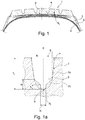
- Fig. 1 are of the usual components of a commercial vehicle tire, a tread 1, a radially located within the tread 1, multilayer, in the shown Four-layer embodiment, belt dressing 2, sections of a carcass insert 3 and an airtight inner layer 4, as well as the axially outer end sections of side walls 5 are shown.
- the bead areas with bead cores, core profiles and further reinforcement layers, optionally provided in the bead areas, are not shown and can be designed in a known manner.
- the tread 1 is provided with four circumferential grooves 6 which run straight in plan view ( Fig. 1b ).
- the circumferential grooves 6 can, however, also run in a zigzag or undulating manner or have sections running in a zigzag or undulating manner.
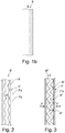
- each circumferential groove 6 on the tread periphery has a width B 1 in the axial direction and is designed in the radial direction to the intended profile depth T 1 .
- the width B 1 of the circumferential groove 6 is in particular 6.0 mm to 25.0 mm and the tread depth T 1 is usually 9.0 mm to 26.0 mm.
- the circumferential groove 6 is designed symmetrically with respect to a central plane E, which is spanned by the radial direction and the circumferential direction.
- the circumferential groove 6 has two mutually opposite groove walls 7 and a groove 8 which runs between the groove walls 7 and at the same time through the deepest point P 1 of the circumferential groove 6.
- the groove walls 7, viewed in cross-section, are each composed of a flat, radially outer flank surface 7a running to the tread periphery and a radially inner sloping surface 7b running to the groove base groove 8 and falling towards it.
- Each radially outer flank surface 7a, viewed in cross section, extends to the radial direction at an angle ⁇ of 0 ° to 15 °, and can therefore also run in the radial direction.
- the inclined surfaces 7b close to the radially inner ends of the flank surfaces at a distance a 1 determined in the radial direction from the level of the deepest point P 1 of up to 60%, in particular from 20% to 40%, of the depth T 1 7a.
- the inclined surfaces 7b, viewed in cross section run to the radial direction at an angle ⁇ of 30 ° to less than 90 °, in particular up to 60 °, and preferably from 40 ° to 50 °.
- the groove base groove 8 viewed in cross section, is U-shaped and has a width b 1 of at least 3.0 mm and at most 40% of the width B 1 of the circumferential groove 6 between its radially outer ends in the axial direction, the width b 1 is preferably 20% to 30% of the width B 1 of the circumferential groove 6. Furthermore, the groove base groove 8 has a depth t 1 of at least 0.3 mm and at most 90% of the mentioned distance a 1 in the radial direction, the depth t 1 in particular 30% to 70%, preferably 45% to 55%, of the distance a is 1 .
- the width b 1 of the groove base groove 8 is constant over the extent of the groove base groove 8, whereby a constant width is to be understood as one which, due to production, can vary in such a way that it is up to 3% larger at the actually widest point of the groove base groove 8 than the actual width at the narrowest point of the groove base groove 8.
- the circumferential groove 6 is preferably designed such that the tread 1 has a sub-profile thickness S 1 (radial profile) between the lowest point P 1 of the circumferential groove 6 and the belt assembly 2. Fig. 1 ) from 1.0 mm to 5.0 mm.
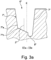
- FIGS. 2 and 3 each show a schematic top view of a section of a circumferential groove 6 ′ or 6 ′′, which variants of the circumferential groove 6 are.
- the two radially inner inclined surfaces 7'b have a continuously repeating increase and decrease in their width determined in cross section over their extension.
- the groove base groove 8 ' has at its radially outer end a constant width b 1 ', which is at least 3.0 mm and at most 40% of the width of the circumferential groove 6 'on the tread periphery.
- the width b 1 of the groove base groove 8 ′ is 20% to 30% of the width of the circumferential groove 6 ′ on the tread periphery.
- the circumferential groove 6 "shown has a zigzag groove basic groove 8" in plan view, which extends between a plurality of triangular projections 9 "in plan view.
- the projections 9" extend to the central plane E of the circumferential groove 6 "and are bounded in the radial direction by inclined surfaces 7 "b of the groove walls 7", the inclined surfaces 7 "b, viewed in cross section, to the radial direction at an angle ⁇ " ( Fig. 3a ) from 30 ° to less than 90 °, in particular up to 60 °, and preferably from 40 ° to 50 °.
- the projections 9" are formed alternately on the groove walls 7 "within the circumferential groove 6", the projections 9 "on one groove wall 7” and the projections 9 “on the other groove wall 7 “are offset in the circumferential direction.
- the groove walls 7 ′′ In the area of the inclined surfaces 7 ′′ b, the groove walls 7 ′′ have flank surfaces 7 ′′ a running to the tread peripheral ( Fig. 3a ).
- the groove base groove 8 with the “outside tips” of its zigzag shape extends to the groove walls 7 "( Fig. 3a ).
- the groove base groove 8 " has a constant width b 1 " over its entire extent, which is at least 3.0 mm and at most 40% of the width of the circumferential groove 6 "at the tread periphery.
- Grooves designed according to the invention are main grooves of a tread, which include, for example, circumferential grooves and, in particular, V-shaped oblique grooves running across the width of the tread.
- An inclined groove is understood to mean a groove which extends at least over the majority of its extent at an angle deviating from the axial direction by more than 45 ° and - in contrast to the circumferential groove - does not run in the circumferential direction or at most one - in comparison to the total extension length. has a short circumferential section.
- oblique grooves extend to the axial direction at an angle of up to 75 °.
Landscapes
- Engineering & Computer Science (AREA)
- Mechanical Engineering (AREA)
- Tires In General (AREA)
Abstract
Description
- Die Erfindung betrifft einen Fahrzeugluftreifen mit einem Laufstreifen mit auf Profiltiefe ausgeführten Hauptrillen, insbesondere Umfangsrillen oder Schrägrillen, wobei die Hauptrillen zwei einander gegenüberliegende Rillenwände und an diese anschließend eine im Querschnitt U-förmige Rillengrundrille aufweisen.
- Es ist bekannt, dass breit und tief ausgeführte Hauptrillen für das Wasserdrainagevermögen sowie die Schneegriffeigenschaften eines Fahrzeugluftreifens von Vorteil sind. Die Rillengründe breiter Hauptrillen sind jedoch besonders anfällig für durch eindringende Fremdkörper, wie Steine und dergleichen, verursachte Schäden. Als Gegenmaßnahme wurde bisher unter anderem eine Erhöhung der Unterprofilstärke des Laufstreifens in Betracht gezogen, wodurch jedoch der Laufstreifen entsprechend dicker wird, was wiederum zu einem höheren Reifengewicht und daher zu einem höheren Rollwiderstand führt.
- Ein Fahrzeugluftreifen der eingangs genannten Art ist beispielsweise aus der
EP 2 567 832 A1 bekannt. Der Laufstreifen dieses Reifens weist Umfangsrillen mit im Querschnitt rechteckigen Rillengrundrillen auf, welche sich aus breiten Umfangsabschnitten und aus schmalen Umfangsabschnitten zusammensetzen, wobei jeweils ein breiter Umfangsabschnitt und ein schmaler Umfangsabschnitt abwechselnd, also alternierend, aufeinanderfolgen. Die Breite eines schmalen Umfangsabschnittes beträgt 25% bis 85% der Breite eines breiten Umfangsabschnittes. Bei einer Ausführungsvariante verläuft die Rillengrundrille über die Erstreckung der Umfangsrille wellenförmig auf und ab, sodass die Rillengrundrille in den schmalen Umfangsabschnitten tiefer ist als in den breiten Umfangsabschnitten. Umfangsrillen mit solchen Rillengrundrillen sollen das Wasserdrainagevermögen des Laufstreifens verbessern, wobei die breiten und schmalen Umfangsabschnitte eine pulsierende Wasserströmung bewirken sollen. Vor allem die breiten Umfangsabschnitte der Rillengrundrillen sind gegenüber einem Eindringen von Steinen ungeschützt, sodass die Gefahr einer Beschädigung des Gummimaterials, beispielsweise die Gefahr des Entstehens von Einrissen gegeben ist. Solche Einrisse können sich sehr schnell fortpflanzen und beeinträchtigen die Haltbarkeit des Laufstreifens. Um dem Entgegenzuwirken ist bei einer Variante vorgesehen, in den breiten Umfangsabschnitten mittig Vorsprünge auszubilden, sogenannte "Steinauswerfer". Diese Vorsprünge behindern jedoch die Wasserdrainage durch die Umfangsrille. - Aus der
DE 2007 016 930 A1 ist ein Fahrzeugluftreifen mit einem Laufstreifen mit Umfangsrillen bekannt, in welchen an den Rillenwänden Vorsprünge ausgebildet sind. Die Vorsprünge sind Teile oder Abschnitte spitzer Körper, deren Basisfläche am Rillengrund der Hauptrille liegt und deren Spitze der Laufstreifenperipherie benachbart ist. Der Abstand der Spitzen der Vorsprünge von der Laufstreifenperiphere beträgt bis zu 30% der Profiltiefe. Solche Vorsprünge sollen insbesondere ein verlässliches Abstoßen von Fremdkörpern, insbesondere von kleinen Steinen, bewirken. - Aus der
WO 2016 003 433 A1 ist ein Fahrzeugluftreifen mit einem Laufstreifen mit reduzierter Unterprofilstärke bekannt. Der Laufstreifen weist Umfangsrillen auf, welche mittig auf ihrem Rillengrund ausgebildete in Umfangsrichtung umlaufende, als Steinauswerfer wirkende Erhebungen aufweisen. - Der Erfindung liegt gegenüber dem aus der
EP 2 567 832 A1 bekannten Fahrzeugluftreifen die Aufgabe zugrunde, das Eindringen von Fremdkörpern, wie Steinen, in die Rillengrundrille zu vermeiden und ein gutes Wasserableitvermögen sicherzustellen bzw. beizubehalten. - Gelöst wird die gestellte Aufgabe erfindungsgemäß dadurch, dass die Rillengrundrille eine konstante Breite von mindestens 3,0 mm und höchstens 40% der Breite der Hauptrille an der Laufstreifenperipherie aufweist, wobei die beiden Rillenwände ebene Flankenflächen und an diese anschließend in Richtung zur Rillengrundrille abfallende Schrägflächen aufweisen, wobei die ebenen Flankenflächen bis zur Laufstreifenperipherie, in radialer Richtung oder unter einem Winkel von bis 10° zur radialen Richtung verlaufen und wobei die Schrägflächen zur radialen Richtung unter einem Winkel, welcher mindestens 30° und weniger als 90° beträgt, verlaufen.
- Die mit konstanter Breite ausgeführte Rillengrundrille unterstützt und ermöglicht gemeinsam mit den Schrägflächen eine verwirbelungsarme Ableitung von Wasser durch die Hauptrillen beim Fahren auf nassem Untergrund, wobei die geneigten Schrägflächen zusätzlich ein Auswerfen von Fremdkörpern begünstigen, sodass diese in die Rillengrundrille nicht eindringen. Dadurch kann radial innerhalb der Rillengrundrille eine geringe Unterprofilstärke vorgesehen werden, wodurch der Rollwiderstand des Fahrzeugluftreifens geringgehalten wird.
- Gemäß einer bevorzugten Variante beträgt die Breite der Rillengrundrille 20% bis 30% der Breite der Hauptrille. Eine Breite von mindestens 20% der Breite der Hauptrille ist im Hinblick auf die Wasserableiteigenschaften der Rillengrundrille von Vorteil, eine Breite von höchstens 30% der Breite der Hauptrille trägt zu einem besonders guten Schutz der Rillengrundrille vor dem Eindringen von Fremdkörpern bei.
- Es ist ferner bevorzugt, wenn der Winkel, unter welchem die Schrägflächen zur radialen Richtung geneigt sind, bis zu 60°, insbesondere 40° bis 50°, beträgt. Auf derart geneigten Schrägflächen wird Wasser besonders zügig in die Rillengrundgrille abgeleitet, wobei die Schrägflächen gleichzeitig die Rillenwände gut abstützen.
- Gemäß einer bevorzugten Ausführungsvariante weist die Rillengrundrille eine Tiefe auf, welche mindestens 0,3 mm und höchstens 90% eines Abstandes beträgt, welcher, im Querschnitt betrachtet, zwischen dem Niveau der tiefsten Punktes der Hauptrille und dem Anschluss der Flankenflächen an die Schrägflächen vorliegt. Vorzugsweise beträgt die Tiefe der Rillengrundrille 30% bis 70%, insbesondere 45% bis 55%, des erwähnten Abstandes. Bei einer Mindesttiefe von 0,3 mm verbleibt eine größere Querschnittsfläche in der Hauptrille erhalten, wodurch die Wasserableitung durch die Hauptrille besonders effektiv ist. Die Maximaltiefe von 90% des erwähnten Abstandes sorgt hingegen für einen besonders guten Schutz vor dem Eindringen von Fremdkörpern.
- Ein vorteilhafter Kompromiss zwischen diesen Effekten lässt sich erreichen, wenn der Abstand zwischen dem Niveau des tiefsten Punktes der Hauptrille und dem Anschluss der Flankenflächen an die Schrägflächen bis zu 60%, insbesondere 20% bis 40%, der Profiltiefe der Hauptrille beträgt.
- Für die Rissbeständigkeit am Rillengrund der Rillengrundrille ist es vorteilhaft, wenn diese, im Querschnitt betrachtet, U-förmig ist.
- Die erwähnte abstützende Wirkung der Schrägflächen ist besonders gut ausgeprägt, wenn die Rillenwände jeweils eine einzige, über die gesamte Erstreckung der Hauptrille verlaufende Schrägfläche aufweisen.
- Eine im Hinblick für die Wasserdrainage besonders vorteilhafte Ausführungsvariante ist dadurch gekennzeichnet, dass die Rillengrundrille zumindest abschnittsweise in Draufsicht gerade verläuft.
- Gemäß einer weiteren bevorzugten Ausführungsvariante weisen die Rillenwände jeweils eine Vielzahl von Schrägflächen auf, welche in radialer Richtung jeweils einen Vorsprung begrenzen, welcher ansonsten von Rillenflanken der Rillengrundrille begrenzt ist. Die Vorsprünge wirken als Steinauswerfer und verringern die Querschnittsfläche der Hauptrille nur in einem derartigen Ausmaß, dass das Wasserdrainagevermögen der Hauptrillen auf gutem Niveau erhalten bleibt.
- Gemäß einer weiteren bevorzugten Ausführungsvariante verläuft die Rillengrundrille in Draufsicht zumindest abschnittsweise wellen- oder zick-zack-förmig. Solche Rillengrundrillen sind besonders gut vor dem Eindringen von Fremdkörpern geschützt.
- Die gemäß der Erfindung bzw. gemäß einer der bevorzugten Ausführungsvarianten ausgeführte Rillengrundrille ermöglicht es ferner, geringe Unterprofilstärken vorzusehen, wodurch der Rollwiderstand reduziert wird und die Produktionskosten der Reifen geringer sind, da weniger Kautschukmischung zur Fertigung der Reifen erforderlich ist. In diesem Zusammenhang ist es von Vorteil, wenn der Laufstreifen zwischen dem tiefsten Punkt der Hauptrille und dem Gürtelverband in radialer Richtung eine Unterprofilstärke von 1,0 mm bis 5,0 mm aufweist.
- Weitere Merkmale, Vorteile und Einzelheiten der Erfindung werden nun anhand der Zeichnung, die schematisch ein Ausführungsbeispiel der Erfindung zeigt, näher beschrieben. Dabei zeigen
-
Fig. 1 einen Querschnitt durch einen Nutzfahrzeugreifen im Bereich des Laufstreifens und Gürtelverbandes mit einer ersten Ausführungsvariante der Erfindung, -
Fig. 1a einen vergrößerten Querschnitt durch eine Umfangsrille des Laufstreifens des Nutzfahrzeugreifens ausFig. 1 , -
Fig. 1b eine schematische Draufsicht auf einen Abschnitt einer Umfangsrille des Laustreifens ausFig. 1 , -
Fig. 2 eine schematische Draufsicht auf einen Abschnitt einer Umfangsrille mit einer zweiten Ausführungsvariante der Erfindung, -
Fig. 3 eine schematische Draufsicht auf einen Abschnitt einer Umfangsrille mit einer dritten Ausführungsvariante der Erfindung und -
Fig. 3a einen vergrößerten Schnitt entlang der Linie IIIa-IIIa derFig. 3 . - Erfindungsgemäß ausgeführte Fahrzeugluftreifen sind insbesondere Nutzfahrzeugreifen in Radialbauart, vorzugsweise für Transporter oder Lastkraftwagen.
- In
Fig. 1 sind von den üblichen Bauteilen eines Nutzfahrzeugreifens ein Laufstreifen 1, ein radial innerhalb des Laufstreifens 1 befindlicher, mehrlagiger, beim gezeigten Ausführungsbeispiel vierlagiger, Gürtelverband 2, Abschnitte einer Karkasseinlage 3 und einer luftdichten Innenschicht 4 sowie die axial äußeren Endabschnitte von Seitenwänden 5 gezeigt. Die Wulstbereiche mit Wulstkernen, Kernprofilen und weiteren, gegebenenfalls in den Wulstbereichen vorgesehenen Verstärkungslagen sind nicht gezeigt und können in bekannter Weise ausgeführt sein. - Der Laufstreifen 1 ist beim gezeigten Ausführungsbeispiel mit vier in Draufsicht gerade verlaufenden Umfangsrillen 6 versehen (
Fig. 1b ). Die Umfangsrillen 6 können jedoch auch zick-zack- oder wellenförmig verlaufen bzw. zick-zack- oder wellenförmig verlaufende Abschnitte aufweisen. - Wie
Fig. 1a zeigt, weist jede Umfangsrille 6 an der Laufstreifenperipherie in axialer Richtung eine Breite B1 auf und ist in radialer Richtung auf die vorgesehene Profiltiefe T1 ausgeführt. Für Nutzfahrzeugreifen beträgt die Breite B1 der Umfangsrille 6 insbesondere 6,0 mm bis 25,0 mm und die Profiltiefe T1 üblicherweise 9,0 mm bis 26,0 mm. WieFig. 1a in Verbindung mitFig. 1b zeigt, ist die Umfangsrille 6 bezüglich einer Mittelebene E, welche von der radialen Richtung und der Umfangsrichtung aufgespannt ist, symmetrisch ausgeführt. GemäßFig. 1a weist die Umfangsrille 6 zwei einander gegenüberliegend verlaufende Rillenwände 7 und eine zwischen den Rillenwänden 7 und gleichzeitig durch den tiefsten Punkt P1 der Umfangsrille 6 verlaufende Rillengrundrille 8 auf. - Die Rillenwände 7 setzen sich, im Querschnitt betrachtet, jeweils aus einer zur Laufstreifenperiphere verlaufenden, ebenen radial äußeren Flankenfläche 7a und einer zur Rillengrundrille 8 verlaufenden und zu dieser abfallenden radial inneren Schrägfläche 7b zusammen. Jede radial äußere Flankenfläche 7a verläuft, im Querschnitt betrachtet, zur radialen Richtung unter einem Winkel α von 0° bis zu 15°, kann daher auch in radialer Richtung verlaufen. Die Schrägflächen 7b schließen in einem gegenüber dem Niveau des tiefsten Punktes P1 in radialer Richtung ermittelten Abstand a1 von bis zu bis 60%, insbesondere von 20% bis 40%, der Tiefe T1 der Umfangsrille 6 an die radial inneren Enden der Flankenflächen 7a an. Ferner verlaufen die Schrägflächen 7b, im Querschnitt betrachtet, zur radialen Richtung unter einem Winkel β von 30° bis kleiner 90°, insbesondere von bis zu 60°, und bevorzugter Weise von 40° bis 50°.
- Die Rillengrundrille 8 ist, im Querschnitt betrachtet, U-förmig, weist zwischen ihren radial äußeren Enden in axialer Richtung eine Breite b1 von mindestens 3,0 mm und höchstens 40% der Breite B1 der Umfangsrille 6 auf, wobei die Breite b1 vorzugsweise 20% bis 30% der Breite B1 der Umfangsrille 6 beträgt. Ferner weist die Rillengrundrille 8 in radialer Richtung eine Tiefe t1 von mindestens 0,3 mm und höchstens 90% des erwähnten Abstandes a1 auf, wobei die Tiefe t1 insbesondere 30% bis 70%, vorzugsweise 45% bis 55%, des Abstandes a1 beträgt. Die Breite b1 der Rillengrundrille 8 ist über die Erstreckung der Rillengrundrille 8 konstant, wobei unter einer konstanten Breite eine solche zu verstehen ist, welche fertigungsbedingt derart variieren kann, dass sie an der tatsächlich breitesten Stelle der Rillengrundrille 8 um bis zu 3% größer ist als die tatsächliche Breite an der schmalsten Stelle der Rillengrundrille 8.
- Bevorzugter Weise ist die Umfangsrille 6 derart ausgeführt, dass der Laufstreifen 1 zwischen dem tiefsten Punkt P1 der Umfangsrille 6 und dem Gürtelverband 2 in radialer Richtung eine Unterprofilstärke S1 (
Fig. 1 ) von 1,0 mm bis 5,0 mm aufweist. -
Fig. 2 und Fig. 3 zeigen jeweils eine schematische Draufsicht auf einen Abschnitt einer Umfangsrille 6' bzw. 6", welche Varianten der Umfangsrille 6 sind. - Die in
Fig. 2 gezeigte Umfangsrille 6' unterscheidet sich von der inFig. 1 gezeigten Umfangsrille 6 dadurch, dass sie eine in Draufsicht wellenförmig verlaufende Rillengrundrille 8' aufweist, sodass Rillenwände 7' mit ebenen radial äußeren Flankenflächen 7'a und einer radial inneren Schrägfläche 7'b vorgesehen sind. Entsprechend dem wellenförmigen Verlauf der Rillengrundrille 8' weisen die beiden radial inneren Schrägflächen 7'b über ihre Erstreckung eine sich kontinuierlich wiederholende Zu- und Abnahme ihrer im Querschnitt ermittelten Breite auf. Die Rillengrundrille 8' weist dabei an ihrem radial äußeren Ende ein konstante Breite b1' auf, welche mindestens 3,0 mm und höchstens 40% der Breite der Umfangsrille 6' an der Laufstreifenperipherie beträgt. Insbesondere beträgt die Breite b1 der Rillengrundrille 8' 20% bis 30% der Breite der Umfangsrille 6' an der Laufstreifenperipherie. - Die in
Fig. 3 gezeigte Umfangsrille 6" weist eine in Draufsicht zick-zack-förmig verlaufende Rillengrundrille 8" auf, welche sich zwischen einer Vielzahl in Draufsicht dreieckiger Vorsprünge 9" erstreckt. Die Vorsprünge 9" reichen beim gezeigten Ausführungsbeispiel bis zur Mittelebene E der Umfangsrille 6" und sind in radialer Richtung von Schrägflächen 7"b der Rillenwände 7" begrenzt, wobei die Schrägflächen 7"b, im Querschnitt betrachtet, zur radialen Richtung unter einem Winkel β" (Fig. 3a ) von 30° bis kleiner 90°, insbesondere von bis zu 60°, und bevorzugter Weise von 40° bis 50°, verlaufen. Entsprechend der Zick-Zack-Form der Rillengrundrille 8" sind die Vorsprünge 9" innerhalb der Umfangsrille 6" alternierend an den Rillenwänden 7" ausgebildet, wobei die Vorsprünge 9" an der einen Rillenwand 7" zu den Vorsprüngen 9" an der anderen Rillenwand 7" in Umfangsrichtung versetzt sind. Im Bereich der Schrägflächen 7"b weisen die Rillenwände 7" zur Laufstreifenperiphere verlaufende Flankenflächen 7"a auf (Fig. 3a ). Zwischen den in Umfangsrichtung jeweils unmittelbar aufeinanderfolgenden Vorsprüngen 9" reicht die Rillengrundrille 8" mit den "außenseitigen Spitzen" ihrer Zick-Zack-Form bis den Rillenwänden 7" (Fig. 3a ). Die Rillengrundrille 8" weist über ihre gesamte Erstreckung eine konstante Breite b1" auf, welche mindestens 3,0 mm und höchstens 40% der Breite der Umfangsrille 6" an der Laufstreifenperipherie beträgt. - Die Erfindung ist auf die beschriebenen und dargestellten Ausführungsbeispiele nicht eingeschränkt.
- Gemäß der Erfindung gestaltete Rillen sind Hauptrillen eines Laufstreifens, zu welchen beispielsweise Umfangsrillen sowie insbesondere V-förmig über die Laufstreifenbreite verlaufende Schrägrillen gehören. Unter einer Schrägrille wird dabei eine Rille verstanden, welche zumindest über den Großteil ihrer Erstreckung unter einem von der axialen Richtung um größer 45° abweichenden Winkel verläuft und - im Gegensatz zur Umfangsrille - nicht in Umfangsrichtung verläuft oder höchstens einen - im Vergleich zur gesamten Erstreckungslänge - kurzen in Umfangsrichtung verlaufenden Abschnitt aufweist. Insbesondere erstrecken sich Schrägrillen zur axialen Richtung unter einem Winkel von bis zu 75°.
-
- 1
- Laufstreifen
- 2
- Gürtelverband
- 3
- Karkasseinlage
- 4
- Innenschicht
- 5
- Seitenwand
- 6, 6', 6"
- Umfangsrille
- 7, 7', 7"
- Rillenwand
- 7a, 7'a, 7"a
- Flankenfläche
- 7b, 7'b, 7"b
- Schrägfläche
- 8, 8', 8"
- Rillengrundrille
- 9
- Vorsprung
- a1
- Abstand
- B1, b1, b1', b1"
- Breite
- E
- Mittelebene
- P1
- tiefster Punkt
- S1
- Unterprofilstärke
- T1, t1
- Tiefe
- α, β, β"
- Winkel
Claims (13)
- Fahrzeugluftreifen mit einem Laufstreifen (1) mit auf Profiltiefe (T1) ausgeführten Hauptrillen (6, 6', 6"), insbesondere Umfangsrillen (6, 6', 6") oder Schrägrillen, wobei die Hauptrillen (6, 6', 6") zwei einander gegenüberliegende Rillenwände (7, 7', 7") und an diese anschließend eine Rillengrundrille (8, 8', 8") aufweisen,
dadurch gekennzeichnet,
dass die Rillengrundrille (8, 8', 8") eine konstante Breite (b1, b1', b1") von mindestens 3,0 mm und höchstens 40% der Breite (B1) der Hauptrille (6, 6', 6") an der Laufstreifenperipherie aufweist, wobei die beiden Rillenwände (7, 7', 7") ebene Flankenflächen (7a, 7'a, 7"a) und an diese anschließend in Richtung zur Rillengrundrille (8, 8', 8") abfallende Schrägflächen (7b, 7'b, 7"b) aufweisen, wobei die ebenen Flankenflächen (7a, 7'a, 7"a) bis zur Laufstreifenperipherie und in radialer Richtung oder unter einem Winkel von bis 10° zur radialen Richtung verlaufen, und wobei die Schrägflächen (7b, 7'b, 7"b) zur radialen Richtung unter einem Winkel (β), welcher mindestens 30° und weniger als 90° beträgt, verlaufen. - Fahrzeugluftreifen nach Anspruch 1, dadurch gekennzeichnet, dass die Breite (b1, b1', b1") der Rillengrundrille (8, 8', 8") 20% bis 30% der Breite (B1) der Hauptrille (6, 6', 6") beträgt.
- Fahrzeugluftreifen nach Anspruch 1 oder 2, dadurch gekennzeichnet, dass der Winkel (β), unter welchem die Schrägflächen (7b, 7'b, 7"b) zur radialen Richtung geneigt sind, bis zu 60°, insbesondere 40° bis 50°, beträgt.
- Fahrzeugluftreifen nach einem der Ansprüche 1 bis 3, dadurch gekennzeichnet, dass die Rillengrundrille (8, 8', 8") eine Tiefe (t1) aufweist, welche mindestens 0,3 mm und höchstens 90% eines Abstandes (a1) beträgt, welcher, im Querschnitt betrachtet, zwischen dem Niveau der tiefsten Punktes (P1) der Hauptrille (6, 6', 6") und dem Anschluss der Flankenflächen (7a, 7'a, 7"a) an die Schrägflächen (7b, 7'b, 7"b) vorliegt.
- Fahrzeugluftreifen nach Anspruch 4, dadurch gekennzeichnet, dass die Tiefe (t1) der Rillengrundrille (8, 8', 8") 30% bis 70%, insbesondere 45% bis 55%, des Abstandes (a1) beträgt, welcher zwischen dem Niveau der tiefsten Punktes (P1) der Hauptrille (6, 6', 6") und dem Anschluss der Flankenflächen (7a, 7'a, 7"a) an die Schrägflächen (7b, 7'b, 7"b) vorliegt.
- Fahrzeugluftreifen nach Anspruch 4 oder 5, dadurch gekennzeichnet, dass der Abstand (a1) zwischen dem Niveau des tiefsten Punktes (P1) der Hauptrille (6, 6', 6") und dem Anschluss der Flankenflächen (7a, 7'a, 7"a) an die Schrägflächen (7b, 7'b, 7"b) bis zu 60%, insbesondere 20% bis 40%, der Profiltiefe (T1) der Hauptrille (6, 6', 6") beträgt.
- Fahrzeugluftreifen nach einem der Ansprüche 1 bis 6, dadurch gekennzeichnet, dass die Rillengrundrille (8, 8', 8"), im Querschnitt betrachtet, U-förmig ist.
- Fahrzeugluftreifen nach einem der Ansprüche 1 bis 7, dadurch gekennzeichnet, dass die Rillenwände (7, 7') jeweils eine einzige, über die gesamte Erstreckung der Hauptrille (6, 6') verlaufende Schrägfläche (7b, 7'b) aufweisen.
- Fahrzeugluftreifen nach einem der Ansprüche 1 bis 8, dadurch gekennzeichnet, dass die Rillengrundrille (8) zumindest abschnittsweise in Draufsicht gerade verläuft.
- Fahrzeugluftreifen nach einem der Ansprüche 1 bis 9, dadurch gekennzeichnet, dass die Rillenwände (7") jeweils eine Vielzahl von Schrägflächen (7"b) aufweisen, welche in radialer Richtung jeweils einen Vorsprung (9") begrenzen, welcher ansonsten von Rillenflanken der Rillengrundrille (8', 8") begrenzt ist.
- Fahrzeugluftreifen nach einem der Ansprüche 1 bis 10, dadurch gekennzeichnet, dass die Rillengrundrille (8) in Draufsicht zumindest abschnittsweise wellenförmig verläuft.
- Fahrzeugluftreifen nach einem der Ansprüche 1 bis 11, dadurch gekennzeichnet, dass die Rillengrundrille (8) in Draufsicht zumindest abschnittsweise zick-zack-förmig verläuft.
- Fahrzeugluftreifen mit einem Gürtelverband (2) nach einem der Ansprüche 1 bis 12, dadurch gekennzeichnet, dass der Laufstreifen (1) zwischen dem tiefsten Punkt (P1) der Hauptrille (6, 6', 6") und dem Gürtelverband (2) in radialer Richtung eine Unterprofilstärke (S1) von 1,0 mm bis 5,0 mm aufweist.
Applications Claiming Priority (1)
| Application Number | Priority Date | Filing Date | Title |
|---|---|---|---|
| DE102018211946.5A DE102018211946A1 (de) | 2018-07-18 | 2018-07-18 | Fahrzeugluftreifen |
Publications (2)
| Publication Number | Publication Date |
|---|---|
| EP3597449A1 true EP3597449A1 (de) | 2020-01-22 |
| EP3597449B1 EP3597449B1 (de) | 2021-03-24 |
Family
ID=66821038
Family Applications (1)
| Application Number | Title | Priority Date | Filing Date |
|---|---|---|---|
| EP19179330.6A Active EP3597449B1 (de) | 2018-07-18 | 2019-06-11 | Fahrzeugluftreifen |
Country Status (2)
| Country | Link |
|---|---|
| EP (1) | EP3597449B1 (de) |
| DE (1) | DE102018211946A1 (de) |
Cited By (1)
| Publication number | Priority date | Publication date | Assignee | Title |
|---|---|---|---|---|
| EP3978274A1 (de) * | 2020-10-01 | 2022-04-06 | Continental Reifen Deutschland GmbH | Nutzfahrzeugreifen |
Families Citing this family (1)
| Publication number | Priority date | Publication date | Assignee | Title |
|---|---|---|---|---|
| DE102021205282A1 (de) * | 2021-05-25 | 2022-12-01 | Continental Reifen Deutschland Gmbh | Fahrzeugluftreifen mit einer Bandage |
Citations (7)
| Publication number | Priority date | Publication date | Assignee | Title |
|---|---|---|---|---|
| DE2951444A1 (de) * | 1978-12-22 | 1980-07-10 | Pirelli | Fahrzeugreifen |
| US4703788A (en) * | 1985-09-17 | 1987-11-03 | Sumitomo Rubber Industries, Ltd. | Tire tread with zig-zag grooves with projections in groove |
| DE102007016930A1 (de) | 2007-04-05 | 2008-10-09 | Continental Aktiengesellschaft | Fahrzeugluftreifen |
| EP2465705A1 (de) * | 2009-09-07 | 2012-06-20 | Bridgestone Corporation | Luftreifen |
| EP2567832A1 (de) | 2010-05-07 | 2013-03-13 | Bridgestone Corporation | Reifen |
| TW201343428A (zh) * | 2012-04-24 | 2013-11-01 | Cheng Shin Rubber Ind Co Ltd | 多重不對稱溝壁之輪胎胎紋結構 |
| WO2016003433A1 (en) | 2014-06-30 | 2016-01-07 | Compagnie Generale Des Etablissements Michelin | Groove ridge for reducing undertread |
-
2018
- 2018-07-18 DE DE102018211946.5A patent/DE102018211946A1/de active Pending
-
2019
- 2019-06-11 EP EP19179330.6A patent/EP3597449B1/de active Active
Patent Citations (7)
| Publication number | Priority date | Publication date | Assignee | Title |
|---|---|---|---|---|
| DE2951444A1 (de) * | 1978-12-22 | 1980-07-10 | Pirelli | Fahrzeugreifen |
| US4703788A (en) * | 1985-09-17 | 1987-11-03 | Sumitomo Rubber Industries, Ltd. | Tire tread with zig-zag grooves with projections in groove |
| DE102007016930A1 (de) | 2007-04-05 | 2008-10-09 | Continental Aktiengesellschaft | Fahrzeugluftreifen |
| EP2465705A1 (de) * | 2009-09-07 | 2012-06-20 | Bridgestone Corporation | Luftreifen |
| EP2567832A1 (de) | 2010-05-07 | 2013-03-13 | Bridgestone Corporation | Reifen |
| TW201343428A (zh) * | 2012-04-24 | 2013-11-01 | Cheng Shin Rubber Ind Co Ltd | 多重不對稱溝壁之輪胎胎紋結構 |
| WO2016003433A1 (en) | 2014-06-30 | 2016-01-07 | Compagnie Generale Des Etablissements Michelin | Groove ridge for reducing undertread |
Cited By (1)
| Publication number | Priority date | Publication date | Assignee | Title |
|---|---|---|---|---|
| EP3978274A1 (de) * | 2020-10-01 | 2022-04-06 | Continental Reifen Deutschland GmbH | Nutzfahrzeugreifen |
Also Published As
| Publication number | Publication date |
|---|---|
| DE102018211946A1 (de) | 2020-01-23 |
| EP3597449B1 (de) | 2021-03-24 |
Similar Documents
| Publication | Publication Date | Title |
|---|---|---|
| EP2892736B1 (de) | Fahrzeugluftreifen | |
| DE102008037497A1 (de) | Fahrzeugluftreifen | |
| EP3256334B1 (de) | Fahrzeugluftreifen | |
| WO2018158021A1 (de) | Fahrzeugluftreifen | |
| EP3009275B1 (de) | Fahrzeugluftreifen | |
| EP3181378A1 (de) | Fahrzeugluftreifen | |
| EP3597449B1 (de) | Fahrzeugluftreifen | |
| DE102019206654A1 (de) | Fahrzeugluftreifen | |
| EP3560735B1 (de) | Nutzfahrzeugreifen | |
| DE102020208125A1 (de) | Fahrzeugluftreifen | |
| EP2138327A1 (de) | Laufflächenprofil für einen Fahrzeugluftreifen | |
| DE102018208349A1 (de) | Fahrzeugluftreifen | |
| EP3256335B1 (de) | Fahrzeugluftreifen | |
| EP2138329A1 (de) | Laufflächenprofil für einen Fahrzeugluftreifen | |
| EP3805019B1 (de) | Fahrzeugluftreifen | |
| EP3009276B1 (de) | Fahrzeugluftreifen | |
| DE102016219017A1 (de) | Fahrzeugluftreifen | |
| EP3789213B1 (de) | Fahrzeugluftreifen | |
| EP3715148B1 (de) | Fahrzeugluftreifen | |
| EP3870461B1 (de) | Fahrzeugluftreifen | |
| EP3310592B1 (de) | Fahrzeugluftreifen | |
| WO2015197211A1 (de) | Fahrzeugluftreifen | |
| WO2023208287A1 (de) | Fahrzeugreifen | |
| EP4140776A1 (de) | Fahrzeugluftreifen | |
| DE102020204072A1 (de) | Fahrzeugluftreifen |
Legal Events
| Date | Code | Title | Description |
|---|---|---|---|
| PUAI | Public reference made under article 153(3) epc to a published international application that has entered the european phase |
Free format text: ORIGINAL CODE: 0009012 |
|
| STAA | Information on the status of an ep patent application or granted ep patent |
Free format text: STATUS: THE APPLICATION HAS BEEN PUBLISHED |
|
| AK | Designated contracting states |
Kind code of ref document: A1 Designated state(s): AL AT BE BG CH CY CZ DE DK EE ES FI FR GB GR HR HU IE IS IT LI LT LU LV MC MK MT NL NO PL PT RO RS SE SI SK SM TR |
|
| AX | Request for extension of the european patent |
Extension state: BA ME |
|
| STAA | Information on the status of an ep patent application or granted ep patent |
Free format text: STATUS: REQUEST FOR EXAMINATION WAS MADE |
|
| 17P | Request for examination filed |
Effective date: 20200722 |
|
| RBV | Designated contracting states (corrected) |
Designated state(s): AL AT BE BG CH CY CZ DE DK EE ES FI FR GB GR HR HU IE IS IT LI LT LU LV MC MK MT NL NO PL PT RO RS SE SI SK SM TR |
|
| GRAP | Despatch of communication of intention to grant a patent |
Free format text: ORIGINAL CODE: EPIDOSNIGR1 |
|
| STAA | Information on the status of an ep patent application or granted ep patent |
Free format text: STATUS: GRANT OF PATENT IS INTENDED |
|
| RAP1 | Party data changed (applicant data changed or rights of an application transferred) |
Owner name: CONTINENTAL REIFEN DEUTSCHLAND GMBH |
|
| INTG | Intention to grant announced |
Effective date: 20201207 |
|
| GRAS | Grant fee paid |
Free format text: ORIGINAL CODE: EPIDOSNIGR3 |
|
| GRAA | (expected) grant |
Free format text: ORIGINAL CODE: 0009210 |
|
| STAA | Information on the status of an ep patent application or granted ep patent |
Free format text: STATUS: THE PATENT HAS BEEN GRANTED |
|
| AK | Designated contracting states |
Kind code of ref document: B1 Designated state(s): AL AT BE BG CH CY CZ DE DK EE ES FI FR GB GR HR HU IE IS IT LI LT LU LV MC MK MT NL NO PL PT RO RS SE SI SK SM TR |
|
| REG | Reference to a national code |
Ref country code: GB Ref legal event code: FG4D Free format text: NOT ENGLISH |
|
| REG | Reference to a national code |
Ref country code: CH Ref legal event code: EP |
|
| REG | Reference to a national code |
Ref country code: IE Ref legal event code: FG4D Free format text: LANGUAGE OF EP DOCUMENT: GERMAN |
|
| REG | Reference to a national code |
Ref country code: DE Ref legal event code: R096 Ref document number: 502019001040 Country of ref document: DE Ref country code: AT Ref legal event code: REF Ref document number: 1374116 Country of ref document: AT Kind code of ref document: T Effective date: 20210415 |
|
| REG | Reference to a national code |
Ref country code: LT Ref legal event code: MG9D |
|
| PG25 | Lapsed in a contracting state [announced via postgrant information from national office to epo] |
Ref country code: HR Free format text: LAPSE BECAUSE OF FAILURE TO SUBMIT A TRANSLATION OF THE DESCRIPTION OR TO PAY THE FEE WITHIN THE PRESCRIBED TIME-LIMIT Effective date: 20210324 Ref country code: BG Free format text: LAPSE BECAUSE OF FAILURE TO SUBMIT A TRANSLATION OF THE DESCRIPTION OR TO PAY THE FEE WITHIN THE PRESCRIBED TIME-LIMIT Effective date: 20210624 Ref country code: FI Free format text: LAPSE BECAUSE OF FAILURE TO SUBMIT A TRANSLATION OF THE DESCRIPTION OR TO PAY THE FEE WITHIN THE PRESCRIBED TIME-LIMIT Effective date: 20210324 Ref country code: GR Free format text: LAPSE BECAUSE OF FAILURE TO SUBMIT A TRANSLATION OF THE DESCRIPTION OR TO PAY THE FEE WITHIN THE PRESCRIBED TIME-LIMIT Effective date: 20210625 Ref country code: NO Free format text: LAPSE BECAUSE OF FAILURE TO SUBMIT A TRANSLATION OF THE DESCRIPTION OR TO PAY THE FEE WITHIN THE PRESCRIBED TIME-LIMIT Effective date: 20210624 |
|
| PG25 | Lapsed in a contracting state [announced via postgrant information from national office to epo] |
Ref country code: LV Free format text: LAPSE BECAUSE OF FAILURE TO SUBMIT A TRANSLATION OF THE DESCRIPTION OR TO PAY THE FEE WITHIN THE PRESCRIBED TIME-LIMIT Effective date: 20210324 Ref country code: RS Free format text: LAPSE BECAUSE OF FAILURE TO SUBMIT A TRANSLATION OF THE DESCRIPTION OR TO PAY THE FEE WITHIN THE PRESCRIBED TIME-LIMIT Effective date: 20210324 Ref country code: SE Free format text: LAPSE BECAUSE OF FAILURE TO SUBMIT A TRANSLATION OF THE DESCRIPTION OR TO PAY THE FEE WITHIN THE PRESCRIBED TIME-LIMIT Effective date: 20210324 |
|
| REG | Reference to a national code |
Ref country code: NL Ref legal event code: MP Effective date: 20210324 |
|
| PG25 | Lapsed in a contracting state [announced via postgrant information from national office to epo] |
Ref country code: NL Free format text: LAPSE BECAUSE OF FAILURE TO SUBMIT A TRANSLATION OF THE DESCRIPTION OR TO PAY THE FEE WITHIN THE PRESCRIBED TIME-LIMIT Effective date: 20210324 |
|
| PG25 | Lapsed in a contracting state [announced via postgrant information from national office to epo] |
Ref country code: SM Free format text: LAPSE BECAUSE OF FAILURE TO SUBMIT A TRANSLATION OF THE DESCRIPTION OR TO PAY THE FEE WITHIN THE PRESCRIBED TIME-LIMIT Effective date: 20210324 Ref country code: LT Free format text: LAPSE BECAUSE OF FAILURE TO SUBMIT A TRANSLATION OF THE DESCRIPTION OR TO PAY THE FEE WITHIN THE PRESCRIBED TIME-LIMIT Effective date: 20210324 Ref country code: CZ Free format text: LAPSE BECAUSE OF FAILURE TO SUBMIT A TRANSLATION OF THE DESCRIPTION OR TO PAY THE FEE WITHIN THE PRESCRIBED TIME-LIMIT Effective date: 20210324 Ref country code: EE Free format text: LAPSE BECAUSE OF FAILURE TO SUBMIT A TRANSLATION OF THE DESCRIPTION OR TO PAY THE FEE WITHIN THE PRESCRIBED TIME-LIMIT Effective date: 20210324 |
|
| PG25 | Lapsed in a contracting state [announced via postgrant information from national office to epo] |
Ref country code: PL Free format text: LAPSE BECAUSE OF FAILURE TO SUBMIT A TRANSLATION OF THE DESCRIPTION OR TO PAY THE FEE WITHIN THE PRESCRIBED TIME-LIMIT Effective date: 20210324 Ref country code: PT Free format text: LAPSE BECAUSE OF FAILURE TO SUBMIT A TRANSLATION OF THE DESCRIPTION OR TO PAY THE FEE WITHIN THE PRESCRIBED TIME-LIMIT Effective date: 20210726 Ref country code: RO Free format text: LAPSE BECAUSE OF FAILURE TO SUBMIT A TRANSLATION OF THE DESCRIPTION OR TO PAY THE FEE WITHIN THE PRESCRIBED TIME-LIMIT Effective date: 20210324 Ref country code: SK Free format text: LAPSE BECAUSE OF FAILURE TO SUBMIT A TRANSLATION OF THE DESCRIPTION OR TO PAY THE FEE WITHIN THE PRESCRIBED TIME-LIMIT Effective date: 20210324 Ref country code: IS Free format text: LAPSE BECAUSE OF FAILURE TO SUBMIT A TRANSLATION OF THE DESCRIPTION OR TO PAY THE FEE WITHIN THE PRESCRIBED TIME-LIMIT Effective date: 20210724 |
|
| REG | Reference to a national code |
Ref country code: DE Ref legal event code: R097 Ref document number: 502019001040 Country of ref document: DE |
|
| PG25 | Lapsed in a contracting state [announced via postgrant information from national office to epo] |
Ref country code: ES Free format text: LAPSE BECAUSE OF FAILURE TO SUBMIT A TRANSLATION OF THE DESCRIPTION OR TO PAY THE FEE WITHIN THE PRESCRIBED TIME-LIMIT Effective date: 20210324 Ref country code: DK Free format text: LAPSE BECAUSE OF FAILURE TO SUBMIT A TRANSLATION OF THE DESCRIPTION OR TO PAY THE FEE WITHIN THE PRESCRIBED TIME-LIMIT Effective date: 20210324 Ref country code: AL Free format text: LAPSE BECAUSE OF FAILURE TO SUBMIT A TRANSLATION OF THE DESCRIPTION OR TO PAY THE FEE WITHIN THE PRESCRIBED TIME-LIMIT Effective date: 20210324 Ref country code: MC Free format text: LAPSE BECAUSE OF FAILURE TO SUBMIT A TRANSLATION OF THE DESCRIPTION OR TO PAY THE FEE WITHIN THE PRESCRIBED TIME-LIMIT Effective date: 20210324 |
|
| PLBE | No opposition filed within time limit |
Free format text: ORIGINAL CODE: 0009261 |
|
| STAA | Information on the status of an ep patent application or granted ep patent |
Free format text: STATUS: NO OPPOSITION FILED WITHIN TIME LIMIT |
|
| PG25 | Lapsed in a contracting state [announced via postgrant information from national office to epo] |
Ref country code: SI Free format text: LAPSE BECAUSE OF FAILURE TO SUBMIT A TRANSLATION OF THE DESCRIPTION OR TO PAY THE FEE WITHIN THE PRESCRIBED TIME-LIMIT Effective date: 20210324 |
|
| 26N | No opposition filed |
Effective date: 20220104 |
|
| REG | Reference to a national code |
Ref country code: BE Ref legal event code: MM Effective date: 20210630 |
|
| PG25 | Lapsed in a contracting state [announced via postgrant information from national office to epo] |
Ref country code: LU Free format text: LAPSE BECAUSE OF NON-PAYMENT OF DUE FEES Effective date: 20210611 |
|
| PG25 | Lapsed in a contracting state [announced via postgrant information from national office to epo] |
Ref country code: IE Free format text: LAPSE BECAUSE OF NON-PAYMENT OF DUE FEES Effective date: 20210611 |
|
| PG25 | Lapsed in a contracting state [announced via postgrant information from national office to epo] |
Ref country code: IS Free format text: LAPSE BECAUSE OF FAILURE TO SUBMIT A TRANSLATION OF THE DESCRIPTION OR TO PAY THE FEE WITHIN THE PRESCRIBED TIME-LIMIT Effective date: 20210724 |
|
| PG25 | Lapsed in a contracting state [announced via postgrant information from national office to epo] |
Ref country code: BE Free format text: LAPSE BECAUSE OF NON-PAYMENT OF DUE FEES Effective date: 20210630 |
|
| PG25 | Lapsed in a contracting state [announced via postgrant information from national office to epo] |
Ref country code: IT Free format text: LAPSE BECAUSE OF FAILURE TO SUBMIT A TRANSLATION OF THE DESCRIPTION OR TO PAY THE FEE WITHIN THE PRESCRIBED TIME-LIMIT Effective date: 20210324 |
|
| REG | Reference to a national code |
Ref country code: CH Ref legal event code: PL |
|
| PG25 | Lapsed in a contracting state [announced via postgrant information from national office to epo] |
Ref country code: LI Free format text: LAPSE BECAUSE OF NON-PAYMENT OF DUE FEES Effective date: 20220630 Ref country code: CH Free format text: LAPSE BECAUSE OF NON-PAYMENT OF DUE FEES Effective date: 20220630 |
|
| PG25 | Lapsed in a contracting state [announced via postgrant information from national office to epo] |
Ref country code: CY Free format text: LAPSE BECAUSE OF FAILURE TO SUBMIT A TRANSLATION OF THE DESCRIPTION OR TO PAY THE FEE WITHIN THE PRESCRIBED TIME-LIMIT Effective date: 20210324 |
|
| PG25 | Lapsed in a contracting state [announced via postgrant information from national office to epo] |
Ref country code: HU Free format text: LAPSE BECAUSE OF FAILURE TO SUBMIT A TRANSLATION OF THE DESCRIPTION OR TO PAY THE FEE WITHIN THE PRESCRIBED TIME-LIMIT; INVALID AB INITIO Effective date: 20190611 |
|
| PGFP | Annual fee paid to national office [announced via postgrant information from national office to epo] |
Ref country code: FR Payment date: 20230628 Year of fee payment: 5 Ref country code: DE Payment date: 20230630 Year of fee payment: 5 |
|
| PGFP | Annual fee paid to national office [announced via postgrant information from national office to epo] |
Ref country code: GB Payment date: 20230622 Year of fee payment: 5 |
|
| REG | Reference to a national code |
Ref country code: DE Ref legal event code: R081 Ref document number: 502019001040 Country of ref document: DE Owner name: CONTINENTAL REIFEN DEUTSCHLAND GMBH, DE Free format text: FORMER OWNER: CONTINENTAL REIFEN DEUTSCHLAND GMBH, 30165 HANNOVER, DE |
|
| PG25 | Lapsed in a contracting state [announced via postgrant information from national office to epo] |
Ref country code: MK Free format text: LAPSE BECAUSE OF FAILURE TO SUBMIT A TRANSLATION OF THE DESCRIPTION OR TO PAY THE FEE WITHIN THE PRESCRIBED TIME-LIMIT Effective date: 20210324 |