EP3703957B1 - Lauffläche für einen schwerlastwagenreifen - Google Patents
Lauffläche für einen schwerlastwagenreifen Download PDFInfo
- Publication number
- EP3703957B1 EP3703957B1 EP17797823.6A EP17797823A EP3703957B1 EP 3703957 B1 EP3703957 B1 EP 3703957B1 EP 17797823 A EP17797823 A EP 17797823A EP 3703957 B1 EP3703957 B1 EP 3703957B1
- Authority
- EP
- European Patent Office
- Prior art keywords
- tread
- stone
- stone ejector
- ejector
- set forth
- Prior art date
- Legal status (The legal status is an assumption and is not a legal conclusion. Google has not performed a legal analysis and makes no representation as to the accuracy of the status listed.)
- Active
Links
Images




Classifications
-
- B—PERFORMING OPERATIONS; TRANSPORTING
- B60—VEHICLES IN GENERAL
- B60C—VEHICLE TYRES; TYRE INFLATION; TYRE CHANGING; CONNECTING VALVES TO INFLATABLE ELASTIC BODIES IN GENERAL; DEVICES OR ARRANGEMENTS RELATED TO TYRES
- B60C11/00—Tyre tread bands; Tread patterns; Anti-skid inserts
- B60C11/03—Tread patterns
- B60C11/0302—Tread patterns directional pattern, i.e. with main rolling direction
-
- B—PERFORMING OPERATIONS; TRANSPORTING
- B60—VEHICLES IN GENERAL
- B60C—VEHICLE TYRES; TYRE INFLATION; TYRE CHANGING; CONNECTING VALVES TO INFLATABLE ELASTIC BODIES IN GENERAL; DEVICES OR ARRANGEMENTS RELATED TO TYRES
- B60C11/00—Tyre tread bands; Tread patterns; Anti-skid inserts
- B60C11/02—Replaceable treads
-
- B—PERFORMING OPERATIONS; TRANSPORTING
- B60—VEHICLES IN GENERAL
- B60C—VEHICLE TYRES; TYRE INFLATION; TYRE CHANGING; CONNECTING VALVES TO INFLATABLE ELASTIC BODIES IN GENERAL; DEVICES OR ARRANGEMENTS RELATED TO TYRES
- B60C11/00—Tyre tread bands; Tread patterns; Anti-skid inserts
- B60C11/03—Tread patterns
- B60C11/0306—Patterns comprising block rows or discontinuous ribs
-
- B—PERFORMING OPERATIONS; TRANSPORTING
- B60—VEHICLES IN GENERAL
- B60C—VEHICLE TYRES; TYRE INFLATION; TYRE CHANGING; CONNECTING VALVES TO INFLATABLE ELASTIC BODIES IN GENERAL; DEVICES OR ARRANGEMENTS RELATED TO TYRES
- B60C11/00—Tyre tread bands; Tread patterns; Anti-skid inserts
- B60C11/03—Tread patterns
- B60C11/0306—Patterns comprising block rows or discontinuous ribs
- B60C11/0309—Patterns comprising block rows or discontinuous ribs further characterised by the groove cross-section
-
- B—PERFORMING OPERATIONS; TRANSPORTING
- B60—VEHICLES IN GENERAL
- B60C—VEHICLE TYRES; TYRE INFLATION; TYRE CHANGING; CONNECTING VALVES TO INFLATABLE ELASTIC BODIES IN GENERAL; DEVICES OR ARRANGEMENTS RELATED TO TYRES
- B60C11/00—Tyre tread bands; Tread patterns; Anti-skid inserts
- B60C11/03—Tread patterns
- B60C11/032—Patterns comprising isolated recesses
-
- B—PERFORMING OPERATIONS; TRANSPORTING
- B60—VEHICLES IN GENERAL
- B60C—VEHICLE TYRES; TYRE INFLATION; TYRE CHANGING; CONNECTING VALVES TO INFLATABLE ELASTIC BODIES IN GENERAL; DEVICES OR ARRANGEMENTS RELATED TO TYRES
- B60C11/00—Tyre tread bands; Tread patterns; Anti-skid inserts
- B60C11/03—Tread patterns
- B60C11/04—Tread patterns in which the raised area of the pattern consists only of continuous circumferential ribs, e.g. zig-zag
- B60C11/042—Tread patterns in which the raised area of the pattern consists only of continuous circumferential ribs, e.g. zig-zag further characterised by the groove cross-section
- B60C11/047—Tread patterns in which the raised area of the pattern consists only of continuous circumferential ribs, e.g. zig-zag further characterised by the groove cross-section the groove bottom comprising stone trapping protection elements, e.g. ribs
-
- B—PERFORMING OPERATIONS; TRANSPORTING
- B60—VEHICLES IN GENERAL
- B60C—VEHICLE TYRES; TYRE INFLATION; TYRE CHANGING; CONNECTING VALVES TO INFLATABLE ELASTIC BODIES IN GENERAL; DEVICES OR ARRANGEMENTS RELATED TO TYRES
- B60C11/00—Tyre tread bands; Tread patterns; Anti-skid inserts
- B60C11/03—Tread patterns
- B60C11/13—Tread patterns characterised by the groove cross-section, e.g. for buttressing or preventing stone-trapping
- B60C11/1353—Tread patterns characterised by the groove cross-section, e.g. for buttressing or preventing stone-trapping with special features of the groove bottom
-
- B—PERFORMING OPERATIONS; TRANSPORTING
- B60—VEHICLES IN GENERAL
- B60C—VEHICLE TYRES; TYRE INFLATION; TYRE CHANGING; CONNECTING VALVES TO INFLATABLE ELASTIC BODIES IN GENERAL; DEVICES OR ARRANGEMENTS RELATED TO TYRES
- B60C11/00—Tyre tread bands; Tread patterns; Anti-skid inserts
- B60C11/03—Tread patterns
- B60C2011/0337—Tread patterns characterised by particular design features of the pattern
- B60C2011/0339—Grooves
- B60C2011/0341—Circumferential grooves
- B60C2011/0346—Circumferential grooves with zigzag shape
-
- B—PERFORMING OPERATIONS; TRANSPORTING
- B60—VEHICLES IN GENERAL
- B60C—VEHICLE TYRES; TYRE INFLATION; TYRE CHANGING; CONNECTING VALVES TO INFLATABLE ELASTIC BODIES IN GENERAL; DEVICES OR ARRANGEMENTS RELATED TO TYRES
- B60C11/00—Tyre tread bands; Tread patterns; Anti-skid inserts
- B60C11/03—Tread patterns
- B60C2011/0337—Tread patterns characterised by particular design features of the pattern
- B60C2011/0339—Grooves
- B60C2011/0341—Circumferential grooves
- B60C2011/0348—Narrow grooves, i.e. having a width of less than 4 mm
-
- B—PERFORMING OPERATIONS; TRANSPORTING
- B60—VEHICLES IN GENERAL
- B60C—VEHICLE TYRES; TYRE INFLATION; TYRE CHANGING; CONNECTING VALVES TO INFLATABLE ELASTIC BODIES IN GENERAL; DEVICES OR ARRANGEMENTS RELATED TO TYRES
- B60C11/00—Tyre tread bands; Tread patterns; Anti-skid inserts
- B60C11/03—Tread patterns
- B60C11/12—Tread patterns characterised by the use of narrow slits or incisions, e.g. sipes
- B60C11/1204—Tread patterns characterised by the use of narrow slits or incisions, e.g. sipes with special shape of the sipe
- B60C2011/1209—Tread patterns characterised by the use of narrow slits or incisions, e.g. sipes with special shape of the sipe straight at the tread surface
-
- B—PERFORMING OPERATIONS; TRANSPORTING
- B60—VEHICLES IN GENERAL
- B60C—VEHICLE TYRES; TYRE INFLATION; TYRE CHANGING; CONNECTING VALVES TO INFLATABLE ELASTIC BODIES IN GENERAL; DEVICES OR ARRANGEMENTS RELATED TO TYRES
- B60C11/00—Tyre tread bands; Tread patterns; Anti-skid inserts
- B60C11/03—Tread patterns
- B60C11/13—Tread patterns characterised by the groove cross-section, e.g. for buttressing or preventing stone-trapping
- B60C11/1353—Tread patterns characterised by the groove cross-section, e.g. for buttressing or preventing stone-trapping with special features of the groove bottom
- B60C2011/1361—Tread patterns characterised by the groove cross-section, e.g. for buttressing or preventing stone-trapping with special features of the groove bottom with protrusions extending from the groove bottom
-
- B—PERFORMING OPERATIONS; TRANSPORTING
- B60—VEHICLES IN GENERAL
- B60C—VEHICLE TYRES; TYRE INFLATION; TYRE CHANGING; CONNECTING VALVES TO INFLATABLE ELASTIC BODIES IN GENERAL; DEVICES OR ARRANGEMENTS RELATED TO TYRES
- B60C2200/00—Tyres specially adapted for particular applications
- B60C2200/06—Tyres specially adapted for particular applications for heavy duty vehicles
Definitions
- the subject matter of the present invention relates to a tire with a sculpture feature for the reduction of abnormal tread wear. More particularly, the present application involves a tire with a stone ejector that has a sloped upper surface that provides a coupling force that reduces irregular tread wear.
- a sacrificial rib can be incorporated into the tread architecture to delay the onset of irregular wear.
- this feature is sensitive to curbing aggression and its use may not be practical outside of North American long haul applications.
- Other sculptural features that can combat irregular wear include microsipes and inclined microsipes. These are small grooves that extend generally in the lateral, width direction of the tire. Unfortunately, these features are unusable in severe usage applications due to aggression concerns. Aggression on tires is a concern in growing or emerging markets that feature roadways that subject the tire to more severe usage that functions to tear up and wear down the tread at a higher rate than roads that are smoother and in better condition.
- Stone ejectors are sculptural features of tires that are located in grooves of the tread that function to remove stones from the grooves and prevent stones from drilling into the belts and carcass of the tire.
- the stone ejectors are blocks of rubber at the bottom of the grooves and generally do not extend all the way to the upper surface of the tread, at least not when the tire is new.
- the stone ejectors work by flexing or compressing in and out of the contact patch as the tire rotates in order to push stones present within the groove out of the groove.
- stone ejectors do not function to decrease abnormal wear in tires. As such, there remains room for variation and improvement within the art.
- the present invention provides for an inclined stone ejector 18 that provides a coupling force that reduces or eliminates irregular wear.
- This coupling force is produced by including an inclined upper surface 24 on the stone ejector 18 that is oriented in the direction of rotation of the tire 12.
- the stone ejector 18 creates a coupling force x/z that mimics forces generated by other, less robust sculptural features such as sacrificial ribs, micro sipes, and inclined micro sipes.
- x is the forward/rolling component
- z is the vertical component of force.
- Fig. 1 shows a tire 12 that is a heavy duty truck tire 12.
- the tire 12 is not designed for nor used with a car, motorcycle, or light truck (payload capacity less than 4,000 pounds), but is instead designed for and used with heavy duty trucks such as 18 wheelers, garbage trucks, or box trucks.
- the tire 12 may be a steer tire, a drive tire, a trailer tire, or an all position tire.
- the tire 12 includes a carcass 54 onto which a tread 10 is disposed thereon.
- the central axis 56 of the tire 12 extends through the center of the carcass 54, and the axial direction 58 of the tire 12 is parallel to the central axis 56.
- the axial direction 58 can also be referred to and known as the inboard/outboard direction 58.
- the radial direction 60 of the tire 12 is perpendicular to the central axis 56, and the tread 10 is located farther from the central axis 56 in the radial direction 60 than the carcass 54.
- the tread 10 extends all the way around the carcass 54 in the circumferential direction 62 of the tire 12 and circles the central axis 56 360 degrees.
- the tread 10 features five ribs that are separated by four longitudinal grooves that extend in the circumferential direction 62.
- the ribs and grooves may extend completely around the tire 12 in the circumferential direction 62.
- the five ribs can be classified as a central rib, two intermediate ribs, and two shoulder ribs.
- Fig. 1 only one of the intermediate ribs 66 is labeled, and this intermediate rib 66 is located next to the only labeled shoulder rib 48.
- a longitudinal groove 14 separates the intermediate rib 66 from the shoulder rib 48.
- the shoulder rib 48 may be a sacrificial rib in some embodiments.
- the ribs can each be made up of a number of tread blocks that can have various shapes, sizes, and configurations. The inclusion of these architectural features gives the tread 10 different performance properties in use.
- the tread 10 may include certain structural features that can reduce abnormal wear.
- One such structural feature shown with reference to Fig. 1 may be directional sipes that extend across the tread blocks of the ribs in the axial direction 58.
- Stone ejectors 18 are located in the groove 14 between the intermediate rib 66 and the shoulder rib 48.
- the stone ejectors 18 extend along the entire length of the groove 14 in the circumferential direction 62 and thus extend 360 degrees around the central axis 56.
- the stone ejectors 18 are spaced from one another in the circumferential direction 62 and are likewise spaced from the ribs 48, 66 in the axial direction 58.
- the stone ejectors 18 may engage the intermediate rib 66, and/or the shoulder rib 48.
- the tire 10 also includes another groove located adjacent the other shoulder rib and stone ejectors 18 are likewise present within this other groove.
- the grooves between the center rib and the intermediate ribs do not include stone ejectors 18. However, in other embodiments they may be present within these grooves as well.
- the tread 10 having the stone ejectors 18 may alternatively be provided as a retread band 64 that may be subsequently attached to a carcass 54 through a retread process.
- An example of a retread band 64 is illustrated in Fig. 2 that has five ribs and four grooves that span across the tread 10 in the axial direction 58 which is the inboard/outboard direction 58 of the tread 10.
- Stone ejectors 18 are located in the grooves between the shoulder ribs and the intermediate ribs.
- One of the intermediate ribs 66 is labeled and it along with the adjacent labeled shoulder rib 48 partially defines the labeled groove 14.
- the labeled groove 14 is further defined at its bottom by the tread 10 and is open at its top.
- the retread band 64 is directional in that it has a specified rolling direction 68 in which at least the stone ejectors 18 are oriented. There may or may not be other directional features on the tread 10 that likewise cause the retread band 64 to be directional above and beyond just the stone ejectors 18.
- the stone ejectors 18 are arranged so that their front sides 20 are oriented towards the direction of the rolling direction 68, and so that their oppositely disposed back sides 22 are oriented away from the rolling direction 68.
- the stone ejectors 18 have an outboard side 42 that directly faces the shoulder rib 48, and an inboard side 40 that directly faces the intermediate rib 66.
- the upper surface 24 of the stone ejectors 18 are visible and are inclined relative to the bottom 16 of the grooves 14, although this cannot be easily distinguished in Fig. 2 .
- the stone ejectors 18 are spaced from the shoulder rib 48 and the intermediate rib 66 and are free from contact with both of these ribs 48, 66.
- the stone ejector 18 may engage the intermediate rib 66 and/or the shoulder rib 48.
- the shoulder rib 48 may be a sacrificial rib in certain embodiments.
- the stone ejectors 18 could likewise or alternatively be within any other groove or grooves of the tread 10, such as the grooves formed between the center rib and the adjacent intermediate ribs.
- the retread band 64 with the tread 10 may be of any length and width and can be crafted for tires 12 of varying sizes.
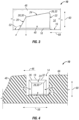
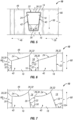
- Figs. 3-5 illustrate a stone ejector 18 in accordance with one exemplary embodiment that features an inclined upper surface 24.
- the stone ejector 18 extends upwards from the bottom 16 of the groove 14.
- the tread 10 is new tread and the stone ejector 18 extends upwards in the radial direction 60 to a point that is below the extension of the shoulder rib 48 in the radial direction 60.
- the stone ejector 18 will not engage the ground 70 as it is below the upper surfaces of the shoulder ribs 48 and intermediate ribs 66.
- the stone ejector 18 in such instances will not impact the problem of abnormal wear.
- the base of the stone ejector 18 has fillets that join the bottom 16 of the groove 14 formed by the tread 10. The fillets need not be present in other embodiments.
- the stone ejector 18 has a front side 20 that is angled relative to the radial direction 60.
- the front side 20 extends at an angle 52 to the radial direction 60 such that the front side 20 extends from the bottom 16 to the upper surface 24 at an angle 52.
- Angle 52 is an obtuse angle and may be various degrees in different versions of the stone ejector 18.
- angle 52 can be from 110-120 degrees, from 120-130 degrees, from 130-140 degrees, from 140-150 degrees, or up to 160 degrees in accordance with different exemplary embodiments.
- the angle 52 may be 102 degrees. Although described as being an obtuse angle 52, in other versions of the stone ejector 18, angle 52 can be an acute angle or a right angle.
- the front side 20 is a flat surface.
- the stone ejector 18 has a back surface 22 that is likewise flat and that extends outward in the radial direction 60 from the bottom 16.
- the back surface 22 is oriented at a ninety degree angle to the bottom 16.
- the rolling direction 68 is illustrated in Fig. 3 and is the direction the tire 12 rotates.
- the front side 20 is before the back side 22 such that the front side 20 will enter the contact patch before the back side 22 when the tire 12 rotates.
- the upper surface 24 of the stone ejector 18 extends at different distances from the bottom 16 in the radial direction 60.
- a first location 26 on the upper surface 24 is located closer to the back side 22 than a second location 28 on the upper surface.
- the second location 28 is located closer to the front side 20 than the first location 26 is to the front side 20.
- the first location 26 is located farther from the bottom 16 in the radial direction 60 than the second location 28.
- the upper surface 24 at the first location 26 is farther from the bottom 16 than is the upper surface 24 at the second location 28.
- the front edge 30 of the upper surface 24 engages the front side 20, and the back edge 32 of the upper surface 24 engages the back side 22.
- the first location 26 is located at the back edge 32, and the second location 28 is located at the front edge 30.
- the first and second locations 26, 28 need not be at the front and back edges 30, 32.
- the upper surface 24 is continuously inclined from the front edge 30 to the back edge 32 so that at all points closer to the back edge 32 are farther from the bottom 16 in the radial direction 60 than points closer to the front edge 30.
- the first location 26 at the back edge 32 may be 1 millimeter farther from the bottom 16 in the radial direction 60 than the second location 28 at the back edge 32 is to the bottom 16 in the radial direction 60.
- the upper surface 24 need not be continuously inclined all the way from the front edge 30 to the back edge 32, but could have some portions located closer to the back side 22 closer to the bottom 16 in the radial direction 60 than portions closer to the front side 20. However, the upper surface 24 will still have somewhere a first location 26 closer to the back side 22, and a second location 28 closer to the front side 20, where the distance in the radial direction 60 from the bottom 16 to the upper surface 24 is longer to the first location 26 than to the second location 28.
- the upper surface 24 when inclined can be any amount of inclination, so long as it is greater than zero degrees and not a flat surface parallel to the bottom 16.
- FIG. 3 , 6 and 7 show the bottom 16 being flat.
- the tread 10 could be a retread and thus in fact have a flat bottom 16.
- the tread 10 can be in a tire 12 which is a round object.
- the bottom 16 may be curved as well, and the stone ejector 18 can also exhibit some amount of curvature due to the roundness of the tire 12.
- the figures illustrate the bottom 16 and the stone ejectors 18 being flat without this curvature for sake of clarity in the description.
- the stone ejector 18 has an inboard side 40 that directly faces the intermediate rib 66, and an outboard side 42 that directly faces the shoulder rib 48.
- the direct facing means that no other component is located between the two facing components.
- the inboard side 40 is a flat surface and is inclined in the axial direction 58.
- the outboard side 42 is also a flat surface inclined in the axial direction 58 an identical magnitude as the inboard side 40.
- the outboard side 42 is free from engagement with the shoulder rib 48, and the inboard side 40 is free from engagement with the intermediate rib 66.
- the back side 22 extends a longer distance in the axial direction 58 than does the front side 20 so that the back side 22 is wider than the front side 20.
- the inboard side 40 extends in the inboard direction upon its extension from the front side 20 to the back side 22.
- the outboard side 42 extends in the outboard direction 46 upon its extension from the front side 20 to the back side 22.
- the inboard and outboard sides 40, 42 may be asymmetrical in other embodiments.
- Figs. 3-5 show only a single one of the stone ejectors 18, and only portions of the intermediate rib 66 and the shoulder rib 48 and that the tread 10 can include multiple ones of the stone ejectors 18 and other sections of the tread 10.
- Other figures in the drawings likewise only disclose portions of the tread 10 and not all of the tread 10.
- the back side 22 is oriented at an angle 50 to the bottom 16 and is an obtuse angle such that the back side 22 extends from the back edge 32 to the bottom 16 in a direction away from the rolling direction 68.
- Angle 50 may be from 91-100 degrees, from 100-110 degrees, from 110-120 degrees, from 130-140 degrees, or up to 150 degrees in accordance with various exemplary embodiments.
- the two stone ejectors 18 in Fig. 7 have angles 50 that are of different magnitudes so that the back sides 22 are oriented at different inclinations to the bottom 16.
- the angles 50 could be the same in other arrangements so that all of the stone ejectors 18 are identical to one another.
- Fig. 8 shows another embodiment of the stone ejector 18 that again has a front side 20 and a back side 22 that extend ninety degrees to the bottom 16.
- the upper surface 24 has a first location 26 that is closer to the back side 22 than a second location 28.
- the second location 28 is closer to the front side 20 than the first location 26.
- the upper surface 24 at the first location 26 extends a farther distance from the bottom 16 in the radial direction 60 than does the upper surface 24 at the second location 28.
- the first location 26 is spaced from the back edge 32 in the rolling direction 68 and is not located at the back edge 32.
- the second location 28 is spaced from the front edge 30 in the rolling direction 68 and is not located at the front edge 30.
- the upper surface 24 can be arranged in various embodiments so that it does not move closer towards the bottom 16 in the radial direction 60 at any point or points upon extension from the front edge 30 to the back edge 32.
- the upper surface 24 may have the same distance from the bottom 16 in the radial direction 60 at different locations in the rolling direction 68, for instance all of the points on the upper surface 24 at a single step are at different locations in the rolling direction 68 but are all the same distance in the radial direction 60, nowhere does the upper surface 24 move closer to the bottom 18 upon extension of the upper surface 24 from the front side 20 to the back side 22.
- the embodiment of the stone ejector 18 in Figs. 10-12 is Y-shaped, and this is but one example of the various shapes the stone ejector 18 can take. In other arrangements, the stone ejector 18 can be X-shaped, circular in shape, triangular in shape, or can be variously shaped. It is to be understood that the shapes of the stone ejectors 18 illustrated and described in the present application are only examples and that others are possible in accordance with other exemplary embodiments of the tread 10.
- a cross-section view of portions of a tread 10 and carcass 54 are shown that illustrate another exemplary embodiment of the tire 12.
- the stone ejector 18 is made up of a material that is different than the material making up an undertread layer 72 of the tire 12.
- the carcass 54 is below this undertread layer 72 and includes belts and may be made of a different material than the undertread layer 72 and the stone ejector 18.
- the stone ejector 18 is made of a different material than the shoulder rib 48, and is made of a different material than the intermediate rib 66. In some instances, the intermediate rib 66 and the shoulder rib 48 can be made of the same material as one another.
- the stone ejector 18 has a different hysteresis value than the ribs 48, 66 and a different hysteresis value than the undertread layer 72.
- the stone ejector 118 has a higher hysteresis value than the shoulder rib 48, the intermediate rib 66, and the undertread layer 72.
- test specimen consisting of two cylindrical pellets each 2 millimeters thick and one centimeter in diameter
- the test specimen is made from samples taken from a tire mid-way up the height of the layer concerned as close as possible to the region of the equatorial plane in a region that is thick enough to be able to form the test specimen
- the specimen being subjected to simple alternating sinusoidal shear loadings at a frequency of 10 Hz, at a temperature of 60° C.
- the sweep covers amplitude of deformation from 0.1% to 25% peak to peak (on the outbound cycle) then from 25% to 1% peak to peak (on the return cycle).
- the results that are used here are the loss factor tan( ⁇ ) and the complex dynamic shear modulus.
- the complex dynamic shear modulus is denoted "G*25" in reference to the 25% strain applied during the test.
- maximum value of tan ⁇ that is observed is denoted "max tan( ⁇ )".
- the max tan( ⁇ ) of the shoulder rib 48 and the intermediate rib 66 may be from 0.06-0.15, and the max tan( ⁇ ) of the stone ejector 18 may be from 0.12-0.27, in which the max tan( ⁇ ) of the stone ejector 18 is higher than the max tan( ⁇ ) of the ribs 48, 66.
- the max tan( ⁇ ) of the undertread layer 72 is from 0.06-0.15 and the max tan( ⁇ ) of the stone ejector 18 is higher than the undertread layer and is greater than 0.15 and less than 0.27.
- the max tan( ⁇ ) of the undertread layer 72 is the same as the max tan( ⁇ ) of the ribs 66, 48, and this max tan( ⁇ ) is less than the max tan( ⁇ ) of the stone ejector 18.
- the max tan( ⁇ ) of the stone ejector 18 can be the same as, greater than, or less than the max tan( ⁇ ) of the undertread layer 72, the shoulder rib 48, the intermediate rib 66, carcass 54, or any other portion of the tire 10, and the material making up the stone ejector 18 may be the same as or different from the material making up the undertread layer 72, shoulder rib 48, intermediate rib 66, carcass 54 or any other portion of the tire 12.
- the max tan( ⁇ ) of the stone ejector 18 may be any value in accordance with various exemplary embodiments.
- the undertread layer 72 may have the same max tan( ⁇ ) as the ribs 66, 48 in certain embodiments.
- the complex shear modulus for 25% strain (G*25) at 60°C may be selected so that the G*25 of the stone ejector 18 is greater than the G*25 of the intermediate rib 66 and the G*25 of the shoulder rib 48.
- the G*25 of the stone ejector 18 can be greater than the G*25 of the undertread layer 72.
- the G*25 can be used to gauge the rigidity of the material, and the stone ejector 18 may be selected so that it is more rigid than the shoulder rib 48, the undertread layer 72, and the intermediate rib 66.
- the G*25 of the stone ejector 18 may be the same as that of the shoulder rib 48, the undertread layer 72, or the intermediate rib 66. In some embodiments, the G*25 of the stone ejector 18, the undertread layer 72, the intermediate rib 66, and the shoulder rib 48 are from 1.5-1.8 MPa, with the stone ejector 18 being the highest or tied for the highest among these components.
- the G*25 of the stone ejector 18 may be any number in other exemplary embodiments.
- the stone ejector 18 may be provided with a high G*25 and thus a greater rigidity than other tread 10 components because a more rigid stone ejector 18 may generate greater x/z coupling and function to better reduce abnormal wear.
- the higher G*25 with the stone ejector 18 may also provide a better wear speed differential so that the stone ejector 18 wears slower than the rest of the useful tread 10 such as the shoulder rib 48 and the intermediate rib 66.
- the length, width, and height of the stone ejector 18 can be varied in order to achieve different performance properties. Also, the degree of slope of the upper surface 24 can be varied to again achieve different performance characteristics of the stone ejector 18.
- the material that changes hysteresis and/or G*25 of the stone ejector 18 versus other components of the tread 10 can be present in order to enhance these effects, or may not be present in accordance with different exemplary embodiments.
- the upper surface 24 having the different elevations generates forces in the contact patch of the tire 12 to fight irregular wear, and the presence of the stone ejector 18 still maintains the original intent of stone ejectors in preventing stone damage to the tire 12.
- the tire 12 that has the stone ejectors 18 of the present disclosure are all directional tires 12.
- the G*25 of the stone ejector 18 can be the same as, greater than, or less than the G*25 of the undertread layer 72, the shoulder rib 48, the intermediate rib 66, the carcass 54, or any other portion of the tire 10.
- the G*25 of the undertread layer 72 may be the same as the G*25 of the shoulder rib 48 and the intermediate rib 66 in certain exemplary embodiments.
- the material making up the stone ejector 18 may be the same as or different from the material making up the shoulder rib 48, intermediate rib 66, undertread layer 72, carcass 54, or any other portion of the tire 12.
- the heel to toe aspect of the upper surface 24 generates a coupling force that in turn results in better irregular wear resistance.
- the stone ejector 18 engaging the ground 70 is illustrated with reference to Fig. 14 that shows the stone ejector 18 deformed in the contact patch and the entire upper surface 24 engaging the ground 70.
- the rolling direction 68 is the direction the entire tire 12 is moving, but it is to be understood that different parts of the tire 12 move in different directions when rolling.
- the stone ejector 18 illustrated in Fig. 14 is in fact moving in a direction opposite to the rolling direction 68 due to it being on the bottom of the tire 12 contacting the ground 70.
- the front side 20 and the back side 20 are curved in shape upon engaging the ground 70 and being subjected to driving and weight forces.
- the orientation of the upper surface 24 as previously discussed presents a generally inclined surface to the ground 70 resulting in x and z force components to be generated on the stone ejector 18.
- the driving force is applied to the adjacent shoulder rib 48 and this applied driving force to this rib 48 results in a decrease in abnormal wear of the shoulder rib 48.
- the stone ejector 18 could be used to prolong the coupling effect that currently degrades linearly with tread 10 wear.
- the tire 12 may initially get its directionality from other structural features such as micro sipes, and may remain protected even when these structural features have lost their effectiveness from tread 10 wear as the stone ejectors 18 can begin to contribute to abnormal wear minimization or elimination.
- the stone ejectors 18 protect against aggression by preventing stones from drilling into the tread 10, and the upper surface 24 orientation protects from irregular wear.
- the tire 12 with the tread 10 having the stone ejector 18 can be an original equipment manufactured tire that is produced and goes onto a new vehicle.
- the tire 12 may also be a retreaded tire in which a used carcass 54 is fitted with a new tread 10 that includes the stone ejector 18.
Landscapes
- Engineering & Computer Science (AREA)
- Mechanical Engineering (AREA)
- Tires In General (AREA)
Claims (15)
- Lauffläche (10) für einen Schwerlastreifen (12), wobei die Lauffläche insofern laufrichtungsgebunden ist, als sie eine bestimmte Abrollrichtung (68) aufweist, wobei die Lauffläche umfasst:eine Längsnut (14), die einen Boden (16) hat; undeinen Steinauswerfer (18), der in der Nut (14) angeordnet ist, die sich vom Nutboden (16) nach oben erstreckt, wobei der Steinauswerfer (18) eine Vorderseite (20) und eine Rückseite (22) aufweist, wobei der Steinauswerfer (18) eine obere Fläche (24) aufweist, die sich in unterschiedlichen Abständen an verschiedenen Stellen auf der oberen Fläche (24) nach oben erstreckt, sodass eine erste Stelle (26) auf der oberen Fläche (24) näher an der Rückseite (22) angeordnet ist und sich über eine längere Strecke nach oben erstreckt, als eine zweite Stelle (28) auf der oberen Fläche (24), die sich näher an der Vorderseite (20) befindet, wobei die Vorderseite (20) in der Rollrichtung (68) ausgerichtet ist und wobei die Hinterseite (22) von der Rollrichtung (68) weg ausgerichtet ist;dadurch gekennzeichnet, dass die Lauffläche (10) ferner umfasst:
einen nachfolgenden Steinauswerfer (18), der in einer Umfangsrichtung (62) unmittelbar auf den Steinauswerfer (18) folgt, wobei zwischen dem Steinauswerfer (18) und dem nachfolgenden Steinauswerfer (18) ein Zwischenraum vorhanden ist, wobei der nachfolgende Steinauswerfer (18) die gleiche Form wie der Steinauswerfer (18) hat und eine nachfolgende Steinauswerferrückseite (22) aufweist, die sich über eine längere Strecke nach oben erstreckt, als eine nachfolgende Steinauswerfervorderseite (20), sodass der nachfolgende Steinauswerfer (18) in der Umfangsrichtung (62) die gleiche Ausrichtung wie der Steinauswerfer (18) hat. - Lauffläche (10) nach Anspruch 1, wobei sich die zweite Stelle (28) an einer Vorderkante (30) der oberen Fläche (24) befindet, die an die Vorderseite (20) grenzt, wobei sich die erste Stelle (26) an einer hinteren Kante (32) der oberen Fläche (24) befindet, die an die Rückseite (22) grenzt, wobei die obere Fläche (24) von der Vorderkante (30) zur Hinterkante (32) kontinuierlich abfällt.
- Lauffläche (10) nach Anspruch 1, wobei sich die zweite Stelle (28) an einer Vorderkante (30) der oberen Fläche (24) befindet, die an die Vorderseite (20) grenzt, wobei sich die erste Stelle (26) an einer hinteren Kante (32) der oberen Fläche (24) befindet, die an die Rückseite (22) grenzt, wobei die obere Fläche (24) von der Vorderkante (30) bis zur Hinterkante (32) konkav geformt ist.
- Lauffläche (10) nach Anspruch 1, wobei sich die zweite Stelle (28) an einer Vorderkante (30) der oberen Fläche (24) befindet, die an die Vorderseite (20) grenzt, wobei sich die erste Stelle (26) an einer hinteren Kante (32) der oberen Fläche (24) befindet, die an die Rückseite (22) grenzt, wobei die obere Fläche (24) eine Reihe von Stufen ist, die sich in unterschiedlichen Abständen nach oben erstrecken.
- Lauffläche (10) nach einem der Ansprüche 1-4, wobei die obere Fläche (24) eine Y-Form aufweist, sodass die obere Fläche (24) einen nach innen gerichteten Vorsprung (34) in der Nähe der Rückseite (22) und einen äußeren Vorsprung (36) in der Nähe der Rückseite (22) und einen einzelnen Vorsprung (38) in der Nähe der Vorderseite (20) aufweist.
- Lauffläche (10) nach einem der Ansprüche 1-5, wobei der Steinauswerfer (18) eine Innenseite (40) und eine Außenseite (42) aufweist, wobei die Rückseite (22) breiter ist als die Vorderseite (20), wobei die Außenseite (42) flach und schräg ist, sodass sich die Außenseite (42) in einer Außenrichtung erstreckt, wenn sie sich von der Vorderseite (20) zur Rückseite (22) erstreckt, und wobei die Innenseite (40) flach und geneigt ist, sodass sich die Innenseite (40) in einer Richtung nach innen erstreckt, wenn sie sich von der Vorderseite (20) zur Rückseite (22) erstreckt.
- Lauffläche (10) nach einem der Ansprüche 1-5, wobei der Steinauswerfer (18) eine Innenseite (40) und eine Außenseite (42) aufweist, wobei die Innenseite (40) eine konkave Form hat und wobei die Außenseite (42) eine konkave Form hat, wobei die Rückseite (22) breiter ist als die Vorderseite (20).
- Lauffläche (10) nach einem der Ansprüche 1-7, wobei der Steinauswerfer (18) fester ist als andere Abschnitte der Lauffläche (10), die dem Steinauswerfer (18) direkt zugewandt sind, sowohl innerhalb als auch außerhalb des Steinauswerfers (18), sodass der Steinauswerfer (18) ein höheres G*25 aufweist als das G*25 der anderen Teile der Lauffläche (10), die dem Steinauswerfer (18) direkt gegenüberliegen, sowohl innerhalb als auch außerhalb des Steinauswerfers (18), wobei G*25 der komplexe dynamische Schermodul bei einer aufgebrachten 25 %igen Dehnung ist, gemessen mit einem Viskositätsanalysator bei einer Frequenz von 10 Hz und einer Temperatur von 60 °C gemäß der Norm ASTM D5992-96.
- Lauffläche (10) nach einem der Ansprüche 1-8, wobei die Lauffläche (10) eine Schulterrippe (48) aufweist, die die Nut (14), in der der Steinauswerfer (18) angeordnet ist, teilweise festlegt, wobei die Lauffläche (10) eine Vielzahl von Steinauswerfern (18) aufweist, die in der Nut (14) angeordnet sind und sich über eine gesamte Länge der Nut (14) erstrecken, wobei die mehreren Steinauswerfer (18) jeweils obere Flächen (24) aufweisen, die sich in unterschiedlichen Abständen nach oben an unterschiedlichen Stellen auf jeder der oberen Flächen (24) der mehreren Steinauswerfer (18) erstrecken; wobei die mehreren Steinauswerfer (18) alle in der Umfangsrichtung (62) voneinander mit Abstand angeordnet sind und alle die gleiche Größe und Form haben und alle in der Umfangsrichtung (62) gleich ausgerichtet sind.
- Lauffläche (10) nach einem der Ansprüche 1-9, wobei die obere Fläche (24) eine Hinterkante (32) aufweist, die an die Rückseite (22) grenzt, wobei sich die Rückseite (22) in einem Winkel von neunzig Grad vom Boden (16) der Nut (14) zur hinteren Kante (32) erstreckt.
- Lauffläche (10) nach einem der Ansprüche 1-9, wobei die obere Fläche (24) eine Hinterkante (32) aufweist, die an die Rückseite (22) grenzt, wobei sich die Rückseite (22) in einem stumpfen Winkel vom Boden (16) der Nut (14) zur hinteren Kante (32) erstreckt.
- Lauffläche (10) nach einem der Ansprüche 1-11, wobei die obere Fläche (24) eine Vorderkante (30) aufweist, die an die Vorderseite (20) grenzt, wobei sich die Vorderseite (20) unter einem stumpfen Winkel vom Boden (16) der Nut (14) zur Vorderkante (30) erstreckt.
- Lauffläche (10) nach einem der Ansprüche 1-12, wobei die Lauffläche (10) ein runderneuertes Band (64) ist.
- Laufrichtungsgebundener Reifen (12) mit der Lauffläche (10) nach einem der vorhergehenden Ansprüche.
- Reifen (12) mit einer Karkasse (54) und der Lauffläche (10) nach einem der Ansprüche 1-12 und 14, wobei die Lauffläche (10) an der Karkasse (54) befestigt ist.
Applications Claiming Priority (1)
| Application Number | Priority Date | Filing Date | Title |
|---|---|---|---|
| PCT/US2017/059162 WO2019088987A1 (en) | 2017-10-31 | 2017-10-31 | Tread for a heavy truck tire |
Publications (2)
| Publication Number | Publication Date |
|---|---|
| EP3703957A1 EP3703957A1 (de) | 2020-09-09 |
| EP3703957B1 true EP3703957B1 (de) | 2024-09-04 |
Family
ID=60321011
Family Applications (1)
| Application Number | Title | Priority Date | Filing Date |
|---|---|---|---|
| EP17797823.6A Active EP3703957B1 (de) | 2017-10-31 | 2017-10-31 | Lauffläche für einen schwerlastwagenreifen |
Country Status (4)
| Country | Link |
|---|---|
| US (1) | US11292296B2 (de) |
| EP (1) | EP3703957B1 (de) |
| CN (1) | CN111212746B (de) |
| WO (1) | WO2019088987A1 (de) |
Families Citing this family (3)
| Publication number | Priority date | Publication date | Assignee | Title |
|---|---|---|---|---|
| JP7027908B2 (ja) * | 2018-01-23 | 2022-03-02 | 住友ゴム工業株式会社 | タイヤ |
| KR102377325B1 (ko) * | 2020-07-27 | 2022-03-23 | 한국타이어앤테크놀로지 주식회사 | 보강부가 적용된 공기입 타이어 |
| CN113910838B (zh) * | 2021-11-25 | 2024-07-23 | 山东兴鸿源轮胎有限公司 | 一种用于越野的高通过性泥地轮胎 |
Citations (6)
| Publication number | Priority date | Publication date | Assignee | Title |
|---|---|---|---|---|
| JPH07276920A (ja) * | 1994-04-07 | 1995-10-24 | Bridgestone Corp | 空気入りタイヤ |
| US20070056665A1 (en) * | 2005-09-15 | 2007-03-15 | Michelin Recherche Et Technique S.A. | Anti-irregular wear device for tire tread |
| FR2930911A1 (fr) * | 2008-05-07 | 2009-11-13 | Michelin Soc Tech | Dispositif anti-cassure et anti-usure irreguliere pour bande de roulement de pneumatique |
| EP2165857A1 (de) * | 2007-06-04 | 2010-03-24 | Toyo Tire & Rubber Co. Ltd. | Luftreifen |
| JP2013233834A (ja) * | 2012-05-08 | 2013-11-21 | Yokohama Rubber Co Ltd:The | 空気入りタイヤ |
| EP2873538A1 (de) * | 2012-07-04 | 2015-05-20 | Bridgestone Corporation | Reifen |
Family Cites Families (17)
| Publication number | Priority date | Publication date | Assignee | Title |
|---|---|---|---|---|
| US5160385A (en) * | 1989-08-08 | 1992-11-03 | Bridgestone Corporation | Heavy duty pneumatic tires |
| DE29519500U1 (de) * | 1995-12-08 | 1996-04-04 | Continental Aktiengesellschaft, 30165 Hannover | Fahrzeugreifen mit Sacknegativen in der Lauffläche |
| JPH09240220A (ja) * | 1996-03-11 | 1997-09-16 | Bridgestone Corp | 重荷重用空気入りラジアルタイヤ |
| AU738228B2 (en) * | 1996-12-19 | 2001-09-13 | Michelin Recherche Et Technique S.A. | Sacrificial ribs for improved tire wear |
| KR100839139B1 (ko) * | 1998-10-30 | 2008-06-19 | 피렐리 타이어 소시에떼 퍼 아찌오니 | 특히 화물차 및 화물차와 유사한 차량용 원동 차량 타이어 |
| CN100475567C (zh) * | 2003-03-25 | 2009-04-08 | 米其林技术公司 | 在施工机械上安装轮胎的方法以及相关的轮胎 |
| JP4968895B2 (ja) * | 2006-09-25 | 2012-07-04 | 東洋ゴム工業株式会社 | 悪路走行用空気入りタイヤ |
| JP2010052698A (ja) * | 2008-08-29 | 2010-03-11 | Bridgestone Corp | タイヤ |
| JP4814980B2 (ja) * | 2009-06-17 | 2011-11-16 | 住友ゴム工業株式会社 | 不整地走行用の空気入りタイヤ |
| RU2521899C1 (ru) * | 2010-10-29 | 2014-07-10 | Мишлен Решерш Э Текник С.А. | Протектор шины, содержащий несколько слоев износа |
| BR112013014269B8 (pt) * | 2010-12-23 | 2021-10-05 | Pirelli | Pneu |
| FR2972962B1 (fr) * | 2011-03-25 | 2013-03-29 | Michelin Soc Tech | Bande de roulement optimisee en usure pour pneu de poids lourd |
| US20160272012A1 (en) * | 2011-04-29 | 2016-09-22 | Compagnie Generale Des Etablissements Michelin | Tire with tread having bridged areas with split contact faces within a longitudinal groove |
| JP5722986B1 (ja) * | 2013-12-27 | 2015-05-27 | 株式会社ブリヂストン | 重荷重用空気入りタイヤ |
| EP3102439B1 (de) | 2014-02-04 | 2020-02-19 | Bridgestone Americas Tire Operations, LLC | Radiale steinejektoren |
| EP3498498B1 (de) * | 2015-01-30 | 2021-03-24 | Bridgestone Corporation | Luftreifen |
| KR101768912B1 (ko) * | 2016-01-25 | 2017-08-17 | 한국타이어 주식회사 | 타이어 |
-
2017
- 2017-10-31 US US16/650,064 patent/US11292296B2/en active Active
- 2017-10-31 EP EP17797823.6A patent/EP3703957B1/de active Active
- 2017-10-31 CN CN201780095950.9A patent/CN111212746B/zh active Active
- 2017-10-31 WO PCT/US2017/059162 patent/WO2019088987A1/en not_active Ceased
Patent Citations (6)
| Publication number | Priority date | Publication date | Assignee | Title |
|---|---|---|---|---|
| JPH07276920A (ja) * | 1994-04-07 | 1995-10-24 | Bridgestone Corp | 空気入りタイヤ |
| US20070056665A1 (en) * | 2005-09-15 | 2007-03-15 | Michelin Recherche Et Technique S.A. | Anti-irregular wear device for tire tread |
| EP2165857A1 (de) * | 2007-06-04 | 2010-03-24 | Toyo Tire & Rubber Co. Ltd. | Luftreifen |
| FR2930911A1 (fr) * | 2008-05-07 | 2009-11-13 | Michelin Soc Tech | Dispositif anti-cassure et anti-usure irreguliere pour bande de roulement de pneumatique |
| JP2013233834A (ja) * | 2012-05-08 | 2013-11-21 | Yokohama Rubber Co Ltd:The | 空気入りタイヤ |
| EP2873538A1 (de) * | 2012-07-04 | 2015-05-20 | Bridgestone Corporation | Reifen |
Also Published As
| Publication number | Publication date |
|---|---|
| US20200231007A1 (en) | 2020-07-23 |
| WO2019088987A1 (en) | 2019-05-09 |
| CN111212746A (zh) | 2020-05-29 |
| EP3703957A1 (de) | 2020-09-09 |
| US11292296B2 (en) | 2022-04-05 |
| CN111212746B (zh) | 2022-06-14 |
Similar Documents
| Publication | Publication Date | Title |
|---|---|---|
| JP4547012B2 (ja) | 空気入りタイヤ | |
| US11590803B2 (en) | Truck tire with tread design for reducing abnormal wear | |
| KR101592038B1 (ko) | 중하중용 타이어 | |
| RU2395406C1 (ru) | Пневматическая шина с выступами протектора на боковинах (варианты) | |
| JP6786927B2 (ja) | 空気入りタイヤ | |
| FI125663B (fi) | Ilmarengas | |
| CA2940407C (en) | Tire tread featuring a sipe | |
| RU2663262C1 (ru) | Пневматическая шина | |
| RU2601092C2 (ru) | Пневматическая шина | |
| AU2011201410A1 (en) | Heavy duty tyre | |
| EP1533142A1 (de) | Reifenlauffläche mit Pannenschutzelementen | |
| CN105960338A (zh) | 货车轮胎的胎面 | |
| EP2714432B1 (de) | Winterreifen | |
| US20170355231A1 (en) | Tread for heavy truck winter tire | |
| EP3703957B1 (de) | Lauffläche für einen schwerlastwagenreifen | |
| JP5088154B2 (ja) | 空気入りタイヤ | |
| EP3814151B1 (de) | Lauffläche für verbessertes schneeverhalten | |
| EP4076992B1 (de) | Lkw-reifenlauffläche mit entkopplungslücke und zugehöriger entkopplungslücken-lamelle | |
| JP2005343381A (ja) | 重荷重用空気入りタイヤ | |
| JP2816853B2 (ja) | 空気入りラジアルタイヤ | |
| JP4665534B2 (ja) | 空気入りタイヤ | |
| CA3105061C (en) | A tread for improved snow performance | |
| JPH03235701A (ja) | 重荷重用空気入りタイヤ |
Legal Events
| Date | Code | Title | Description |
|---|---|---|---|
| STAA | Information on the status of an ep patent application or granted ep patent |
Free format text: STATUS: UNKNOWN |
|
| STAA | Information on the status of an ep patent application or granted ep patent |
Free format text: STATUS: THE INTERNATIONAL PUBLICATION HAS BEEN MADE |
|
| PUAI | Public reference made under article 153(3) epc to a published international application that has entered the european phase |
Free format text: ORIGINAL CODE: 0009012 |
|
| STAA | Information on the status of an ep patent application or granted ep patent |
Free format text: STATUS: REQUEST FOR EXAMINATION WAS MADE |
|
| 17P | Request for examination filed |
Effective date: 20200318 |
|
| AK | Designated contracting states |
Kind code of ref document: A1 Designated state(s): AL AT BE BG CH CY CZ DE DK EE ES FI FR GB GR HR HU IE IS IT LI LT LU LV MC MK MT NL NO PL PT RO RS SE SI SK SM TR |
|
| AX | Request for extension of the european patent |
Extension state: BA ME |
|
| DAV | Request for validation of the european patent (deleted) | ||
| DAX | Request for extension of the european patent (deleted) | ||
| STAA | Information on the status of an ep patent application or granted ep patent |
Free format text: STATUS: EXAMINATION IS IN PROGRESS |
|
| 17Q | First examination report despatched |
Effective date: 20220225 |
|
| GRAP | Despatch of communication of intention to grant a patent |
Free format text: ORIGINAL CODE: EPIDOSNIGR1 |
|
| STAA | Information on the status of an ep patent application or granted ep patent |
Free format text: STATUS: GRANT OF PATENT IS INTENDED |
|
| INTG | Intention to grant announced |
Effective date: 20240327 |
|
| GRAS | Grant fee paid |
Free format text: ORIGINAL CODE: EPIDOSNIGR3 |
|
| GRAA | (expected) grant |
Free format text: ORIGINAL CODE: 0009210 |
|
| STAA | Information on the status of an ep patent application or granted ep patent |
Free format text: STATUS: THE PATENT HAS BEEN GRANTED |
|
| AK | Designated contracting states |
Kind code of ref document: B1 Designated state(s): AL AT BE BG CH CY CZ DE DK EE ES FI FR GB GR HR HU IE IS IT LI LT LU LV MC MK MT NL NO PL PT RO RS SE SI SK SM TR |
|
| REG | Reference to a national code |
Ref country code: GB Ref legal event code: FG4D |
|
| REG | Reference to a national code |
Ref country code: CH Ref legal event code: EP |
|
| REG | Reference to a national code |
Ref country code: IE Ref legal event code: FG4D |
|
| REG | Reference to a national code |
Ref country code: DE Ref legal event code: R096 Ref document number: 602017084664 Country of ref document: DE |
|
| REG | Reference to a national code |
Ref country code: LT Ref legal event code: MG9D |
|
| REG | Reference to a national code |
Ref country code: NL Ref legal event code: MP Effective date: 20240904 |
|
| PG25 | Lapsed in a contracting state [announced via postgrant information from national office to epo] |
Ref country code: NO Free format text: LAPSE BECAUSE OF FAILURE TO SUBMIT A TRANSLATION OF THE DESCRIPTION OR TO PAY THE FEE WITHIN THE PRESCRIBED TIME-LIMIT Effective date: 20241204 |
|
| PG25 | Lapsed in a contracting state [announced via postgrant information from national office to epo] |
Ref country code: GR Free format text: LAPSE BECAUSE OF FAILURE TO SUBMIT A TRANSLATION OF THE DESCRIPTION OR TO PAY THE FEE WITHIN THE PRESCRIBED TIME-LIMIT Effective date: 20241205 Ref country code: FI Free format text: LAPSE BECAUSE OF FAILURE TO SUBMIT A TRANSLATION OF THE DESCRIPTION OR TO PAY THE FEE WITHIN THE PRESCRIBED TIME-LIMIT Effective date: 20240904 Ref country code: PL Free format text: LAPSE BECAUSE OF FAILURE TO SUBMIT A TRANSLATION OF THE DESCRIPTION OR TO PAY THE FEE WITHIN THE PRESCRIBED TIME-LIMIT Effective date: 20240904 |
|
| PG25 | Lapsed in a contracting state [announced via postgrant information from national office to epo] |
Ref country code: BG Free format text: LAPSE BECAUSE OF FAILURE TO SUBMIT A TRANSLATION OF THE DESCRIPTION OR TO PAY THE FEE WITHIN THE PRESCRIBED TIME-LIMIT Effective date: 20240904 |
|
| PG25 | Lapsed in a contracting state [announced via postgrant information from national office to epo] |
Ref country code: LV Free format text: LAPSE BECAUSE OF FAILURE TO SUBMIT A TRANSLATION OF THE DESCRIPTION OR TO PAY THE FEE WITHIN THE PRESCRIBED TIME-LIMIT Effective date: 20240904 |
|
| PG25 | Lapsed in a contracting state [announced via postgrant information from national office to epo] |
Ref country code: HR Free format text: LAPSE BECAUSE OF FAILURE TO SUBMIT A TRANSLATION OF THE DESCRIPTION OR TO PAY THE FEE WITHIN THE PRESCRIBED TIME-LIMIT Effective date: 20240904 |
|
| PG25 | Lapsed in a contracting state [announced via postgrant information from national office to epo] |
Ref country code: ES Free format text: LAPSE BECAUSE OF FAILURE TO SUBMIT A TRANSLATION OF THE DESCRIPTION OR TO PAY THE FEE WITHIN THE PRESCRIBED TIME-LIMIT Effective date: 20240904 Ref country code: RS Free format text: LAPSE BECAUSE OF FAILURE TO SUBMIT A TRANSLATION OF THE DESCRIPTION OR TO PAY THE FEE WITHIN THE PRESCRIBED TIME-LIMIT Effective date: 20241204 |
|
| PG25 | Lapsed in a contracting state [announced via postgrant information from national office to epo] |
Ref country code: RS Free format text: LAPSE BECAUSE OF FAILURE TO SUBMIT A TRANSLATION OF THE DESCRIPTION OR TO PAY THE FEE WITHIN THE PRESCRIBED TIME-LIMIT Effective date: 20241204 Ref country code: PL Free format text: LAPSE BECAUSE OF FAILURE TO SUBMIT A TRANSLATION OF THE DESCRIPTION OR TO PAY THE FEE WITHIN THE PRESCRIBED TIME-LIMIT Effective date: 20240904 Ref country code: NO Free format text: LAPSE BECAUSE OF FAILURE TO SUBMIT A TRANSLATION OF THE DESCRIPTION OR TO PAY THE FEE WITHIN THE PRESCRIBED TIME-LIMIT Effective date: 20241204 Ref country code: LV Free format text: LAPSE BECAUSE OF FAILURE TO SUBMIT A TRANSLATION OF THE DESCRIPTION OR TO PAY THE FEE WITHIN THE PRESCRIBED TIME-LIMIT Effective date: 20240904 Ref country code: HR Free format text: LAPSE BECAUSE OF FAILURE TO SUBMIT A TRANSLATION OF THE DESCRIPTION OR TO PAY THE FEE WITHIN THE PRESCRIBED TIME-LIMIT Effective date: 20240904 Ref country code: GR Free format text: LAPSE BECAUSE OF FAILURE TO SUBMIT A TRANSLATION OF THE DESCRIPTION OR TO PAY THE FEE WITHIN THE PRESCRIBED TIME-LIMIT Effective date: 20241205 Ref country code: FI Free format text: LAPSE BECAUSE OF FAILURE TO SUBMIT A TRANSLATION OF THE DESCRIPTION OR TO PAY THE FEE WITHIN THE PRESCRIBED TIME-LIMIT Effective date: 20240904 Ref country code: ES Free format text: LAPSE BECAUSE OF FAILURE TO SUBMIT A TRANSLATION OF THE DESCRIPTION OR TO PAY THE FEE WITHIN THE PRESCRIBED TIME-LIMIT Effective date: 20240904 Ref country code: BG Free format text: LAPSE BECAUSE OF FAILURE TO SUBMIT A TRANSLATION OF THE DESCRIPTION OR TO PAY THE FEE WITHIN THE PRESCRIBED TIME-LIMIT Effective date: 20240904 |
|
| REG | Reference to a national code |
Ref country code: AT Ref legal event code: MK05 Ref document number: 1720007 Country of ref document: AT Kind code of ref document: T Effective date: 20240904 |
|
| PG25 | Lapsed in a contracting state [announced via postgrant information from national office to epo] |
Ref country code: NL Free format text: LAPSE BECAUSE OF FAILURE TO SUBMIT A TRANSLATION OF THE DESCRIPTION OR TO PAY THE FEE WITHIN THE PRESCRIBED TIME-LIMIT Effective date: 20240904 |
|
| PG25 | Lapsed in a contracting state [announced via postgrant information from national office to epo] |
Ref country code: PT Free format text: LAPSE BECAUSE OF FAILURE TO SUBMIT A TRANSLATION OF THE DESCRIPTION OR TO PAY THE FEE WITHIN THE PRESCRIBED TIME-LIMIT Effective date: 20250106 Ref country code: IS Free format text: LAPSE BECAUSE OF FAILURE TO SUBMIT A TRANSLATION OF THE DESCRIPTION OR TO PAY THE FEE WITHIN THE PRESCRIBED TIME-LIMIT Effective date: 20250104 |
|
| PG25 | Lapsed in a contracting state [announced via postgrant information from national office to epo] |
Ref country code: RO Free format text: LAPSE BECAUSE OF FAILURE TO SUBMIT A TRANSLATION OF THE DESCRIPTION OR TO PAY THE FEE WITHIN THE PRESCRIBED TIME-LIMIT Effective date: 20240904 Ref country code: SM Free format text: LAPSE BECAUSE OF FAILURE TO SUBMIT A TRANSLATION OF THE DESCRIPTION OR TO PAY THE FEE WITHIN THE PRESCRIBED TIME-LIMIT Effective date: 20240904 |
|
| PG25 | Lapsed in a contracting state [announced via postgrant information from national office to epo] |
Ref country code: EE Free format text: LAPSE BECAUSE OF FAILURE TO SUBMIT A TRANSLATION OF THE DESCRIPTION OR TO PAY THE FEE WITHIN THE PRESCRIBED TIME-LIMIT Effective date: 20240904 Ref country code: AT Free format text: LAPSE BECAUSE OF FAILURE TO SUBMIT A TRANSLATION OF THE DESCRIPTION OR TO PAY THE FEE WITHIN THE PRESCRIBED TIME-LIMIT Effective date: 20240904 |
|
| PG25 | Lapsed in a contracting state [announced via postgrant information from national office to epo] |
Ref country code: CZ Free format text: LAPSE BECAUSE OF FAILURE TO SUBMIT A TRANSLATION OF THE DESCRIPTION OR TO PAY THE FEE WITHIN THE PRESCRIBED TIME-LIMIT Effective date: 20240904 |
|
| PG25 | Lapsed in a contracting state [announced via postgrant information from national office to epo] |
Ref country code: SK Free format text: LAPSE BECAUSE OF FAILURE TO SUBMIT A TRANSLATION OF THE DESCRIPTION OR TO PAY THE FEE WITHIN THE PRESCRIBED TIME-LIMIT Effective date: 20240904 Ref country code: IT Free format text: LAPSE BECAUSE OF FAILURE TO SUBMIT A TRANSLATION OF THE DESCRIPTION OR TO PAY THE FEE WITHIN THE PRESCRIBED TIME-LIMIT Effective date: 20240904 |
|
| REG | Reference to a national code |
Ref country code: CH Ref legal event code: PL |
|
| REG | Reference to a national code |
Ref country code: DE Ref legal event code: R097 Ref document number: 602017084664 Country of ref document: DE |
|
| PG25 | Lapsed in a contracting state [announced via postgrant information from national office to epo] |
Ref country code: MC Free format text: LAPSE BECAUSE OF FAILURE TO SUBMIT A TRANSLATION OF THE DESCRIPTION OR TO PAY THE FEE WITHIN THE PRESCRIBED TIME-LIMIT Effective date: 20240904 |
|
| PG25 | Lapsed in a contracting state [announced via postgrant information from national office to epo] |
Ref country code: DK Free format text: LAPSE BECAUSE OF FAILURE TO SUBMIT A TRANSLATION OF THE DESCRIPTION OR TO PAY THE FEE WITHIN THE PRESCRIBED TIME-LIMIT Effective date: 20240904 |
|
| PLBE | No opposition filed within time limit |
Free format text: ORIGINAL CODE: 0009261 |
|
| STAA | Information on the status of an ep patent application or granted ep patent |
Free format text: STATUS: NO OPPOSITION FILED WITHIN TIME LIMIT |
|
| PG25 | Lapsed in a contracting state [announced via postgrant information from national office to epo] |
Ref country code: LU Free format text: LAPSE BECAUSE OF NON-PAYMENT OF DUE FEES Effective date: 20241031 Ref country code: BE Free format text: LAPSE BECAUSE OF NON-PAYMENT OF DUE FEES Effective date: 20241031 |
|
| PG25 | Lapsed in a contracting state [announced via postgrant information from national office to epo] |
Ref country code: CH Free format text: LAPSE BECAUSE OF NON-PAYMENT OF DUE FEES Effective date: 20241031 |
|
| REG | Reference to a national code |
Ref country code: BE Ref legal event code: MM Effective date: 20241031 |
|
| 26N | No opposition filed |
Effective date: 20250605 |
|
| GBPC | Gb: european patent ceased through non-payment of renewal fee |
Effective date: 20241204 |
|
| PG25 | Lapsed in a contracting state [announced via postgrant information from national office to epo] |
Ref country code: SE Free format text: LAPSE BECAUSE OF FAILURE TO SUBMIT A TRANSLATION OF THE DESCRIPTION OR TO PAY THE FEE WITHIN THE PRESCRIBED TIME-LIMIT Effective date: 20240904 |
|
| PG25 | Lapsed in a contracting state [announced via postgrant information from national office to epo] |
Ref country code: GB Free format text: LAPSE BECAUSE OF NON-PAYMENT OF DUE FEES Effective date: 20241204 |
|
| PG25 | Lapsed in a contracting state [announced via postgrant information from national office to epo] |
Ref country code: IE Free format text: LAPSE BECAUSE OF NON-PAYMENT OF DUE FEES Effective date: 20241031 |
|
| PGFP | Annual fee paid to national office [announced via postgrant information from national office to epo] |
Ref country code: DE Payment date: 20251021 Year of fee payment: 9 |
|
| PGFP | Annual fee paid to national office [announced via postgrant information from national office to epo] |
Ref country code: FR Payment date: 20251030 Year of fee payment: 9 |
|
| PG25 | Lapsed in a contracting state [announced via postgrant information from national office to epo] |
Ref country code: HU Free format text: LAPSE BECAUSE OF FAILURE TO SUBMIT A TRANSLATION OF THE DESCRIPTION OR TO PAY THE FEE WITHIN THE PRESCRIBED TIME-LIMIT; INVALID AB INITIO Effective date: 20171031 |
|
| PG25 | Lapsed in a contracting state [announced via postgrant information from national office to epo] |
Ref country code: CY Free format text: LAPSE BECAUSE OF FAILURE TO SUBMIT A TRANSLATION OF THE DESCRIPTION OR TO PAY THE FEE WITHIN THE PRESCRIBED TIME-LIMIT; INVALID AB INITIO Effective date: 20171031 |