EP3703153B1 - Batteriemodul - Google Patents
Batteriemodul Download PDFInfo
- Publication number
- EP3703153B1 EP3703153B1 EP19191678.2A EP19191678A EP3703153B1 EP 3703153 B1 EP3703153 B1 EP 3703153B1 EP 19191678 A EP19191678 A EP 19191678A EP 3703153 B1 EP3703153 B1 EP 3703153B1
- Authority
- EP
- European Patent Office
- Prior art keywords
- wall
- end plate
- mounting portion
- oblique
- battery module
- Prior art date
- Legal status (The legal status is an assumption and is not a legal conclusion. Google has not performed a legal analysis and makes no representation as to the accuracy of the status listed.)
- Active
Links
Images

Classifications
-
- H—ELECTRICITY
- H01—ELECTRIC ELEMENTS
- H01M—PROCESSES OR MEANS, e.g. BATTERIES, FOR THE DIRECT CONVERSION OF CHEMICAL ENERGY INTO ELECTRICAL ENERGY
- H01M50/00—Constructional details or processes of manufacture of the non-active parts of electrochemical cells other than fuel cells, e.g. hybrid cells
- H01M50/20—Mountings; Secondary casings or frames; Racks, modules or packs; Suspension devices; Shock absorbers; Transport or carrying devices; Holders
- H01M50/204—Racks, modules or packs for multiple batteries or multiple cells
- H01M50/207—Racks, modules or packs for multiple batteries or multiple cells characterised by their shape
- H01M50/209—Racks, modules or packs for multiple batteries or multiple cells characterised by their shape adapted for prismatic or rectangular cells
-
- H—ELECTRICITY
- H01—ELECTRIC ELEMENTS
- H01M—PROCESSES OR MEANS, e.g. BATTERIES, FOR THE DIRECT CONVERSION OF CHEMICAL ENERGY INTO ELECTRICAL ENERGY
- H01M50/00—Constructional details or processes of manufacture of the non-active parts of electrochemical cells other than fuel cells, e.g. hybrid cells
- H01M50/20—Mountings; Secondary casings or frames; Racks, modules or packs; Suspension devices; Shock absorbers; Transport or carrying devices; Holders
- H01M50/262—Mountings; Secondary casings or frames; Racks, modules or packs; Suspension devices; Shock absorbers; Transport or carrying devices; Holders with fastening means, e.g. locks
-
- H—ELECTRICITY
- H01—ELECTRIC ELEMENTS
- H01M—PROCESSES OR MEANS, e.g. BATTERIES, FOR THE DIRECT CONVERSION OF CHEMICAL ENERGY INTO ELECTRICAL ENERGY
- H01M10/00—Secondary cells; Manufacture thereof
- H01M10/04—Construction or manufacture in general
- H01M10/0481—Compression means other than compression means for stacks of electrodes and separators
-
- Y—GENERAL TAGGING OF NEW TECHNOLOGICAL DEVELOPMENTS; GENERAL TAGGING OF CROSS-SECTIONAL TECHNOLOGIES SPANNING OVER SEVERAL SECTIONS OF THE IPC; TECHNICAL SUBJECTS COVERED BY FORMER USPC CROSS-REFERENCE ART COLLECTIONS [XRACs] AND DIGESTS
- Y02—TECHNOLOGIES OR APPLICATIONS FOR MITIGATION OR ADAPTATION AGAINST CLIMATE CHANGE
- Y02E—REDUCTION OF GREENHOUSE GAS [GHG] EMISSIONS, RELATED TO ENERGY GENERATION, TRANSMISSION OR DISTRIBUTION
- Y02E60/00—Enabling technologies; Technologies with a potential or indirect contribution to GHG emissions mitigation
- Y02E60/10—Energy storage using batteries
Definitions
- the present disclosure relates to the field of energy storage devices, and in particular, to a battery module.
- a battery module includes a plurality of batteries, end plates disposed at two ends of the plurality of batteries, and side plates respectively disposed at two sides of the plurality of batteries.
- the end plates are fixedly connected to the side plates so as to clamp the battery.
- the end plate is provided with an end plate mounting hole, in which respective battery modules are to be mounted when being assembled to form a battery pack. Meanwhile, during operation of the battery module, the end plate is subjected to an expansion force from the battery, and an inner end surface of the end plate is subjected to the maximum expansion force of the battery. Therefore, the inner end surface of the end plate has a risk of breaking at a position of the end plate mounting hole, thereby resulting in the low strength of the end plate.
- CN108899456A relates to battery module comprising batteries, vertical columns, end plates and lateral plates, wherein the vertical columns are fixed and limited to the end plates through tenon-and-mortise structures in advance, and the vertical columns are tightly installed on the end plate through bolts; the vertical columns are used for fixing at least one of a tray on the upper layer and a top plate on the lower layer.
- CN207441760U relates to an end plate and battery module, the end plate has: a plurality of lightening holes, each lightening hole lie in one side of end plate thickness orientation and have a perfect understanding the end plate along the direction of height, and at least one cushion chamber, each cushion chamber lies in the opposite side of end plate thickness orientation and has a perfect understanding the end plate along the direction of height.
- US2019/013501A1 relates to a battery module including a cell stack body that is constituted by a plurality of cells stacked in a front-rear direction; a pair of end plates disposed on a front surface and rear surface of the cell stack body; and a pair of side frames disposed on the left surface and right surface of the cell stack body.
- the end plates each include: an inner wall extending along the cell stack body; an outer wall spaced from the inner wall and facing the inner wall; a plurality of connection walls connecting the inner wall and the outer wall with each other; and a plurality of hollow portions formed by the inner wall, the outer wall, and the connection walls and extending in an up-down direction.
- a thickness of the connection walls is thinner than a thickness of the inner wall.
- the modular structure comprises a battery pack formed by serial and/or parallel connection of a plurality of single cells, cushion pads arranged between every two adjacent single cells and a modular framework bonded to the outer side of the battery pack, wherein the modular framework comprises two nonmetal end plates and two carbon fiber side plates; the two nonmetal end plates are respectively positioned two ends of the battery pack in the stacking direction; the two carbon fiber side plates are respectively positioned on two sides of the battery pack with the two nonmetal end plates.
- the present disclosure provides a battery pack for solving the problem existing in the related art that the end plate has low strength under an expansion force of the battery.
- An embodiment of the present disclosure provides a battery module, including: a plurality of batteries stacked in a length direction L of the battery module; and an end plate located at an end of the plurality of batteries in the length direction L.
- the end plate is provided with at least one end plate mounting hole, and each of the at least one end plate mounting hole extends along a height direction H of the battery module.
- the end plate includes an inner wall and an external wall that are disposed opposite to each other in the length direction L, and an axis of each of the at least one end plate mounting hole includes a first distance L1 from the inner wall and a second distance L2 from the external wall. The first distance L1 is greater than the second distance L2.
- the end plate further includes a first mounting portion and a second mounting portion that are spaced apart along a width direction W of the battery module.
- the first mounting portion is fixed to the inner wall and the external wall
- the second mounting portion is fixed to the inner wall and the external wall.
- Each of the first plate portion and the second portion is provided with one of the at least one end plate mounting hole.
- the external wall comprises a straight wall, a first oblique wall and a second oblique wall, and the first oblique wall and the second oblique wall are located at two ends of the straight wall along the width direction W.
- the straight wall is in parallel with the inner wall, and both the first oblique wall and the second oblique wall are oblique towards the inner wall.
- An obtuse angle formed between the first oblique wall and the straight wall is within a range of 145° to 175°
- an obtuse angle formed between the second oblique wall and the straight wall is within a range of 145° to 175°.
- the end plate further comprises a first side wall and a second side wall at two ends in the width direction W.
- a length of the first side wall is smaller than a distance D2 between the straight wall and the inner wall
- a length of the second side wall is smaller than the distance D2 between the straight wall and the inner wall.
- the first mounting portion is fixed to the straight wall and the inner wall
- the second mounting portion is fixed to the straight wall and the inner wall.
- a first cavity is defined by the first side wall, the first oblique wall, the inner wall, the first mounting portion, and a part of the straight wall.
- a second cavity is defined by the second side wall, the second oblique wall, the inner wall, the second mounting portion, and another part of the straight wall.
- the first cavity has a width A along the width direction W
- the second cavity has a width A along the width direction W.
- the width A is within a range of 25mm to 45mm.
- a first strengthening rib is provided in the first cavity, and a second strengthening rib is provided in the second cavity.
- the first strengthening rib and the second strengthening rib are obliquely disposed and towards different directions.
- the first strengthening rib includes two ends fixed to the inner wall and the straight wall, and the second strengthening rib includes two ends fixed to the inner wall and the straight wall.
- An obtuse angle formed between the first strengthening rib and the straight wall is a range of 100° to 150°
- an obtuse angle formed between the second strengthening rib and the straight wall is within a range of 100° to 150°.
- a third cavity is defined by the first mounting portion, the second mounting portion, the inner wall and the straight wall.
- a plurality of third strengthening ribs is provided in the third cavity, and each of the plurality of third strengthening ribs includes two ends fixed to the inner wall and the straight wall.
- Each of a thickness of the first strengthening rib, a thickness of the second strengthening rib and a thickness of the third strengthening rib is smaller than or equal to each of a thickness of the inner wall and a thickness of the external wall.
- each of the first mounting portion and the second mounting portion is in a prismatic structure, and the first mounting portion and the second mounting portion are symmetrically disposed with respect to the length direction L of the battery module.
- Each of the plurality of third strengthening ribs is disposed obliquely, and adjacent third strengthening ribs of the plurality of third strengthening ribs are oblique towards different directions.
- a structure including a triangular cross section is formed by two adjacent third strengthening ribs of the plurality of third strengthening ribs and the inner wall or the straight wall; or a structure having a trapezoidal cross section is formed by one of the plurality of third strengthening ribs, the inner wall, the straight wall and a corresponding mounting portion of the first mounting portion and the second mounting portion.
- a sum of a thicknesses of the inner wall and a thickness of the external wall is D1
- a distance between the inner wall and the external wall is D2
- a ratio of D1 to D2 is within a range of 1/5 to 3/5.
- each of the at least one end plate mounting hole is a circular hole, a kidney-shaped hole or an elliptical hole.
- the first distance L1 is greater than the distance L2, that is, a distance between the first end plate mounting hole and the inner wall is greater than a distance between the first end plate mounting hole and the external wall. Therefore, if the end plate has a larger thickness at the position of the first end plate mounting hole, a risk of the inner wall breaking under the expansion force of the battery can be reduced, so that the strength of the end plate can be increased. Moreover, the structure of the end plate in this embodiment can also reduce a risk that the external wall deforms outward sunder the expansion force of the battery, thereby reducing pressing of the mounting bolt caused by the deformation of the inner wall and thus improving the assembly reliability and stability of the battery module.
- FIG. 1 is a schematic view of a structure of a battery module provided by an embodiment of the present disclosure
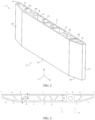
- FIG. 2 is a schematic view of a structure of an end plate shown in FIG. 1
- FIG. 3 is a top view of the structure of the end plate shown in FIG. 2 .
- the battery module includes a plurality of batteries 4 stacked in a length direction L of the battery module, and end plates 1 disposed at ends of the plurality of batteries 4 in the length direction L. Two end plates 1 are provided and disposed opposite to each other in the length direction L. Moreover, the battery module further includes two side plates 2 disposed opposite to each other in a width direction W. An insulation component 3 is arranged between an end plate 1 and a battery 4 adjacent to the end plate 1. The insulation component 3 has good thermal insulation properties and insulation properties, and thus can serve as an insulation structure and a thermal insulation structure between the end plate 1 and the battery 4 adjacent to the end plate 1. After the end plate 1 and the side plate 2 are fixed together by laser welding, the insulation component 3 and the battery 4 can be clamped to form the battery module shown in FIG. 1 .
- the end plate 1 of the battery module is provided with an end plate mounting hole (e.g., including a first end plate mounting hole 181 and a second end plate mounting hole 191 shown in FIG. 2 and FIG. 3 ), and a mounting bolt (not shown) is inserted into the end plate mounting hole to achieve assembly of the battery module.
- an end plate mounting hole e.g., including a first end plate mounting hole 181 and a second end plate mounting hole 191 shown in FIG. 2 and FIG. 3
- a mounting bolt (not shown) is inserted into the end plate mounting hole to achieve assembly of the battery module.
- the end plate 1 has the low strength and rigidity at a position of the end plate mounting hole. After the assembly is completed, the end plate 1 is subjected to an outward expansion force from the battery 4, and an inner end surface of the end plate 1 is subjected to the maximum expansion force of the battery. Therefore, the inner end surface of the end plate 1 has a risk of breaking at the position of the end plate mounting hole, thereby resulting in the low strength of the end plate. Moreover, when the inner end surface of the end plate 1 deforms outward under the expansion force of the battery, the inner end surface will press the mounting bolt disposed in the end plate mounting hole, resulting in a decrease in the mounting stability and reliability of the battery module. For solving this technical problem, an embodiment of present disclosure improves a structure of the end plate 1 so as to increase the strength of the end plate 1.
- the end plate mounting hole extends along a height direction H of the battery module, and the end plate 1 includes an inner wall 11 and an external wall 12 that are oppositely disposed along the length direction L of the battery module.
- the mounting hole is arranged between the inner wall 11 and the external wall 12, and an axis of the end plate mounting hole has a first distance L1 from the inner wall 11, and a second distance L2 from the external wall 12.
- the distance L1 is greater than the second distance L2.
- the first distance L1 is greater than the distance L2, that is, a distance between the first end plate mounting hole 181 (or the second end plate mounting hole 191) and the inner wall 11 is greater than a distance between the first end plate mounting hole 181 (or the second end plate mounting hole 191) and the external wall. Therefore, if the end plate 11 has a greater thickness at the position of the first end plate mounting hole 181 (or the second end plate mounting hole 191), the risk of the inner wall 11 breaking under the expansion force of the battery can be reduced, so that the strength of the end plate 1 can be increased.
- the structure of the end plate 1 in this invention can also reduce a risk that the external wall 11 deforms outward under the expansion force of the battery, thereby reducing pressing of the mounting bolt caused by the deformation of the inner wall 11 and thus improving the assembly reliability and stability of the battery module.
- the end plate 1 further includes a first mounting portion 18 and a second mounting portion 19 that are spaced apart in the width direction W of the battery module.
- the first mounting portion 18 is fixed to the inner wall 11 and the external wall 12
- the second mounting portion 19 is fixed to the inner wall 11 and the external wall 12. That is, each of the first mounting portion 18 and the second mounting portion 19 is a solid structure connected between the inner wall 11 and the external wall 12. Therefore, the first end plate mounting hole 181 is arranged in the first mounting portion 18, and the second end plate mounting hole 191 is arranged in the second mounting portion 19.
- the end plate 1 is provided with two end plate mounting holes, thereby achieving assembly of the battery module. Moreover, arranging the two end plate mounting holes in the mounting portions having solid structures can improve the strength and rigidity of the inner wall 11 and the external wall 12.
- each of the first mounting portion 18 and the second mounting portion 19 is formed in a square structure, each of the two mounting portions has a dimension in each direction that is greater than a dimension of the end plate mounting hole in this direction, so that the two mounting portions still have a sufficient thickness to withstand force in every direction even though the end plate mounting holes are arranged in the two mounting portions.
- the external wall 12 includes a straight wall 121, a first oblique wall 122, and a second oblique wall 123 along the width direction W of the battery module, and the first oblique wall 122 and the second oblique wall 123 are located at two ends of the straight wall 121 in the width direction W.
- the straight wall 121 is in parallel with the inner wall 11, and both the first oblique wall 122 and the second oblique wall 123 are oblique towards the inner wall 11, that is, the first oblique wall 122 and the second oblique wall 123 are oblique towards the battery 4 along the length direction L of the battery module.
- the end plate 1 includes a middle portion and two end portions.
- the inner wall 11 and the straight wall 121 at the middle portion are parallel with each other, and the middle portion of the end plate 1 has the same thicknesses in respective positions.
- Both the first oblique wall 122 and the second oblique wall 123 are oblique towards the inner wall 11, and thus the thickness of each end portion of the end plate 1 is gradually decreased.
- the thickness refers to a dimension of the end plate 1 in the length direction L.
- the energy density refers to energy stored in per unit weight of a battery. Therefore, in order to increase the energy density of the battery module, a weight of the battery module needs to be reduced.
- the middle portion is subjected to a larger expansion force, and the end portions are subjected to the smaller expansion force. That is, a requirement for the strength of the end portions is lower than that of the middle portion. Therefore, in this embodiment, reducing the thickness of the two end portions of the end plate 1 can reduce an amount of material used for the end plate 1 while satisfying the strength requirement, thereby reducing the weight of the end plate 1 and thus increasing the energy density of the battery module.
- an obtuse angle formed between the first oblique wall 122 and the straight wall 121 has a value within a range of 145°-175°, for example, 163°; and an obtuse angle formed between the second oblique wall 123 and the straight wall 121 has a value within a range of 145°-175°, for example, 163°.
- the above-mentioned two obtuse angles may have same or different values, there is no strict relationship between the two obtuse angles, and specific values of the two abuse angles may be set according to actual requirements.
- the end plate 1 further includes a first side wall 13 and a second side wall 14 at two ends in the width direction W, and both the first side wall 13 and the second side wall 14 are perpendicular to the inner wall 11.
- the first side wall 13 is connected to the first oblique wall 122 and the inner wall 11
- the second side wall 14 is connected to the second oblique wall 123 and the inner wall 11. Therefore, along the length direction L of the battery module, a length of the first side wall 13 is smaller than a distance D2 between the straight wall 121 and the inner wall 11, and a length of the second side wall 14 is smaller than the distance D2 between the straight wall 121 and the inner wall 11.
- the first side wall 13 abuts against and is welded to a corresponding side plate 2
- the second side wall 14 abuts against and is welded to a corresponding side plate 2.
- the external wall 12 since the external wall 12 includes the first oblique wall 122 and the second oblique wall 123, the first oblique wall 122 may be directly connected to the inner wall 11 after being oblique, and the second oblique wall 123 may be directly connected to the inner wall 11 after be oblique.
- the end plate 1 does not include the first side wall 13 and the second side wall 14.
- the present embodiment by providing the first side wall 13 and the second side wall 14 can increase a welding area between the end plate 1 and the side plate 2, thereby improving reliability of a connection between the end plate 1 and the side plate 2.
- the first side wall 13 forms an obtuse angle with respect to the first oblique wall 122, and forms a right angle (or approximately a right angle) with respect to the internal wall 11, which, compared with the acute angle, can reduce the stress concentration at the edge of the end plate 1.
- first mounting portion 18 two ends of the first mounting portion 18 are fixed to the straight wall 121 and the inner wall 11, respectively, and two ends of the second mounting portion 19 are fixed to the straight wall 121 and to the inner wall.
- first side wall 13, the first oblique wall 122, the inner wall 11, the first mounting portion 18, and a part of the straight wall 121 form a first cavity 15; and likewise, the second side wall 14, the second oblique wall 123, the inner wall 11, the second mounting portion 19, and a part of the straight wall 121 form a second cavity 16.
- the first cavity 15 has a width A in the width direction W
- the second cavity 16 has a width A in the width direction W.
- the width A is within a range of 25mm to 45mm, for example, 34.95 mm, 40 mm or the like.
- the cavity structures of the first cavity 15 and the second cavity 16 can reduce the weight of the end plate 1, thereby increasing the energy density of the battery module.
- the width of the first cavity 15 in the width direction W refers to a distance between the first side wall 13 and the first mounting portion 18, and the width of the second cavity 16 in the width direction W refers to a distance between the second side wall 14 and the second mounting portion 19.
- the width A of the first cavity 15 and the second cavity 16 can indicate a distance between the first end plate mounting hole 181 and the corresponding end portion of the end plate 1 and a distance between the second end plate mounting hole 191 and the corresponding end portion of the end plate 1.
- the width A being too large or too small may affect the assembly reliability of the battery module.
- the width A is too large, the first end plate mounting hole 181 and the second end plate mounting hole 191 will be close to the middle portion of the end plate 1 which is subjected to a large expansion force of the battery, thereby reducing the strength of the end plate 1 and the resistance against the expansion force of the battery, and as a result, deformation and failure may easily occur.
- the width A is too small, the first oblique wall 122 and the second oblique wall 123 will be small and the end plate 1 will have a large weight, which is not conducive to increasing the energy density of the battery module. Therefore, in this embodiment, all of the assembly reliability of the battery module, the strength of the end plate 1 and the energy density of the battery module should be considered, and then the width A of the cavity can be reasonably set.
- a first strengthening rib 151 is provided in the first cavity 15, and a second strengthening rib 161 is provided in the second cavity 16.
- the first strengthening rib 151 and the second strengthening rib 161 are obliquely disposed and oblique towards opposite directions. Two ends of the first strengthening rib 151 are respectively fixed to the inner wall 11 and the straight wall 121, and two ends of the second strengthening rib 161 are respectively fixed to the inner wall 11 and the straight wall 121.
- the first strengthening rib 151 divides the first cavity 15 into two cavities having different shapes, one being in a pentagonal structure and the other being in a quadrangular structure, and a truss structure formed by the two can further increase the strength of the end plate 1.
- providing the first strengthening rib 151 in the first cavity 15 and the second strengthening rib 161 in the second cavity 16 can improve the strength of the end plate 1 in the first cavity 15 and the second cavity 16.
- the first strengthening rib151 and the second strengthening rib 161 being oblique can reduce the number of ribs while improving the strength, thereby reducing the weight of the end plate 1.
- the obtuse angle formed between the first strengthening rib 151 and the straight wall 121 is within a range of 100° to 150°, for example, 120°, 126.8° or the like; and likewise, the obtuse angle formed between the second strengthening rib161 and the straight wall 121 is within a range of 100° to 150°, for example, 126.8°, 130° or the like.
- the above-mentioned two obtuse angles may have a same value or different values, and either one of the two obtuse angles may have a larger value than that of the other one, and the specific values of the two abuse angles may be set according to actual requirements.
- the first mounting portion 18, the second mounting portion 19, the inner wall 11, and the straight wall 121 form a third cavity 17, and the third cavity 17 has a rectangular cross section.
- a plurality of third strengthening ribs 171 are provided in the third cavity 17, and two ends of each third strengthening rib 171 are fixed to the inner wall 11 and the straight wall 121, respectively.
- providing the third strengthening ribs 171 in the third cavity 17 can improve the strength of the end plate 1 at a position of the third cavity 17.
- the end plate 1 is subjected to a large expansion force of the battery at the position of the third cavity 17, and therefore, in order to make it have sufficient strength, a plurality of third strengthening ribs 171 are provided in the third cavity 17.
- each of a thickness of the first strengthening rib 151, a thickness of the second strengthening rib 161, and a thickness of the third strengthening rib 171 is smaller than or equal to each of a thickness of the inner wall 11 and a thickness of the external wall 12.
- the thicknesses of the three strengthening ribs should not be too large.
- the thicknesses of the three strengthening ribs may be smaller than or equal to the thickness of the inner wall 11 and the thickness of the external wall 12. In this case, the strength of the end plate 1 can be improved, and the end plate 1 can be prevented from being excessively heavy due to the addition of the reinforcing ribs.
- both the first mounting portion 18 and the second mounting portion 19 are in prismatic structures, and the first mounting portion 18 and the second mounting portion 19 are disposed symmetrically with respect to a center line of the end plate (e.g., length direction L of the battery module).
- each of the third strengthening ribs 171 is oblique, and adjacent third strengthening ribs 171 have opposite oblique directions, thereby improving uniformity in strength of respective portions of the end plate 1 and reducing the number of third strengthening ribs 171.
- adjacent third strengthening ribs 171 form a triangular structure with the inner wall 11 or with the straight wall 121; or, a third strengthening rib 171, the inner wall 11, the straight wall 121 and the corresponding mounting portion form a trapezoidal structure.
- the first mounting portion 18 and the second mounting portion 19 each have a rectangular structure, and therefore, when there are oblique third strengthening ribs 171 provided in the third cavity 17, each of two third strengthening ribs 171 located at two edges of the third cavity 17 in the width direction W can form a trapezoidal structure with the corresponding mounting portion, the corresponding inner wall 11 and the corresponding external wall 12, and a top edge of the trapezoid (the shorter side) is formed by the inner wall 11. Therefore, the inner wall 11 and the external wall 12 are supported by the first mounting portion 18 (or second mounting portion 19) and the third strengthening ribs 171, and a distance between supporting points on the inner wall 11 is smaller than a distance between supporting points on the external wall 12.
- an improvement in the strength of the inner wall 11 is more than an improvement in the strength of the external wall 12. That is, the strength of the inner wall 11 is larger than the strength of the external wall 12, thereby further reducing the risk of the inner wall 11 of the end plate 1 breaking under the expansion force of the battery.
- the trapezoidal structure can reduce the number of third strengthening ribs 171 and the weight of the end plate 1 while improving the strength of the end plate 1.
- a sum of the thickness of the inner wall 11 of the end plate 1 and the thickness of the external wall 12 of the end plate 1 is D1
- a distance between the inner wall 11 and the external wall 12 is D2.
- a ratio of D1 to D2 is within a range of 1/5 to 3/5.
- the thickness of the inner wall 11 of the end plate 1 is 1.8mm, and the thickness of the external wall 12 is 2.2mm. Then, a sum of the thickness of the inner wall 11 and the thickness of the external wall 12 is 4mm. The distance between the inner wall 11 and the external wall 12 is 10.2mm, and then the ratio of D1 to D2 in this embodiment is approximately equal to 0.4.
- the ratio of D1 to D2 is, the larger the strength and weight of the end plate 1 are; and the smaller the ratio of D1 to D2 is, the smaller the strength and weight of the end plate 1 are. Therefore, the ratio of D1 to D2 can be reasonably set in consideration of the strength and weight of the end plate 1.
- the end plate mounting hole is a circular hole, a kidney-shaped hole or an elliptical hole.
- the end plate mounting hole and a battery pack mounting hole should be arranged coaxially.
- the end plate mounting hole can be a kidney-shaped hole or an elliptical hole.
- the kidney-shaped hole or elliptical hole can allow the assembly to be performed even if the end plate mounting hole and the battery pack mounting hole are arranged at a low coaxiality.
- the end plate mounting hole is a kidney-shaped hole or an elliptical hole, preferably, having a long edge along the width direction W of the battery module and a short edge along the length direction L of the battery module, it can be achieved that the end plate 1 has sufficient strength along the length direction L.
- the end plate 1 can not only withstand the expansion force of the battery, but also have a small weight while increasing the energy density of the battery module.
Landscapes
- Chemical & Material Sciences (AREA)
- Chemical Kinetics & Catalysis (AREA)
- Electrochemistry (AREA)
- General Chemical & Material Sciences (AREA)
- Battery Mounting, Suspending (AREA)
Claims (6)
- Batteriemodul, dadurch gekennzeichnet, dass es Folgendes umfasst:eine Vielzahl von Batterien (4), die in einer Längsrichtung L des Batteriemoduls gestapelt sind; und eine Endplatte (1), die sich an einem Ende der Vielzahl von Batterien (4) in der Längsrichtung L befindet,wobei die Endplatte (1) mit mindestens einem Endplattenmontageloch (181, 191) versehen ist, und jedes des mindestens einen Endplattenmontagelochs (181, 191) sich entlang einer Höhenrichtung H des Batteriemoduls erstreckt,die Endplatte (1) eine Innenwand (11) und eine Außenwand (12) umfasst, die in der Längsrichtung L einander gegenüberliegend angeordnet sind, und eine Achse jedes des mindestens einen Endplattenmontagelochs (181, 191) eine erste Entfernung L1 von der Innenwand (11) und eine zweite Entfernung L2 von der Außenwand (12) umfasst, unddie erste Entfernung L1 größer ist als die zweite Entfernung L2,wobei die Endplatte (1) ferner einen ersten Montageabschnitt (18) und einen zweiten Montageabschnitt (19) umfasst, die entlang einer Breitenrichtung W des Batteriemoduls voneinander beabstandet sind;der erste Montageabschnitt (18) an der Innenwand (11) und der Außenwand (12) fixiert ist, und der zweite Montageabschnitt (19) an der Innenwand (11) und der Außenwand (12) fixiert ist, undsowohl der erste Montageabschnitt (18) als auch der zweite Montageabschnitt (19) mit einem des mindestens einen Endplattenmontagelochs (181, 191) versehen ist, wobei die Außenwand (12) eine gerade Wand (121), eine erste schräge Wand (122) und eine zweite schräge Wand (123) umfasst, und die erste schräge Wand (122) und die zweite schräge Wand (123) sich an zwei Enden der geraden Wand (121) entlang der Breitenrichtung W befinden,die gerade Wand (121) parallel zu der Innenwand (11) ist und sowohl die erste schräge Wand (122) als auch die zweite schräge Wand (123) schräg zu der Innenwand (11) sind, undein stumpfer Winkel, der zwischen der ersten schrägen Wand (122) und der geraden Wand (121) gebildet wird, innerhalb eines Bereichs von 145° bis 175° liegt, und ein stumpfer Winkel, der zwischen der zweiten schrägen Wand (123) und der geraden Wand (121) gebildet wird, innerhalb eines Bereichs von 145° bis 175° liegt,wobei die Endplatte (1) ferner eine erste Seitenwand (13) und eine zweite Seitenwand (14) an zwei Enden in der Breitenrichtung W umfasst;entlang der Längsrichtung L des Batteriemoduls eine Länge der ersten Seitenwand (13) kleiner ist als eine Entfernung D2 zwischen der geraden Wand (121) und der Innenwand (11), und eine Länge der zweiten Seitenwand (14) kleiner ist als die Entfernung D2 zwischen der geraden Wand (121) und der Innenwand (11),wobei der erste Montageabschnitt (18) an der geraden Wand (121) und der Innenwand (11) fixiert ist, und der zweite Montageabschnitt (19) an der geraden Wand (121) und der Innenwand (11) fixiert ist,ein erster Hohlraum (15) durch die erste Seitenwand (13), die erste schräge Wand (122), die Innenwand (11), den ersten Montageabschnitt (18) und einen Teil der geraden Wand (121) definiert ist,ein zweiter Hohlraum (16) durch die zweite Seitenwand (14), die zweite schräge Wand (123), die Innenwand (11), den zweiten Montageabschnitt (19) und einen weiteren Teil der geraden Wand (121) definiert ist,der erste Hohlraum (15) eine Breite A entlang der Breitenrichtung W hat, und der zweite Hohlraum (16) eine Breite A entlang der Breitenrichtung W hat, und wobei die Breite A in einem Bereich von 25 mm bis 45 mm liegt.
- Batteriemodul nach Anspruch 1, dadurch gekennzeichnet, dass eine erste Verstärkungsrippe (151) in dem ersten Hohlraum (15) und eine zweite Verstärkungsrippe (161) in dem zweiten Hohlraum (16) bereitgestellt ist,die erste Verstärkungsrippe (151) und die zweite Verstärkungsrippe (161) schräg und in verschiedene Richtungen angeordnet sind,die erste Verstärkungsrippe (151) zwei an der Innenwand (11) und der geraden Wand (121) fixierte Enden umfasst, und die zweite Verstärkungsrippe (161) zwei an der Innenwand (11) und der geraden Wand (121) fixierte Enden umfasst, undein stumpfer Winkel, der zwischen der ersten Verstärkungsrippe (151) und der geraden Wand (121) gebildet wird, innerhalb eines Bereichs von 100° bis 150° liegt, und ein stumpfer Winkel, der zwischen der zweiten Verstärkungsrippe (161) und der geraden Wand (121) gebildet wird, innerhalb eines Bereichs von 100° bis 150° liegt.
- Batteriemodul nach Anspruch 2, dadurch gekennzeichnet, dass ein dritter Hohlraum (17) durch den ersten Montageabschnitt (18), den zweiten Montageabschnitt (19), die Innenwand (11) und die gerade Wand (121) definiert ist,eine Vielzahl von dritten Verstärkungsrippen (171) in dem dritten Hohlraum (17) bereitgestellt ist, undjede der Vielzahl von dritten Verstärkungsrippen (171) zwei Enden umfasst, die an der Innenwand (11) und der geraden Wand (121) fixiert sind, undjeweils eine Dicke der ersten Verstärkungsrippe (151), eine Dicke der zweiten Verstärkungsrippe (161) und eine Dicke der dritten Verstärkungsrippe (17) kleiner oder gleich einer Dicke der Innenwand (11) und einer Dicke der Außenwand (12) ist.
- Batteriemodul nach Anspruch 3, dadurch gekennzeichnet, dass der erste Montageabschnitt (18) und der zweite Montageabschnitt (19) jeweils eine prismatische Struktur haben und der erste Montageabschnitt (18) und der zweite Montageabschnitt (19) symmetrisch in Bezug auf die Längsrichtung L des Batteriemoduls angeordnet sind,jede der Vielzahl von dritten Verstärkungsrippen (171) schräg angeordnet ist, und benachbarte dritte Verstärkungsrippen (171) der Vielzahl von dritten Verstärkungsrippen (171) in verschiedene Richtungen schräg sind, undeine Struktur, umfassend einen dreieckigen Querschnitt, durch zwei benachbarte dritte Verstärkungsrippen (171) der Vielzahl von dritten Verstärkungsrippen (171) und die Innenwand (11) oder die gerade Wand (121) gebildet wird; oder eine Struktur, umfassend einen trapezförmigen Querschnitt, durch eine der Vielzahl von dritten Verstärkungsrippen (171), die Innenwand (11), die gerade Wand (121) und einen entsprechenden Montageabschnitt des ersten Montageabschnitts (18) und des zweiten Montageabschnitts (19) gebildet wird.
- Batteriemodul nach einem der Ansprüche 1 bis 4, dadurch gekennzeichnet, dass eine Summe einer Dicke der Innenwand (11) und einer Dicke der Außenwand (12) D1 ist, eine Entfernung zwischen der Innenwand (11) und der Außenwand (12) D2 ist und ein Verhältnis von D1 zu D2 in einem Bereich von 1/5 bis 3/5 liegt.
- Batteriemodul nach einem der Ansprüche 1 bis 5, dadurch gekennzeichnet, dass jedes des mindestens einen Endplattenmontagelochs (181, 191) ein kreisförmiges Loch, ein nierenförmiges Loch oder ein elliptisches Loch ist.
Applications Claiming Priority (1)
| Application Number | Priority Date | Filing Date | Title |
|---|---|---|---|
| CN201910141026.0A CN109841774B (zh) | 2019-02-26 | 2019-02-26 | 一种电池模组 |
Publications (2)
| Publication Number | Publication Date |
|---|---|
| EP3703153A1 EP3703153A1 (de) | 2020-09-02 |
| EP3703153B1 true EP3703153B1 (de) | 2025-05-14 |
Family
ID=66885002
Family Applications (1)
| Application Number | Title | Priority Date | Filing Date |
|---|---|---|---|
| EP19191678.2A Active EP3703153B1 (de) | 2019-02-26 | 2019-08-14 | Batteriemodul |
Country Status (4)
| Country | Link |
|---|---|
| US (1) | US11742544B2 (de) |
| EP (1) | EP3703153B1 (de) |
| CN (2) | CN112086599B (de) |
| WO (1) | WO2020173383A1 (de) |
Families Citing this family (9)
| Publication number | Priority date | Publication date | Assignee | Title |
|---|---|---|---|---|
| CN112086599B (zh) * | 2019-02-26 | 2023-08-01 | 宁德时代新能源科技股份有限公司 | 一种电池模组 |
| CN113043323A (zh) * | 2021-02-05 | 2021-06-29 | 深圳众为兴技术股份有限公司 | 一种水平关节机械臂及其制造方法 |
| EP4354615A4 (de) * | 2021-11-30 | 2025-01-01 | Contemporary Amperex Technology (Hong Kong) Limited | Batteriemodul, batteriepack, elektrische vorrichtung und verfahren zur herstellung eines batteriemoduls |
| CN216389633U (zh) * | 2021-11-30 | 2022-04-26 | 宁德时代新能源科技股份有限公司 | 端板、电池模块、电池及用电设备 |
| CN115411332B (zh) * | 2022-07-20 | 2025-09-09 | 东风汽车集团股份有限公司 | 一种燃料电池电堆、燃料电池系统以及车辆 |
| CN116247360B (zh) * | 2023-03-31 | 2025-09-09 | 楚能新能源股份有限公司 | 一种长模组固定组件及电池包 |
| CN116315385B (zh) * | 2023-04-24 | 2026-01-30 | 武汉亿纬储能有限公司 | 电池模组固定端板及电池模组 |
| WO2024243929A1 (zh) * | 2023-05-31 | 2024-12-05 | 深圳海辰储能控制技术有限公司 | 储能模组及储能系统 |
| CN221352986U (zh) * | 2023-10-30 | 2024-07-16 | 惠州亿纬锂能股份有限公司 | 加强组件及电池模组 |
Family Cites Families (15)
| Publication number | Priority date | Publication date | Assignee | Title |
|---|---|---|---|---|
| JP2000138044A (ja) * | 1998-10-30 | 2000-05-16 | Kenwood Corp | バッテリケース |
| GB2501711A (en) * | 2012-05-01 | 2013-11-06 | Intelligent Energy Ltd | Fuel Cell Stack Assembly |
| DE102012211180A1 (de) * | 2012-06-28 | 2014-04-03 | Bayerische Motoren Werke Aktiengesellschaft | Energiespeichermodul aus mehreren prismatischen Speicherzellen |
| JP5954258B2 (ja) * | 2013-05-24 | 2016-07-20 | 株式会社デンソー | 電池パック及びその製造方法 |
| DE102014217220A1 (de) * | 2014-08-28 | 2016-03-03 | Bayerische Motoren Werke Aktiengesellschaft | Gehäuse für einen Brennstoffzellenstapel |
| CN205609590U (zh) * | 2016-05-05 | 2016-09-28 | 宁德时代新能源科技股份有限公司 | 电池模组 |
| CN206022482U (zh) * | 2016-09-06 | 2017-03-15 | 宁德时代新能源科技股份有限公司 | 电池模组 |
| CN106654103B (zh) * | 2017-01-20 | 2019-10-22 | 宁德时代新能源科技股份有限公司 | 电池模组端板及电池模组 |
| JP2020113361A (ja) * | 2017-05-12 | 2020-07-27 | 三洋電機株式会社 | 電源装置及びこれを備える車両、蓄電装置並びに電源装置用セパレータ |
| JP6568900B2 (ja) * | 2017-07-06 | 2019-08-28 | 本田技研工業株式会社 | バッテリモジュール |
| JP6706598B2 (ja) * | 2017-07-06 | 2020-06-10 | 本田技研工業株式会社 | バッテリモジュール |
| CN207441760U (zh) * | 2017-11-17 | 2018-06-01 | 宁德时代新能源科技股份有限公司 | 端板及电池模组 |
| CN108428834B (zh) * | 2018-04-11 | 2024-11-19 | 江苏正力新能电池技术股份有限公司 | 一种动力电池模组结构 |
| CN108899456B (zh) * | 2018-08-31 | 2024-04-23 | 常州普莱德新能源电池科技有限公司 | 一种电池模组及制造方法 |
| CN112086599B (zh) * | 2019-02-26 | 2023-08-01 | 宁德时代新能源科技股份有限公司 | 一种电池模组 |
-
2019
- 2019-02-26 CN CN202011002400.8A patent/CN112086599B/zh active Active
- 2019-02-26 CN CN201910141026.0A patent/CN109841774B/zh active Active
- 2019-08-14 EP EP19191678.2A patent/EP3703153B1/de active Active
- 2019-08-19 US US16/544,689 patent/US11742544B2/en active Active
-
2020
- 2020-02-20 WO PCT/CN2020/076056 patent/WO2020173383A1/zh not_active Ceased
Also Published As
| Publication number | Publication date |
|---|---|
| CN109841774B (zh) | 2020-10-27 |
| CN109841774A (zh) | 2019-06-04 |
| EP3703153A1 (de) | 2020-09-02 |
| US20200274115A1 (en) | 2020-08-27 |
| CN112086599B (zh) | 2023-08-01 |
| CN112086599A (zh) | 2020-12-15 |
| US11742544B2 (en) | 2023-08-29 |
| WO2020173383A1 (zh) | 2020-09-03 |
Similar Documents
| Publication | Publication Date | Title |
|---|---|---|
| EP3703153B1 (de) | Batteriemodul | |
| US11329347B2 (en) | Battery pack and vehicle | |
| CN109742281B (zh) | 一种电池箱 | |
| EP3270439B1 (de) | Batteriemodul | |
| EP4148874B1 (de) | Batteriekasten | |
| EP3506391B1 (de) | Batteriemodul mit verbundendplatte | |
| KR20250164867A (ko) | 배터리 팩 및 전기 자동차 | |
| EP3726611B1 (de) | Batteriemodul und batteriepack | |
| KR20180018109A (ko) | 프레임의 구조가 개선된 배터리 모듈 및 이를 위한 프레임 어셈블리 | |
| WO2019128640A1 (zh) | 复合端板以及电池模组 | |
| EP3579299B1 (de) | Batteriemodul | |
| EP3706192B1 (de) | Batteriemodul und batteriepack | |
| EP2490278B1 (de) | Zellenabstandhalter für einen Batteriemodul | |
| EP3790073B1 (de) | Batteriepack | |
| JP2019075276A (ja) | 組電池 | |
| CN213026344U (zh) | 托盘、电池包及电动汽车 | |
| CN209447950U (zh) | 一种电池模组 | |
| CN222463330U (zh) | 一种电连接片、电池包以及用电设备 | |
| JP2011113706A (ja) | 電池モジュール | |
| CN220189848U (zh) | 一种电池转接片及锂离子电池 | |
| CN216213798U (zh) | 电池箱体及电池包 | |
| CN212571195U (zh) | 电芯组固定结构 | |
| KR102920660B1 (ko) | 배터리 모듈 및 그 조립 방법 | |
| KR102876793B1 (ko) | 배터리 팩 | |
| CN222530533U (zh) | 电池装置 |
Legal Events
| Date | Code | Title | Description |
|---|---|---|---|
| PUAI | Public reference made under article 153(3) epc to a published international application that has entered the european phase |
Free format text: ORIGINAL CODE: 0009012 |
|
| STAA | Information on the status of an ep patent application or granted ep patent |
Free format text: STATUS: REQUEST FOR EXAMINATION WAS MADE |
|
| 17P | Request for examination filed |
Effective date: 20190904 |
|
| AK | Designated contracting states |
Kind code of ref document: A1 Designated state(s): AL AT BE BG CH CY CZ DE DK EE ES FI FR GB GR HR HU IE IS IT LI LT LU LV MC MK MT NL NO PL PT RO RS SE SI SK SM TR |
|
| AX | Request for extension of the european patent |
Extension state: BA ME |
|
| RBV | Designated contracting states (corrected) |
Designated state(s): AL AT BE BG CH CY CZ DE DK EE ES FI FR GB GR HR HU IE IS IT LI LT LU LV MC MK MT NL NO PL PT RO RS SE SI SK SM TR |
|
| STAA | Information on the status of an ep patent application or granted ep patent |
Free format text: STATUS: EXAMINATION IS IN PROGRESS |
|
| 17Q | First examination report despatched |
Effective date: 20210209 |
|
| RAP1 | Party data changed (applicant data changed or rights of an application transferred) |
Owner name: CONTEMPORARY AMPEREX TECHNOLOGY(HONG KONG) LIMITED |
|
| REG | Reference to a national code |
Ref country code: DE Ref legal event code: R079 Free format text: PREVIOUS MAIN CLASS: H01M0002100000 Ipc: H01M0050209000 Ref country code: DE Ref legal event code: R079 Ref document number: 602019069887 Country of ref document: DE Free format text: PREVIOUS MAIN CLASS: H01M0002100000 Ipc: H01M0050209000 |
|
| GRAP | Despatch of communication of intention to grant a patent |
Free format text: ORIGINAL CODE: EPIDOSNIGR1 |
|
| STAA | Information on the status of an ep patent application or granted ep patent |
Free format text: STATUS: GRANT OF PATENT IS INTENDED |
|
| GRAS | Grant fee paid |
Free format text: ORIGINAL CODE: EPIDOSNIGR3 |
|
| RIC1 | Information provided on ipc code assigned before grant |
Ipc: H01M 50/209 20210101AFI20250303BHEP |
|
| GRAA | (expected) grant |
Free format text: ORIGINAL CODE: 0009210 |
|
| STAA | Information on the status of an ep patent application or granted ep patent |
Free format text: STATUS: THE PATENT HAS BEEN GRANTED |
|
| INTG | Intention to grant announced |
Effective date: 20250313 |
|
| AK | Designated contracting states |
Kind code of ref document: B1 Designated state(s): AL AT BE BG CH CY CZ DE DK EE ES FI FR GB GR HR HU IE IS IT LI LT LU LV MC MK MT NL NO PL PT RO RS SE SI SK SM TR |
|
| REG | Reference to a national code |
Ref country code: GB Ref legal event code: FG4D |
|
| REG | Reference to a national code |
Ref country code: CH Ref legal event code: EP |
|
| P01 | Opt-out of the competence of the unified patent court (upc) registered |
Free format text: CASE NUMBER: APP_19276/2025 Effective date: 20250422 |
|
| REG | Reference to a national code |
Ref country code: IE Ref legal event code: FG4D |
|
| REG | Reference to a national code |
Ref country code: DE Ref legal event code: R096 Ref document number: 602019069887 Country of ref document: DE |
|
| REG | Reference to a national code |
Ref country code: NL Ref legal event code: MP Effective date: 20250514 |
|
| PG25 | Lapsed in a contracting state [announced via postgrant information from national office to epo] |
Ref country code: FI Free format text: LAPSE BECAUSE OF FAILURE TO SUBMIT A TRANSLATION OF THE DESCRIPTION OR TO PAY THE FEE WITHIN THE PRESCRIBED TIME-LIMIT Effective date: 20250514 Ref country code: PT Free format text: LAPSE BECAUSE OF FAILURE TO SUBMIT A TRANSLATION OF THE DESCRIPTION OR TO PAY THE FEE WITHIN THE PRESCRIBED TIME-LIMIT Effective date: 20250915 Ref country code: ES Free format text: LAPSE BECAUSE OF FAILURE TO SUBMIT A TRANSLATION OF THE DESCRIPTION OR TO PAY THE FEE WITHIN THE PRESCRIBED TIME-LIMIT Effective date: 20250514 |
|
| PGFP | Annual fee paid to national office [announced via postgrant information from national office to epo] |
Ref country code: DE Payment date: 20250827 Year of fee payment: 7 |
|
| REG | Reference to a national code |
Ref country code: LT Ref legal event code: MG9D |
|
| PG25 | Lapsed in a contracting state [announced via postgrant information from national office to epo] |
Ref country code: NO Free format text: LAPSE BECAUSE OF FAILURE TO SUBMIT A TRANSLATION OF THE DESCRIPTION OR TO PAY THE FEE WITHIN THE PRESCRIBED TIME-LIMIT Effective date: 20250814 Ref country code: GR Free format text: LAPSE BECAUSE OF FAILURE TO SUBMIT A TRANSLATION OF THE DESCRIPTION OR TO PAY THE FEE WITHIN THE PRESCRIBED TIME-LIMIT Effective date: 20250815 |
|
| PG25 | Lapsed in a contracting state [announced via postgrant information from national office to epo] |
Ref country code: NL Free format text: LAPSE BECAUSE OF FAILURE TO SUBMIT A TRANSLATION OF THE DESCRIPTION OR TO PAY THE FEE WITHIN THE PRESCRIBED TIME-LIMIT Effective date: 20250514 Ref country code: PL Free format text: LAPSE BECAUSE OF FAILURE TO SUBMIT A TRANSLATION OF THE DESCRIPTION OR TO PAY THE FEE WITHIN THE PRESCRIBED TIME-LIMIT Effective date: 20250514 |
|
| REG | Reference to a national code |
Ref country code: AT Ref legal event code: MK05 Ref document number: 1795620 Country of ref document: AT Kind code of ref document: T Effective date: 20250514 |
|
| PG25 | Lapsed in a contracting state [announced via postgrant information from national office to epo] |
Ref country code: BG Free format text: LAPSE BECAUSE OF FAILURE TO SUBMIT A TRANSLATION OF THE DESCRIPTION OR TO PAY THE FEE WITHIN THE PRESCRIBED TIME-LIMIT Effective date: 20250514 |
|
| PGFP | Annual fee paid to national office [announced via postgrant information from national office to epo] |
Ref country code: GB Payment date: 20250826 Year of fee payment: 7 |
|
| PG25 | Lapsed in a contracting state [announced via postgrant information from national office to epo] |
Ref country code: HR Free format text: LAPSE BECAUSE OF FAILURE TO SUBMIT A TRANSLATION OF THE DESCRIPTION OR TO PAY THE FEE WITHIN THE PRESCRIBED TIME-LIMIT Effective date: 20250514 |
|
| PG25 | Lapsed in a contracting state [announced via postgrant information from national office to epo] |
Ref country code: AT Free format text: LAPSE BECAUSE OF FAILURE TO SUBMIT A TRANSLATION OF THE DESCRIPTION OR TO PAY THE FEE WITHIN THE PRESCRIBED TIME-LIMIT Effective date: 20250514 |
|
| PGFP | Annual fee paid to national office [announced via postgrant information from national office to epo] |
Ref country code: FR Payment date: 20250826 Year of fee payment: 7 |
|
| PG25 | Lapsed in a contracting state [announced via postgrant information from national office to epo] |
Ref country code: RS Free format text: LAPSE BECAUSE OF FAILURE TO SUBMIT A TRANSLATION OF THE DESCRIPTION OR TO PAY THE FEE WITHIN THE PRESCRIBED TIME-LIMIT Effective date: 20250814 |
|
| PG25 | Lapsed in a contracting state [announced via postgrant information from national office to epo] |
Ref country code: IS Free format text: LAPSE BECAUSE OF FAILURE TO SUBMIT A TRANSLATION OF THE DESCRIPTION OR TO PAY THE FEE WITHIN THE PRESCRIBED TIME-LIMIT Effective date: 20250914 |
|
| PG25 | Lapsed in a contracting state [announced via postgrant information from national office to epo] |
Ref country code: LV Free format text: LAPSE BECAUSE OF FAILURE TO SUBMIT A TRANSLATION OF THE DESCRIPTION OR TO PAY THE FEE WITHIN THE PRESCRIBED TIME-LIMIT Effective date: 20250514 |
|
| PG25 | Lapsed in a contracting state [announced via postgrant information from national office to epo] |
Ref country code: SM Free format text: LAPSE BECAUSE OF FAILURE TO SUBMIT A TRANSLATION OF THE DESCRIPTION OR TO PAY THE FEE WITHIN THE PRESCRIBED TIME-LIMIT Effective date: 20250514 Ref country code: DK Free format text: LAPSE BECAUSE OF FAILURE TO SUBMIT A TRANSLATION OF THE DESCRIPTION OR TO PAY THE FEE WITHIN THE PRESCRIBED TIME-LIMIT Effective date: 20250514 |
|
| PG25 | Lapsed in a contracting state [announced via postgrant information from national office to epo] |
Ref country code: CZ Free format text: LAPSE BECAUSE OF FAILURE TO SUBMIT A TRANSLATION OF THE DESCRIPTION OR TO PAY THE FEE WITHIN THE PRESCRIBED TIME-LIMIT Effective date: 20250514 |
|
| PG25 | Lapsed in a contracting state [announced via postgrant information from national office to epo] |
Ref country code: EE Free format text: LAPSE BECAUSE OF FAILURE TO SUBMIT A TRANSLATION OF THE DESCRIPTION OR TO PAY THE FEE WITHIN THE PRESCRIBED TIME-LIMIT Effective date: 20250514 |
|
| PG25 | Lapsed in a contracting state [announced via postgrant information from national office to epo] |
Ref country code: SK Free format text: LAPSE BECAUSE OF FAILURE TO SUBMIT A TRANSLATION OF THE DESCRIPTION OR TO PAY THE FEE WITHIN THE PRESCRIBED TIME-LIMIT Effective date: 20250514 Ref country code: RO Free format text: LAPSE BECAUSE OF FAILURE TO SUBMIT A TRANSLATION OF THE DESCRIPTION OR TO PAY THE FEE WITHIN THE PRESCRIBED TIME-LIMIT Effective date: 20250514 |
|
| PG25 | Lapsed in a contracting state [announced via postgrant information from national office to epo] |
Ref country code: IT Free format text: LAPSE BECAUSE OF FAILURE TO SUBMIT A TRANSLATION OF THE DESCRIPTION OR TO PAY THE FEE WITHIN THE PRESCRIBED TIME-LIMIT Effective date: 20250514 |
|
| REG | Reference to a national code |
Ref country code: DE Ref legal event code: R097 Ref document number: 602019069887 Country of ref document: DE |
|
| PLBE | No opposition filed within time limit |
Free format text: ORIGINAL CODE: 0009261 |
|
| STAA | Information on the status of an ep patent application or granted ep patent |
Free format text: STATUS: NO OPPOSITION FILED WITHIN TIME LIMIT |
|
| REG | Reference to a national code |
Ref country code: CH Ref legal event code: H13 Free format text: ST27 STATUS EVENT CODE: U-0-0-H10-H13 (AS PROVIDED BY THE NATIONAL OFFICE) Effective date: 20260324 |
|
| REG | Reference to a national code |
Ref country code: CH Ref legal event code: L10 Free format text: ST27 STATUS EVENT CODE: U-0-0-L10-L00 (AS PROVIDED BY THE NATIONAL OFFICE) Effective date: 20260325 |
|
| PG25 | Lapsed in a contracting state [announced via postgrant information from national office to epo] |
Ref country code: MC Free format text: LAPSE BECAUSE OF FAILURE TO SUBMIT A TRANSLATION OF THE DESCRIPTION OR TO PAY THE FEE WITHIN THE PRESCRIBED TIME-LIMIT Effective date: 20250514 |
|
| PG25 | Lapsed in a contracting state [announced via postgrant information from national office to epo] |
Ref country code: LU Free format text: LAPSE BECAUSE OF NON-PAYMENT OF DUE FEES Effective date: 20250814 |
|
| 26N | No opposition filed |
Effective date: 20260217 |
|
| PG25 | Lapsed in a contracting state [announced via postgrant information from national office to epo] |
Ref country code: CH Free format text: LAPSE BECAUSE OF NON-PAYMENT OF DUE FEES Effective date: 20250831 |