EP3702173B1 - Nachlaufmodul und roboter - Google Patents
Nachlaufmodul und roboter Download PDFInfo
- Publication number
- EP3702173B1 EP3702173B1 EP20159686.3A EP20159686A EP3702173B1 EP 3702173 B1 EP3702173 B1 EP 3702173B1 EP 20159686 A EP20159686 A EP 20159686A EP 3702173 B1 EP3702173 B1 EP 3702173B1
- Authority
- EP
- European Patent Office
- Prior art keywords
- omni wheel
- bearing
- effector
- groove
- shaft
- Prior art date
- Legal status (The legal status is an assumption and is not a legal conclusion. Google has not performed a legal analysis and makes no representation as to the accuracy of the status listed.)
- Active
Links
Images




Classifications
-
- B—PERFORMING OPERATIONS; TRANSPORTING
- B60—VEHICLES IN GENERAL
- B60B—VEHICLE WHEELS; CASTORS; AXLES FOR WHEELS OR CASTORS; INCREASING WHEEL ADHESION
- B60B19/00—Wheels not otherwise provided for or having characteristics specified in one of the subgroups of this group
- B60B19/003—Multidirectional wheels
-
- B—PERFORMING OPERATIONS; TRANSPORTING
- B25—HAND TOOLS; PORTABLE POWER-DRIVEN TOOLS; MANIPULATORS
- B25J—MANIPULATORS; CHAMBERS PROVIDED WITH MANIPULATION DEVICES
- B25J5/00—Manipulators mounted on wheels or on carriages
- B25J5/007—Manipulators mounted on wheels or on carriages mounted on wheels
-
- B—PERFORMING OPERATIONS; TRANSPORTING
- B25—HAND TOOLS; PORTABLE POWER-DRIVEN TOOLS; MANIPULATORS
- B25J—MANIPULATORS; CHAMBERS PROVIDED WITH MANIPULATION DEVICES
- B25J9/00—Program-controlled manipulators
- B25J9/10—Program-controlled manipulators characterised by positioning means for manipulator elements
- B25J9/108—Bearings specially adapted therefor
Definitions
- the present invention relates to the technical field of robots, and in particular, relate to a caster module and a robot.
- An omni wheel is a wheel implementing omni-directional movements.
- a movement platform built by using the omni wheels by controlling rotation of the omni wheels, advance, retract or steering of the movement platform may be implemented.
- a caster module of a robot employs omni wheels as rolling wheels, the robot may move towards different directions by rotation of the omni wheels.
- the inventors have identified that: at present, in the caster module of the robot, an omni wheel and an effector are separately disposed, and the omni wheel is connected to the effector by a rotation shaft.
- the caster module occupies a larger space, the integration degree is low, and thus the robot may be heavier.
- US2018/361784A1 discloses a running wheel for a patient positioning device 30.
- the running wheel has a wheel 1 and a receiving device 4 for rotatably receiving the wheel 1 around a first rotational axis 5, which is arranged centrally with respect to a circumference of the wheel 1.
- the wheel 1 has a wheel body 3, and multiple circumferential castors 7, each having a second rotational axis 8 arranged in a direction tangential to a circumference of the wheel 1, wherein the circumferential castors 7 form a bearing surface of the wheel 1.
- the present invention intended to provide a caster module and a robot, to reduce spaced occupied by the caster, such that integration degree is higher and the robot becomes lighter.
- the caster module includes an omni wheel, provided with an shaft groove; and an effector, received in the shaft groove, wherein a case of the effector is rotatable relative to an inner wall of the shaft groove, and an output end of the effector is connected to the omni wheel and configured to drive the omni wheel to rotate,
- the omni wheel includes an inner-side hub, an omni wheel primary structure, an outer-side hub, an inner-side roller, and an outer-side roller; wherein the shaft groove is disposed on the omni wheel primary structure, the inner-side hub and the outer-side hub are both connected to the omni wheel primary structure, the inner-side hub and the outer-side hub are respectively disposed at two ends of the shaft groove, the inner-side hub and the omni wheel primary structure collaboratively define an inner rotation groove, the inner-side roller being rotatably connected to the inner rotation groove, and the outer-side hub and the omni wheel primary structure collaboratively define an outer rotation groove, the outer-side roller being
- the caster module further includes a first bearing; wherein the first bearing is disposed in the shaft groove, an outer ring of the first bearing is fixed to the inner wall of the shaft groove, the case of the effector is sleeved onto the first bearing, and the case of the effector is fixed to an inner ring of the first bearing.
- the omni wheel further includes a second bearing and an outer shaft pin; wherein the outer-side roller is provided with an outer through hole, the second bearing is fixed to the outer through hole and ; the outer shaft pin is inserted into the outer through hole sleeved onto the second bearing, and two ends of the outer shaft pin are respectively fixed to two opposing side walls of the outer rotation groove.
- the omni wheel further includes an outer gasket; wherein the outer gasket is sleeved onto one end of the outer shaft pin, and the outer gasket is disposed between the second bearing and a side wall of the outer rotation groove.
- the inner-side roller is provided with an inner through hole
- the third bearing is fixed to the inner through hole
- the inner shaft pin is inserted into the inner through hole and sleeved onto the third bearing, and two ends of the outer shaft pin are respectively fixed to two opposing side walls of the outer rotation groove.
- the omni wheel further includes an inner gasket; wherein the inner gasket is sleeved onto one end of the inner shaft pin, and the inner gasket is disposed between the third bearing and a side wall of the inner rotation groove.
- the inner-side hub is threaded to the omni wheel primary structure
- the outer-side hub is threaded to the omni wheel primary structure
- the output end of the effector is a flange.
- the invention further provides a robot.
- the robot includes the caster module manipulator as described above.
- the effector is received in the shaft groove of the omni wheel, and the case of the effector is rotatable relative to the inner wall of the shaft groove; in the meantime, the output end of the effector is fixed to the omni wheel, and when the effector drives the output end thereof to rotate, the omni wheel may rotate relative to the effector, such that the effector is integrated in the omni wheel.
- the caster module according to the embodiments occupies a smaller space, and achieves a higher integration degree, such that the robot becomes lighter.
- a first feature is disposed “above” or “below” or “beneath” a second feature, it may be meant that the first feature is in direct contact with the second feature, or the first feature is in indirect contact with the second feature via an intermediate medium.
- a first feature is disposed “over” or “above” a second feature, it may be meant that the first feature is rightly over the second feature or is obliquely above the second feature, or the horizontal height of the first feature is greater than that of the second feature.
- first feature is disposed "under” or “blow, or “beneath” a second feature, it may be meant that the first feature is rightly under the second feature or is obliquely below the second feature, or the horizontal height of the first feature is less than that of the second feature.
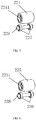
- the caster module 20 includes an effector 21, an omni wheel 22, and a first bearing 23.
- the first bearing 23 is fixed to the omni wheel 22.
- the effector 21 is at least partially inserted into the omni wheel 22, a case of the effector 21 is sleeved onto the first bearing 23, and an output end of the effector 21 is connected to the omni wheel 22.
- the omni wheel 22 may also rotate relative to the case of the effector 21, such that the omni wheel 22 is driven to rotate, and hence functions of movement and steering of the caster module 20 are implemented.
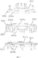
- the omni wheel 22 includes an inner-side hub 221, an omni wheel primary structure 22, an outer-side hub 223, a plurality of inner-side rollers 224, a plurality of outer-side rollers 225, a plurality of second bearings 226, a plurality of third bearings 227, a plurality of outer shaft pins 228, and a plurality of inner shaft pins 229.
- the inner-side roller 224 is provided with an inner through hole 2241.
- One third bearing 227 is fixed to the inner through hole 2241 of one inner-side roller 224.
- One inner shaft pin 229 is inserted into the inner through hole 2241, and sleeved onto the third bearing 227, such that the inner-side roller 224 may rotate about the inner shaft pin 229.
- each inner-side roller 224 may be provided with at least two third bearings 227.
- the two third bearings 227 are disposed at two ends of the through hole 2241 of the inner-side roller 224, and the inner shaft pin 229 is sleeved onto the two third bearings 227, such that the inner-side roller 224 may rotate more stably with less oscillation.
- the outer-side roller 225 is provided with an outer through hole 2251.
- One second bearing 226 is fixed to the outer through hole 2251 of one outer-side roller 225.
- One outer shaft pin 228 is inserted into the outer through hole 2251, and sleeved onto the second bearing 226, such that the outer-side roller 225 may rotate about the outer shaft pin 228.
- each outer-side roller 225 may be provided with at least two second bearings 226.
- the two second bearings 226 are disposed at two ends of the outer through hole 2251 of the outer-side roller 225, and the outer shaft pin 228 is sleeved onto the two second bearings 227, such that the outer-side roller 225 may rotate more stably with less oscillation.
- the omni wheel primary structure 222 includes an omni wheel primary structure body 2221 and a plurality of outer bosses 2222 and first inner bosses 2223 that are defined by extending from the omni wheel primary structure body 2221.
- the omni wheel primary structure 2221 is provided with an shaft groove 2221a, wherein the shaft groove 2221a is provided with an edge.
- An outer ring of the first bearing 23 is in an interference fit to the shaft groove 2221a, and abuts against the edge of the shaft groove 2221a, such that the first bearing 23 is fixed to the shaft groove 2221a.
- the plurality of first inner bosses 2223 are disposed around the omni wheel primary structure body 2221, and a first inner groove 2223a is defined between two adjacent first inner bosses 2223.
- the plurality of first outer bosses 2222 are disposed around the omni wheel primary structure body 2221, and a first outer groove 2222a is defined between two adjacent first outer bosses 2222.
- the first bearing 23 may be connected to the shaft groove 2221a in other fashions other than the above described fashion.
- the first bearing 23 may be connected to the shaft groove 2221a by key connection or pin connection.
- the inner-side hub 221 includes an inner-side hub body 2211 and a plurality of second inner bosses 2212 that are defined by extending from the inner-side hub body 2211.
- the inner-side hub body 2211 is provided with a connecting through hole 2211a.
- the plurality of second inner bosses 2212 are disposed around the inner-side hub body 2211, and a second inner groove 2212a is defined between two adjacent second inner bosses 2212.
- first inner bosses 2223 is the same as the number of second inner bosses 2212, and one first inner boss 2223 is threaded to one second inner boss 2212, such that the inner-side hub 221 is connected to the omni wheel primary structure 222.
- first inner boss 2223 is threaded to the second inner boss 2212, the connecting through hole 2211a is in communication with the shaft groove 2221a, and one first inner groove 2223a is in communication with one second inner groove 2212a, such that an inner rotation groove 221a is collaboratively defined.
- One inner shaft pin 229 is disposed in one inner rotation groove 221a, and two ends of the inner shaft pin 229 are fixed to two opposing side walls of the inner rotation groove 221a, such that one inner-side roller 224 is rotatably connected to one inner rotation groove 221a.
- the inner-side hub 221 may be connected to the omni wheel primary structure 222 in other fashions, for example, welding connection, snap-fitting connection, or the like, other than the above described fashion.
- the inner-side hub 221 and the omni wheel primary structure 222 may collaboratively define the inner rotation groove 221a in other fashions other than the above described fashion, and the inner-side roller 224 may be rotatably connected to the inner rotation groove 221 in other fashions other than the above described fashion, which are not described herein any further.
- the outer-side hub 223 includes an outer-side hub body 2231 and a plurality of second outer bosses 2232 that are defined by extending from the outer-side hub body 2231.
- the plurality of second outer bosses 2232 are disposed around the outer-side hub body 2231, and a second outer groove 2232a is defined by two adjacent outer bosses 2232.
- the number of first outer bosses 2222 is the same as the number of second outer bosses 2232, and one first outer boss 2222 is threaded to one second outer boss 2232, such that the outer-side hub 223 is connected to the omni wheel primary structure 222.
- one first outer groove 2222a is in communication with one second outer groove 2232a, such that an outer rotation groove 223a is collaboratively defined.
- One outer shaft pin 228 is disposed in one outer rotation groove 223a, and two ends of the outer shaft pin 228 are fixed to two opposing side walls of the outer rotation groove 223a, such that one outer-side roller 225 is rotatably connected to one outer rotation groove 223a.
- the outer-side hub 223 may be connected to the omni wheel primary structure 222 in other fashions, for example, welding connection, snap-fitting connection, or the like, other than the above described fashion.
- the inner-side hub 221 and the omni wheel primary structure 222 may collaboratively define the inner rotation groove 221a in other fashions other than the above described fashion, and the inner-side roller 224 may be rotatably connected to the inner rotation groove 221 in other fashions other than the above described fashion, which are not described herein any further.
- the omni wheel 22 may further include an inner gasket 2210 and an outer gasket 220.
- the inner gasket 2210 is sleeved onto the inner shaft pin 229, and the inner gasket 2210 is disposed between the third bearing 227 and the side wall of the inner rotation groove 221a, and configured to stop the third bearing 227 to prevent the third bearing 227 from detaching from the inner shaft pin 229.
- the outer gasket 220 is sleeved onto the outer shaft pin 228, and the outer gasket 220 is disposed between the second bearing 226 and the side wall of the outer rotation groove 223a, and configured to stop the second bearing 226 to prevent the second bearing 226 from detaching from the outer shaft pin 228.
- the effector 21 is inserted into the shaft groove 2221a from the connecting through hole 2211a of the inner-side hub 221, and sleeved onto the first bearing 23 in the shaft groove 2221a, and the output end of the effector 21 is connected to a surface of the outer-side hub 223 facing towards the shaft groove 2221a.
- the output end of the effector 21 rotates, the output end of the effector 21 drives the omni wheel 22 to rotate.
- the effector 21 may be an outer rotor effector, and the output end of the effector 21 may be a flange 211, such that the effector 21 outputs a greater torque.
- flange 211 may also be connected to the outer-side hub 223 by flange threading or welding or the like.
- the caster module may not include the first bearing 23, a gap is defined between the omni wheel primary structure 222 and the case of the effector 21, and the omni wheel primary structure 222 may be rotatable relative to the case of the effector 21.
- an assembling process of the caster module 20 is described as follows: fixing the inner ring of the first bearing 23 to the case of the effector 21; threading the effector 21 to the outer-side hub 223; fixing the outer shaft pin 228 to the inner ring of the second bearing 226; fixing the outer ring of the second bearing 226 to the outer through hole 2251 of the outer-side roller 225; sleeving the outer gasket 220 onto the outer shaft pin 228; threading the omni wheel primary structure 222 to the outer-side hub 223; fixing the inner shaft pin 229 to the inner ring of the third bearing 227; fixing the outer ring of the third bearing 227 to the inner through hole 2241 of the inner-side roller 224; sleeving the gasket 2210 onto the inner shaft pin 229; and threading the omni wheel primary structure 222 to the inner-side hub 221.
- the assembling fashion of the caster module 20 is not limited to the above described assembling process. Other assembling fashions may also apply to the caster module, which are not described herein any further.
- the effector 21 drives the flange 211 to rotate, the flange 211 hence drives the outer-side hub 223 to rotate, the outer-side hub 223 then drives the omni wheel primary structure 222 to rotate, and finally the omni wheel primary structure 222 drives the inner-side hub 221 to rotate.
- the effector 21 is received in the shaft groove 2221a of the omni wheel 22, and the case of the effector 21 is rotatable relative to the inner wall of the shaft groove 2221a; in the meantime, the flange 211 of the effector 21 is fixed to the omni wheel 22, and when the effector 21 drives the flange 211 to rotate, the omni wheel 22 may rotate relative to the effector 21, such that the effector 21 is integrated in the omni wheel 22.
- the caster module 20 occupies a smaller space, and achieves a higher integration degree, such that the robot becomes lighter.
- An embodiment of the present application further provides a robot.
- the robot includes a caster module.
- the caster module has the same structure and functionality as the caster module according to the above embodiment.
Landscapes
- Engineering & Computer Science (AREA)
- Mechanical Engineering (AREA)
- Robotics (AREA)
- Manipulator (AREA)
- Rolling Contact Bearings (AREA)
Claims (9)
- Nachlaufmodul (20), umfassend:ein Omnirad (22), das mit einer Wellennut (2221a) versehen ist; undeinen Effektor (21), der in der Wellennut (2221a) aufgenommen ist, wobei ein Gehäuse des Effektors (21) relativ zu einer inneren Wand der Wellennut (2221a) drehbar ist und ein Ausgabeende des Effektors (21) mit dem Omnirad (22) verbunden und dazu ausgestaltet ist,das Omnirad (22) in Drehung zu versetzen, dadurch gekennzeichnet, dassdas Omnirad (22) eine innenseitige Nabe (221), eine Primärstruktur (222) des Omnirads, eine außenseitige Nabe (223), eine innenseitige Walze (224) und eine außenseitige Walze (225) umfasst; wobeidie Wellennut (2221a) an der Primärstruktur (222) des Omnirads angeordnet ist, die innenseitige Nabe (221) und die außenseitige Nabe (223) beide mit der Primärstruktur (222) des Omnirads verbunden sind, die innenseitige Nabe (221) und die außenseitige Nabe (223) entsprechend an zwei Enden der Wellennut (2221a) angeordnet sind, die innenseitige Nabe (221) und die Primärstruktur (222) des Omnirads gemeinsam eine innere Drehnut (221a) definieren, wobei die innenseitige Walze (224) drehbar mit der inneren Drehnut (221a) verbunden ist, und die außenseitige Nabe (223) und die Primärstruktur (222) des Omnirads gemeinsam eine äußere Drehnut (223a) definieren, wobei die außenseitige Walze (225) drehbar mit der äußeren Drehnut (223a) verbunden ist; unddie innenseitige Nabe (221) mit einer verbindenden Durchgangsöffnung (2211a) versehen ist, die mit der Wellennut (2221a) in Verbindung steht, der Effektor (21) durch die verbindende Durchgangsöffnung (2211a) in die Wellennut (2221a) eingeführt ist und das Ausgabeende des Effektors (21) mit einer Oberfläche der außenseitigen Nabe (223) verbunden ist, die der Wellennut (2221a) zugewandt ist.
- Nachlaufmodul (20) nach Anspruch 1, ferner umfassend ein erstes Lager (23), wobei das erste Lager (23) in der Wellennut (2221a) angeordnet ist, ein äußerer Ring des ersten Lagers (23) an der inneren Wand der Wellennut (2221a) befestigt ist, das Gehäuse des Effektors (21) auf das erste Lager (23) aufgesetzt ist und das Gehäuse des Effektors (21) an einem inneren Ring des ersten Lagers (23) befestigt ist.
- Nachlaufmodul (20) nach Anspruch 1, wobei das Omnirad (22) ferner ein zweites Lager (226) und einen äußeren Wellenstift (228) umfasst; wobei
die außenseitige Walze (225) mit einer äußeren Durchgangsöffnung (2251) versehen ist, das zweite Lager (226) an der äußeren Durchgangsöffnung (2251) befestigt ist; der äußere Wellenstift (228) in die äußere Durchgangsöffnung (2251) eingeführt und auf das zweite Lager (226) aufgesetzt ist und zwei Enden des äußeren Wellenstifts (228) entsprechend an zwei gegenüberliegenden Seitenwänden der äußeren Drehnut (223a) befestigt sind. - Nachlaufmodul (20) nach Anspruch 3, wobei das Omnirad (22) ferner eine äußere Dichtung (220) umfasst, wobei die äußere Dichtung (220) auf ein Ende des äußeren Wellenstifts (228) aufgesetzt ist und die äußere Dichtung (220) zwischen dem zweiten Lager (226) und einer Seitenwand der äußeren Drehnut (223a) angeordnet ist.
- Nachlaufmodul (20) nach Anspruch 1, wobei das Omnirad (22) ferner ein drittes Lager (227) und einen inneren Wellenstift (229) umfasst; wobei
die innenseitige Walze (224) mit einer inneren Durchgangsöffnung (2241) versehen ist, das dritte Lager (227) an der inneren Durchgangsöffnung (2241) befestigt ist; der innere Wellenstift (229) in die innere Durchgangsöffnung (2241) eingeführt und auf das dritte Lager (227) aufgesetzt ist und zwei Enden des äußeren Wellenstifts (228) entsprechend an zwei gegenüberliegenden Seitenwänden der äußeren Drehnut (223a) befestigt sind. - Nachlaufmodul (20) nach Anspruch 5, wobei das Omnirad (22) ferner eine innere Dichtung (2210) umfasst, wobei die innere Dichtung (2210) auf ein Ende des inneren Wellenstifts (229) aufgesetzt ist und die innere Dichtung (2210) zwischen dem dritten Lager (227) und einer Seitenwand der inneren Drehnut (221a) angeordnet ist.
- Nachlaufmodul (20) nach Anspruch 1, wobei die innenseitige Nabe (221) auf die Primärstruktur (222) des Omnirads geschraubt ist und die außenseitige Nabe (223) auf die Primärstruktur (222) des Omnirads geschraubt ist.
- Modul nach einem der Ansprüche 1 bis 7, wobei das Ausgabeende des Effektors (21) ein Flansch ist.
- Roboter, umfassend das Nachlaufmodul (20) nach einem der Ansprüche 1 bis 8.
Applications Claiming Priority (1)
| Application Number | Priority Date | Filing Date | Title |
|---|---|---|---|
| CN201920266830.7U CN209755188U (zh) | 2019-03-01 | 2019-03-01 | 一种轮脚模组及机器人 |
Publications (2)
| Publication Number | Publication Date |
|---|---|
| EP3702173A1 EP3702173A1 (de) | 2020-09-02 |
| EP3702173B1 true EP3702173B1 (de) | 2021-10-27 |
Family
ID=68753363
Family Applications (1)
| Application Number | Title | Priority Date | Filing Date |
|---|---|---|---|
| EP20159686.3A Active EP3702173B1 (de) | 2019-03-01 | 2020-02-27 | Nachlaufmodul und roboter |
Country Status (4)
| Country | Link |
|---|---|
| US (1) | US11498202B2 (de) |
| EP (1) | EP3702173B1 (de) |
| JP (1) | JP6963153B2 (de) |
| CN (1) | CN209755188U (de) |
Families Citing this family (8)
| Publication number | Priority date | Publication date | Assignee | Title |
|---|---|---|---|---|
| EP3705309A1 (de) * | 2019-03-05 | 2020-09-09 | Ecole Polytechnique Federale De Lausanne (EPFL) EPFL-TTO | Motor-rad für einen omnidirektionalen mechanismus und fahrzeug mit dessen verwendung |
| JP1677029S (de) * | 2019-12-09 | 2021-01-18 | ||
| USD928680S1 (en) * | 2019-12-27 | 2021-08-24 | Rotacaster Wheel Pty Ltd. | Multiple directional wheel rim |
| JP7469918B2 (ja) * | 2020-03-13 | 2024-04-17 | 住友重機械工業株式会社 | 駆動装置 |
| USD937336S1 (en) * | 2020-08-24 | 2021-11-30 | Beijing Keyi Technology Co., Ltd. | Snap robot module |
| USD937334S1 (en) * | 2020-08-24 | 2021-11-30 | Beijing Keyi Technology Co., Ltd. | Joint robot module |
| USD937335S1 (en) * | 2020-08-24 | 2021-11-30 | Beijing Keyi Technology Co., Ltd. | Brain robot module |
| USD942518S1 (en) * | 2020-08-24 | 2022-02-01 | Beijing Keyi Technology Co., Ltd. | Two-wheel car robot |
Family Cites Families (13)
| Publication number | Priority date | Publication date | Assignee | Title |
|---|---|---|---|---|
| US6315109B1 (en) * | 1998-04-30 | 2001-11-13 | Stewart & Stephenson Services, Inc. | Split roller wheel and method of assembly |
| JP4003082B2 (ja) * | 2005-07-15 | 2007-11-07 | 株式会社相愛 | 全方向車輪及び全方向移動装置 |
| JP2010260501A (ja) * | 2009-05-11 | 2010-11-18 | Honda Motor Co Ltd | 摩擦式駆動装置及び全方向移動車 |
| DE102011053903A1 (de) * | 2011-09-23 | 2013-03-28 | Zdenek Spindler | Mecanumrad sowie Mecanumradfahrzeug |
| JP5988952B2 (ja) * | 2013-11-14 | 2016-09-07 | 本田技研工業株式会社 | 車輪及び車輪装置及び倒立振子型車両 |
| EP3047771B1 (de) * | 2015-01-20 | 2017-03-15 | Eurofilters Holding N.V. | Staubsaugerroboter |
| CN105730216A (zh) * | 2016-01-12 | 2016-07-06 | 沈阳工业大学 | 一体化全向轮及其控制方法 |
| CN105751815A (zh) * | 2016-04-29 | 2016-07-13 | 广东科杰达智能电器有限公司 | 一种扫地机器人的全向轮 |
| JP2018134917A (ja) | 2017-02-20 | 2018-08-30 | ナブテスコ株式会社 | 運搬台車用の駆動装置 |
| DE102017209356A1 (de) * | 2017-06-01 | 2018-12-06 | Trumpf Medizin Systeme Gmbh + Co. Kg | Laufrad |
| JP3217560U (ja) * | 2017-10-30 | 2018-08-16 | 深▲せん▼市工匠社科技有限公司 | 全方向移動シャーシ |
| US20190126675A1 (en) * | 2017-10-30 | 2019-05-02 | GJS CO.,Ltd | Small double-row omni-directional wheel |
| CN111347823A (zh) * | 2018-12-20 | 2020-06-30 | 沈阳新松机器人自动化股份有限公司 | 一种伺服全向轮 |
-
2019
- 2019-03-01 CN CN201920266830.7U patent/CN209755188U/zh active Active
-
2020
- 2020-02-27 JP JP2020032061A patent/JP6963153B2/ja active Active
- 2020-02-27 EP EP20159686.3A patent/EP3702173B1/de active Active
- 2020-03-02 US US16/806,740 patent/US11498202B2/en active Active
Also Published As
| Publication number | Publication date |
|---|---|
| CN209755188U (zh) | 2019-12-10 |
| US20200276697A1 (en) | 2020-09-03 |
| JP2020138729A (ja) | 2020-09-03 |
| JP6963153B2 (ja) | 2021-11-05 |
| US11498202B2 (en) | 2022-11-15 |
| EP3702173A1 (de) | 2020-09-02 |
Similar Documents
| Publication | Publication Date | Title |
|---|---|---|
| EP3702173B1 (de) | Nachlaufmodul und roboter | |
| US8011735B2 (en) | Wheel for omni-directional vehicle | |
| JP2001208082A (ja) | ピボット軸受 | |
| WO2021054938A1 (en) | Bearing support for parallel electric axle gear assembly | |
| WO2014013753A1 (ja) | 自在キャスター | |
| CN107364279B (zh) | 车辆及其全向轮 | |
| EP3659817B1 (de) | Omnidirektionales kugelrad | |
| US20230331038A1 (en) | Wheel and Mobility Including the Same | |
| CN207106029U (zh) | 车辆及其全向轮 | |
| US7547144B2 (en) | Crossed roller bearing | |
| JP4894020B2 (ja) | 回転体付き車輪 | |
| JP2007196867A (ja) | 全方向走行用車輪及び台車 | |
| JP2010006353A (ja) | 回転体付き車輪 | |
| KR20190067318A (ko) | 구형 볼타입의 옴니 휠 | |
| JP2007205557A (ja) | 転がり軸受、保持器セグメントおよび風力発電機の主軸支持構造 | |
| US20090154860A1 (en) | Tapered roller bearing | |
| JP4807150B2 (ja) | 不思議遊星ローラ式減速機 | |
| EP3934920B1 (de) | Motor-rad für einen omnidirektionalen mechanismus und fahrzeug mit dessen verwendung | |
| CN209793736U (zh) | 一种稳定支撑机械手终端的传动结构 | |
| JPS6114747Y2 (de) | ||
| KR102790666B1 (ko) | 역회전이 원활한 캐스터 | |
| KR102737379B1 (ko) | 볼 베어링을 구비한 캐스터 | |
| KR20130067625A (ko) | 볼캐스터 | |
| CN219507217U (zh) | 一种卷纸托盘 | |
| CN223355299U (zh) | 一种全向轮及割草机器人 |
Legal Events
| Date | Code | Title | Description |
|---|---|---|---|
| PUAI | Public reference made under article 153(3) epc to a published international application that has entered the european phase |
Free format text: ORIGINAL CODE: 0009012 |
|
| STAA | Information on the status of an ep patent application or granted ep patent |
Free format text: STATUS: THE APPLICATION HAS BEEN PUBLISHED |
|
| AK | Designated contracting states |
Kind code of ref document: A1 Designated state(s): AL AT BE BG CH CY CZ DE DK EE ES FI FR GB GR HR HU IE IS IT LI LT LU LV MC MK MT NL NO PL PT RO RS SE SI SK SM TR |
|
| AX | Request for extension of the european patent |
Extension state: BA ME |
|
| STAA | Information on the status of an ep patent application or granted ep patent |
Free format text: STATUS: REQUEST FOR EXAMINATION WAS MADE |
|
| 17P | Request for examination filed |
Effective date: 20210301 |
|
| RBV | Designated contracting states (corrected) |
Designated state(s): AL AT BE BG CH CY CZ DE DK EE ES FI FR GB GR HR HU IE IS IT LI LT LU LV MC MK MT NL NO PL PT RO RS SE SI SK SM TR |
|
| GRAP | Despatch of communication of intention to grant a patent |
Free format text: ORIGINAL CODE: EPIDOSNIGR1 |
|
| STAA | Information on the status of an ep patent application or granted ep patent |
Free format text: STATUS: GRANT OF PATENT IS INTENDED |
|
| RAP1 | Party data changed (applicant data changed or rights of an application transferred) |
Owner name: CLOUDMINDS (SHENZHEN) HOLDINGS CO., LTD. Owner name: CLOUDMINDS (BEIJING) TECHNOLOGIES CO., LTD. |
|
| INTG | Intention to grant announced |
Effective date: 20210722 |
|
| GRAS | Grant fee paid |
Free format text: ORIGINAL CODE: EPIDOSNIGR3 |
|
| GRAA | (expected) grant |
Free format text: ORIGINAL CODE: 0009210 |
|
| STAA | Information on the status of an ep patent application or granted ep patent |
Free format text: STATUS: THE PATENT HAS BEEN GRANTED |
|
| RAP1 | Party data changed (applicant data changed or rights of an application transferred) |
Owner name: CLOUDMINDS ROBOTICS CO., LTD. Owner name: CLOUDMINDS (BEIJING) TECHNOLOGIES CO., LTD. |
|
| AK | Designated contracting states |
Kind code of ref document: B1 Designated state(s): AL AT BE BG CH CY CZ DE DK EE ES FI FR GB GR HR HU IE IS IT LI LT LU LV MC MK MT NL NO PL PT RO RS SE SI SK SM TR |
|
| REG | Reference to a national code |
Ref country code: GB Ref legal event code: FG4D |
|
| REG | Reference to a national code |
Ref country code: CH Ref legal event code: EP |
|
| REG | Reference to a national code |
Ref country code: AT Ref legal event code: REF Ref document number: 1441467 Country of ref document: AT Kind code of ref document: T Effective date: 20211115 |
|
| REG | Reference to a national code |
Ref country code: DE Ref legal event code: R096 Ref document number: 602020000814 Country of ref document: DE |
|
| REG | Reference to a national code |
Ref country code: IE Ref legal event code: FG4D |
|
| REG | Reference to a national code |
Ref country code: LT Ref legal event code: MG9D |
|
| REG | Reference to a national code |
Ref country code: NL Ref legal event code: MP Effective date: 20211027 |
|
| REG | Reference to a national code |
Ref country code: AT Ref legal event code: MK05 Ref document number: 1441467 Country of ref document: AT Kind code of ref document: T Effective date: 20211027 |
|
| PG25 | Lapsed in a contracting state [announced via postgrant information from national office to epo] |
Ref country code: RS Free format text: LAPSE BECAUSE OF FAILURE TO SUBMIT A TRANSLATION OF THE DESCRIPTION OR TO PAY THE FEE WITHIN THE PRESCRIBED TIME-LIMIT Effective date: 20211027 Ref country code: LT Free format text: LAPSE BECAUSE OF FAILURE TO SUBMIT A TRANSLATION OF THE DESCRIPTION OR TO PAY THE FEE WITHIN THE PRESCRIBED TIME-LIMIT Effective date: 20211027 Ref country code: FI Free format text: LAPSE BECAUSE OF FAILURE TO SUBMIT A TRANSLATION OF THE DESCRIPTION OR TO PAY THE FEE WITHIN THE PRESCRIBED TIME-LIMIT Effective date: 20211027 Ref country code: BG Free format text: LAPSE BECAUSE OF FAILURE TO SUBMIT A TRANSLATION OF THE DESCRIPTION OR TO PAY THE FEE WITHIN THE PRESCRIBED TIME-LIMIT Effective date: 20220127 Ref country code: AT Free format text: LAPSE BECAUSE OF FAILURE TO SUBMIT A TRANSLATION OF THE DESCRIPTION OR TO PAY THE FEE WITHIN THE PRESCRIBED TIME-LIMIT Effective date: 20211027 |
|
| PG25 | Lapsed in a contracting state [announced via postgrant information from national office to epo] |
Ref country code: IS Free format text: LAPSE BECAUSE OF FAILURE TO SUBMIT A TRANSLATION OF THE DESCRIPTION OR TO PAY THE FEE WITHIN THE PRESCRIBED TIME-LIMIT Effective date: 20220227 Ref country code: SE Free format text: LAPSE BECAUSE OF FAILURE TO SUBMIT A TRANSLATION OF THE DESCRIPTION OR TO PAY THE FEE WITHIN THE PRESCRIBED TIME-LIMIT Effective date: 20211027 Ref country code: PT Free format text: LAPSE BECAUSE OF FAILURE TO SUBMIT A TRANSLATION OF THE DESCRIPTION OR TO PAY THE FEE WITHIN THE PRESCRIBED TIME-LIMIT Effective date: 20220228 Ref country code: PL Free format text: LAPSE BECAUSE OF FAILURE TO SUBMIT A TRANSLATION OF THE DESCRIPTION OR TO PAY THE FEE WITHIN THE PRESCRIBED TIME-LIMIT Effective date: 20211027 Ref country code: NO Free format text: LAPSE BECAUSE OF FAILURE TO SUBMIT A TRANSLATION OF THE DESCRIPTION OR TO PAY THE FEE WITHIN THE PRESCRIBED TIME-LIMIT Effective date: 20220127 Ref country code: NL Free format text: LAPSE BECAUSE OF FAILURE TO SUBMIT A TRANSLATION OF THE DESCRIPTION OR TO PAY THE FEE WITHIN THE PRESCRIBED TIME-LIMIT Effective date: 20211027 Ref country code: LV Free format text: LAPSE BECAUSE OF FAILURE TO SUBMIT A TRANSLATION OF THE DESCRIPTION OR TO PAY THE FEE WITHIN THE PRESCRIBED TIME-LIMIT Effective date: 20211027 Ref country code: HR Free format text: LAPSE BECAUSE OF FAILURE TO SUBMIT A TRANSLATION OF THE DESCRIPTION OR TO PAY THE FEE WITHIN THE PRESCRIBED TIME-LIMIT Effective date: 20211027 Ref country code: GR Free format text: LAPSE BECAUSE OF FAILURE TO SUBMIT A TRANSLATION OF THE DESCRIPTION OR TO PAY THE FEE WITHIN THE PRESCRIBED TIME-LIMIT Effective date: 20220128 Ref country code: ES Free format text: LAPSE BECAUSE OF FAILURE TO SUBMIT A TRANSLATION OF THE DESCRIPTION OR TO PAY THE FEE WITHIN THE PRESCRIBED TIME-LIMIT Effective date: 20211027 |
|
| REG | Reference to a national code |
Ref country code: DE Ref legal event code: R097 Ref document number: 602020000814 Country of ref document: DE |
|
| PG25 | Lapsed in a contracting state [announced via postgrant information from national office to epo] |
Ref country code: SM Free format text: LAPSE BECAUSE OF FAILURE TO SUBMIT A TRANSLATION OF THE DESCRIPTION OR TO PAY THE FEE WITHIN THE PRESCRIBED TIME-LIMIT Effective date: 20211027 Ref country code: SK Free format text: LAPSE BECAUSE OF FAILURE TO SUBMIT A TRANSLATION OF THE DESCRIPTION OR TO PAY THE FEE WITHIN THE PRESCRIBED TIME-LIMIT Effective date: 20211027 Ref country code: RO Free format text: LAPSE BECAUSE OF FAILURE TO SUBMIT A TRANSLATION OF THE DESCRIPTION OR TO PAY THE FEE WITHIN THE PRESCRIBED TIME-LIMIT Effective date: 20211027 Ref country code: EE Free format text: LAPSE BECAUSE OF FAILURE TO SUBMIT A TRANSLATION OF THE DESCRIPTION OR TO PAY THE FEE WITHIN THE PRESCRIBED TIME-LIMIT Effective date: 20211027 Ref country code: DK Free format text: LAPSE BECAUSE OF FAILURE TO SUBMIT A TRANSLATION OF THE DESCRIPTION OR TO PAY THE FEE WITHIN THE PRESCRIBED TIME-LIMIT Effective date: 20211027 Ref country code: CZ Free format text: LAPSE BECAUSE OF FAILURE TO SUBMIT A TRANSLATION OF THE DESCRIPTION OR TO PAY THE FEE WITHIN THE PRESCRIBED TIME-LIMIT Effective date: 20211027 |
|
| PLBE | No opposition filed within time limit |
Free format text: ORIGINAL CODE: 0009261 |
|
| STAA | Information on the status of an ep patent application or granted ep patent |
Free format text: STATUS: NO OPPOSITION FILED WITHIN TIME LIMIT |
|
| PG25 | Lapsed in a contracting state [announced via postgrant information from national office to epo] |
Ref country code: MC Free format text: LAPSE BECAUSE OF FAILURE TO SUBMIT A TRANSLATION OF THE DESCRIPTION OR TO PAY THE FEE WITHIN THE PRESCRIBED TIME-LIMIT Effective date: 20211027 |
|
| 26N | No opposition filed |
Effective date: 20220728 |
|
| REG | Reference to a national code |
Ref country code: BE Ref legal event code: MM Effective date: 20220228 |
|
| PG25 | Lapsed in a contracting state [announced via postgrant information from national office to epo] |
Ref country code: LU Free format text: LAPSE BECAUSE OF NON-PAYMENT OF DUE FEES Effective date: 20220227 Ref country code: AL Free format text: LAPSE BECAUSE OF FAILURE TO SUBMIT A TRANSLATION OF THE DESCRIPTION OR TO PAY THE FEE WITHIN THE PRESCRIBED TIME-LIMIT Effective date: 20211027 |
|
| PG25 | Lapsed in a contracting state [announced via postgrant information from national office to epo] |
Ref country code: SI Free format text: LAPSE BECAUSE OF FAILURE TO SUBMIT A TRANSLATION OF THE DESCRIPTION OR TO PAY THE FEE WITHIN THE PRESCRIBED TIME-LIMIT Effective date: 20211027 |
|
| PG25 | Lapsed in a contracting state [announced via postgrant information from national office to epo] |
Ref country code: IE Free format text: LAPSE BECAUSE OF NON-PAYMENT OF DUE FEES Effective date: 20220227 |
|
| PG25 | Lapsed in a contracting state [announced via postgrant information from national office to epo] |
Ref country code: BE Free format text: LAPSE BECAUSE OF NON-PAYMENT OF DUE FEES Effective date: 20220228 |
|
| PG25 | Lapsed in a contracting state [announced via postgrant information from national office to epo] |
Ref country code: IT Free format text: LAPSE BECAUSE OF FAILURE TO SUBMIT A TRANSLATION OF THE DESCRIPTION OR TO PAY THE FEE WITHIN THE PRESCRIBED TIME-LIMIT Effective date: 20211027 |
|
| REG | Reference to a national code |
Ref country code: CH Ref legal event code: PL |
|
| PG25 | Lapsed in a contracting state [announced via postgrant information from national office to epo] |
Ref country code: LI Free format text: LAPSE BECAUSE OF NON-PAYMENT OF DUE FEES Effective date: 20230228 Ref country code: CH Free format text: LAPSE BECAUSE OF NON-PAYMENT OF DUE FEES Effective date: 20230228 |
|
| PG25 | Lapsed in a contracting state [announced via postgrant information from national office to epo] |
Ref country code: MK Free format text: LAPSE BECAUSE OF FAILURE TO SUBMIT A TRANSLATION OF THE DESCRIPTION OR TO PAY THE FEE WITHIN THE PRESCRIBED TIME-LIMIT Effective date: 20211027 Ref country code: CY Free format text: LAPSE BECAUSE OF FAILURE TO SUBMIT A TRANSLATION OF THE DESCRIPTION OR TO PAY THE FEE WITHIN THE PRESCRIBED TIME-LIMIT Effective date: 20211027 |
|
| PG25 | Lapsed in a contracting state [announced via postgrant information from national office to epo] |
Ref country code: HU Free format text: LAPSE BECAUSE OF FAILURE TO SUBMIT A TRANSLATION OF THE DESCRIPTION OR TO PAY THE FEE WITHIN THE PRESCRIBED TIME-LIMIT; INVALID AB INITIO Effective date: 20200227 |
|
| PG25 | Lapsed in a contracting state [announced via postgrant information from national office to epo] |
Ref country code: TR Free format text: LAPSE BECAUSE OF FAILURE TO SUBMIT A TRANSLATION OF THE DESCRIPTION OR TO PAY THE FEE WITHIN THE PRESCRIBED TIME-LIMIT Effective date: 20211027 |
|
| PG25 | Lapsed in a contracting state [announced via postgrant information from national office to epo] |
Ref country code: MT Free format text: LAPSE BECAUSE OF FAILURE TO SUBMIT A TRANSLATION OF THE DESCRIPTION OR TO PAY THE FEE WITHIN THE PRESCRIBED TIME-LIMIT Effective date: 20211027 |
|
| PGFP | Annual fee paid to national office [announced via postgrant information from national office to epo] |
Ref country code: GB Payment date: 20260219 Year of fee payment: 7 |
|
| PGFP | Annual fee paid to national office [announced via postgrant information from national office to epo] |
Ref country code: DE Payment date: 20260206 Year of fee payment: 7 |
|
| PGFP | Annual fee paid to national office [announced via postgrant information from national office to epo] |
Ref country code: FR Payment date: 20260227 Year of fee payment: 7 |