EP3705309A1 - Motor-rad für einen omnidirektionalen mechanismus und fahrzeug mit dessen verwendung - Google Patents
Motor-rad für einen omnidirektionalen mechanismus und fahrzeug mit dessen verwendung Download PDFInfo
- Publication number
- EP3705309A1 EP3705309A1 EP19160735.7A EP19160735A EP3705309A1 EP 3705309 A1 EP3705309 A1 EP 3705309A1 EP 19160735 A EP19160735 A EP 19160735A EP 3705309 A1 EP3705309 A1 EP 3705309A1
- Authority
- EP
- European Patent Office
- Prior art keywords
- motor
- wheel
- rollers
- ring
- wheel according
- Prior art date
- Legal status (The legal status is an assumption and is not a legal conclusion. Google has not performed a legal analysis and makes no representation as to the accuracy of the status listed.)
- Withdrawn
Links
Images


Classifications
-
- B—PERFORMING OPERATIONS; TRANSPORTING
- B60—VEHICLES IN GENERAL
- B60K—ARRANGEMENT OR MOUNTING OF PROPULSION UNITS OR OF TRANSMISSIONS IN VEHICLES; ARRANGEMENT OR MOUNTING OF PLURAL DIVERSE PRIME-MOVERS IN VEHICLES; AUXILIARY DRIVES FOR VEHICLES; INSTRUMENTATION OR DASHBOARDS FOR VEHICLES; ARRANGEMENTS IN CONNECTION WITH COOLING, AIR INTAKE, GAS EXHAUST OR FUEL SUPPLY OF PROPULSION UNITS IN VEHICLES
- B60K7/00—Disposition of motor in, or adjacent to, traction wheel
- B60K7/0007—Disposition of motor in, or adjacent to, traction wheel the motor being electric
-
- B—PERFORMING OPERATIONS; TRANSPORTING
- B60—VEHICLES IN GENERAL
- B60B—VEHICLE WHEELS; CASTORS; AXLES FOR WHEELS OR CASTORS; INCREASING WHEEL ADHESION
- B60B19/00—Wheels not otherwise provided for or having characteristics specified in one of the subgroups of this group
- B60B19/003—Multidirectional wheels
Definitions
- the present invention relates to a motor-wheel for a motion mechanism and more particularly to a motor-wheel for an omni-directional motion mechanism and a vehicle using the same.
- Omni-directional motion mechanisms and wheels have been developed mostly in the past forty years. Technically, they have been referred to as "holonomic" wheeled motion mechanisms as they provide three degrees of freedom on a plane.
- Mecanum and omni wheels are the most commonly used wheels in this category. More particularly, an omni or mecanum wheel essentially consists of a wheel with small discs, also called rollers, placed around the circumference of the wheel and which are perpendicular to the turning direction In case of omni directional wheel or angled to the turning direction in case of mecanum wheels. The effect is that the wheel can be driven with full force, but will also slide laterally with great ease.
- the thickness of the wheel should increase which increases the cost.
- rollers which can be easily damaged and which, once damaged, need a replacement of the entire wheel.
- a primary object of the invention is to solve the above-mentioned problems and more particularly to provide omni-directional motion mechanism with more robustness and high modularity.
- the present invention relates to an omni-directional and mecanum wheel which is compatible with hub motors.
- the present invention can be used for holonomic wheeled motion mechanisms, including personal transportation devices, robots, household devices, vehicles etc.
- a preferred embodiment of the present invention uses hub motors or so called "in-wheel motors". Connecting the motor and the wheel is challenging because these motors haven't been used with omni-wheels as the wheels are not made to connect to such motors. There is therefore a need for a product which can be used to connect a hub motor to an omni-wheel.
- the inventors have rebuilt the whole structure of the wheel of the present invention so as to present a ring-shape, with a hollow portion in the center, which gives enough space for housing an in-wheel motor which passes through and gets attached to the wheel. Doing so, it also enhances the robustness of the wheel because the strength of an in-wheel motor's structure is very highly based on the common materials used in these motors. In the present invention, since the motor will carry the pressure and load on the wheel, and since the structure of our wheel is ring-type, it is much stronger in comparison to any other wheel of the prior art.
- the wheel has a ring-shaped structure, most of the volume of the wheel is null and empty. Removing most of the wheel and replacing it with the motor enables to produce a wheel with much less material in comparison to the traditional structure which is disk-shaped. Obviously, when one uses less material, the production cost drops.
- rollers which are preferably independent from each other and detachably fixed to the wheel structure preferably through the use of at least two screws which can be removed so as to remove the damaged roller and replace it with a new one.
- the invention relates to a motor-wheel for an omni-directional motion vehicle, comprising a ring-shaped structure with a central axis, presenting an outer radial surface and an inner radial surface, whereby the outer radial surface comprises a plurality of rollers that are rotatable about an inclined axis relative to the central axis, and the inner radial surface is adapted to be connected to a hub-motor such that the hub-motor is a load bearing element of the wheel.
- the ring-shaped structure comprises two rings adapted to be assembled together so as to sandwich said hub-motor within a housing partially surrounded by their inner radial surfaces.
- each ring presents a plurality of recess portions adapted to receive the rollers. In this manner, the rollers are at least partially protected.
- the motor-wheel comprises two sets of rollers, each set of rollers being mounted on one ring of the ring-shaped structure.
- each set of rollers being mounted on one ring of the ring-shaped structure.
- At least one set of rollers comprises rollers which are independent from each other. In this manner, each roller can be changed one-by-one if damaged.
- At least one set of rollers comprises at least some rollers which are linked to each other through a common rotating axis. In this manner, each roller handling is easy.
- the roller axis is perpendicular to the central axis.
- control is improved.
- the rollers are detachably mounted on the ring shaped structure. In this manner the rollers can be easily replaced.
- the rollers are detachably mounted on the ring-shaped structure through the use of screws.
- the rollers are easily fixed.
- the rollers are detachably mounted on the ring-shaped structure through the use of holders fixed by the screws.
- the rollers are firmly fixed.
- the screws also maintain the two rings together. Therefore, the wheel needs less fixing means.
- the motor-wheel further comprises a hub motor located within the housing partially surrounded by their inner radial surfaces so as to become a load bearing element of the wheel. Therefore, the structural strength of the wheel is increased.
- the hub motor comprises a rotor fixed to the ring shaped structure and a stator comprising a shaft and adapted to be fixed to vehicles. Therefore, the motor is reliable.
- a second aspect of the invention relates to an omni-directional motion vehicle comprising a base plate and at least three motor-wheels according to the first embodiment of the invention.
- the particular advantages of this device of the invention being similar to the ones of the method of the first aspect of the invention, they will not be repeated here.
- the three wheels are disposed in the same horizontal plane and spaced by 120° between them. Therefore, the stability of the vehicle is enhanced.
- This invention has the following advantages:
- the proposed omni-directional wheel of the present invention can be used along with hub-motors.
- the weight of the wheel has been decreased as less material is needed for the production of this wheel compared to any other wheel of the same size.
- the manufacturing cost of the wheel drops as less material is needed for production.
- rollers on the wheel have been designed in a modular manner, and can be replaced one by one in case of damage, without changing the whole wheel. This feature decreases the maintenance cost of the wheel and renders the replacements in the wheel much easier.
- Figures 1A and 1B show an exploded isometric view and an exploded side view of a ring structure 11 of an omni wheel assembly and its connection to rollers 2 with screws 3 and holders 4 according to a first embodiment of the present invention.
- the ring structure presents an inner radial surface 112, recesses 111 for receiving the rollers 2 and holes 113 for receiving the screws 3.
- the rollers 2 are connected to a common shaft 5.
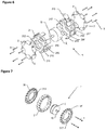
- FIGS 2 and 3 show exploded isometric views of the first embodiment of the omni-directional motor-wheel 1 of the present invention and details the structure of this omni-directional motor-wheel 1 and its connection to a hub-motor 9.
- the hub-motor 9 is surrounded by the ring-shaped structure made of two ring structures 11, 11' and, more particularly, is housed within a hollow housing delimited by the inner radial surface 112, 112' of each ring structures 11, 11' which renders the omni-directional motor-wheel 1 compatible with different kinds of hub-motors 9.
- This structure increases the strength of the motor-wheel 1 as the motor 9 enhances the structural strength of the whole wheel 1 by being placed within the wheel-structure 11, 11' itself.
- FIGS. 2 and 3 show views of a motor-wheel 1 for an omni-directional motion vehicle, comprising a ring-shaped structure made of the ring structures 11, 11' with a central axis, presenting an outer radial surface and an inner radial surface 112, 112', whereby the outer radial surface comprises a plurality of rollers 2, 2' that are rotatable about an inclined axis relative to the central axis, and the inner radial surface 112, 112' is adapted to be connected to a hub-motor 9 such that the hub-motor 9 is a load bearing element of the wheel.
- the motor-wheel actually comprises a hub motor 9 located within the housing partially surrounded by their inner radial surfaces 112, 112' so as to become a load bearing element of the wheel 1.
- the two rings structures 11, 11' are adapted to be assembled together so as to sandwich said hub-motor 9 within the housing partially surrounded by their inner radial surfaces 112, 112' by pressing and pressuring the outer edge of the motor in the middle.
- screws 3, 3' which are used for maintaining the rollers 2, 2' (see below) also maintain the two rings 11, 11' together.
- each ring 11, 11' comprises at least one, preferably but not necessarily threaded, through-hole 113, 113' and a threaded blind-hole 114, 114' such that once pressed together, the through hole 113, 113' of the first ring 11 faces the blind-hole 114', 114 of the second ring 11' and vice-versa so as to provide a continuous hole between the two rings 11, 11' for each screw3, 3'.
- the motor-wheel 1 comprises at least two sets of rollers 2, 2' each set of rollers being mounted on one ring structure 11, 11' of the ring-shaped structure.
- At least one set of rollers 2, 2', or both can comprise at least some rollers, or all rollers, which are linked to each other through a common rotating axis 5.
- at least one set of rollers comprises rollers 2, 2' which are independent from each other, i.e. each roller has his own rotation shaft.
- the present invention is not particularly limited to the type of roller set and that the wheel 1 may have both independent rollers having their own shaft and separated from one another and/or a circular roller assembly having a common shaft, provided that their rotation axis is inclined, preferably perpendicular, to the wheel's central axis and that they are detachable from the ring structure.
- each roller 2, 2' is attached to the corresponding ring using fixing means such as both a holder 4 and a screw 3 (or a plurality of each) where each screw 3, 3' fix the holder 4, 4' on the ring 11, 11' which in turn fix the roller 2, 2' on the ring 11, 11', but the present invention is not limited to that.
- the roller 2, 2' and its shaft, or the rollers 2, 2' and their common shaft 5, 5' are placed in their respective roller place 111, 111' adapted to receive their roller and preferably consists in a recess within the ring structure 11, 11' as explained above.
- the number of roller places 111, 111' is not particularly limited on a ring 11, 11' and mainly depends on the number and/or the length of the rollers 2, 2' and the perimeter of the ring. Additionally, one can attach the rollers 2, 2' by using a single string as the shaft 5, 5' for all rollers as represented in the figures. In this case, the string 5, 5' is possibly merely going through a longitudinal hole through the roller 2, 2' from one end to the other end of the roller. This possibility accelerates the production and the assembly of the rollers.
- the modularity of the structure of the rollers 2, 2' enables the users of the omni-wheel to replace any defected roller without changing the whole structure of the wheel because the rollers and their shaft can have a one piece structure which can be installed and detached independently through the use of at least one roller holder 4, 4' or one screw 3, 3' (or both).
- the maintenance cost of this omni-wheel drops a lot.
- the isometric view of the rollers which are to be placed on the ring around the wheel structure shows that they are adapted to roll passively around their shaft which is preferably orthogonal to the motor shaft.
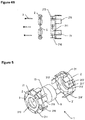
- the holders 4, 4' can be omitted and the ring structure can comprise a groove 216, 216' for receiving the string 5, 5' which is then blocked by the screws 3, 3' as shown in the embodiment of Figures 4a , 4b , 5 and 6 .
- This embodiment also shows a different ring structure where each ring 21, 21' presents a plurality of complementary material extensions 215, 215' adapted to fit into each other and that enhance the robustness of the wheel.
- the screws 3, 3' preferably maintain the two rings 21, 21' together.
- Figure 7 shows an isometric view of the ring structure attached to the hub motor according to a third embodiment of the present invention where the wheel is a mecanum wheel comprising two rings structures 31, 31', rollers 2 and screws 3.
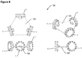
- Figure 8 shows different isometric views of the second aspect of the invention, which is a vehicle 100 in which the motor-wheels 1 of the first, second or third embodiment of the invention can be used for having an omni or mecanum directional motion mechanism. It preferably includes a deck 101 which holds the several shafts 10 of the hub-motors and the three (represented) or more motor-wheel structures 1 as an omni directional vehicle. These three motor-wheels enable the device to move omnidirectionally.
- the vehicle itself is mechanically stable and no gyroscope sensor is needed for the balance.
- three omni wheels of the present invention are shown which are disposed in the same horizontal plane and spaced by 120° between them and each have an in-wheel/hub motor in it and the shaft of the stator of the motor has been detachably/attached to the deck through a lock/unlock mechanism.
Priority Applications (4)
| Application Number | Priority Date | Filing Date | Title |
|---|---|---|---|
| EP19160735.7A EP3705309A1 (de) | 2019-03-05 | 2019-03-05 | Motor-rad für einen omnidirektionalen mechanismus und fahrzeug mit dessen verwendung |
| US17/436,329 US20220169107A1 (en) | 2019-03-05 | 2020-03-04 | Motor-wheel for an omni-directional mechanism and vehicle using the same |
| PCT/EP2020/055694 WO2020178337A1 (en) | 2019-03-05 | 2020-03-04 | Motor-wheel for an omni-directional mechanism and vehicle using the same |
| EP20711524.7A EP3934920B1 (de) | 2019-03-05 | 2020-03-04 | Motor-rad für einen omnidirektionalen mechanismus und fahrzeug mit dessen verwendung |
Applications Claiming Priority (1)
| Application Number | Priority Date | Filing Date | Title |
|---|---|---|---|
| EP19160735.7A EP3705309A1 (de) | 2019-03-05 | 2019-03-05 | Motor-rad für einen omnidirektionalen mechanismus und fahrzeug mit dessen verwendung |
Publications (1)
| Publication Number | Publication Date |
|---|---|
| EP3705309A1 true EP3705309A1 (de) | 2020-09-09 |
Family
ID=65729095
Family Applications (2)
| Application Number | Title | Priority Date | Filing Date |
|---|---|---|---|
| EP19160735.7A Withdrawn EP3705309A1 (de) | 2019-03-05 | 2019-03-05 | Motor-rad für einen omnidirektionalen mechanismus und fahrzeug mit dessen verwendung |
| EP20711524.7A Active EP3934920B1 (de) | 2019-03-05 | 2020-03-04 | Motor-rad für einen omnidirektionalen mechanismus und fahrzeug mit dessen verwendung |
Family Applications After (1)
| Application Number | Title | Priority Date | Filing Date |
|---|---|---|---|
| EP20711524.7A Active EP3934920B1 (de) | 2019-03-05 | 2020-03-04 | Motor-rad für einen omnidirektionalen mechanismus und fahrzeug mit dessen verwendung |
Country Status (3)
| Country | Link |
|---|---|
| US (1) | US20220169107A1 (de) |
| EP (2) | EP3705309A1 (de) |
| WO (1) | WO2020178337A1 (de) |
Families Citing this family (1)
| Publication number | Priority date | Publication date | Assignee | Title |
|---|---|---|---|---|
| CA3043879A1 (en) * | 2019-05-21 | 2020-11-21 | Stephen Sutherland | Shock-tolerant omni wheel |
Citations (5)
| Publication number | Priority date | Publication date | Assignee | Title |
|---|---|---|---|---|
| WO1995000352A1 (fr) * | 1993-06-17 | 1995-01-05 | Hydro-Quebec | Moteur-roue electrique muni d'une bande peripherique |
| RO128285A2 (ro) * | 2011-02-11 | 2013-04-30 | Universitatea Tehnică ''gheorghe Asachi'' Din Iaşi | Vehicul cu patru roţi omnidirecţionale |
| DE102016010374A1 (de) * | 2016-08-26 | 2017-04-06 | Daimler Ag | Fahrzeugrad |
| WO2017164926A1 (en) * | 2016-03-23 | 2017-09-28 | Ford Global Technologie, Llc | Versatile urban electric transport device and system |
| DE102016218674A1 (de) * | 2016-09-28 | 2018-03-29 | Robert Bosch Gmbh | Elektromotorisch angetriebene Radvorrichtung, insbesondere Smartwheel |
Family Cites Families (3)
| Publication number | Priority date | Publication date | Assignee | Title |
|---|---|---|---|---|
| EP3242803B1 (de) * | 2015-01-06 | 2023-06-07 | Rotacaster Wheel Pty Ltd | Radrahmenkomponente |
| CN108438095A (zh) * | 2018-03-19 | 2018-08-24 | 合肥工业大学 | 一种全向护理移动机器人平台 |
| CN109681557B (zh) * | 2018-06-12 | 2023-11-10 | 杭州程天科技发展有限公司 | 减震装置及其轮子结构 |
-
2019
- 2019-03-05 EP EP19160735.7A patent/EP3705309A1/de not_active Withdrawn
-
2020
- 2020-03-04 EP EP20711524.7A patent/EP3934920B1/de active Active
- 2020-03-04 US US17/436,329 patent/US20220169107A1/en active Pending
- 2020-03-04 WO PCT/EP2020/055694 patent/WO2020178337A1/en unknown
Patent Citations (5)
| Publication number | Priority date | Publication date | Assignee | Title |
|---|---|---|---|---|
| WO1995000352A1 (fr) * | 1993-06-17 | 1995-01-05 | Hydro-Quebec | Moteur-roue electrique muni d'une bande peripherique |
| RO128285A2 (ro) * | 2011-02-11 | 2013-04-30 | Universitatea Tehnică ''gheorghe Asachi'' Din Iaşi | Vehicul cu patru roţi omnidirecţionale |
| WO2017164926A1 (en) * | 2016-03-23 | 2017-09-28 | Ford Global Technologie, Llc | Versatile urban electric transport device and system |
| DE102016010374A1 (de) * | 2016-08-26 | 2017-04-06 | Daimler Ag | Fahrzeugrad |
| DE102016218674A1 (de) * | 2016-09-28 | 2018-03-29 | Robert Bosch Gmbh | Elektromotorisch angetriebene Radvorrichtung, insbesondere Smartwheel |
Also Published As
| Publication number | Publication date |
|---|---|
| US20220169107A1 (en) | 2022-06-02 |
| WO2020178337A1 (en) | 2020-09-10 |
| EP3934920C0 (de) | 2023-09-27 |
| EP3934920A1 (de) | 2022-01-12 |
| EP3934920B1 (de) | 2023-09-27 |
Similar Documents
| Publication | Publication Date | Title |
|---|---|---|
| CN100556716C (zh) | 无轮毂脚轮 | |
| US8960339B2 (en) | Mecanum wheel | |
| EP3934920B1 (de) | Motor-rad für einen omnidirektionalen mechanismus und fahrzeug mit dessen verwendung | |
| US4835840A (en) | Method of making an improved disc rotor assembly | |
| CN209755188U (zh) | 一种轮脚模组及机器人 | |
| CN104704721A (zh) | 用于电机的转子组件以及用于生产转子组件的方法 | |
| WO2019080443A1 (zh) | 一种万向轮 | |
| EP3113344B1 (de) | Polkörperstruktur für ein magnetgetriebe | |
| US8525380B2 (en) | Vacuum mechanical rotation-transmitting apparatus | |
| US20140175930A1 (en) | Permanent magnet embedded type rotating electrical machine | |
| CN103423306A (zh) | 滚动轴承 | |
| US10245945B2 (en) | Driving device and wheeled robot having the same | |
| US10145455B2 (en) | Friction-type continuously variable transmission | |
| US11180247B2 (en) | Drone motor and drone comprising same | |
| KR20190043831A (ko) | 드론용 모터 및 이를 포함하는 드론 | |
| JP2010195245A (ja) | 全方位移動用車輪 | |
| CN110667305A (zh) | 一种麦克纳姆全向轮和装配方法 | |
| CN111469602A (zh) | 一种全向轮、全向轮组件及可移动装置 | |
| JP6203522B2 (ja) | 車輪 | |
| CN219544422U (zh) | 轮辐变化的脚轮 | |
| US9434208B2 (en) | Omnidirectional wheel | |
| CN102234782A (zh) | 镀膜伞架 | |
| US20120193972A1 (en) | Bearing positioning device for hub assembly | |
| CN107110257A (zh) | 摩擦制动器结构 | |
| EP3659817B1 (de) | Omnidirektionales kugelrad |
Legal Events
| Date | Code | Title | Description |
|---|---|---|---|
| PUAI | Public reference made under article 153(3) epc to a published international application that has entered the european phase |
Free format text: ORIGINAL CODE: 0009012 |
|
| STAA | Information on the status of an ep patent application or granted ep patent |
Free format text: STATUS: THE APPLICATION HAS BEEN PUBLISHED |
|
| AK | Designated contracting states |
Kind code of ref document: A1 Designated state(s): AL AT BE BG CH CY CZ DE DK EE ES FI FR GB GR HR HU IE IS IT LI LT LU LV MC MK MT NL NO PL PT RO RS SE SI SK SM TR |
|
| AX | Request for extension of the european patent |
Extension state: BA ME |
|
| STAA | Information on the status of an ep patent application or granted ep patent |
Free format text: STATUS: THE APPLICATION IS DEEMED TO BE WITHDRAWN |
|
| 18D | Application deemed to be withdrawn |
Effective date: 20210310 |