EP3701272B1 - Barrette de raccordement - Google Patents
Barrette de raccordement Download PDFInfo
- Publication number
- EP3701272B1 EP3701272B1 EP18796390.5A EP18796390A EP3701272B1 EP 3701272 B1 EP3701272 B1 EP 3701272B1 EP 18796390 A EP18796390 A EP 18796390A EP 3701272 B1 EP3701272 B1 EP 3701272B1
- Authority
- EP
- European Patent Office
- Prior art keywords
- connection strip
- housing
- connection
- plug
- counter
- Prior art date
- Legal status (The legal status is an assumption and is not a legal conclusion. Google has not performed a legal analysis and makes no representation as to the accuracy of the status listed.)
- Active
Links
- 239000004020 conductor Substances 0.000 claims description 18
- 238000004146 energy storage Methods 0.000 claims description 6
- 230000037431 insertion Effects 0.000 claims 2
- 238000003780 insertion Methods 0.000 claims 2
- 230000007935 neutral effect Effects 0.000 description 4
- 230000005611 electricity Effects 0.000 description 3
- 210000003746 feather Anatomy 0.000 description 2
- 230000006835 compression Effects 0.000 description 1
- 238000007906 compression Methods 0.000 description 1
- 230000000881 depressing effect Effects 0.000 description 1
- 239000012777 electrically insulating material Substances 0.000 description 1
- 238000012423 maintenance Methods 0.000 description 1
Images


Classifications
-
- G—PHYSICS
- G01—MEASURING; TESTING
- G01R—MEASURING ELECTRIC VARIABLES; MEASURING MAGNETIC VARIABLES
- G01R1/00—Details of instruments or arrangements of the types included in groups G01R5/00 - G01R13/00 and G01R31/00
- G01R1/02—General constructional details
- G01R1/04—Housings; Supporting members; Arrangements of terminals
- G01R1/0408—Test fixtures or contact fields; Connectors or connecting adaptors; Test clips; Test sockets
- G01R1/0416—Connectors, terminals
-
- G—PHYSICS
- G01—MEASURING; TESTING
- G01R—MEASURING ELECTRIC VARIABLES; MEASURING MAGNETIC VARIABLES
- G01R11/00—Electromechanical arrangements for measuring time integral of electric power or current, e.g. of consumption
- G01R11/02—Constructional details
- G01R11/04—Housings; Supporting racks; Arrangements of terminals
-
- G—PHYSICS
- G01—MEASURING; TESTING
- G01R—MEASURING ELECTRIC VARIABLES; MEASURING MAGNETIC VARIABLES
- G01R22/00—Arrangements for measuring time integral of electric power or current, e.g. electricity meters
- G01R22/06—Arrangements for measuring time integral of electric power or current, e.g. electricity meters by electronic methods
- G01R22/061—Details of electronic electricity meters
- G01R22/065—Details of electronic electricity meters related to mechanical aspects
-
- G—PHYSICS
- G01—MEASURING; TESTING
- G01R—MEASURING ELECTRIC VARIABLES; MEASURING MAGNETIC VARIABLES
- G01R22/00—Arrangements for measuring time integral of electric power or current, e.g. electricity meters
- G01R22/06—Arrangements for measuring time integral of electric power or current, e.g. electricity meters by electronic methods
- G01R22/061—Details of electronic electricity meters
- G01R22/066—Arrangements for avoiding or indicating fraudulent use
-
- H—ELECTRICITY
- H01—ELECTRIC ELEMENTS
- H01R—ELECTRICALLY-CONDUCTIVE CONNECTIONS; STRUCTURAL ASSOCIATIONS OF A PLURALITY OF MUTUALLY-INSULATED ELECTRICAL CONNECTING ELEMENTS; COUPLING DEVICES; CURRENT COLLECTORS
- H01R31/00—Coupling parts supported only by co-operation with counterpart
- H01R31/08—Short-circuiting members for bridging contacts in a counterpart
Definitions
- a meter in the sense of this application is an electricity meter.
- the generic connection strips enable meters to be exchanged without interrupting the power supply to consumers.
- jumper plugs can be attached to the connection strips, which connect the incoming and outgoing phases when plugged in so that the meter can be exchanged without interrupting the power supply.
- Claim 1 creates a connection block for a meter to achieve the object, which advantageously has at least one movable housing element which is in a first position when the meter is plugged into the connection block and which is in a second position without the meter attached.
- the movable housing element is acted upon by an energy storage device with force, which is designed and arranged to move the movable housing element from the first position to the second position when the meter is removed from the terminal block.
- the movable housing element is designed as a hood.
- fastening means such as dovetail projections and / or grooves are formed on the housing of the connection strip in order to arrange an additional device such as the aforementioned safety storage plug there.
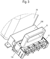
- the reference number 10 denotes a connection strip
- the reference number 20 a (schematically illustrated) meter in particular an electricity meter
- the reference number 30 a jumper plug 30.
- the counter 20 has a housing 200 from which pin contacts 201 protrude (see FIG Fig. 4 and 7th ).
- the connection strip 10 has a housing 100, which preferably consists of an electrically insulating plastic and is in the form of a strip.
- the housing 100 has openings 101 on its side facing the counter 20 and first connection devices 102 on the counter side, assigned to the openings, for conductors, which can be designed as terminal connections.
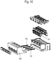
- the jumper plug 30 When the meter is changed, the jumper plug 30 is plugged onto the connection strip 10 in order to ensure uninterrupted operation when the meter 20 is changed.
- the pin contacts 201 are energized until the meter is completely disconnected from the first connection devices 102 for conductors on the meter side.
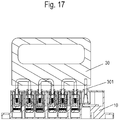
- a movable housing element 104 is arranged on the housing 100. Associated with this movable housing element 104 is an energy storage device which is designed and arranged to move the movable housing element 104 from a first position to a second position when the meter is removed from the terminal strip 10.
- the energy store can be formed by one or more springs 105.
- the movable housing element 104 is designed as a hood.
- the one or more springs 105 are distributed between the movable housing member 104 and the housing 100.
- the springs 105 can be designed as helical springs.
- the housing element 104 is designed and arranged and acted upon by the energy storage device in such a way that it moves over the pin contacts 201 of the counter 20 when the counter is removed. In particular, this movement is such that, due to the sliding-like extension of the housing element 104, there is no risk of touching the contact pins 201 from above or the side - where the housing part 104 is provided for protection - with the finger.
- the movable housing element can also be locked in this position by means of screws (it may then be necessary to use a tool) (not shown). This can also be used to provide additional protection that prevents unintentional or unauthorized depressing of the moving part. Otherwise, the movable housing part can also be secured in other ways, e.g. by means of sufficient spring force. In this way, protection in accordance with protection class IP2XC can be ensured in a simple manner.
- the movable housing element 104 will have several side walls in the manner of a hood and thus offer protection in several directions.
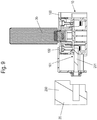
- the first connection devices 102 and the second connection devices 107 are each connected in the housing 100 of the connection strip 10 via one or more busbar sections 108, 109. To Fig. 13 ff the two busbar sections 108, 109 are also conductively connected to one another via a releasable spring contact 110.
- connection devices 101 and 107 can each be designed as clamp connections, in particular as screw connections.
- the busbar sections 108, 109 are each L-shaped here in a side view.
- the jumper plug 30 is designed so that it has a corresponding second plug contact 301 - a total of seven second plug contacts 301 - on a housing 300 for each of the incoming and outgoing phases and to be bridged and preferably the neutral conductor.
- the jumper plug 30 If the jumper plug 30 is placed on the housing 100 of the connection strip 10 and the second plug contacts 301 of the jumper plug 30 are plugged into the housing 100 of the connection strip 10 in the first plug contacts 113, it conductively connects the incoming and outgoing phases and preferably the incoming and outgoing neutral. In this way, the counter 20 can be changed, without the power supply of consumers having to be interrupted.
- the third connection device 112 is further designed in such a way that when the plug contacts 301 of the jumper plug 30 are inserted, the plug contacts 113 of the third connection device 112 after reaching a state in which the corresponding busbars of the incoming and outgoing phases and possibly the neutral conductor are already conductive are connected to one another "bridging", the respective spring contact 110 on the third connection device 112, which connects the two busbar sections 107, 108 each conductively, is released.
- the two busbars 106, 107 are no longer conductively connected to one another.
- the pin contacts 201 of the counter / to the counter in the first connection devices 102 on the counter 10 are thus also voltage-free.
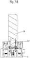
- the spring contact 110 can be implemented in various ways.
- Fig. 21 it has a T-shape with two transverse legs 1101 and 1102 and one longitudinal leg 1103.
- One or more springs 1104 are distributed between the transverse limbs 1101 and 1102 and the longitudinal limb 1103. These press the spring contact 110 into an in Fig. 13 ff. upper position, in which a contact arrangement formed on the longitudinal leg 1103, in particular a spring arrangement, 1105 made of a highly electrically conductive material, conductively connects the two busbars 107, 108, which lead to the first and the second connection device of the connection strip 10, to one another.
- the remaining area of the T-shaped spring contact can consist of an electrically insulating material such as plastic.
- the spring contact 110 is designed and dimensioned in such a way that the electrical contact between the busbar sections 108, 109 is only released after the contact closure of the plug contacts 301 on the bridging plug 30 with the third connection devices 113.
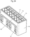
- Figure 22a shows a perspective view of a further meter 20 to which a terminal strip 10 is plugged.
- This terminal block 10 can be one or more Have features of the preceding figures and be designed in the manner of one or more of the claims.
- connection strip again rests on the housing 100.
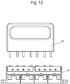
- a safety storage plug 115 for conductors is attached or molded onto this housing 100 here.
- the safety storage plug 115 has a housing 116.
- In the housing 116 are directly or on sliding disks 117 (see also Figure 26a , b ), which can be inserted into the housing 116, which is preferably open on one side, formed connection devices 118 for conductors. These are protected against touching by fingers in the interior of the housing 116 and are accessible - only for the conductor ends - through appropriately dimensioned openings 122 directly in the housing 116 or in the sliding disks 117.
- these connection devices 118 can be designed as direct plug-in connections, for example as push-in connections that have a compression spring.
- connection devices 118 can furthermore be set into an open position by means of an actuating means such as a trigger 119 in order to insert or release a respective conductor. If the conductors are not finely stranded, it is usually also possible to plug them directly into the respective direct plug-in connection.
- corresponding fastening means such as for example dovetail projections 120 and grooves 121 can be formed on the housings 100 and 116.
- Reference signs ⁇ /b> Terminal strip 10 casing 100 openings 101 first connection devices 102 movable housing element 104 feathers 105 openings 106 second connection devices 107 Busbar sections 108, 109 Spring contact 110 openings 111 third connection device 112 first plug contact 113
Landscapes
- Physics & Mathematics (AREA)
- General Physics & Mathematics (AREA)
- Engineering & Computer Science (AREA)
- Power Engineering (AREA)
- Connections Arranged To Contact A Plurality Of Conductors (AREA)
- Switch Cases, Indication, And Locking (AREA)
Claims (10)
- Barrette de raccordement (10) pour un compteur (20), comprenant au moins un élément de boîtier mobile (104) qui se trouve dans une première position quand le compteur (20) est enfiché sur la barrette de raccordement (10) et qui se trouve dans une deuxième position quand il n'y a pas de compteur (20) posé dessus, dans laquelle l'élément de boîtier mobile (104) est soumis à la force d'un accumulateur de force qui est conçu et disposé pour déplacer l'élément de boîtier mobile (104) de la première position à la deuxième quand le compteur (20) est enlevé de la barrette de raccordement (10), caractérisée en ce que l'élément de boîtier mobile (104) est conformé comme un capuchon.
- Barrette de raccordement (10) selon la revendication 1, caractérisée en ce que L'accumulateur de force est formé par un ou plusieurs ressorts (105), de préférence des ressorts hélicoïdaux.
- Barrette de raccordement (10) selon la revendication 2, caractérisée en ce que les un ou plusieurs ressorts (105) sont répartis entre l'élément de boîtier mobile (104) et le boîtier (100).
- Barrette de raccordement (10) selon l'une des revendications précédentes, caractérisée en ce que la barrette de raccordement (10) présente un connecteur de rangement de sécurité (115) pour un ou plusieurs conducteurs.
- Barrette de raccordement (10) selon l'une des revendications précédentes, caractérisée en ce que la barrette de raccordement (10) présente un boîtier (100).
- Barrette de raccordement (10) selon la revendication 5, caractérisée en ce que le connecteur de rangement de sécurité (115) présente un boîtier (116) qui est posé ou formé sur le boîtier (100).
- Barrette de raccordement (10) selon la revendication 6, caractérisée en ce que sont formés dans le boîtier (116), directement ou sur des plaques d'insertion (117) qui peuvent être insérées dans le boîtier (116) ouvert de préférence sur un côté, des dispositifs de raccordement (118) pour des conducteurs qui sont protégés contre le contact des doigts et qui sont accessibles aux conducteurs à travers des ouvertures (122) formées directement dans le boîtier (116) ou dans les plaques d'insertion (117).
- Barrette de raccordement (10) selon la revendication 7, caractérisée en ce que des moyens de fixation en correspondance tels que des saillies en queue d'aronde (120) et des rainures (121) sont formés sur les boîtiers (100) et (116).
- Barrette de raccordement (10) selon l'une des revendications précédentes, caractérisée en ce que des moyens de fixation tels que des saillies en queue d'aronde (120) et des rainures (121) sont formés sur le boîtier (100) de la barrette de raccordement (10) pour y disposer un dispositif supplémentaire.
- Barrette de raccordement (10) selon l'une des revendications précédentes avec un compteur (20) enfiché dessus.
Applications Claiming Priority (2)
| Application Number | Priority Date | Filing Date | Title |
|---|---|---|---|
| DE202017106463 | 2017-10-25 | ||
| PCT/EP2018/079125 WO2019081565A2 (fr) | 2017-10-25 | 2018-10-24 | Barrette de raccordement |
Publications (2)
| Publication Number | Publication Date |
|---|---|
| EP3701272A2 EP3701272A2 (fr) | 2020-09-02 |
| EP3701272B1 true EP3701272B1 (fr) | 2021-06-30 |
Family
ID=64083070
Family Applications (1)
| Application Number | Title | Priority Date | Filing Date |
|---|---|---|---|
| EP18796390.5A Active EP3701272B1 (fr) | 2017-10-25 | 2018-10-24 | Barrette de raccordement |
Country Status (3)
| Country | Link |
|---|---|
| EP (1) | EP3701272B1 (fr) |
| DE (1) | DE202018106082U1 (fr) |
| WO (1) | WO2019081565A2 (fr) |
Families Citing this family (2)
| Publication number | Priority date | Publication date | Assignee | Title |
|---|---|---|---|---|
| DE102018117723B4 (de) * | 2018-07-23 | 2020-06-25 | Klaus Bruchmann Gmbh | Aufnahmeeinheit für kontaktstift in einem zähleranschlussblock sowie zähleranschlussblock und ein stromzähler |
| US11119123B2 (en) * | 2019-03-11 | 2021-09-14 | Honeywell International Inc. | Power meter with movable terminal blocks |
Family Cites Families (15)
| Publication number | Priority date | Publication date | Assignee | Title |
|---|---|---|---|---|
| DE2256373C3 (de) * | 1972-11-17 | 1981-09-03 | Christian Geyer GmbH & Co, 8500 Nürnberg | Anschlußklemmenblock mit Steckverbindungsteil für mit feststehenden Steckerstiften versehene Elektrizitätszähler |
| DE2435414C3 (de) * | 1974-07-23 | 1978-04-06 | Siemens Ag, 1000 Berlin Und 8000 Muenchen | Zähler-Trennklemme |
| DE19613869C2 (de) * | 1996-04-06 | 1999-01-28 | Geyer Ag | Zählersteckklemme |
| DE10216913A1 (de) | 2001-09-12 | 2003-05-22 | Hager Electro Gmbh | Anschlussleiste |
| DE10344736B4 (de) * | 2003-09-09 | 2012-05-03 | Abb Ag | Stromzähleranordnung |
| DE202004006077U1 (de) * | 2004-04-15 | 2004-07-08 | Geyer Ag | Befestigungs- und Kontaktiereinrichtung |
| DE102004022127A1 (de) * | 2004-05-05 | 2005-12-01 | Abb Patent Gmbh | Stromzählereinrichtung |
| DE102004025164A1 (de) * | 2004-05-14 | 2005-12-08 | Geyer Ag | Befestigungs- und Kontaktiereinrichtung |
| DE202004010045U1 (de) * | 2004-06-23 | 2004-10-07 | Geyer Ag | Befestigungs- und Kontaktiereinrichtung für einen elektronischen Elektrizitätszähler |
| DE102004054887A1 (de) * | 2004-06-29 | 2006-01-19 | Hager Electro Gmbh | Sperre zur Blockierung eines Funktionselements |
| DE102004051818B3 (de) * | 2004-10-25 | 2006-08-17 | Siemens Ag | Kupplungsvorrichtung |
| DE102007046640B4 (de) * | 2007-09-27 | 2012-02-16 | Hager Electro Gmbh & Co. Kg | Zählerplatz mit einem Stromzähler und einer neben dem Stromzähler angeordneten Sicherungseinrichtung |
| DE102008062409A1 (de) * | 2008-12-17 | 2010-06-24 | Hager Electro Gmbh & Co. Kg | Stromzähleranschlussinstallation |
| DE102011015697B4 (de) * | 2011-03-31 | 2015-03-26 | Klaus Bruchmann Gmbh | Zählerschaltblock für einen Elektrizitätszähler sowie Vorrichtungen mit einem Zählerschaltblock |
| DE102013101533B4 (de) * | 2013-02-15 | 2017-05-11 | Wago Verwaltungsgesellschaft Mbh | Elektrizitätszähler-Anschlussklemmenblock |
-
2018
- 2018-10-24 EP EP18796390.5A patent/EP3701272B1/fr active Active
- 2018-10-24 WO PCT/EP2018/079125 patent/WO2019081565A2/fr unknown
- 2018-10-24 DE DE202018106082.1U patent/DE202018106082U1/de active Active
Also Published As
| Publication number | Publication date |
|---|---|
| EP3701272A2 (fr) | 2020-09-02 |
| DE202018106082U1 (de) | 2019-01-28 |
| WO2019081565A2 (fr) | 2019-05-02 |
| WO2019081565A3 (fr) | 2019-08-22 |
Similar Documents
| Publication | Publication Date | Title |
|---|---|---|
| EP2255409B1 (fr) | Pont de commutation et unité composée d'au moins deux blocs de jonction électriques et d'un pont de commutation | |
| EP2255410B1 (fr) | Barrette a bornes ou bloc de barrettes a bornes | |
| DE102007022806B3 (de) | Klemmenbauteil | |
| EP2756554B1 (fr) | Borne serre-fils électrique et bloc de bornes serre-fils électriques | |
| EP2965389B1 (fr) | Bloc de fixation | |
| EP2839544B1 (fr) | Bornier de test | |
| EP3176879B1 (fr) | Borne électrique | |
| EP2847829A1 (fr) | Borne de connexion électrique | |
| DE102015103949A1 (de) | Poke Home-Druckknopf-Konnektor | |
| DE202013003925U1 (de) | Zusatzsockel und damit herstellbare Stecksockelbaugruppe | |
| EP3701272B1 (fr) | Barrette de raccordement | |
| DE202014010621U1 (de) | Steckverbinder | |
| EP0079016B1 (fr) | Connexion enfichable avec pont de contact interrupteur | |
| EP2856561B1 (fr) | Borne de raccordement électrique | |
| EP2429037B1 (fr) | Elément de serrage de cadre pour commutateurs électromécaniques doté d'une pièce de raccordement intégrée | |
| DE202016106294U1 (de) | Anschlussvorrichtung mit einer Anschlussklemme für ein Leiterende | |
| DE3609161C2 (fr) | ||
| EP2988312B1 (fr) | Module de fusible | |
| EP3261183A1 (fr) | Contact à ressort | |
| DE102011081037A1 (de) | Anschlussklemme und Schutzschaltgerät | |
| DE102017102241B4 (de) | Steckdosenerweiterung | |
| EP3281215B1 (fr) | Système convertisseur de courant et sectionneur équipé d'un tel système | |
| DE102016122306B4 (de) | Anordnung zur Herstellung eines elektrischen Kontakts und Schaltanlage | |
| EP0339492B1 (fr) | Dispositif pour connecter facultativement des lignes électriques | |
| DE102012215528A1 (de) | Schalter, insbesondere Leistungsschalter für Niederspannungen |
Legal Events
| Date | Code | Title | Description |
|---|---|---|---|
| STAA | Information on the status of an ep patent application or granted ep patent |
Free format text: STATUS: UNKNOWN |
|
| STAA | Information on the status of an ep patent application or granted ep patent |
Free format text: STATUS: THE INTERNATIONAL PUBLICATION HAS BEEN MADE |
|
| PUAI | Public reference made under article 153(3) epc to a published international application that has entered the european phase |
Free format text: ORIGINAL CODE: 0009012 |
|
| STAA | Information on the status of an ep patent application or granted ep patent |
Free format text: STATUS: REQUEST FOR EXAMINATION WAS MADE |
|
| 17P | Request for examination filed |
Effective date: 20200331 |
|
| AK | Designated contracting states |
Kind code of ref document: A2 Designated state(s): AL AT BE BG CH CY CZ DE DK EE ES FI FR GB GR HR HU IE IS IT LI LT LU LV MC MK MT NL NO PL PT RO RS SE SI SK SM TR |
|
| AX | Request for extension of the european patent |
Extension state: BA ME |
|
| DAV | Request for validation of the european patent (deleted) | ||
| DAX | Request for extension of the european patent (deleted) | ||
| GRAP | Despatch of communication of intention to grant a patent |
Free format text: ORIGINAL CODE: EPIDOSNIGR1 |
|
| STAA | Information on the status of an ep patent application or granted ep patent |
Free format text: STATUS: GRANT OF PATENT IS INTENDED |
|
| INTG | Intention to grant announced |
Effective date: 20210416 |
|
| GRAS | Grant fee paid |
Free format text: ORIGINAL CODE: EPIDOSNIGR3 |
|
| GRAA | (expected) grant |
Free format text: ORIGINAL CODE: 0009210 |
|
| STAA | Information on the status of an ep patent application or granted ep patent |
Free format text: STATUS: THE PATENT HAS BEEN GRANTED |
|
| AK | Designated contracting states |
Kind code of ref document: B1 Designated state(s): AL AT BE BG CH CY CZ DE DK EE ES FI FR GB GR HR HU IE IS IT LI LT LU LV MC MK MT NL NO PL PT RO RS SE SI SK SM TR |
|
| REG | Reference to a national code |
Ref country code: CH Ref legal event code: EP |
|
| REG | Reference to a national code |
Ref country code: DE Ref legal event code: R096 Ref document number: 502018005950 Country of ref document: DE Ref country code: AT Ref legal event code: REF Ref document number: 1406811 Country of ref document: AT Kind code of ref document: T Effective date: 20210715 |
|
| REG | Reference to a national code |
Ref country code: IE Ref legal event code: FG4D Free format text: LANGUAGE OF EP DOCUMENT: GERMAN |
|
| REG | Reference to a national code |
Ref country code: LT Ref legal event code: MG9D |
|
| PG25 | Lapsed in a contracting state [announced via postgrant information from national office to epo] |
Ref country code: BG Free format text: LAPSE BECAUSE OF FAILURE TO SUBMIT A TRANSLATION OF THE DESCRIPTION OR TO PAY THE FEE WITHIN THE PRESCRIBED TIME-LIMIT Effective date: 20210930 Ref country code: HR Free format text: LAPSE BECAUSE OF FAILURE TO SUBMIT A TRANSLATION OF THE DESCRIPTION OR TO PAY THE FEE WITHIN THE PRESCRIBED TIME-LIMIT Effective date: 20210630 Ref country code: FI Free format text: LAPSE BECAUSE OF FAILURE TO SUBMIT A TRANSLATION OF THE DESCRIPTION OR TO PAY THE FEE WITHIN THE PRESCRIBED TIME-LIMIT Effective date: 20210630 |
|
| REG | Reference to a national code |
Ref country code: NL Ref legal event code: MP Effective date: 20210630 |
|
| PG25 | Lapsed in a contracting state [announced via postgrant information from national office to epo] |
Ref country code: GR Free format text: LAPSE BECAUSE OF FAILURE TO SUBMIT A TRANSLATION OF THE DESCRIPTION OR TO PAY THE FEE WITHIN THE PRESCRIBED TIME-LIMIT Effective date: 20211001 Ref country code: SE Free format text: LAPSE BECAUSE OF FAILURE TO SUBMIT A TRANSLATION OF THE DESCRIPTION OR TO PAY THE FEE WITHIN THE PRESCRIBED TIME-LIMIT Effective date: 20210630 Ref country code: RS Free format text: LAPSE BECAUSE OF FAILURE TO SUBMIT A TRANSLATION OF THE DESCRIPTION OR TO PAY THE FEE WITHIN THE PRESCRIBED TIME-LIMIT Effective date: 20210630 Ref country code: NO Free format text: LAPSE BECAUSE OF FAILURE TO SUBMIT A TRANSLATION OF THE DESCRIPTION OR TO PAY THE FEE WITHIN THE PRESCRIBED TIME-LIMIT Effective date: 20210930 Ref country code: LV Free format text: LAPSE BECAUSE OF FAILURE TO SUBMIT A TRANSLATION OF THE DESCRIPTION OR TO PAY THE FEE WITHIN THE PRESCRIBED TIME-LIMIT Effective date: 20210630 |
|
| PG25 | Lapsed in a contracting state [announced via postgrant information from national office to epo] |
Ref country code: CZ Free format text: LAPSE BECAUSE OF FAILURE TO SUBMIT A TRANSLATION OF THE DESCRIPTION OR TO PAY THE FEE WITHIN THE PRESCRIBED TIME-LIMIT Effective date: 20210630 Ref country code: SM Free format text: LAPSE BECAUSE OF FAILURE TO SUBMIT A TRANSLATION OF THE DESCRIPTION OR TO PAY THE FEE WITHIN THE PRESCRIBED TIME-LIMIT Effective date: 20210630 Ref country code: NL Free format text: LAPSE BECAUSE OF FAILURE TO SUBMIT A TRANSLATION OF THE DESCRIPTION OR TO PAY THE FEE WITHIN THE PRESCRIBED TIME-LIMIT Effective date: 20210630 Ref country code: PT Free format text: LAPSE BECAUSE OF FAILURE TO SUBMIT A TRANSLATION OF THE DESCRIPTION OR TO PAY THE FEE WITHIN THE PRESCRIBED TIME-LIMIT Effective date: 20211102 Ref country code: RO Free format text: LAPSE BECAUSE OF FAILURE TO SUBMIT A TRANSLATION OF THE DESCRIPTION OR TO PAY THE FEE WITHIN THE PRESCRIBED TIME-LIMIT Effective date: 20210630 Ref country code: EE Free format text: LAPSE BECAUSE OF FAILURE TO SUBMIT A TRANSLATION OF THE DESCRIPTION OR TO PAY THE FEE WITHIN THE PRESCRIBED TIME-LIMIT Effective date: 20210630 Ref country code: ES Free format text: LAPSE BECAUSE OF FAILURE TO SUBMIT A TRANSLATION OF THE DESCRIPTION OR TO PAY THE FEE WITHIN THE PRESCRIBED TIME-LIMIT Effective date: 20210630 Ref country code: SK Free format text: LAPSE BECAUSE OF FAILURE TO SUBMIT A TRANSLATION OF THE DESCRIPTION OR TO PAY THE FEE WITHIN THE PRESCRIBED TIME-LIMIT Effective date: 20210630 |
|
| PG25 | Lapsed in a contracting state [announced via postgrant information from national office to epo] |
Ref country code: PL Free format text: LAPSE BECAUSE OF FAILURE TO SUBMIT A TRANSLATION OF THE DESCRIPTION OR TO PAY THE FEE WITHIN THE PRESCRIBED TIME-LIMIT Effective date: 20210630 |
|
| REG | Reference to a national code |
Ref country code: DE Ref legal event code: R097 Ref document number: 502018005950 Country of ref document: DE |
|
| PG25 | Lapsed in a contracting state [announced via postgrant information from national office to epo] |
Ref country code: DK Free format text: LAPSE BECAUSE OF FAILURE TO SUBMIT A TRANSLATION OF THE DESCRIPTION OR TO PAY THE FEE WITHIN THE PRESCRIBED TIME-LIMIT Effective date: 20210630 |
|
| PLBE | No opposition filed within time limit |
Free format text: ORIGINAL CODE: 0009261 |
|
| STAA | Information on the status of an ep patent application or granted ep patent |
Free format text: STATUS: NO OPPOSITION FILED WITHIN TIME LIMIT |
|
| PG25 | Lapsed in a contracting state [announced via postgrant information from national office to epo] |
Ref country code: AL Free format text: LAPSE BECAUSE OF FAILURE TO SUBMIT A TRANSLATION OF THE DESCRIPTION OR TO PAY THE FEE WITHIN THE PRESCRIBED TIME-LIMIT Effective date: 20210630 |
|
| 26N | No opposition filed |
Effective date: 20220331 |
|
| REG | Reference to a national code |
Ref country code: CH Ref legal event code: PL |
|
| REG | Reference to a national code |
Ref country code: BE Ref legal event code: MM Effective date: 20211031 |
|
| PG25 | Lapsed in a contracting state [announced via postgrant information from national office to epo] |
Ref country code: MC Free format text: LAPSE BECAUSE OF FAILURE TO SUBMIT A TRANSLATION OF THE DESCRIPTION OR TO PAY THE FEE WITHIN THE PRESCRIBED TIME-LIMIT Effective date: 20210630 |
|
| PG25 | Lapsed in a contracting state [announced via postgrant information from national office to epo] |
Ref country code: LU Free format text: LAPSE BECAUSE OF NON-PAYMENT OF DUE FEES Effective date: 20211024 Ref country code: IT Free format text: LAPSE BECAUSE OF FAILURE TO SUBMIT A TRANSLATION OF THE DESCRIPTION OR TO PAY THE FEE WITHIN THE PRESCRIBED TIME-LIMIT Effective date: 20210630 Ref country code: BE Free format text: LAPSE BECAUSE OF NON-PAYMENT OF DUE FEES Effective date: 20211031 |
|
| PG25 | Lapsed in a contracting state [announced via postgrant information from national office to epo] |
Ref country code: LI Free format text: LAPSE BECAUSE OF NON-PAYMENT OF DUE FEES Effective date: 20211031 Ref country code: CH Free format text: LAPSE BECAUSE OF NON-PAYMENT OF DUE FEES Effective date: 20211031 |
|
| PG25 | Lapsed in a contracting state [announced via postgrant information from national office to epo] |
Ref country code: FR Free format text: LAPSE BECAUSE OF NON-PAYMENT OF DUE FEES Effective date: 20211031 |
|
| PG25 | Lapsed in a contracting state [announced via postgrant information from national office to epo] |
Ref country code: IE Free format text: LAPSE BECAUSE OF NON-PAYMENT OF DUE FEES Effective date: 20211024 |
|
| PG25 | Lapsed in a contracting state [announced via postgrant information from national office to epo] |
Ref country code: LT Free format text: LAPSE BECAUSE OF FAILURE TO SUBMIT A TRANSLATION OF THE DESCRIPTION OR TO PAY THE FEE WITHIN THE PRESCRIBED TIME-LIMIT Effective date: 20210630 |
|
| P01 | Opt-out of the competence of the unified patent court (upc) registered |
Effective date: 20230518 |
|
| GBPC | Gb: european patent ceased through non-payment of renewal fee |
Effective date: 20221024 |
|
| PG25 | Lapsed in a contracting state [announced via postgrant information from national office to epo] |
Ref country code: CY Free format text: LAPSE BECAUSE OF FAILURE TO SUBMIT A TRANSLATION OF THE DESCRIPTION OR TO PAY THE FEE WITHIN THE PRESCRIBED TIME-LIMIT Effective date: 20210630 |
|
| PG25 | Lapsed in a contracting state [announced via postgrant information from national office to epo] |
Ref country code: HU Free format text: LAPSE BECAUSE OF FAILURE TO SUBMIT A TRANSLATION OF THE DESCRIPTION OR TO PAY THE FEE WITHIN THE PRESCRIBED TIME-LIMIT; INVALID AB INITIO Effective date: 20181024 |
|
| PG25 | Lapsed in a contracting state [announced via postgrant information from national office to epo] |
Ref country code: GB Free format text: LAPSE BECAUSE OF NON-PAYMENT OF DUE FEES Effective date: 20221024 |
|
| PGFP | Annual fee paid to national office [announced via postgrant information from national office to epo] |
Ref country code: DE Payment date: 20231020 Year of fee payment: 6 |
|
| PG25 | Lapsed in a contracting state [announced via postgrant information from national office to epo] |
Ref country code: MK Free format text: LAPSE BECAUSE OF FAILURE TO SUBMIT A TRANSLATION OF THE DESCRIPTION OR TO PAY THE FEE WITHIN THE PRESCRIBED TIME-LIMIT Effective date: 20210630 |