EP3701271B1 - Probenbehältererkennung - Google Patents
Probenbehältererkennung Download PDFInfo
- Publication number
- EP3701271B1 EP3701271B1 EP18807762.2A EP18807762A EP3701271B1 EP 3701271 B1 EP3701271 B1 EP 3701271B1 EP 18807762 A EP18807762 A EP 18807762A EP 3701271 B1 EP3701271 B1 EP 3701271B1
- Authority
- EP
- European Patent Office
- Prior art keywords
- container
- rack
- image
- sample
- containers
- Prior art date
- Legal status (The legal status is an assumption and is not a legal conclusion. Google has not performed a legal analysis and makes no representation as to the accuracy of the status listed.)
- Active
Links
Images


Classifications
-
- G—PHYSICS
- G01—MEASURING; TESTING
- G01N—INVESTIGATING OR ANALYSING MATERIALS BY DETERMINING THEIR CHEMICAL OR PHYSICAL PROPERTIES
- G01N35/00—Automatic analysis not limited to methods or materials provided for in any single one of groups G01N1/00 - G01N33/00; Handling materials therefor
- G01N35/00584—Control arrangements for automatic analysers
- G01N35/00722—Communications; Identification
- G01N35/00732—Identification of carriers, materials or components in automatic analysers
-
- G—PHYSICS
- G01—MEASURING; TESTING
- G01N—INVESTIGATING OR ANALYSING MATERIALS BY DETERMINING THEIR CHEMICAL OR PHYSICAL PROPERTIES
- G01N35/00—Automatic analysis not limited to methods or materials provided for in any single one of groups G01N1/00 - G01N33/00; Handling materials therefor
- G01N35/02—Automatic analysis not limited to methods or materials provided for in any single one of groups G01N1/00 - G01N33/00; Handling materials therefor using a plurality of sample containers moved by a conveyor system past one or more treatment or analysis stations
- G01N35/04—Details of the conveyor system
-
- G—PHYSICS
- G06—COMPUTING OR CALCULATING; COUNTING
- G06K—GRAPHICAL DATA READING; PRESENTATION OF DATA; RECORD CARRIERS; HANDLING RECORD CARRIERS
- G06K7/00—Methods or arrangements for sensing record carriers, e.g. for reading patterns
- G06K7/10—Methods or arrangements for sensing record carriers, e.g. for reading patterns by electromagnetic radiation, e.g. optical sensing; by corpuscular radiation
- G06K7/14—Methods or arrangements for sensing record carriers, e.g. for reading patterns by electromagnetic radiation, e.g. optical sensing; by corpuscular radiation using light without selection of wavelength, e.g. sensing reflected white light
- G06K7/1404—Methods for optical code recognition
- G06K7/1408—Methods for optical code recognition the method being specifically adapted for the type of code
- G06K7/1413—1D bar codes
-
- G—PHYSICS
- G06—COMPUTING OR CALCULATING; COUNTING
- G06T—IMAGE DATA PROCESSING OR GENERATION, IN GENERAL
- G06T7/00—Image analysis
- G06T7/60—Analysis of geometric attributes
- G06T7/62—Analysis of geometric attributes of area, perimeter, diameter or volume
-
- G—PHYSICS
- G06—COMPUTING OR CALCULATING; COUNTING
- G06V—IMAGE OR VIDEO RECOGNITION OR UNDERSTANDING
- G06V10/00—Arrangements for image or video recognition or understanding
- G06V10/20—Image preprocessing
- G06V10/255—Detecting or recognising potential candidate objects based on visual cues, e.g. shapes
-
- G—PHYSICS
- G06—COMPUTING OR CALCULATING; COUNTING
- G06V—IMAGE OR VIDEO RECOGNITION OR UNDERSTANDING
- G06V10/00—Arrangements for image or video recognition or understanding
- G06V10/40—Extraction of image or video features
- G06V10/44—Local feature extraction by analysis of parts of the pattern, e.g. by detecting edges, contours, loops, corners, strokes or intersections; Connectivity analysis, e.g. of connected components
-
- G—PHYSICS
- G06—COMPUTING OR CALCULATING; COUNTING
- G06V—IMAGE OR VIDEO RECOGNITION OR UNDERSTANDING
- G06V10/00—Arrangements for image or video recognition or understanding
- G06V10/40—Extraction of image or video features
- G06V10/50—Extraction of image or video features by performing operations within image blocks; by using histograms, e.g. histogram of oriented gradients [HoG]; by summing image-intensity values; Projection analysis
- G06V10/507—Summing image-intensity values; Histogram projection analysis
-
- G—PHYSICS
- G06—COMPUTING OR CALCULATING; COUNTING
- G06V—IMAGE OR VIDEO RECOGNITION OR UNDERSTANDING
- G06V10/00—Arrangements for image or video recognition or understanding
- G06V10/70—Arrangements for image or video recognition or understanding using pattern recognition or machine learning
- G06V10/74—Image or video pattern matching; Proximity measures in feature spaces
- G06V10/75—Organisation of the matching processes, e.g. simultaneous or sequential comparisons of image or video features; Coarse-fine approaches, e.g. multi-scale approaches; using context analysis; Selection of dictionaries
- G06V10/751—Comparing pixel values or logical combinations thereof, or feature values having positional relevance, e.g. template matching
-
- G—PHYSICS
- G01—MEASURING; TESTING
- G01N—INVESTIGATING OR ANALYSING MATERIALS BY DETERMINING THEIR CHEMICAL OR PHYSICAL PROPERTIES
- G01N35/00—Automatic analysis not limited to methods or materials provided for in any single one of groups G01N1/00 - G01N33/00; Handling materials therefor
- G01N35/00584—Control arrangements for automatic analysers
- G01N35/00722—Communications; Identification
- G01N35/00732—Identification of carriers, materials or components in automatic analysers
- G01N2035/00742—Type of codes
- G01N2035/00752—Type of codes bar codes
-
- G—PHYSICS
- G01—MEASURING; TESTING
- G01N—INVESTIGATING OR ANALYSING MATERIALS BY DETERMINING THEIR CHEMICAL OR PHYSICAL PROPERTIES
- G01N35/00—Automatic analysis not limited to methods or materials provided for in any single one of groups G01N1/00 - G01N33/00; Handling materials therefor
- G01N35/02—Automatic analysis not limited to methods or materials provided for in any single one of groups G01N1/00 - G01N33/00; Handling materials therefor using a plurality of sample containers moved by a conveyor system past one or more treatment or analysis stations
- G01N35/04—Details of the conveyor system
- G01N2035/0401—Sample carriers, cuvettes or reaction vessels
- G01N2035/0403—Sample carriers with closing or sealing means
-
- G—PHYSICS
- G01—MEASURING; TESTING
- G01N—INVESTIGATING OR ANALYSING MATERIALS BY DETERMINING THEIR CHEMICAL OR PHYSICAL PROPERTIES
- G01N35/00—Automatic analysis not limited to methods or materials provided for in any single one of groups G01N1/00 - G01N33/00; Handling materials therefor
- G01N35/02—Automatic analysis not limited to methods or materials provided for in any single one of groups G01N1/00 - G01N33/00; Handling materials therefor using a plurality of sample containers moved by a conveyor system past one or more treatment or analysis stations
- G01N35/04—Details of the conveyor system
- G01N2035/0401—Sample carriers, cuvettes or reaction vessels
- G01N2035/0412—Block or rack elements with a single row of samples
-
- G—PHYSICS
- G01—MEASURING; TESTING
- G01N—INVESTIGATING OR ANALYSING MATERIALS BY DETERMINING THEIR CHEMICAL OR PHYSICAL PROPERTIES
- G01N35/00—Automatic analysis not limited to methods or materials provided for in any single one of groups G01N1/00 - G01N33/00; Handling materials therefor
- G01N35/02—Automatic analysis not limited to methods or materials provided for in any single one of groups G01N1/00 - G01N33/00; Handling materials therefor using a plurality of sample containers moved by a conveyor system past one or more treatment or analysis stations
- G01N35/04—Details of the conveyor system
- G01N2035/0474—Details of actuating means for conveyors or pipettes
- G01N2035/0491—Position sensing, encoding; closed-loop control
- G01N2035/0493—Locating samples; identifying different tube sizes
-
- G—PHYSICS
- G06—COMPUTING OR CALCULATING; COUNTING
- G06T—IMAGE DATA PROCESSING OR GENERATION, IN GENERAL
- G06T2207/00—Indexing scheme for image analysis or image enhancement
- G06T2207/10—Image acquisition modality
- G06T2207/10141—Special mode during image acquisition
- G06T2207/10144—Varying exposure
Definitions
- a sample analyzer typically uses a sample presentation unit (SPU) for supporting and transferring a sample rack which holds a plurality of sample containers, such as sample tubes or cups.
- SPU sample presentation unit
- Typical SPUs allow only a single type of container to be held in a single sample rack. Problems can occur when another type of sample container is accidentally loaded into the rack by a user, or when containers in the rack are obstructed or not loaded into the proper position in the rack.
- US 2009/324032 A1 describes a system for identifying test tube types and properties in a sample handling machine using visual information automatically obtained by an optical imager and then processed using vision processing methods.
- the system includes an optical imager positioned to capture images containing one or more test tubes in a rack and a microcontroller programmed to extract predetermined regions of interest and interpret the optical information in the image to decipher the dimension of the test tubes, determine the presence or absence of caps on the test tubes, decode any encoded data, and interpret custom symbologies.
- the system may then determine the nature of the test tubes or other containers presented before the image and provide that information to the sample handling machine to assist with processing of samples.
- WO 2015/191702 A1 describes methods and systems for detecting properties of sample tubes in a laboratory environment which include a drawer vision system that can be trained and calibrated.
- Images of a tube tray captured by at least one camera are analyzed to extract image patches that allow a processor to automatically determine if a tube slot is occupied, if the tube has a cap, and if the tube has a tube top cup.
- the processor can be trained using a random forest technique and a plurality of training image patches. Cameras can be calibrated using a three-dimensional calibration target that can be inserted into the drawer.
- US 2007/134131 A1 describes a pathology distribution system which is provided for automated sample container distribution.
- the system comprises a loading station for loading samples in primary containers of different types, a sample handling station for receiving the containers and identifying the container types and samples therein, and a container distribution station for distributing the containers in areas or racks in the distribution station marked for analyzing processes prescribed for the samples therein.
- a sample presentation unit in a sample analyzer is configured to recognize sample container types in a rack.
- FIG. 1 is a top plan view of an example sample analyzer.
- the sample analyzer is generally designated as reference number 100 and configured to analyze a sample.
- the sample analyzer 100 includes a sample rack 102, a sample presentation unit (SPU) 104, a sample pipettor transfer unit 106, an analytic unit 108, and a sample container recognition unit 110.
- SPU sample presentation unit
- SPU sample pipettor transfer unit
- the rack 102 is configured to hold and transfer one or more sample containers 180.
- the rack 102 can be used in various applications and configured to transfer one or more containers 180 within or outside the sample analyzer 100.
- one or more sample containers 180 can be positioned in the rack 102 in various combinations.
- one or more sample containers 180 can be individually inserted and engaged with the rack 102.
- a single rack 102 is illustrated in this example, it is understood that the sample analyzer 100 is configured to support a plurality of racks 102, which can be used in various combinations in the sample analyzer 100 and operated either individually or in any combination.
- the SPU 104 operates to support the rack 102 and transfer the rack 102 to various locations. An example operation of the rack 102 is further described and illustrated with reference to FIGS. 2-9 .
- the sample pipettor transfer unit 106 operates to draw samples from the containers in the racks 102 and transfer the samples to the analytic unit for analysis.
- the sample pipettor transfer unit 106 contains a disposable tip, a mandrel for holding the tip, a sensor for level sensing fluid, a pump for aspirating fluid and/or dispensing fluid, and tubing/valves. This pipettor function is to aspirate fluid from sample containers or vessels and deliver it to other vessels for analysis.
- the analytic unit 108 operates to analyze the samples originally introduced to the sample analyzer 100 in the containers 180 on the racks 102.
- the analytic unit 108 includes subsystems to transfer vessels, dispense reagents, mix, wash, deliver substrate, and read the chemiluminescence reaction light intensity.
- the sample container recognition unit 110 operates to recognize types of containers 180 in the racks 102.
- An example of the sample container recognition unit 110 is illustrated and described herein.
- FIGS. 2-4 an example operation of the rack 102 is illustrated, which holds and transfers one or more sample containers 180 in the sample analyzer 100.
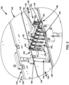
- FIG. 2 depicts a perspective view of an exemplary rack 102 installed at a first position in the SPU of the sample analyzer 100.
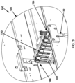
- FIG. 3 depicts the perspective view of the rack at a second position in the SPU, and
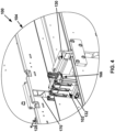
- FIG. 4 depicts the perspective view of the rack at a third position where the rack is partially moved out of the second position of the SPU.
- the rack 102 is located in an onload lane 124 in FIG. 2 , at an intersection of the onload lane 124 and a presentation lane 128 in FIG. 3 , and in the presentation lane 128 in FIG. 4 .
- the rack 102 is loaded with one or more sample containers 180 before the rack 102 is loaded into the sample analyzer 100 (e.g., the SPU 104 thereof). In other embodiments, the rack 102 is loaded with one or more sample containers 180 after the rack 102 has been loaded into the sample analyzer 100 (e.g., the SPU 104 thereof). In yet other embodiments, the rack 102 is partially loaded with one or more sample containers 180 before the rack 102 is loaded into the sample analyzer 100, and one or more additional sample containers 180 can be loaded into the rack 102 afterwards.
- the SPU 104 operates to transfer the rack 102, thereby transferring the sample containers 180 held in the rack 102.
- the SPU 104 is configured to transfer the rack 102 to various locations or stations in the sample analyzer 100.
- the SPU 104 includes a lateral movement section 120 (i.e., an onload-offload lane) and a transverse movement section 122 (i.e., a presentation lane).
- the lateral movement section 120 is substantially perpendicular to the transverse movement section 122.
- the lateral movement section 120 includes an onload lane 124 and an offload lane 126.
- a presentation lane 128 of the transverse movement section 122 is positioned between the onload lane 124 and the offload lane 126.
- the lateral movement section 120 includes a pusher 130 to advance the rack 102 along the onload lane 124 and the offload lane 126.
- the transverse movement section 122 includes a carrier 132 to advance the rack 102 along the presentation lane 128.
- the onload lane 124 includes a first rail 136 (i.e., onload back rail) and a second rail 138 (i.e., onload front rail).
- the presentation lane 128 includes a third rail 140 (i.e., a carrier back rail, a first hook holder, etc.) and a fourth rail 142 (i.e., carrier front rail, a second hook holder, etc.).
- the offload lane 126 includes a fifth rail 144 (i.e., offload back rail) and a sixth rail 146 (i.e., offload front rail).
- the first rail 136 and the fifth rail 144 are aligned with each other.
- the second rail 138 and the sixth rail 146 are aligned with each other and are substantially parallel to the first rail 136 and the fifth rail 144.
- the carrier 132 is at a receiving position (e.g., see FIG. 2 )
- the third rail 140 is aligned with the first rail 136 and the fifth rail 144
- the fourth rail 142 is aligned with the second rail 138 and the sixth rail 146.
- the rack 102 can include a mounting feature configured to load the rack 102 into the SPU 104.
- the mounting feature includes a first hook 160 arranged at a first end 164 and a second hook 162 arranged at a second end 166 opposite to the first end 164.
- the first hook 160 is engaged with the rail 136, 140, and/or 144
- the second hook 162 is engaged with the rail 138, 142, and/or 146.
- a handle 168 (see, e.g., FIG. 2 ) is provided to the rack 102 and may be manually grasped by an operator.
- the rack 102 may be loaded into the SPU 104 via automated means (e.g., by a robot, a pick-and-place apparatus, etc.).
- the racks 102 When a plurality of the racks 102 are held by the SPU 104, the racks 102 are typically loaded into the SPU 104 at the onload lane 124.
- the racks 102 may thus be stacked within the SPU 104.
- a front 150 of one of the racks 102 may abut a rear 152 of another of the racks 102.
- the front 150 of one of the racks 102 may abut the rear 152 of another of the racks 102 positioned ahead of it, and the rear 152 of the one of the racks 102 may abut the front 150 of another of the racks 102 positioned behind it.
- a pattern of abutting racks 102 may thus be formed into a stack.
- a rear 152 of a rearmost rack 102 may abut the pusher 130.
- One or more of the racks 102 may be loaded into the SPU 104 at a time.
- the first hook 160 may be engaged with the rail 136
- the second hook 162 may be engaged with the rail 138 to load the racks 102 into the onload lane 124.
- the pusher 130 may be retracted (e.g., moved away from the already positioned racks 102) and thereby make room for the newly added rack(s) 102.
- the pusher 130 may be advanced (e.g., moved toward the racks 102) and thereby remove any excess room between the pusher 130 and the rack(s) 102.
- One or more of the racks 102 may be loaded into the SPU 104 ahead of, in the middle of, or behind the rack(s) 102 already positioned within the SPU 104.
- the pusher 130 may advance the rack(s) 102 and thereby position at least one of the rack(s) 102 into the presentation lane 128 when the carrier 132 is at the receiving position (e.g., see movement between FIGS. 2 and 3 ).
- the first hook 160 transfers engagement from the rail 136 to the rail 140
- the second hook 162 transfers engagement from the rail 138 to the rail 142.
- the carrier 132 may advance from the receiving position and thereby advance at least one of the rack(s) 102 along the presentation lane 128 (e.g., see movement between FIGS. 3 and 4 ) further into the sample analyzer 100.
- sample(s) within one or more sample containers may be withdrawn and/or otherwise processed and/or analyzed by and/or within the sample analyzer 100.
- the carrier 132 may retract from the predetermined position to the receiving position and thereby withdraw the at least one of the rack(s) 102 along the presentation lane 128 (e.g., see movement between FIGS. 4 and 3 ) from the sample analyzer 100.
- the carrier 132 positions the at least one of the rack(s) 102 along the lateral movement section 120.
- the pusher 130 may then advance the rack(s) 102 and thereby position the at least one of the rack(s) 102 into the offload lane 126 when the carrier 132 is at the receiving position (e.g., see movement between FIGS. 2 and 3 , but with the pusher 130 or a stack of the racks 102 pushing the at least one of the rack(s) 102 out of the carrier 132 and into the offload lane 126).
- the first hook 160 transfers engagement from the rail 140 to the rail 144
- the second hook 162 transfers engagement from the rail 142 to the rail 146.
- additional rack(s) 102 may be similarly ejected from the carrier 132 into the offload lane 126 and thereby push the at least one of the rack(s) 102 along the offload lane 126.
- the racks 102 may similarly be driven off of an end of the offload lane 126 (e.g., into a waste receptacle) and thereby be unloaded from the sample analyzer 100.
- the first hook 160 may be disengaged from the rail 136, 140, and/or 144, and the second hook 162 may be disengaged from the rail 138, 142, and/or 146.
- the handle 168 may be manually grasped by the operator.
- the rack 102 may be unloaded from the SPU 104 via automated means (e.g., by a robot, a pick-and-place apparatus, etc.).
- a plurality of the racks 102 may be simultaneously held by the offload lane 126 (similar to the onload lane 124).
- the racks 102 are typically unloaded from the SPU 104 at the offload lane 126.
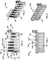
- FIGS. 5-8 examples of the rack 102 are illustrated, which is loaded with containers 180.
- FIG. 5 is an elevation view of an example tube rack
- FIG. 6 is a perspective view of the tube rack of FIG. 5.
- FIG. 7 is an elevation view of an example cup rack
- FIG. 8 is a perspective view of the cup rack of FIG. 7 .
- the rack 102 includes rack slots 190 which can be loaded with containers 180.
- the rack slots 190 can define container positions 334 as illustrated in FIG. 21A-21C below.
- the rack 102 includes a tube rack 102A as illustrated in FIGS. 5 and 6 .
- the tube rack 102A is loaded tubes 182 (i.e., examples of the containers 180) having different sizes, such as first tubes 182A, second tubes 182B, and third tubes 182C.
- one of the rack slots 190 is left empty in the tube rack 102A.
- different types of tubes 182 can be identified by the sample container recognition unit 110.
- the rack 102 includes a cup rack 102B as illustrated in FIGS. 7 and 8 .
- the cup rack 102B is loaded with cups 184 (i.e., examples of the containers 180) having different sizes, such as a first cup 184A, a second cup 184B, and a third cup 184C.
- cups 184 i.e., examples of the containers 180
- four of the rack slots 190 are left empty in the cup rack 102B.
- different types of cups 184 can be identified by the sample container recognition unit 110.
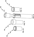
- FIGS. 10-13 illustrate various types of sample cups 184. As illustrated, sample cups 184 may be of various types, and the cup rack 102B is configured to receive such sample cups 184 of different dimensions.
- sample container recognition unit 110 is described with respect to the rack 102.
- the sample container recognition unit 110 is primarily illustrated with respect to the tube rack 102A. It is understood, however, that the sample container recognition unit 110 can also be used and operated similarly with respect to the cup rack 102B.
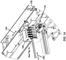
- FIG. 14 is a perspective view of the tube rack 102 located in the presentation lane 128 of the SPU 104.
- FIG. 15 is an enlarged view of the tube rack 102 of FIG. 14 .
- the tube rack 102 is shown partially in view of a camera unit of the sample container recognition unit 110.
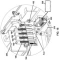
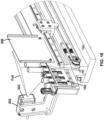
- FIG. 16 is another perspective view of the tube rack 102 located in the presentation lane 128 of the SPU 104 partially in view of the camera unit of the sample container recognition unit 110.
- FIG. 17 is yet another perspective view of the tube rack 102 located in the presentation lane 128 of the SPU 104 partially in view of a container detection unit of the sample container recognition unit 110.
- the sample container recognition unit 110 operates to identify the containers 180 in the rack 102 and detect various characteristics associated with the containers 180, which are used to determine the types of the containers 180. For example, the sample container recognition unit 110 operates to detect a container barcode 186 provided to a container 180. The container barcode 186 is used to verify the container 180 in the rack 102, as described herein. The container barcode 186 can be provided to any suitable location of the container 180. In the illustrated examples of FIGS. 5, 6 , and 15 , the container barcode 186 is provided to an exterior of the sample tube 182. The container barcode 186 can be similarly provided to an exterior of the sample cup 184.
- the sample container recognition unit 110 operates to identify the rack 102.
- the sample container recognition unit 110 operates to detect a rack barcode 188 provided to the rack 102.
- the rack barcode 188 is used to verify the rack 102 as described herein.
- the rack barcode 188 can be provided to any suitable location of the rack 102. In the illustrated examples of FIGS. 5, 6 , and 15 , the rack barcode 188 is arranged on the front of the rack 102 adjacent to the first end 164 of the rack 102. Other locations in the rack 102 are also possible for the rack barcode 188.
- the rack barcode 188 can be provided on the tube racks 102A and/or the cup racks 102B.
- the sample container recognition unit 110 includes a camera unit 202, a container detection unit 204, a screen 206, and a computing device 208.
- the camera unit 202 can be secured to the SPU 104 using a mounting bracket 210.
- the camera unit 202 operates to detect and identify the rack 102 and the containers 180 in the rack 102, and determine characteristics of the rack 102 and the containers 180 therein. Such characteristics of the containers 180 can be used to identify types of the containers 180, as discussed herein.
- the camera unit 202 is arranged in front of the rack 102 that is movable relative to the camera unit 202.
- the camera unit 202 can operate to read barcodes associated with the rack 102 and the containers 180 therein. Further, the camera unit 202 operates to locate, analyze, and inspect the rack 102 and the containers 180 therein.
- the camera unit 202 can be connected to the computing device 208 for various processes.
- One example of the camera unit 202 includes ADVANTAGE 100 SERIES, which is available from Cognex Corporation (Natick, MA).
- the camera unit 202 can be supported in the sample analyzer 100 with the mounting bracket 210.
- the mounting bracket 210 is configured to space the camera unit 202 from the rack 102 and to position the camera unit 202 relative to transient location(s) of the rack 102 to enable the camera unit 202 to have a field of view (FOV) on the container 180 and/or rack 102 being examined.
- An example of the mounting bracket 210 is further described and illustrated with reference to FIG. 18 .
- the camera unit 202 can include a light source 203, such as a LED light, which is operable to emit light toward the rack 102 (and toward the screen 206).
- the screen 206 is used to cast light back in the direction of the field of view (FOV) of the camera unit 202 by reflecting light toward the camera's aperture.
- ADVANTAGE 102 such as part number ADV102-CQBCKFS1-B, which is available from Cognex Corporation (Natick, MA).
- the container detection unit 204 operates to detect whether a container 180 is present in the rack 102.
- the container detection unit 204 is arranged to scan the rack 102 as the rack 102 moves relative to the container detection unit 204.
- the container detection unit 204 is arranged at one side of the rack 102 while the other side of the rack 102 faces the camera unit 202.
- the container detection unit 204 can detect the rack 102 partially or entirely and determine whether any container position (e.g., the container positions 334 as illustrated in FIGS. 21A-21C ) of the rack 102 is empty or not.
- the container detection unit 204 includes a photosensor of various types.
- the container detection unit 204 includes a reflector-type photosensor (also referred to as a reflective photointerrupter or a photoreflector), which positions a light emitting element and a light receiving element on the same surface (so that they face the same direction) and is configured to detect presence and position of an object based on the reflected light from a target object.
- a reflector-type photosensor also referred to as a reflective photointerrupter or a photoreflector
- GP2A25J0000F Series which is available from Sharp Corporation (Osaka, Japan).
- photosensors can also be used for the container detection unit 204, such as a photointerrupter (also referred to as a transmission-type photosensor), which consists of a light emitting element and a light receiving element aligned facing each other in a single package, and which works by detecting light blockage when a target object comes between both of the elements.
- a photointerrupter also referred to as a transmission-type photosensor
- a transmission-type photosensor which consists of a light emitting element and a light receiving element aligned facing each other in a single package, and which works by detecting light blockage when a target object comes between both of the elements.
- the screen 206 is arranged and used with the camera unit 202 to improve image capturing of the camera unit 202.
- the screen 206 is arranged to be opposite to the camera unit 202 so that the rack 102 is positioned between the camera unit 202 and the screen 206.
- the screen 206 is used to cast light back in the direction of the field of view (FOV) of the camera unit by reflecting light toward the camera's aperture.
- FOV field of view
- the screen 206 is made of one or more various materials which can provide different reflection intensities. Further, the screen 206 includes a material configured to increase a scanning range of barcodes. For example, the screen 206 includes a retroreflective sheeting, one example of which includes 3M TM Scotchlite TM Sheeting 7610, available from 3M Company (Maplewood, MN).
- 3M TM Scotchlite TM Sheeting 7610 available from 3M Company (Maplewood, MN).
- the computing device 208 is connected to the camera unit 202 and operates to process the data transmitted from the camera unit 202, such as image processing and evaluation.
- the computing device 208 is connected to the container detection unit 204 and operates to detect whether a container is present in the rack.
- the computing device 208 can include at least some of the components included in an example computing device as illustrated and described with reference to FIG. 34 .
- the computing device 208 executes a software application that processes and evaluates images from the camera unit 202 and determines various characteristics associated with the rack 102 and/or the containers 180 in the rack 102.
- a software application is Cognex In-Sight Vision Software, available from Cognex Corporation (Natick, MA), which provides various tools, such as edge detection (“Edge”), pattern matching (“Pattern Match”), histogram analysis (“Histogram”), and barcode detection (“ReadIDMax”).
- the mounting bracket 210 is configured to arrange the camera unit 202 in front of the rack 102 and to face the front 150 of the rack 102.
- the camera unit 202 is spaced apart from the front 150 of the rack 102 at a distance L1, which can range from about 100 mm to about 200 mm while the rack 102 has a height H1 which can range from about 50 mm to about 100 mm.
- the height H1 of the rack 102 can be defined as a distance between a bottom 156 and a top 158 of the rack 102 (see also FIG. 5 ).
- the mounting bracket 210 is configured to support the camera unit 202 at an angle A relative to the bottom 156 of the rack 102 such that the field of view (FOV) covers the entire height of the containers 180 received in the rack 102.
- the angle A can range from about 90 degrees to about 120 degrees, in some embodiments. Other ranges for the distance L1, the height H1, and the angle A are also possible in other embodiments.
- FIG. 19 is a flowchart of an example method 300 for performing sample container recognition with respect to a rack 102.
- the method 300 can be at least partially performed by the sample container recognition unit 110 with associated devices in the sample analyzer 100.
- the method 300 is described with reference also with FIGS. 20-23 .
- the method 300 can start at operation 302 in which the rack 102 is operated to move toward a first image position 330A with respect to the sample container recognition unit 110.
- the rack 102 is movable to a plurality of predetermined image positions 330 relative to the sample container recognition unit 110 so that different portions of the rack 102 are viewed and captured by the sample container recognition unit 110.
- the camera unit 202 of the sample container recognition unit 110 can have a field of view (FOV) that is limited to only a portion of the rack 102. Therefore, to examine the entire rack 102 (i.e., all rack slots 190 of the rack 102), the rack 102 is moved relative to the camera unit 220 so that the camera unit 220 captures a plurality of images at a plurality of positions (i.e., the image positions 330).
- FOV field of view
- Each of the images shows a portion of the rack 102 at a particular position (i.e., a particular image position) of the rack 102.
- Each portion (i.e., rack portion 332) of the rack 102 can include one or more container positions 334 in which one or more containers 180 are received, respectively.
- the container positions 334 of the rack 102 correspond to the rack slots 190 of the rack 102.
- the rack 102 has three image positions 330 (such as a first image position 330A, a second image position 330B, and a third image position 330C).
- the camera unit 202 is configured to have a field of view (FOV) that captures a portion (i.e., a rack portion) 332 of the rack 102.
- FOV field of view
- the camera unit 202 can capture an image of a first rack portion 332A when the rack 102 is in the first image position 330A, an image of a second rack portion 332B when the rack 102 is in the second image position 330B, and an image of a third rack portion 332C when the rack 102 is in the third image position 330C.
- the image of each rack portion 332 can show one or more container positions 334.
- a first image 350 is captured when the rack 102 is in the first image position 330A.
- the first image 350 shows the first rack portion 332A of the rack 102 that includes first and second container positions 334A and 334B in the rack 102.
- a second image 352 is captured when the rack 102 is in the second image position 330B.
- the second image 352 shows the second rack portion 332B of the rack 102 that includes third and fourth container positions 334C and 334D in the rack 102.
- a third image 354 is captured when the rack 102 is in the third image position 330C.
- the third image 354 shows the third rack portion 332C of the rack 102 that includes fifth, sixth, and seventh container positions 334E, 334F, and 334G in the rack 102.
- the images 350, 352, and 354 captured by the camera unit 202 of the sample container recognition unit 110 can be low exposure monochromatic images.
- the images 350, 352, and 354 illustrated in FIGS. 21A-21C are for the tube rack 102A with sample tubes 182.
- FIG. 22 illustrates an image 356 of a portion of the cup rack 102B with sample cups 184.
- the container detection unit 204 can operate to perform container presence detection.
- the rack portion 332A is a portion of the rack 102 that is included in a field of view (FOV) of the camera unit 202 of the sample container recognition unit 110 at or adjacent the first image position 330A.
- the container detection unit 204 can operate to detect the container presence in the rack portion (e.g., the first rack portion 332A) of the rack 102 as the rack 102 moves toward the first image position 330A.
- the container presence can be detected when the rack 102 is located adjacent or at the first image position 330A.
- the method 300 determines whether any container 180 is present in the rack portion 332A of the rack 102. If any container 180 is present ("YES” at this operation), the method 300 moves on to operation 308. If no container 180 is detected (“NO” at this operation), the method 300 moves to operation 316 in which the rack 102 moves to a next image position 330 (e.g., 330B after 330A). As such, if no container is found at a particular image position 330, the rack 102 can bypass that particular image position. For example, the rack 102 can skip to a next image position 330 without performing container recognition operations (such as operations 308 and 310) at the particular image position, thereby saving time and resources.
- container recognition operations such as operations 308 and 3
- the sample container recognition unit 110 operates to detect one or more container barcodes 186 associated with the containers 180.
- the sample container recognition unit 110 can further operate to verify the containers 180 based on the detected container barcodes 186.
- the rack 102 stops at the image position 330 for the barcode detection.
- the sample container recognition unit 110 e.g., the camera unit 202 thereof
- the image 340 is a high exposure monochromatic image for barcode detection.
- the sample container recognition unit 110 operates to identify the container barcodes 186 in the image 340 and read the container barcodes 186 to verify the containers 180 (i.e., the sample tubes 182 in this example). As illustrated with rectangular boxes 344 in FIG. 23B , the container barcodes 186 are identified in the image 340.
- Various image processing methods can be used to identify and read the container barcodes.
- One example of such image processing methods is Cognex In-Sight Vision Software, available from Cognex Corporation (Natick, MA), which provides various tools, such as edge detection (“Edge”), pattern matching ("Pattern Match”), histogram analysis (“Histogram”), and barcode detection (“ReadIDMax”).
- the sample container recognition unit 110 can operate to detect a rack barcode 188 provided to the rack 102, and verify the rack 102 based on the rack barcode 188.
- the rack barcode 188 is detected and read in a similar manner to the container barcode 186 as described above.
- the image 340 captured by the sample container recognition unit 110 e.g., the camera unit 202 thereof
- the sample container recognition unit 110 operates to identify the rack barcodes 188 in the image 340 and read the rack barcodes 188 to verify the containers 180.
- the rack barcode 188 is identified in the image 340.
- Various image processing methods can be used to identify and read the rack barcode.
- One example of such image processing methods is Cognex In-Sight Vision Software, available from Cognex Corporation (Natick, MA), which provides various tools, such as edge detection (“Edge”), pattern matching (“Pattern Match”), histogram analysis (“Histogram”), and barcode detection (“ReadIDMax”).
- the sample container recognition unit 110 operates to determine characteristics of the containers 180.
- the rack 102 remains stationary for determining the container characteristics.
- the sample container recognition unit 110 operates to process the images of the rack 102 with containers 180 (such as the images 350, 352, 354, and 356 in FIGS. 21A-21C and 22 ), and determine various characteristics associated with the containers 180, such as the dimension (e.g., height and width) of each container and the presence of a cap on the container. Such characteristics can be used to identify the type of the container, as described in more detail below.
- Various image processing methods can be used to determine such characteristics of the containers in the rack.
- Cognex In-Sight Vision Software available from Cognex Corporation (Natick, MA), which provides various tools, such as edge detection (“Edge”), pattern matching (“Pattern Match”), histogram analysis (“Histogram”), and barcode detection (“ReadIDMax”).
- the method 300 moves to operation 314 in which the rack 102 is moved to another location within or outside the sample analyzer 100 for subsequent processes. Otherwise (“NO” at this operation), the method 300 moves to operation 316 in which the rack 102 moves to a next image position 330 (e.g., 330B after 330A). As the rack 102 moves to the next image position 330 or when the rack 102 is at or adjacent the next image position 330, the operation 304 and the subsequent operations are performed as described above. In some embodiments, when the operation 304 and the subsequent operations are performed, the rack barcode reading (such as illustrated in the operation 308) may be omitted if it has already been done once.
- FIG. 24 is a flowchart of another example method 400 for performing sample container recognition with respect to a rack 102.
- the method 400 can be at least partially performed by the SPU 104, the sample container recognition unit 110, and/or other devices in the sample analyzer 100.
- the method 400 can begin at operation 402 in which the rack 102 is moved to enter the presentation lane 128.
- the carrier 132 operates to advance the rack 102 to the presentation lane 128, such as a movement from a position illustrated in FIG. 3 to a position illustrated in FIG. 4 .
- the rack 102 is oriented to move toward the sample container recognition unit 110 along the presentation lane 128 such that a first rack portion 332A (including first and second container positions 334A and 334B in this example) of the rack 102 first approaches toward the sample container recognition unit 110.
- the sample container recognition unit 110 operates the container detection unit 204 to detect presence of any container 180 in the first rack portion 332A of the rack 102.
- the operation 404 is performed similarly to the operation 304 in FIG. 19 .
- the first rack portion 332A of the rack 102 includes a first container position 334A and a second container position 334B, and therefore, the container detection unit 204 operates to detect whether either of the first container position 334A and the second container position 334B is occupied by a container 180, or whether both of the first container position 334A and the second container position 334B are occupied by containers 180, respectively.
- the container detection unit 204 performs the first fly-by check on the presence of containers in the first rack portion 332A of the rack 102 as the rack 102 is introduced into the presentation lane 128 and moving toward a first image position 330A, such as illustrated in FIG. 17 .
- the container detection unit 204 can include one or more sensors of various types.
- the container detection unit 204 includes a photosensor of various types.
- the container detection unit 204 includes a reflector-type photosensor (also referred to as a reflective photointerrupter or a photoreflector), which positions a light emitting element and a light receiving element on the same surface (so that they face the same direction) and is configured to detect presence and position of an object based on the reflected light from a target object.
- a reflector-type photosensor also referred to as a reflective photointerrupter or a photoreflector
- GP2A25J0000F Series which is available from Sharp Corporation (Osaka, Japan).
- Other types of photosensors can also be used for the container detection unit 204.
- the sample container recognition unit 110 operates to store information representing that the rack includes at least one container therein. For example, the sample container recognition unit 110 operates to set a container presence flag ("At Least One Container Present Flag") to true if the rack 102 (e.g., the first rack portion 332A thereof) is determined to include one or two containers 180 at the operation 404.
- a container presence flag "At Least One Container Present Flag"
- the rack 102 continues to move to the first image position 330A and stops at the first image position 330A.
- the carrier 132 operates to continuously move the rack 102 to the first image position 330A and stops the rack 102 thereat.
- the first image position 330A can be a position of the rack 102 relative to the camera unit 202 where the container(s) 180 secured at the first container portion 332A, which include the first and second container positions 334A and 334B, can be at least partially captured by the camera unit 202, as illustrated in FIGS. 21A and 23A .
- the rack barcode 188 provided to the rack 102 is also viewed in the first image position 330A.
- the sample container recognition unit 110 operates the camera unit 202 to read a container barcode 186 of each container 180 received in the first rack portion 332A of the rack 102 (which includes the first container position 334A and/or the second container position 334B).
- the operation 410 is similar to the operation 308 in FIG. 19 .
- the camera unit 202 operates to capture an image (such as the first image 350 in FIG. 21A ) of the first rack portion 332A of the rack 102, and the image is processed to detect and read the container barcodes 186 of the containers 180 at the first and second container positions 334A and 334B (as illustrated in FIGS. 23A and 23B ).
- the sample container recognition unit 110 can identify the containers 180 based on the detected container barcodes 186.
- the sample container recognition unit 110 can store the identification information of the containers 180 (e.g., container ID(s)).
- the sample container recognition unit 110 operates to compare the detected container barcodes 186 with information provided by the user (e.g., a user input of information about the containers, which can be received through an input device of the sample analyzer 100), and determine if the container barcodes 186 matches the user input.
- the sample container recognition unit 110 can operate to store information representing that a particular container position 334 (e.g., 334A and/or 334B) includes a container 180 that does not match the user input.
- the sample container recognition unit 110 can operate to flag the container position 334 of the rack 102 (e.g., the first container position 334A and/or the second container position 334B) that holds the container with the unmatched container barcode 186.
- the sample container recognition unit 110 further operates the camera unit 202 to read the rack barcode 188 of the rack 102.
- the rack barcode 188 is provided adjacent to the first rack portion 332A of the rack 102 (near the first end 164 of the rack 102). Therefore, the image (such as the first image 350 in FIG. 21A ) of the first rack portion 332A of the rack 102 includes the rack barcode 188 of the rack 102.
- the sample container recognition unit 110 processes the image to detect and read the rack barcode 188 of the rack 102.
- the sample container recognition unit 110 can identify the rack 102 based on the detected rack barcode 188.
- the sample container recognition unit 110 can store the identification information of the rack 102 (e.g., rack ID).
- Various image processing methods can be used to identify and read the barcodes 186 and 188.
- One example of such image processing methods is Cognex In-Sight Vision Software, available from Cognex Corporation (Natick, MA), which provides various tools, such as edge detection (“Edge”), pattern matching (“Pattern Match”), histogram analysis (“Histogram”), and barcode detection (“ReadIDMax”).
- the sample container recognition unit 110 can operate to determine whether the rack barcode 188 as detected is valid. If the rack barcode 188 is determined to be valid ("YES” at this operation), the method 400 proceeds to operation 414. Otherwise (“NO” at this operation), the method 400 skips to operation 448 in which the rack 102 is moved to the offload lane 126.
- the sample analyzer 100 can operate to alert the user to the invalidity of the rack as determined at the operation 412. The alert can be of various types, such as a visual and/or audible alarm or notification through the sample analyzer 100.
- the sample container recognition unit 110 can operate the camera unit 202 to determine characteristics of the container(s) 180 at the first rack portion 332A of the rack 102.
- the operation 414 is performed similarly to the operation 310 in FIG. 19 .
- the sample container recognition unit 110 operates to process the image (such as the first image 350 in FIG. 21A ) of the first rack portion 332A of the rack 102, and determine various characteristics associated with the containers 180, such as the dimension (e.g., height and width) of each container and the presence of a cap on the container. Such characteristics can be used to identify the type of the container, as described in more detail below.
- An example detailed method for performing the operation 414 is described and illustrated with reference to FIG. 25 .
- the sample container recognition unit 110 can operate the camera unit 202 to determine characteristics of the rack 102, similarly to the determination of the container characteristics.
- the image (such as the first image 350 in FIG. 21A ) of the first rack portion 332A of the rack 102 can be processed to determine the rack characteristics.
- the rack barcode 188 identified from the captured image can be used to determine the rack characteristics.
- the data of the container characteristics and/or the rack characteristics obtained above can be stored in the sample container recognition unit 110.
- the sample container recognition unit 110 can store information representing that a particular container position 334 (e.g., 334A and/or 334B) includes a container 180 that does not match the user input.
- the sample container recognition unit 110 can operate to flag the container position 334 of the rack 102 (e.g., the first container position 334A and/or the second container position 334B) that holds the container with such undesirable characteristics.
- the rack 102 is operated to move toward the second image position 330B.
- the second image position 330B can be a position of the rack 102 relative to the camera unit 202 where the container(s) 180 secured at the second container portion 332B, which include the third and fourth container positions 334C and 334D, can be at least partially captured by the camera unit 202, as illustrated in FIGS. 21B .
- the sample container recognition unit 110 operates the container detection unit 204 to detect presence of any container 180 in the second rack portion 332B of the rack 102.
- the operation 418 is performed similarly to the operation 304 in FIG. 19 , or the operation 404 above.
- the second rack portion 332B of the rack 102 includes the third container position 334C and the fourth container position 334D, and therefore, the container detection unit 204 operates to detect whether either of the third container position 334C and the fourth container position 334D is occupied by a container 180, or whether both of the third container position 334C and the fourth container position 334D are occupied by containers 180, respectively.
- the container detection unit 204 performs the second fly-by check on the presence of containers in the second rack portion 332B of the rack 102 as the rack 102 is moving toward the second image position 330B.
- the sample container recognition unit 110 operates to store information representing that the rack includes at least one container therein. For example, the sample container recognition unit 110 operates to set the container presence flag ("At Least One Container Present Flag") to true if the rack 102 (e.g., the second rack portion 332B thereof) is determined to include one or two containers 180 at the operation 418.
- the container presence flag "At Least One Container Present Flag"
- the method 400 determines whether any container is present at the second rack portion 332B of the rack 102 (e.g., either or both of the third container position 334C and the fourth container position 334D). If the presence of any container is determined at the second rack portion 332B ("YES"), the method 400 continues to operation 424. Otherwise (“NO”), the method 400 skips to operation 448.
- the rack 102 is stopped and made stationary at the second image position 330B.
- the sample container recognition unit 110 operates the camera unit 202 to read a container barcode 186 of each container 180 received in the second rack portion 332B of the rack 102 (which includes the third container position 334A and/or the fourth container position 334D).
- the operation 418 is similar to the operation 308 in FIG. 19 , or the operation 410 above.
- the camera unit 202 operates to capture an image (such as the second image 352 in FIG. 21B ) of the second rack portion 332B of the rack 102, and the image is processed to detect and read the container barcodes 186 of the containers 180 at the third and fourth container positions 334C and 334D.
- the sample container recognition unit 110 can identify the containers 180 based on the detected container barcodes 186.
- the sample container recognition unit 110 can store the identification information of the containers 180 (e.g., container ID(s)).
- the sample container recognition unit 110 operates to compare the detected container barcodes 186 with information provided by the user (e.g., a user input of information about the containers, which can be received through an input device of the sample analyzer 100), and determine if the container barcodes 186 matches the user input.
- the sample container recognition unit 110 can operate to store information representing that a particular container position 334 (e.g., 334C and/or 334D) includes a container 180 that does not match the user input.
- the sample container recognition unit 110 can operate to flag the container position 334 of the rack 102 (e.g., the first container position 334C and/or the second container position 334D) that holds the container with the unmatched container barcode 186.
- the sample container recognition unit 110 further operates to cross check if the containers 180 identified at the second image position 330B match (or be compatible with) the identification of the rack 102 (e.g., the rack ID found at the operation 410).
- the sample container recognition unit 110 can operate the camera unit 202 to determine characteristics of the container(s) 180 at the second rack portion 332B of the rack 102.
- the operation 414 is performed similarly to the operation 310 in FIG. 19 or the operation 414 above.
- the sample container recognition unit 110 operates to process the image (such as the second image 352 in FIG. 21B ) of the second rack portion 332B of the rack 102, and determine various characteristics associated with the containers 180, such as the dimension (e.g., height and width) of each container and the presence of a cap on the container. Such characteristics can be used to identify the type of the container, as described in more detail below. An example detailed method for performing the operation 428 is described and illustrated with reference to FIG. 25 .
- the data of the container characteristics obtained above can be stored in the sample container recognition unit 110.
- the sample container recognition unit 110 can store information representing that a particular container position 334 (e.g., 334C and/or 334D) includes a container 180 that does not match the user input.
- the sample container recognition unit 110 can operate to flag the container position 334 of the rack 102 (e.g., the third container position 334C and/or the fourth container position 334D) that holds the container with such undesirable characteristics.
- the rack 102 is operated to move toward the third image position 330C.
- the third image position 330C can be a position of the rack 102 relative to the camera unit 202 where the container(s) 180 secured at the third container portion 332C, which include the fifth, sixth, and seventh container positions 334E, 334F, and 334G, can be at least partially captured by the camera unit 202, as illustrated in FIGS. 21C .
- the sample container recognition unit 110 operates the container detection unit 204 to detect presence of any container 180 in the third rack portion 332C of the rack 102.
- the operation 432 is performed similarly to the operation 304 in FIG. 19 , or the operation 404 or 418 above.
- the third rack portion 332C of the rack 102 includes the fifth container position 334E, the sixth container position 334F, and the seventh container position 334G, and therefore, the container detection unit 204 operates to detect whether any or all of the fifth container position 334E, the sixth container position 334F, and the seventh container position 334G are occupied by a container or containers 180.
- the container detection unit 204 performs the third fly-by check on the presence of containers in the third rack portion 332C of the rack 102 as the rack 102 is moving toward the third image position 330C.
- the sample container recognition unit 110 operates to store information representing that the rack includes at least one container therein. For example, the sample container recognition unit 110 operates to set the container presence flag ("At Least One Container Present Flag") to true if the rack 102 (e.g., the third rack portion 332B thereof) is determined to include one or two containers 180 at the operation 432.
- the container presence flag "At Least One Container Present Flag"
- the sample container recognition unit 110 operates to determine the status (either true or false) of the container presence flag ("At Least One Container Present Flag"). If the status is true ("True), the method 400 goes on to operation 438. Otherwise (“False”), the method 400 skips to operation 448.
- any container is present at the third rack portion 332C of the rack 102 (e.g., any or all of the fifth container position 334E, the sixth container position 334F, and the seventh container position 334G). If the presence of any container is determined at the third rack portion 332C ("YES"), the method 400 continues to operation 440. Otherwise (“NO"), the method 400 skips to operation 446.
- the rack 102 is stopped and made stationary at the third image position 330C.
- the sample container recognition unit 110 operates the camera unit 202 to read a container barcode 186 of each container 180 received in the third rack portion 332C of the rack 102 (which includes the fifth container position 334E, the sixth container position 334F, and the seventh container position 334G).
- the operation 418 is similar to the operation 308 in FIG. 19 , or the operation 410 or 426 above.
- the camera unit 202 operates to capture an image (such as the third image 354 in FIG. 21C ) of the third rack portion 332C of the rack 102, and the image is processed to detect and read the container barcodes 186 of the containers 180 at the fifth container position 334E, the sixth container position 334F, and the seventh container position 334G.
- the sample container recognition unit 110 can identify the containers 180 based on the detected container barcodes 186.
- the sample container recognition unit 110 can store the identification information of the containers 180 (e.g., container ID(s)).
- the sample container recognition unit 110 operates to compare the detected container barcodes 186 with information provided by the user (e.g., a user input of information about the containers, which can be received through an input device of the sample analyzer 100), and determine if the container barcodes 186 matches the user input.
- the sample container recognition unit 110 can operate to store information representing that a particular container position 334 (e.g., 334E, 334F, and/or 334G) includes a container 180 that does not match the user input.
- the sample container recognition unit 110 can operate to flag the container position 334 of the rack 102 (e.g., the fifth container position 334E, the sixth container position 334F, and/or the seventh container position 334G) that holds the container with the unmatched container barcode 186.
- the container position 334 of the rack 102 e.g., the fifth container position 334E, the sixth container position 334F, and/or the seventh container position 334G
- the sample container recognition unit 110 further operates to cross check if the containers 180 identified at the third image position 330C match (or be compatible with) the identification of the rack 102 (e.g., the rack ID found at the operation 410).
- the sample container recognition unit 110 can operate the camera unit 202 to determine characteristics of the container(s) 180 at the third rack portion 332C of the rack 102.
- the operation 414 is performed similarly to the operation 310 in FIG. 19 or the operation 414 or 428 above.
- the sample container recognition unit 110 operates to process the image (such as the third image 354 in FIG. 21C ) of the third rack portion 332C of the rack 102, and determine various characteristics associated with the containers 180, such as the dimension (e.g., height and width) of each container and the presence of a cap on the container. Such characteristics can be used to identify the type of the container, as described in more detail below. An example detailed method for performing the operation 444 is described and illustrated with reference to FIG. 25 .
- the data of the container characteristics obtained above can be stored in the sample container recognition unit 110.
- the sample container recognition unit 110 can store information representing that a particular container position 334 (e.g., 334E, 334F, and/or 334G) includes a container 180 that does not match the user input.
- the sample container recognition unit 110 can operate to flag the container position 334 of the rack 102 (e.g., the fifth container position 334E, the sixth container position 334F, and/or the seventh container position 334G) that holds the container with such undesirable characteristics.
- the rack 102 is moved to an aliquoting and/or pipetting system for sample processing.
- the information outputted to the aliquoting and/or pipetting system from the SPU with the sample container recognition unit 110 includes information about the barcodes, which can be used to prioritize sample aspiration and indicate types of sample (e.g., low volume, STAT, and calibration samples).
- the information from the SPU with the sample container recognition unit 110 can further include vision information, such as types of containers, which can be determined from a library of container types.
- the information that can be provided to the sample pipettor may include a starting position to start level sensing to detect liquid (top of container), a maximum allowable depth of travel during aspiration (liquid dead volume or bottom of container), and an internal geometry of sample container (useful for accurate aspiration in cause any further offsets required of the SPU and the pipettor).
- the rack 102 is moved to the offload lane 126.
- the sample analyzer 100 can operate to alert the user to various pieces of information, such as the invalidity of the rack as determined at the operation 412, the status (i.e., false) of the container presence flag as determined at the operation 436, or the end of the sample processing as performed at the operation 446.
- the alert can be of various types, such as a visual and/or audible alarm or notification through the sample analyzer 100.
- the rack 102 can bypass that particular image position. For example, the rack 102 can skip to a next image position 330 without performing container recognition operations at the particular image position.
- the bypass algorithm around the vision checks can save time.
- the main instrument has a cycle time (e.g., 8 seconds), and the SPU operation is partially independent of the main instrument, but ideally finishes within 8 seconds. For example, if a number improper racks are present, then bypassing allows them to be cleared quickly. Therefore, thanks to the bypassing, the main instrument does not need to wait for the SPU to complete its operation.
- FIG. 25 is a flowchart of an example method 500 for processing an image of a rack with one or more containers and determining characteristics of the containers therein.
- the method 500 is used to perform the operations 414, 428, and 444 as described in FIG. 24 .
- the method 500 can be at least partially performed by the SPU 104, the sample container recognition unit 110, and/or other devices in the sample analyzer 100.
- the method 300 is described with reference also with FIGS. 26-32 .
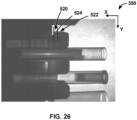
- the method 500 can begin at operation 502 in which a rack reference 520 is identified in a captured image.
- the first hook 160 (also referred to herein as a front tab) of the rack 102 is used as the rack reference 520.
- the first hook 160 can be detected in an image (e.g., the first image 350) captured when the rack 102 is at a first stopping position (e.g., the first image position 330A).
- an edge 522 of the rack 102 ( FIG. 5 ) is predetermined as the rack reference 520.
- the predetermined edge 522 of the rack 102 can be recognized in the first image 350 by the sample container recognition unit 110, as illustrated in FIG. 26 .
- the identified edge 522 of the rack 102 is indicated as a line 524, which is an icon representative of the recognition by the camera unit 202 of the edge 522.
- the X-axis assumes that the rack 102 is fully engaged.
- the sample container recognition unit 110 operates to create one or more regions of interest 528 (also referred to herein as height regions of interest) for container height detection.
- regions of interest 528 also referred to herein as height regions of interest
- three regions of interest 528 are created relative to the rack reference 520, such as by offsetting from the rack reference 520 in the Y-axis.
- a first region of interest 528A is created and arranged to be centered on the rack reference 520 in the Y-axis.
- a second region of interest 528B is created and arranged to be offset from the first region of interest 528A at a predetermined distance (e.g., 200 pixels in FIG. 27 ) in the Y-axis.
- a third region of interest 528C is created and arranged to be offset from the second region of interest 528B at a predetermined distance (e.g., 200 pixels in FIG. 27 ) in the Y-axis.
- the third region of interest 528C can be created by offsetting from the first region of interest 528A.
- the sample container recognition unit 110 For each of the regions of interest 528, the sample container recognition unit 110 operates to detect a top tube edge 530 (e.g., 530A, 530B, and 530C) and determine the height of the associated container 180.
- a top tube edge 530 e.g., 530A, 530B, and 530C
- the height of the container 180 associated with the second region of interest 528B is measured to be 1178.34 pixels
- the height of the container 180 associated with the third region of interest 528C is measured to be 1193.10 pixels.
- a result indicating that no container has been detected can be generated, instead of reporting the height of the container. For example, there is no container in the first region of interest 528A, and thus, the no-container-detection result will be outputted.
- the sample container recognition unit 110 operates to determine the X-coordinate measurement of the rack using the top tube edge 530A in the first region of interest 528A.
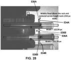
- the sample container recognition unit 110 operates to create one or more regions of interest 534 (also referred to herein as width regions of interest) for container width (or diameter) detection.
- the width regions of interest 534 are created at a preset distance above the rack 102 (in the X-axis) and centered across the height regions of interest 528, respectively.
- the width regions of interest 534 are arranged to transverse the height regions of interest 528, respectively.
- the width (i.e., the Y-axis distance) of each width region of interest 534 can be preset, such as 250-pixel wide in FIG. 28 .
- the sample container recognition unit 110 For each of the width regions of interest 534, the sample container recognition unit 110 operates to detect two opposite sides 536A and 536B of the container and determine the width of the associated container 180.
- the width of the container 180 associated with a region of interest 534A is measured to be 152.99 pixels (i.e., a pixel distance between the opposite sides 536A and 536B), and the width of the container 180 associated with a region of interest 534B is measured to be 151.74 pixels (i.e., a pixel distance between the opposite sides 536A and 536B).
- the sample container recognition unit 110 operates to create one or more regions of interest 540 (also referred to herein as histogram regions of interest) for histogram analysis.
- three histogram regions of interest 540 created relative to the top of each height region, such as by offsetting from the top tube edge 530 in the X-axis.
- the histogram regions of interest 540 are created at a preset distance from the top tube edge 530 in the X-axis (e.g., 5 pixels from the top tube edge 530), while detection of the container has occurred.
- the dimension of each histogram region of interest 540 can be predetermined.
- a histogram value is obtained for each of the histogram regions of interest 540.
- the histogram value of a region of interest 540B associated with the second region of interest 528B is measured to be 177.62
- the histogram value of a region of interest 540C associated with the third region of interest 528C is measured to be 42.53.
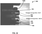
- the histogram analysis at the operation 508 can also detect presence of a cap on the container.
- the measurement of histogram regions of interest 540 can indicate whether a cap is present or not.
- a low histogram value can indicate that a cap is present in that position
- a high histogram value can indicate no cap is present at that position.
- the average histogram value of a region of interest 540D over a cap 542 of the container 180 is measured to be 16.08 (a relatively low value)
- the average histogram value of regions of interest 540E and 540F over the containers 180 without a cap are measured to be 145.81.
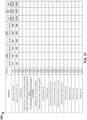
- the sample container recognition unit 110 operates to compare the information obtained at the operations above with a classification table 550 ( FIG. 31 ). For example, for each container, the height value, the width value, and/or the histogram value, can be compared with values in the classification table 550, and a type of the container is determined based on the comparison.
- the classification table 550 is provided to classify different types of containers (the first column) based on the height, width, and histogram values. For each type of container, the height, width, and histogram values can be provided with a minimum value, a maximum value, and an average value.
- the container at issue can be identified as 12x65 or 13x75 mm tube with a cap (the second row of the table 550).
- the same method 500 can be applied to identify the type of the sample cups 184.
- the measurement of histogram regions of interest 540 indicates which types of the cups are present.
- the histogram data may be combined with other measurements such as height and width (diameter) to determine the types of the cups in the cup rack 102B.
- FIG. 33 is a flowchart of a method 600 for adding and verifying a new container in the classification table 550 (i.e., container library, list of approved containers, etc.), which is in accordance with the invention.
- the classification table 550 i.e., container library, list of approved containers, etc.
- the user enters information on a new sample container. This information may include type of container, internal geometry, volume, manufacturer part number, external dimensions, etc.
- the user loads rack with container of interest to be added to the classification table 550 by software (i.e., SW). The user further fills up the container to maximum volume, and loads the rack 102 into the onload lane 124 of the SPU 104.
- the sample analyzer 100 When the user inputs new sample container information (at operation 602), the sample analyzer 100 (e.g., a software application herein) operates to prompt for the user to provide the maximum volume with wash buffer or deionized water, places the new sample container in the rack 102, and loads it on the SPU 104 (at operation 604).
- the information may include information about a manufacturer, a part number, a type of container (e.g., either a tube or a cup), plasma or serum gel matrix in tube, internal container geometry, insert/cup, (i.e., a cup sitting inside of a tube), and/or a volume capacity.
- the SPU (including the sample container recognition unit 110 therein) operates to identify the dimensions of the sample rack and containers therein.
- the information obtained include a height in the rack (e.g., where the pipettor should start level sensing and steps from a home position), a diameter, and a histogram value at the top of each container.
- operation 608 it is determined whether the new sample container is a gel or insert/cup, etc. If operation 608 determines container to be an insert/cup/, etc. then the aliquot pipettor moves to detect the bottom of the container at operation 610. If operation 608 determines the container to be a gel tube, then the aliquot pipettor begins aliquotting from near the top of the liquid in the container.
- the sample analyzer 100 processes the new container and observes the characteristics of the new container as measured by the various detection functions of the sample analyzer 100. For example, to measure volume at step 616, all the fluid from the container is transferred to a sample vessel (i.e., SV), and the sample vessel is transferred to the wash wheel (i.e., WW).
- a sample vessel i.e., SV
- the wash wheel i.e., WW
- the present disclosure can address the user's need of loading mixed types of sample containers into a single rack.
- Different types of racks e.g., a tube rack and a cup rack
- each of different types of racks interfaces with the analyzer in the same way, thereby removing the hassle of sorting sample containers, and eliminating the user error of loading sample containers into wrong sample racks, which could cause QNS (Quantity Not Sufficient) errors.
- QNS Quality Not Sufficient
- the present disclosure also serves as general process monitoring on the sample presentation unit (SPU) to identify the type of container for accurate aspiration of sample, to detect user error of placing the capped sample containers in the sample rack, and also detect user errors associated with placing containers in wrong positions in the sample rack than assigned when ordering tests.
- a container library e.g., a tube library and a cup library. The characteristics determined by the vision system are matched against the libraries to determine which vessel is in each occupied rack position.
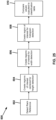
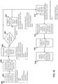
- FIG. 34 illustrates an exemplary architecture of a computing device that can be used to implement aspects of the present disclosure, including the sample analyzer 100 or various systems of the sample analyzer 100, such as the sample container recognition unit 110 and other subunits or subdevices. Further, one or more devices or units included in the systems of the sample analyzer 100 can also be implemented with at least some components of the computing device as illustrated in FIG. 34 .
- a computing device is designated herein as reference numeral 700.
- the computing device 700 is used to execute the operating system, application programs, and software modules (including the software engines) described herein.
- the computing device 700 includes, in some embodiments, at least one processing device 702, such as a central processing unit (CPU).
- processing device 702 such as a central processing unit (CPU).
- CPU central processing unit
- a variety of processing devices are available from a variety of manufacturers, for example, Intel or Advanced Micro Devices.
- the computing device 700 also includes a system memory 704, and a system bus 706 that couples various system components including the system memory 704 to the processing device 702.
- the system bus 706 is one of any number of types of bus structures including a memory bus, or memory controller; a peripheral bus; and a local bus using any of a variety of bus architectures.
- Examples of computing devices suitable for the computing device 700 include a desktop computer, a laptop computer, a tablet computer, a mobile device (such as a smart phone, an iPod ® mobile digital device, or other mobile devices), or other devices configured to process digital instructions.
- a desktop computer such as a laptop computer, a tablet computer
- a mobile device such as a smart phone, an iPod ® mobile digital device, or other mobile devices
- other devices configured to process digital instructions.
- the system memory 704 includes read only memory 708 and random access memory 710.
- the computing device 700 also includes a secondary storage device 714 in some embodiments, such as a hard disk drive, for storing digital data.
- the secondary storage device 714 is connected to the system bus 706 by a secondary storage interface 716.
- the secondary storage devices and their associated computer readable media provide nonvolatile storage of computer readable instructions (including application programs and program modules), data structures, and other data for the computing device 700.
- exemplary environment described herein employs a hard disk drive as a secondary storage device
- other types of computer readable storage media are used in other embodiments. Examples of these other types of computer readable storage media include magnetic cassettes, flash memory cards, digital video disks, Bernoulli cartridges, compact disc read only memories, digital versatile disk read only memories, random access memories, or read only memories. Some embodiments include non-transitory media.
- a number of program modules can be stored in secondary storage device 714 or memory 704, including an operating system 718, one or more application programs 720, other program modules 722, and program data 724.
- computing device 700 includes input devices to enable a user to provide inputs to the computing device 700.
- input devices 726 include a keyboard 728, pointer input device 730, microphone 732, and touch sensitive display 740.
- Other embodiments include other input devices 726.
- the input devices are often connected to the processing device 702 through an input/output interface 738 that is coupled to the system bus 706.
- These input devices 726 can be connected by any number of input/output interfaces, such as a parallel port, serial port, game port, or a universal serial bus.
- Wireless communication between input devices and interface 738 is possible as well, and includes infrared, BLUETOOTH ® wireless technology, WiFi technology (802.11a/b/g/n etc.), cellular, and/or other radio frequency communication systems in some possible embodiments.
- a touch sensitive display device 740 is also connected to the system bus 706 via an interface, such as a video adapter 742.
- the touch sensitive display device 740 includes touch sensors for receiving input from a user when the user touches the display.
- Such sensors can be capacitive sensors, pressure sensors, or other touch sensors.
- the sensors not only detect contact with the display, but also the location of the contact and movement of the contact over time. For example, a user can move a finger or stylus across the screen to provide written inputs. The written inputs are evaluated and, in some embodiments, converted into text inputs.
- the computing device 700 can include various other peripheral devices (not shown), such as speakers or a printer.
- the computing device 700 further includes a communication device 746 configured to establish communication across the network.
- a communication device 746 configured to establish communication across the network.
- the computing device 700 when used in a local area networking environment or a wide area networking environment (such as the Internet), the computing device 700 is typically connected to the network through a network interface, such as a wireless network interface 748.
- a network interface such as a wireless network interface 748.
- Other possible embodiments use other wired and/or wireless communication devices.
- some embodiments of the computing device 700 include an Ethernet network interface, or a modem for communicating across the network.
- the communication device 746 is capable of short-range wireless communication.
- Short-range wireless communication is one-way or two-way short-range to medium-range wireless communication. Short-range wireless communication can be established according to various technologies and protocols. Examples of short-range wireless communication include a radio frequency identification (RFID), a near field communication (NFC), a Bluetooth technology, and a Wi-Fi technology.
- RFID radio frequency identification
- the computing device 700 typically includes at least some form of computer-readable media.
- Computer readable media includes any available media that can be accessed by the computing device 700.
- Computer-readable media include computer readable storage media and computer readable communication media.
- Computer readable storage media includes volatile and nonvolatile, removable and non-removable media implemented in any device configured to store information such as computer readable instructions, data structures, program modules or other data.
- Computer readable storage media includes, but is not limited to, random access memory, read only memory, electrically erasable programmable read only memory, flash memory or other memory technology, compact disc read only memory, digital versatile disks or other optical storage, magnetic cassettes, magnetic tape, magnetic disk storage or other magnetic storage devices, or any other medium that can be used to store the desired information and that can be accessed by the computing device 700.
- Computer readable communication media typically embodies computer readable instructions, data structures, program modules or other data in a modulated data signal such as a carrier wave or other transport mechanism and includes any information delivery media.
- modulated data signal refers to a signal that has one or more of its characteristics set or changed in such a manner as to encode information in the signal.
- computer readable communication media includes wired media such as a wired network or direct-wired connection, and wireless media such as acoustic, radio frequency, infrared, and other wireless media. Combinations of any of the above are also included within the scope of computer readable media.
Landscapes
- Engineering & Computer Science (AREA)
- Physics & Mathematics (AREA)
- General Physics & Mathematics (AREA)
- Theoretical Computer Science (AREA)
- Multimedia (AREA)
- Computer Vision & Pattern Recognition (AREA)
- General Health & Medical Sciences (AREA)
- Health & Medical Sciences (AREA)
- Life Sciences & Earth Sciences (AREA)
- Pathology (AREA)
- Immunology (AREA)
- Biochemistry (AREA)
- Analytical Chemistry (AREA)
- Chemical & Material Sciences (AREA)
- Artificial Intelligence (AREA)
- Evolutionary Computation (AREA)
- Software Systems (AREA)
- Medical Informatics (AREA)
- Databases & Information Systems (AREA)
- Computing Systems (AREA)
- Toxicology (AREA)
- Electromagnetism (AREA)
- Geometry (AREA)
- Automatic Analysis And Handling Materials Therefor (AREA)
Claims (15)
- Verfahren zum Bestimmen eines Behältertyps (180, 182, 184) in einem Gestell (102, 102A, 102B) in einem automatischen Analysegerät (100), das eine Probenpräsentationseinheit (104) umfasst, das Verfahren umfassend:Erfassen mindestens eines Bildes (340, 350, 352, 354, 356) von mindestens einem Abschnitt des Behälters (180, 182, 184) und mindestens einem Abschnitt des Gestells (102, 102A, 102B) unter Verwendung einer Bilderfassungsvorrichtung (110), wobei der Behälter (180, 182, 184) von dem Gestell (102, 102A, 102B) gehalten wird;Finden eines Referenzmerkmals (520, 522) auf dem Gestell (102, 102A, 102B) als erstes Bildmerkmal in dem mindestens einen Bild (340, 350, 352, 354, 356);zumindest teilweise Definieren eines ersten Suchbereichs (528) in dem mindestens einen Bild (340, 350, 352, 354, 356) auf der Grundlage einer ersten relativen Position zu dem ersten Bildmerkmal in dem mindestens einen Bild (340, 350, 352, 354, 356);Finden, im ersten Suchbereich (528) in mindestens einem Bild (340, 350, 352, 354, 356) eines ersten Merkmals (530, 530A, 530B, 530C, 536A, 536B) auf dem Behälter (180, 182, 184) als zweites Bildmerkmal in dem mindestens einen Bild (340, 350, 352, 354, 356);Berechnen eines ersten geometrischen Merkmals des Behälters (180, 182, 184) auf der Grundlage einer Position des zweiten Bildmerkmals in dem mindestens einen Bild (340, 350, 352, 354, 356); undBestimmen des Behältertyps (180, 182, 184) durch Nachschlagen des ersten geometrischen Merkmals des Behälters (180, 182, 184) in einer Tabelle (550);wobei das Gestell (102, 102A, 102B) eine Vielzahl von Behältern hält und wobei Typen von zusätzlichen Behältern der Vielzahl von Behältern durch Nachschlagen geometrischer Eigenschaften der zusätzlichen Behälter in der Tabelle (550) bestimmt werden;gekennzeichnet durch das Verfahren weiter umfassend:Hinzufügen und Verifizieren eines neuen Behältertyps (180, 182, 184) zur Tabelle (550);Eingeben von Informationen über den neuen Behältertyp (180, 182, 184);Befüllen des neuen Behältertyps (180, 182, 184) mit einem Waschpuffer oder deionisiertem Wasser;Beladen des Gestells (102, 102A, 102B) mit dem neuen Behältertyp (180, 182, 184);Beladen des Gestells (102, 102A, 102B) mit dem neuen Behältertyp (180, 182, 184) in einer Lade-Spur (124) der Probenpräsentationseinheit (104) des automatischen Analysegeräts (100); undErmitteln der Abmessungen des Gestells (102, 102A, 102B) und der darin befindlichen Behälter mit der Bilderfassungsvorrichtung (110).
- Verfahren nach Anspruch 1, wobei das Referenzmerkmal eine Kante des Gestells (102, 102A, 102B) ist.
- Verfahren nach Anspruch 1 oder 2, wobei das erste Bildmerkmal in dem mindestens einen Bild (340, 350, 352, 354, 356) versetzt und von dem ersten Suchbereich in dem mindestens einen Bild (340, 350, 352, 354, 356) um die erste relative Position beabstandet ist.
- Verfahren nach einem der Ansprüche 1-3, wobei die erste relative Position vorbestimmt ist.
- Verfahren nach einem der Ansprüche 1-4, weiter umfassend:zumindest teilweise Definieren eines zweiten Suchbereichs in dem mindestens einen Bild (340, 350, 352, 354, 356) basierend auf einer zweiten relativen Position zu dem ersten Bildmerkmal in dem Bild;Finden, im zweiten Suchbereich in mindestens einem Bild (340, 350, 352, 354, 356), eines zweiten Merkmals auf dem Behälter (180, 182, 184) als drittes Bildmerkmal in mindestens einem Bild (340, 350, 352, 354, 356);Finden, im zweiten Suchbereich in mindestens einem Bild (340, 350, 352, 354, 356), eines dritten Merkmals auf dem Behälter (180, 182, 184) als viertes Bildmerkmal in mindestens einem Bild (340, 350, 352, 354, 356);Berechnen eines zweiten geometrischen Merkmals des Behälters (180, 182, 184) auf der Grundlage eines Abstands zwischen dem dritten Bildmerkmal und dem vierten Bildmerkmal in dem mindestens einen Bild (340, 350, 352, 354, 356); undweiteres Bestimmen des Behältertyps (180, 182, 184) durch Nachschlagen des zweiten geometrischen Merkmals des Behälters (180, 182, 184) in der Tabelle (550).
- Verfahren nach einem der Ansprüche 1-5, wobei die erste geometrische Eigenschaft des Behälters (180, 182, 184) eine längs verlaufende Eigenschaft des Behälters (180, 182, 184) ist.
- Verfahren nach einem der Ansprüche 1-6, wobei das erste geometrische Merkmal des Behälters (180, 182, 184) eine Länge des Behälters (180, 182, 184) angibt.
- Verfahren nach einem der Ansprüche 1-7, wobei die zweite geometrische Eigenschaft des Behälters (180, 182, 184) einen Außendurchmesser des Behälters (180, 182, 184) angibt.
- Verfahren nach einem der Ansprüche 1-8, wobei das mindestens eine Bild (340, 350, 352, 354, 356) nur ein einziges Bild einschließt.
- Verfahren nach einem der Ansprüche 1-9, wobei das mindestens eine Bild (340, 350, 352, 354, 356) eine Vielzahl von Bildern einschließt, die an einer Vielzahl von Gestellpositionen (332, 332A, 332B, 332C) aufgenommen wurden.
- Verfahren nach einem der Ansprüche 1-10, weiter umfassend Bestimmen einer Identität des Behälters (180, 182, 184) in dem Gestell (102, 102A, 102B), das Verfahren weiter umfassend:Aufnehmen von mindestens einem Bild mit hoher Belichtung (340) von mindestens einem Teil des Behälters (180, 182, 184) und mindestens einem Teil des Gestells (102, 102A, 102B) mit der Bilderfassungsvorrichtung;Lesen einer Codemarkierung (186) von mindestens einem Bild mit hoher Belichtung und dadurch Bestimmen der Identität des Behälters (180, 182, 184) im Gestell (102, 102A, 102B); undwobei das mindestens eine Bild (340, 350, 352, 354, 356) mindestens ein Bild (350, 352, 354) mit geringer Belichtung von mindestens dem Abschnitt des Behälters (180, 182, 184) und mindestens dem Abschnitt des Gestells (102, 102A, 102B) ist.
- Verfahren nach Anspruch 11, wobei die Codemarkierung ein Strichcode (186) ist.
- Verfahren nach einem der Ansprüche 5-12, weiter umfassend Bestimmen, ob sich eine Kappe (542) auf dem Behälter (180, 182, 184) in dem Gestell (102, 102A, 102B) befindet, das Verfahren weiter umfassend:Definieren eines Histogrammbereichs basierend auf der zweiten relativen Position des zweiten Bildmerkmals in dem mindestens einen Bild (340, 350, 352, 354, 356); undExtrahieren von Histogramm-Informationen aus dem Histogramm-Bereich und dabei Bestimmen, ob der Deckel auf dem Behälter (180, 182, 184) sitzt.
- Verfahren nach Anspruch 13, wobei die Fläche des Histogramms innerhalb des Suchbereichs liegt.
- Verfahren nach einem der Ansprüche 1-14, weiter umfassend:Verarbeiten des neuen Behältertyps (180, 182, 184) und Beobachten der Eigenschaften des neuen Behältertyps (180, 182, 184), wie sie durch verschiedene Erkennungsfunktionen des automatischen Analysegeräts (100) gemessen werden; und/oderBestimmen, ob es sich bei dem neuen Behältertyp (180, 182, 184) um ein Gelröhrchen handelt oder
einen Einsatz oder Becher;wobei, wenn der neue Behältertyp (180, 182, 184) als Einsatz oder Becher bestimmt wird, der Aliquot-Pipettierer bewegt wird, um den Boden des Behälters zu erfassen; undwobei, wenn der neue Behältertyp (180, 182, 184) als Gelröhrchen bestimmt wird, der Aliquot-Pipettierer mit dem Aliquotieren nahe der Oberseite der Flüssigkeit im neuen Behältertyp (180, 182, 184) beginnt.
Applications Claiming Priority (2)
| Application Number | Priority Date | Filing Date | Title |
|---|---|---|---|
| US201762578236P | 2017-10-27 | 2017-10-27 | |
| PCT/US2018/057810 WO2019084468A1 (en) | 2017-10-27 | 2018-10-26 | RECOGNITION OF SAMPLE CONTAINER |
Publications (2)
| Publication Number | Publication Date |
|---|---|
| EP3701271A1 EP3701271A1 (de) | 2020-09-02 |
| EP3701271B1 true EP3701271B1 (de) | 2025-05-21 |
Family
ID=64453579
Family Applications (1)
| Application Number | Title | Priority Date | Filing Date |
|---|---|---|---|
| EP18807762.2A Active EP3701271B1 (de) | 2017-10-27 | 2018-10-26 | Probenbehältererkennung |
Country Status (4)
| Country | Link |
|---|---|
| US (1) | US11574460B2 (de) |
| EP (1) | EP3701271B1 (de) |
| CN (1) | CN111512162B (de) |
| WO (1) | WO2019084468A1 (de) |
Families Citing this family (28)
| Publication number | Priority date | Publication date | Assignee | Title |
|---|---|---|---|---|
| US20150112230A1 (en) | 2011-11-28 | 2015-04-23 | Remendium Labs Llc | Treatment of male urinary incontinence and sexual dysfunction |
| US20150112231A1 (en) | 2011-11-28 | 2015-04-23 | Remendium Labs Llc | Treatment of fecal incontinence |
| CA2936061A1 (en) | 2014-01-06 | 2015-07-09 | Remendium Labs Llc | System and method for kegel training |
| JP7242524B2 (ja) | 2016-07-29 | 2023-03-20 | レノビア インコーポレイテッド | 骨盤底筋をトレーニングするためのデバイス、システムおよび方法 |
| BR112019008270A8 (pt) * | 2016-10-28 | 2023-04-11 | Beckman Coulter Inc | Sistema de avaliação de preparação de substância |
| BR112020008231A2 (pt) | 2017-10-27 | 2020-10-27 | Renovia, Inc. | dispositivos, sistemas e métodos para treinamento dos músculos do assoalho pélvico |
| EP3701271B1 (de) * | 2017-10-27 | 2025-05-21 | Beckman Coulter, Inc. | Probenbehältererkennung |
| EP3773210A4 (de) | 2018-04-13 | 2022-06-01 | Renovia Inc. | Vorrichtungen, systeme und verfahren zum trainieren der beckenbodenmuskeln |
| US12502542B2 (en) | 2018-04-27 | 2025-12-23 | Axena Health, Inc. | Devices, systems, and methods for treating urinary and fecal incontinence |
| JP6886952B2 (ja) * | 2018-09-28 | 2021-06-16 | シスメックス株式会社 | 検体測定装置および検体測定方法 |
| US11941478B2 (en) | 2018-10-19 | 2024-03-26 | Diagnostics Instruments, Inc. | Barcode scanning of bulk sample containers |
| CA3118295A1 (en) | 2018-10-30 | 2020-05-07 | Renovia Inc. | Devices, systems, and methods for monitoring bladder function |
| USD888948S1 (en) | 2019-04-02 | 2020-06-30 | Renovia Inc. | Intravaginal device |
| USD898911S1 (en) | 2019-04-03 | 2020-10-13 | Renovia Inc. | Intravaginal device assembly |
| USD889649S1 (en) | 2019-04-05 | 2020-07-07 | Renovia Inc. | Intravaginal device |
| USD896958S1 (en) | 2019-04-11 | 2020-09-22 | Renovia Inc. | Intravaginal device |
| USD899593S1 (en) | 2019-04-12 | 2020-10-20 | Renovia Inc. | Intravaginal device |
| USD897530S1 (en) | 2019-04-23 | 2020-09-29 | Renovia Inc. | Intravaginal device |
| USD896959S1 (en) | 2019-04-23 | 2020-09-22 | Renovia Inc. | Intravaginal device |
| USD922575S1 (en) | 2019-10-25 | 2021-06-15 | Renovia Inc. | Intravaginal device |
| JP7023450B2 (ja) * | 2019-12-12 | 2022-02-22 | 株式会社Mujin | カメラによって生成される画像情報に基づいて、動作計画を実行する方法および計算システム |
| EP4119952B1 (de) * | 2020-03-11 | 2025-07-09 | Hitachi High-Tech Corporation | Automatische analysevorrichtung |
| EP3968027A1 (de) * | 2020-09-14 | 2022-03-16 | Eppendorf AG | Verfahren und vorrichtung zur identifizierung von laborgeräten |
| EP3979131B1 (de) | 2020-10-02 | 2026-03-04 | Roche Diagnostics GmbH | Verfahren zur bestimmung mindestens eines zustandes mindestens eines hohlraums einer transportschnittstelle mit konfiguration zum transport von probenröhrchen |
| US20240426851A1 (en) * | 2021-03-04 | 2024-12-26 | Hitachi High-Tech Corporation | Automatic Analyzer and Sample Dispensing Method |
| EP4113362A1 (de) * | 2021-07-01 | 2023-01-04 | Diagnostic Instruments, Inc. | Strichcodeabtastung von sammelprobenbehältern |
| EP4466681A1 (de) | 2021-11-22 | 2024-11-27 | F. Hoffmann-La Roche SA | Verfahren und system zum betreiben eines laborautomatisierungssystems |
| WO2024034220A1 (ja) * | 2022-08-10 | 2024-02-15 | 株式会社日立ハイテク | 自動分析装置 |
Family Cites Families (10)
| Publication number | Priority date | Publication date | Assignee | Title |
|---|---|---|---|---|
| AUPP058197A0 (en) * | 1997-11-27 | 1997-12-18 | A.I. Scientific Pty Ltd | Pathology sample tube distributor |
| US8170271B2 (en) * | 2008-06-25 | 2012-05-01 | Jadak Llc | System and method for test tube and cap identification |
| JP5859439B2 (ja) * | 2009-08-13 | 2016-02-10 | シーメンス・ヘルスケア・ダイアグノスティックス・インコーポレイテッド | 臨床分析機によって分析される液体サンプルおよび容器の中の干渉物質および物理的寸法を確定するための方法ならびに装置 |
| JP5274436B2 (ja) * | 2009-11-26 | 2013-08-28 | ベックマン コールター, インコーポレイテッド | 自動分析装置 |
| EP2434291B1 (de) * | 2010-09-23 | 2016-12-07 | Hach Lange GmbH | Verfahren zur automatisierten Bestimmung eines Analyts |
| CA2950296C (en) * | 2014-06-10 | 2022-12-13 | Siemens Healthcare Diagnostics Inc. | Drawer vision system |
| JP6492681B2 (ja) * | 2015-01-20 | 2019-04-03 | 富士通セミコンダクター株式会社 | 半導体装置とその製造方法 |
| JP2018096740A (ja) * | 2016-12-09 | 2018-06-21 | 株式会社日立ハイテクノロジーズ | 生体試料分析装置 |
| EP3701271B1 (de) * | 2017-10-27 | 2025-05-21 | Beckman Coulter, Inc. | Probenbehältererkennung |
| US11250944B2 (en) * | 2019-01-02 | 2022-02-15 | Healthy.Io Ltd. | Uniquely coded color boards for analyzing images |
-
2018
- 2018-10-26 EP EP18807762.2A patent/EP3701271B1/de active Active
- 2018-10-26 US US16/757,924 patent/US11574460B2/en active Active
- 2018-10-26 CN CN201880083121.3A patent/CN111512162B/zh active Active
- 2018-10-26 WO PCT/US2018/057810 patent/WO2019084468A1/en not_active Ceased
Also Published As
| Publication number | Publication date |
|---|---|
| EP3701271A1 (de) | 2020-09-02 |
| CN111512162B (zh) | 2025-03-07 |
| US11574460B2 (en) | 2023-02-07 |
| WO2019084468A1 (en) | 2019-05-02 |
| US20200372287A1 (en) | 2020-11-26 |
| CN111512162A (zh) | 2020-08-07 |
Similar Documents
| Publication | Publication Date | Title |
|---|---|---|
| EP3701271B1 (de) | Probenbehältererkennung | |
| CN114041060B (zh) | 基于样本和/或样本容器识别的定制的样本处理 | |
| JP7611873B2 (ja) | 物質調製評価システム | |
| US11630115B2 (en) | Sample testing system with automated control of sample retesting | |
| US10145858B2 (en) | Automatic analyzing apparatus | |
| US9377383B2 (en) | Specimen processing apparatus | |
| US20210318349A1 (en) | Test tube rack dispatching method, analysis system and test tube rack | |
| US20110271773A1 (en) | Automatic analysis apparatus and automatic analysis method | |
| CN116603774A (zh) | 实验室系统 | |
| US9671419B2 (en) | Liquid collection device and automated analyzer provided therewith | |
| KR20170077821A (ko) | 검체 처리 장치 및 검체 처리 방법 | |
| US8641988B2 (en) | Sample analyzer and sample analysis system | |
| FR2905493A1 (fr) | Systeme automatise de realisation d'inventaires localises | |
| JP6210891B2 (ja) | 自動分析装置 | |
| JP2015141024A5 (de) | ||
| JP7414953B2 (ja) | 自動分析装置 | |
| JP7561267B2 (ja) | 自動分析装置 | |
| JPH0277651A (ja) | 自動化学分析装置 | |
| EP4692803A1 (de) | Automatische analysevorrichtung | |
| US12222357B2 (en) | Automatic analyzer |
Legal Events
| Date | Code | Title | Description |
|---|---|---|---|
| STAA | Information on the status of an ep patent application or granted ep patent |
Free format text: STATUS: UNKNOWN |
|
| STAA | Information on the status of an ep patent application or granted ep patent |
Free format text: STATUS: THE INTERNATIONAL PUBLICATION HAS BEEN MADE |
|
| PUAI | Public reference made under article 153(3) epc to a published international application that has entered the european phase |
Free format text: ORIGINAL CODE: 0009012 |
|
| STAA | Information on the status of an ep patent application or granted ep patent |
Free format text: STATUS: REQUEST FOR EXAMINATION WAS MADE |
|
| 17P | Request for examination filed |
Effective date: 20200507 |
|
| AK | Designated contracting states |
Kind code of ref document: A1 Designated state(s): AL AT BE BG CH CY CZ DE DK EE ES FI FR GB GR HR HU IE IS IT LI LT LU LV MC MK MT NL NO PL PT RO RS SE SI SK SM TR |
|
| AX | Request for extension of the european patent |
Extension state: BA ME |
|
| DAV | Request for validation of the european patent (deleted) | ||
| DAX | Request for extension of the european patent (deleted) | ||
| STAA | Information on the status of an ep patent application or granted ep patent |
Free format text: STATUS: EXAMINATION IS IN PROGRESS |
|
| 17Q | First examination report despatched |
Effective date: 20221012 |
|
| P01 | Opt-out of the competence of the unified patent court (upc) registered |
Effective date: 20230529 |
|
| GRAP | Despatch of communication of intention to grant a patent |
Free format text: ORIGINAL CODE: EPIDOSNIGR1 |
|
| STAA | Information on the status of an ep patent application or granted ep patent |
Free format text: STATUS: GRANT OF PATENT IS INTENDED |
|
| RIC1 | Information provided on ipc code assigned before grant |
Ipc: G06V 10/20 20220101ALI20250131BHEP Ipc: G06V 10/75 20220101ALI20250131BHEP Ipc: G06V 10/50 20220101ALI20250131BHEP Ipc: G06V 10/44 20220101ALI20250131BHEP Ipc: G01N 35/04 20060101ALI20250131BHEP Ipc: G01N 35/00 20060101AFI20250131BHEP |
|
| INTG | Intention to grant announced |
Effective date: 20250226 |
|
| GRAS | Grant fee paid |
Free format text: ORIGINAL CODE: EPIDOSNIGR3 |
|
| GRAA | (expected) grant |
Free format text: ORIGINAL CODE: 0009210 |
|
| STAA | Information on the status of an ep patent application or granted ep patent |
Free format text: STATUS: THE PATENT HAS BEEN GRANTED |
|
| AK | Designated contracting states |
Kind code of ref document: B1 Designated state(s): AL AT BE BG CH CY CZ DE DK EE ES FI FR GB GR HR HU IE IS IT LI LT LU LV MC MK MT NL NO PL PT RO RS SE SI SK SM TR |
|
| REG | Reference to a national code |
Ref country code: GB Ref legal event code: FG4D |
|
| REG | Reference to a national code |
Ref country code: CH Ref legal event code: EP |
|
| REG | Reference to a national code |
Ref country code: DE Ref legal event code: R096 Ref document number: 602018082136 Country of ref document: DE |
|
| REG | Reference to a national code |
Ref country code: IE Ref legal event code: FG4D |
|
| REG | Reference to a national code |
Ref country code: NL Ref legal event code: MP Effective date: 20250521 |
|
| PG25 | Lapsed in a contracting state [announced via postgrant information from national office to epo] |
Ref country code: PT Free format text: LAPSE BECAUSE OF FAILURE TO SUBMIT A TRANSLATION OF THE DESCRIPTION OR TO PAY THE FEE WITHIN THE PRESCRIBED TIME-LIMIT Effective date: 20250922 Ref country code: ES Free format text: LAPSE BECAUSE OF FAILURE TO SUBMIT A TRANSLATION OF THE DESCRIPTION OR TO PAY THE FEE WITHIN THE PRESCRIBED TIME-LIMIT Effective date: 20250521 Ref country code: FI Free format text: LAPSE BECAUSE OF FAILURE TO SUBMIT A TRANSLATION OF THE DESCRIPTION OR TO PAY THE FEE WITHIN THE PRESCRIBED TIME-LIMIT Effective date: 20250521 |
|
| REG | Reference to a national code |
Ref country code: LT Ref legal event code: MG9D |
|
| PG25 | Lapsed in a contracting state [announced via postgrant information from national office to epo] |
Ref country code: NO Free format text: LAPSE BECAUSE OF FAILURE TO SUBMIT A TRANSLATION OF THE DESCRIPTION OR TO PAY THE FEE WITHIN THE PRESCRIBED TIME-LIMIT Effective date: 20250821 Ref country code: GR Free format text: LAPSE BECAUSE OF FAILURE TO SUBMIT A TRANSLATION OF THE DESCRIPTION OR TO PAY THE FEE WITHIN THE PRESCRIBED TIME-LIMIT Effective date: 20250822 |
|
| PG25 | Lapsed in a contracting state [announced via postgrant information from national office to epo] |
Ref country code: NL Free format text: LAPSE BECAUSE OF FAILURE TO SUBMIT A TRANSLATION OF THE DESCRIPTION OR TO PAY THE FEE WITHIN THE PRESCRIBED TIME-LIMIT Effective date: 20250521 Ref country code: PL Free format text: LAPSE BECAUSE OF FAILURE TO SUBMIT A TRANSLATION OF THE DESCRIPTION OR TO PAY THE FEE WITHIN THE PRESCRIBED TIME-LIMIT Effective date: 20250521 |
|
| PG25 | Lapsed in a contracting state [announced via postgrant information from national office to epo] |
Ref country code: BG Free format text: LAPSE BECAUSE OF FAILURE TO SUBMIT A TRANSLATION OF THE DESCRIPTION OR TO PAY THE FEE WITHIN THE PRESCRIBED TIME-LIMIT Effective date: 20250521 |
|
| PG25 | Lapsed in a contracting state [announced via postgrant information from national office to epo] |
Ref country code: HR Free format text: LAPSE BECAUSE OF FAILURE TO SUBMIT A TRANSLATION OF THE DESCRIPTION OR TO PAY THE FEE WITHIN THE PRESCRIBED TIME-LIMIT Effective date: 20250521 |
|
| PG25 | Lapsed in a contracting state [announced via postgrant information from national office to epo] |
Ref country code: RS Free format text: LAPSE BECAUSE OF FAILURE TO SUBMIT A TRANSLATION OF THE DESCRIPTION OR TO PAY THE FEE WITHIN THE PRESCRIBED TIME-LIMIT Effective date: 20250821 |
|
| PG25 | Lapsed in a contracting state [announced via postgrant information from national office to epo] |
Ref country code: IS Free format text: LAPSE BECAUSE OF FAILURE TO SUBMIT A TRANSLATION OF THE DESCRIPTION OR TO PAY THE FEE WITHIN THE PRESCRIBED TIME-LIMIT Effective date: 20250921 |
|
| PG25 | Lapsed in a contracting state [announced via postgrant information from national office to epo] |
Ref country code: LV Free format text: LAPSE BECAUSE OF FAILURE TO SUBMIT A TRANSLATION OF THE DESCRIPTION OR TO PAY THE FEE WITHIN THE PRESCRIBED TIME-LIMIT Effective date: 20250521 |
|
| REG | Reference to a national code |
Ref country code: AT Ref legal event code: MK05 Ref document number: 1797156 Country of ref document: AT Kind code of ref document: T Effective date: 20250521 |
|
| PGFP | Annual fee paid to national office [announced via postgrant information from national office to epo] |
Ref country code: DE Payment date: 20251028 Year of fee payment: 8 |
|
| PGFP | Annual fee paid to national office [announced via postgrant information from national office to epo] |
Ref country code: GB Payment date: 20251023 Year of fee payment: 8 |
|
| PG25 | Lapsed in a contracting state [announced via postgrant information from national office to epo] |
Ref country code: DK Free format text: LAPSE BECAUSE OF FAILURE TO SUBMIT A TRANSLATION OF THE DESCRIPTION OR TO PAY THE FEE WITHIN THE PRESCRIBED TIME-LIMIT Effective date: 20250521 Ref country code: AT Free format text: LAPSE BECAUSE OF FAILURE TO SUBMIT A TRANSLATION OF THE DESCRIPTION OR TO PAY THE FEE WITHIN THE PRESCRIBED TIME-LIMIT Effective date: 20250521 Ref country code: SM Free format text: LAPSE BECAUSE OF FAILURE TO SUBMIT A TRANSLATION OF THE DESCRIPTION OR TO PAY THE FEE WITHIN THE PRESCRIBED TIME-LIMIT Effective date: 20250521 |
|
| PGFP | Annual fee paid to national office [announced via postgrant information from national office to epo] |
Ref country code: FR Payment date: 20251027 Year of fee payment: 8 |
|
| PG25 | Lapsed in a contracting state [announced via postgrant information from national office to epo] |
Ref country code: CZ Free format text: LAPSE BECAUSE OF FAILURE TO SUBMIT A TRANSLATION OF THE DESCRIPTION OR TO PAY THE FEE WITHIN THE PRESCRIBED TIME-LIMIT Effective date: 20250521 |
|
| PG25 | Lapsed in a contracting state [announced via postgrant information from national office to epo] |
Ref country code: EE Free format text: LAPSE BECAUSE OF FAILURE TO SUBMIT A TRANSLATION OF THE DESCRIPTION OR TO PAY THE FEE WITHIN THE PRESCRIBED TIME-LIMIT Effective date: 20250521 |
|
| PG25 | Lapsed in a contracting state [announced via postgrant information from national office to epo] |
Ref country code: SK Free format text: LAPSE BECAUSE OF FAILURE TO SUBMIT A TRANSLATION OF THE DESCRIPTION OR TO PAY THE FEE WITHIN THE PRESCRIBED TIME-LIMIT Effective date: 20250521 Ref country code: RO Free format text: LAPSE BECAUSE OF FAILURE TO SUBMIT A TRANSLATION OF THE DESCRIPTION OR TO PAY THE FEE WITHIN THE PRESCRIBED TIME-LIMIT Effective date: 20250521 |
|
| PG25 | Lapsed in a contracting state [announced via postgrant information from national office to epo] |
Ref country code: IT Free format text: LAPSE BECAUSE OF FAILURE TO SUBMIT A TRANSLATION OF THE DESCRIPTION OR TO PAY THE FEE WITHIN THE PRESCRIBED TIME-LIMIT Effective date: 20250521 |