EP3701150B1 - Interner abgaskanal für kompressor - Google Patents
Interner abgaskanal für kompressor Download PDFInfo
- Publication number
- EP3701150B1 EP3701150B1 EP18800412.1A EP18800412A EP3701150B1 EP 3701150 B1 EP3701150 B1 EP 3701150B1 EP 18800412 A EP18800412 A EP 18800412A EP 3701150 B1 EP3701150 B1 EP 3701150B1
- Authority
- EP
- European Patent Office
- Prior art keywords
- bearing housing
- rotor
- recess
- casing
- compressor casing
- Prior art date
- Legal status (The legal status is an assumption and is not a legal conclusion. Google has not performed a legal analysis and makes no representation as to the accuracy of the status listed.)
- Active
Links
Images


Classifications
-
- F—MECHANICAL ENGINEERING; LIGHTING; HEATING; WEAPONS; BLASTING
- F04—POSITIVE - DISPLACEMENT MACHINES FOR LIQUIDS; PUMPS FOR LIQUIDS OR ELASTIC FLUIDS
- F04C—ROTARY-PISTON, OR OSCILLATING-PISTON, POSITIVE-DISPLACEMENT MACHINES FOR LIQUIDS; ROTARY-PISTON, OR OSCILLATING-PISTON, POSITIVE-DISPLACEMENT PUMPS
- F04C18/00—Rotary-piston pumps specially adapted for elastic fluids
- F04C18/08—Rotary-piston pumps specially adapted for elastic fluids of intermeshing-engagement type, i.e. with engagement of co-operating members similar to that of toothed gearing
- F04C18/12—Rotary-piston pumps specially adapted for elastic fluids of intermeshing-engagement type, i.e. with engagement of co-operating members similar to that of toothed gearing of other than internal-axis type
- F04C18/14—Rotary-piston pumps specially adapted for elastic fluids of intermeshing-engagement type, i.e. with engagement of co-operating members similar to that of toothed gearing of other than internal-axis type with toothed rotary pistons
- F04C18/16—Rotary-piston pumps specially adapted for elastic fluids of intermeshing-engagement type, i.e. with engagement of co-operating members similar to that of toothed gearing of other than internal-axis type with toothed rotary pistons with helical teeth, e.g. chevron-shaped, screw type
-
- F—MECHANICAL ENGINEERING; LIGHTING; HEATING; WEAPONS; BLASTING
- F04—POSITIVE - DISPLACEMENT MACHINES FOR LIQUIDS; PUMPS FOR LIQUIDS OR ELASTIC FLUIDS
- F04C—ROTARY-PISTON, OR OSCILLATING-PISTON, POSITIVE-DISPLACEMENT MACHINES FOR LIQUIDS; ROTARY-PISTON, OR OSCILLATING-PISTON, POSITIVE-DISPLACEMENT PUMPS
- F04C29/00—Component parts, details or accessories of pumps or pumping installations, not provided for in groups F04C18/00 - F04C28/00
- F04C29/12—Arrangements for admission or discharge of the working fluid, e.g. constructional features of the inlet or outlet
-
- F—MECHANICAL ENGINEERING; LIGHTING; HEATING; WEAPONS; BLASTING
- F04—POSITIVE - DISPLACEMENT MACHINES FOR LIQUIDS; PUMPS FOR LIQUIDS OR ELASTIC FLUIDS
- F04C—ROTARY-PISTON, OR OSCILLATING-PISTON, POSITIVE-DISPLACEMENT MACHINES FOR LIQUIDS; ROTARY-PISTON, OR OSCILLATING-PISTON, POSITIVE-DISPLACEMENT PUMPS
- F04C2210/00—Fluid
- F04C2210/22—Fluid gaseous, i.e. compressible
-
- F—MECHANICAL ENGINEERING; LIGHTING; HEATING; WEAPONS; BLASTING
- F04—POSITIVE - DISPLACEMENT MACHINES FOR LIQUIDS; PUMPS FOR LIQUIDS OR ELASTIC FLUIDS
- F04C—ROTARY-PISTON, OR OSCILLATING-PISTON, POSITIVE-DISPLACEMENT MACHINES FOR LIQUIDS; ROTARY-PISTON, OR OSCILLATING-PISTON, POSITIVE-DISPLACEMENT PUMPS
- F04C29/00—Component parts, details or accessories of pumps or pumping installations, not provided for in groups F04C18/00 - F04C28/00
- F04C29/06—Silencing
- F04C29/068—Silencing the silencing means being arranged inside the pump housing
Definitions
- the subject matter disclosed herein relates generally to fluid machines, and more specifically, to fluid machines, such as compressors, having helically lobed rotors.
- Non-flammable, low GWP refrigerants are replacing existing refrigerants in many applications, but have lower density and do not possess the same cooling capacity as existing refrigerants.
- Replacement refrigerants require a compressor capable of providing a significantly greater displacement, such as a screw compressor.
- WO 2010/008457 A2 relates to screw compressors with means for varying volume ratio.
- US 4609329 A discloses a variable volume ratio screw compressor having a side load inlet port for the injection of refrigerant vapor into the interlobe volume.
- US 2012/039737 A1 discloses a screw compressor having an overpressure outlet and overpressure valve provided in a side wall of a casing of the compressor.
- EP 0828079 A2 relates to a casing structure for a Lysholm compressor which is adapted to accommodate intermeshing male and female rotors.
- US 2004/041280 A1 discloses an air supply system for a fuel cell, comprising an air supply mechanism adapted to supply air to a fuel cell and a liquefaction unit acting as a water supply mechanism for separating water from exhaust gas discharged from the fuel cell and supplying that water to the air supply mechanism.
- a compressor casing having an internal gas passage includes a first bearing housing arranged at a first end of the casing, a second bearing housing arranged at a second, opposite end of the casing, and a rotor case disposed between the first bearing housing and the second bearing housing.
- the rotor case includes an axially extending bore within which a plurality of rotors is receivable and a hollow internal cavity separate from the bore.
- the hollow internal cavity is fluidly coupled to the bore via at least one recess.
- At least one exit opening is formed in the second bearing housing.
- the at least one exit opening is operably coupled to the hollow internal cavity of the rotor case.
- the second bearing housing comprises an internal chamber arranged in fluid communication with the hollow internal cavity of the rotor case, and the second bearing housing comprises a fluid passageway extending between the hollow internal cavity and the internal chamber.
- At least one of the first bearing housing and the second bearing housing may include the at least one recess fluidly coupling the bore to the hollow internal cavity.
- the first bearing housing may include a first recess and the second bearing housing may include a second recess.
- the at least one recess may be formed in the rotor case.
- the at least one exit opening may include a plurality of exit openings.
- Each of the plurality of exit openings may have a substantially identical configuration.
- the plurality of exit openings may be distributed about a periphery of the second bearing housing.
- the plurality of exit openings may be arranged about the second bearing housing such that compressed refrigerant output from the plurality of exit openings is uniformly distributed.
- the at least one exit opening may include a plurality of exit openings and the internal chamber distributes compressed refrigerant from the hollow internal cavity to each of the plurality of exit openings.
- the fluid machine 20 is an opposed screw compressor. However, other suitable types of a fluid machine, such as a pump, fluid motor, or engine for example, are also within the scope of the disclosure.
- the fluid machine 20 includes a first rotor 22 intermeshed with a second rotor 24.
- the first rotor 22 may be a male rotor having a male-lobed working portion 26 and the second rotor 24 may be a female rotor including a female-lobed portion 28.
- the first rotor 22 may be a female rotor and the second rotor 24 may be a male rotor.
- the working portion 26 of the first rotor 22 includes at least one first helical lobe 30 and at least one second helical lobe 32.
- the first rotor 22 may include two separate portions defining the first helical lobes 30 and the second helical lobes 32.
- the first rotor 22, including the first and second helical lobes 30, 32, may be formed as a single integral piece.
- the fluid machine 20 includes a first shaft 34 fixed for rotation with the first rotor 22.
- the fluid machine 20 further include a casing 36 rotatably supporting the first shaft 34 and at least partially enclosing the first rotor 22 and the second rotor 24.
- a first end 38 and a second end 40 of the casing 36 are configured to rotatably support the first shaft 34.
- the first shaft 34 is directly coupled to an electric motor 42 operable to drive rotation of the first shaft 34 about an axis X.
- Any suitable type of electric motor 42 is contemplated herein, including but not limited to an induction motor, permanent magnet (PM) motor, and switch reluctance motor for example.
- the first rotor 22 is fixed to the first shaft 34 by a fastener, coupling, integral formation, interference fit, and/or any additional structures or methods known to a person having ordinary skill in the art (not shown), such that the first rotor 22 and the first shaft 34 rotate about axis X in unison.
- the fluid machine 20 additionally includes a second shaft 44 operable to rotationally support the second rotor 24.
- the second rotor 24 includes an axially extending bore 45 within which the second shaft 44 is received.
- the second shaft 44 is stationary or fixed relative to the casing 36 and the second rotor 24 is configured to rotate about the second shaft 44.
- the second shaft 44 may also be rotatable relative to the casing 36.
- the first rotor 22 is shown as including four first helical lobes 30 and four helical lobes 32.
- any suitable number of first helical lobes 30 and second helical lobes 32 are possible.
- the first helical lobes 30 and the second helical lobes 32 have opposite helical configurations.
- the first helical lobes 30 may be left-handed and the second helical lobes 32 may be right-handed.
- the first helical lobes 30 may be right-handed and the second helical lobes 32 may be left-handed.
- the second rotor 24 has a first portion 46 configured to mesh with the first helical lobes 30 and a second portion 48 configured to mesh with the second helical lobes 32.
- each portion 46, 48 of the second rotor 24 includes one or more lobes 50 having an opposite configuration to the corresponding helical lobes 30, 32 of the first rotor 22.
- the first portion 46 of the second rotor 24 has at least one right-handed lobe 50a, and the second portion 48 of the second rotor 24 includes at least one left-handed lobe 50b.
- the first portion 46 of the second rotor 24 is configured to rotate independently from the second portion 48 of the second rotor 24.
- fluid machines where the first and second portions 46, 48 are rotationally coupled are also contemplated herein.
- Each portion 46, 48 of the second rotor 24 may include any number of lobes 50.
- the total number of lobes 50 formed in each portion 46, 48 of the second rotor 24 is generally larger than a corresponding portion of the first rotor 22. For example, if the first rotor 22 includes four first helical lobes 30, the first portion 46 of the second rotor 24 configured to intermesh with the first helical lobes 30 may include five helical lobes 50a.
- fluid machines where the total number of lobes 50 in a portion 46, 48 of the second rotor 24 is equal to a corresponding group of helical lobes (i.e. the first helical lobes 30 or the second helical lobes 32) of the first rotor 22 are also contemplated herein.
- the fluid machine 20 may include a first shaft passage 52 extending axially through the first shaft 34 and a second shaft passage 54 extending axially through the second shaft 44.
- the first shaft passage 52 and/or the second shaft passage 54 communicate lubricant from a sump 56, through first shaft 34 and/or second shaft 44, out one or more radial passages (not shown), and along one or more surfaces of the first rotor 22 and/or the second rotor 24.
- the fluid machine 20 further includes an axially-extending passage 45 defined between the second shaft 44 and the bore formed in the second rotor 24.
- the passage 45 is configured to allow lubricant to pass or circulate there through.
- relatively high pressure discharge at first and second ends 38, 40 of the casing 36, the first rotor 22, and the second rotor 24 and relatively low pressure suction at a central location of the first rotor 22 and the second rotor 24 urge lubricant through the passage 45.
- the circulation of lubricant through the passage 45 provides internal bearing surfaces between each of the first and second portions 46, 48 and the second shaft 44 to reduce friction there between and further allow the first portion 46 of the second rotor 24 to rotate independently of the second portion 48 of the second rotor 24.
- a gas or other fluid such as a low GWP refrigerant for example, is drawn to a central location by a suction process generated by the fluid machine 20.
- Rotation of the first rotor 22 and the second rotor 24 compresses the refrigerant and forces the refrigerant toward first and second ends 38, 40 of the casing 36 between the sealed surfaces of the meshed rotors 22, 24 due to the structure and function of the opposing helical rotors 22, 24.
- the compressed refrigerant is routed by an internal gas passage within the casing 36 and discharged through the second end 40 of the casing 36.
- the discharged refrigerant passes through the electric motor 42 and out of the passage 58.
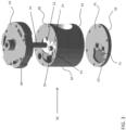
- the casing 36 includes a rotor case 60, a lower bearing housing 62 arranged adjacent a first end 64 of the rotor case 60 to form the first (lower) end 38 of the casing 36.
- an upper bearing housing 66 is arranged adjacent a second, opposite end 68 of the rotor case 60 and forms the second (upper) end 40 of the casing 36.
- the rotor case 60 includes a hollow chamber or internal cavity 70 separate from the bore 72 configured to receive the male and female rotors 22, 24.
- a first recess 74 is formed in a surface 76 of the lower bearing housing 62 adjacent the rotor case 60.
- the first recess 74 is sized, shaped, and positioned to fluidly couple the internal cavity 70 to a first end of the bore 72 housing the rotors 22, 24.
- a second recess 78 ( FIG. 6A ) may be formed in the surface 80 of the upper bearing housing 66 facing the rotor case 60.
- the second recess 78 is sized, shaped and positioned to fluidly couple the internal cavity 70 to a second, opposite end of the cavity 72 housing the rotors 22, 24.
- the first recess 74 and the second recess 78 are substantially identical in shape.
- first recess 74 and the second recess 78 have different configurations are also within the scope of the disclosure. Further, it should be understood that the depth of both the first recess 74 and the second recess 78 is less than a thickness of the lower bearing housing 62 and the upper bearing housing 66, respectively. As a result, the first and second recesses 74, 78 do not provide a means for refrigerant to escape from the casing 36.
- At least one of the first recess 74 and the second recess 78 fluidly coupling the compression pocket including the first and second rotors 22, 24 to the hollow internal chamber 82 is formed in a portion of the rotor case 60.
- the first and second recess 74, 78 are formed at the distal ends, 64, 68 of the rotor case 60 such that the lower and upper bearing housings 64, 66 define a wall adjacent of the recess 74, 78.
- the upper bearing housing 66 additionally includes hollow internal chamber 82 operably coupled to the internal cavity 70 of the rotor case 60 by a fluid passageway 84.
- At least one exit opening 86 is formed in an outer surface 88 of the upper bearing housing 66 and is arranged in fluid communication with the hollow internal chamber 82.
- the at least one exit opening 86 includes three exit openings, having a slot-like configuration.
- any suitable number of exit openings 86 is within the scope of the disclosure.
- each of the plurality of the exit openings 86 is shown having a substantially identical configuration, in other embodiment, the exit openings 86 may vary in size and shape.
- each of the exit openings 86 is arranged at a distinct location such that the plurality of exit openings 86 is distributed over the outer surface 88 of the upper bearing housing 66.
- the exit openings 86 are equidistantly spaced about a periphery of the upper bearing housing 66 such that the compressed refrigerant expelled from the exit openings 86 uniformly cools an exterior surface of the electric motor 42.
- the exit openings 86 may be formed at any location of the outer surface of the upper bearing housing.
- the compressed refrigerant is forced from the first and second recess 74, 78 into the internal cavity 70 of the rotor case 60. From the internal cavity 70, the compressed refrigerant flows through the fluid passage 84 and into the hollow internal chamber 82 formed in the upper bearing housing 66. Within the internal chamber 82, the refrigerant is distributed to each of the exit openings 86. Once discharged from the exit opening 86, the compressed refrigerant interacts with an outer surface of a portion of the motor 42, thereby cooling the motor 42.
- a compressor as described herein provides an internal discharge passage for cooling the motor 42 while minimizing the total number of components required for the rotor casing 36. By effectively utilizing the space within each component, the overall size of the compressor can be reduced.
Landscapes
- Engineering & Computer Science (AREA)
- Mechanical Engineering (AREA)
- General Engineering & Computer Science (AREA)
- Applications Or Details Of Rotary Compressors (AREA)
Claims (9)
- Kompressorgehäuse (36), das einen internen Gaskanal aufweist, umfassend:ein erstes Lagergehäuse (62), das an einem ersten Ende (38) des Gehäuses angeordnet ist;ein zweites Lagergehäuse (66), das an einem zweiten, gegenüberliegenden Ende (40) des Gehäuses angeordnet ist;ein Rotorgehäuse (60), das zwischen dem ersten Lagergehäuse und dem zweiten Lagergehäuse angeordnet ist, wobei das Rotorgehäuse eine sich axial erstreckende Bohrung (72) beinhaltet, in der eine Vielzahl von Rotoren (22, 24) aufnehmbar ist, dadurch gekennzeichnet, dass das Kompressorgehäuse fernereinen hohlen Innenraum (70), der von der Bohrung getrennt ist, wobei der hohle Innenraum (70) über mindestens eine Ausnehmung (74, 78) fluidisch mit der Bohrung gekoppelt ist; undmindestens eine Austrittsöffnung (86) beinhaltet, die in dem zweiten Lagergehäuse (66) ausgebildet ist, wobei die mindestens eine Austrittsöffnung mit dem hohlen Innenraum (70) des Rotorgehäuses wirkgekoppelt ist, wobei das zweite Lagergehäuse eine Innenkammer (82) umfasst, die in Fluidverbindung mit dem hohlen Innenraum (70) des Rotorgehäuses (60) angeordnet ist, und wobei das zweite Lagergehäuse (66) einen Fluidkanal (84) umfasst, der sich zwischen dem hohlen Innenraum (70) und der Innenkammer (82) erstreckt.
- Kompressorgehäuse (36) nach Anspruch 1, wobei mindestens eines von dem ersten Lagergehäuse (62) und dem zweiten Lagergehäuse (66) die mindestens eine Ausnehmung (74, 78) beinhaltet, die die Bohrung (72) mit dem hohlen Innenraum (70) fluidisch koppelt.
- Kompressorgehäuse (36) nach Anspruch 2, wobei das erste Lagergehäuse (62) eine erste Ausnehmung (74) und das zweite Lagergehäuse (66) eine zweite Ausnehmung (78) beinhaltet.
- Kompressorgehäuse (36) nach Anspruch 3, wobei die mindestens eine Ausnehmung (74, 78) in dem Rotorgehäuse (60) ausgebildet ist.
- Kompressorgehäuse (36) nach einem der Ansprüche 1 bis 4, wobei die mindestens eine Austrittsöffnung (86) eine Vielzahl von Austrittsöffnungen beinhaltet.
- Kompressorgehäuse (36) nach Anspruch 5, wobei jede der Vielzahl von Austrittsöffnungen (86) eine im Wesentlichen identische Konfiguration aufweist.
- Kompressorgehäuse (36) nach Anspruch 5 oder 6, wobei die Vielzahl von Austrittsöffnungen (86) über einen Umfang des zweiten Lagergehäuses (66) verteilt ist.
- Kompressorgehäuse (36) nach Anspruch 5, 6 oder 7, wobei die Vielzahl von Austrittsöffnungen (86) derart um das zweite Lagergehäuse (66) herum angeordnet ist, dass die komprimierte Kältemittelausgabe aus der Vielzahl von Austrittsöffnungen gleichmäßig verteilt ist.
- Kompressorgehäuse (36) nach einem der vorhergehenden Ansprüche, wobei die mindestens eine Austrittsöffnung (86) eine Vielzahl von Austrittsöffnungen beinhaltet und die Innenkammer (82) komprimiertes Kältemittel aus dem hohlen Innenraum (70) auf jede der Vielzahl von Austrittsöffnungen verteilt.
Applications Claiming Priority (2)
| Application Number | Priority Date | Filing Date | Title |
|---|---|---|---|
| US201762577001P | 2017-10-25 | 2017-10-25 | |
| PCT/US2018/057125 WO2019084019A1 (en) | 2017-10-25 | 2018-10-23 | INTERNAL GAS PASSAGE FOR COMPRESSOR |
Publications (3)
| Publication Number | Publication Date |
|---|---|
| EP3701150A1 EP3701150A1 (de) | 2020-09-02 |
| EP3701150B1 true EP3701150B1 (de) | 2024-05-01 |
| EP3701150B8 EP3701150B8 (de) | 2024-06-19 |
Family
ID=64267945
Family Applications (1)
| Application Number | Title | Priority Date | Filing Date |
|---|---|---|---|
| EP18800412.1A Active EP3701150B8 (de) | 2017-10-25 | 2018-10-23 | Interner abgaskanal für kompressor |
Country Status (4)
| Country | Link |
|---|---|
| US (1) | US11365735B2 (de) |
| EP (1) | EP3701150B8 (de) |
| CN (1) | CN111247342B (de) |
| WO (1) | WO2019084019A1 (de) |
Families Citing this family (1)
| Publication number | Priority date | Publication date | Assignee | Title |
|---|---|---|---|---|
| CN112780551B (zh) * | 2021-02-26 | 2025-09-16 | 珠海格力电器股份有限公司 | 转子组件、压缩机和空调 |
Citations (1)
| Publication number | Priority date | Publication date | Assignee | Title |
|---|---|---|---|---|
| US20010041280A1 (en) * | 1999-12-17 | 2001-11-15 | Hidefumi Mori | Air supply system for fuel cell |
Family Cites Families (13)
| Publication number | Priority date | Publication date | Assignee | Title |
|---|---|---|---|---|
| GB464476A (en) * | 1935-02-12 | 1937-04-16 | Milo Ab | Improvements in rotary engines |
| US3112869A (en) * | 1960-10-17 | 1963-12-03 | Willis A Aschoff | High vacuum pump |
| US3804565A (en) * | 1961-09-27 | 1974-04-16 | Laval Turbine | Screw pumps |
| US4609329A (en) * | 1985-04-05 | 1986-09-02 | Frick Company | Micro-processor control of a movable slide stop and a movable slide valve in a helical screw rotary compressor with an enconomizer inlet port |
| US5393209A (en) * | 1993-03-29 | 1995-02-28 | The United States Of America As Represented By The United States Department Of Energy | Double-ended ceramic helical-rotor expander |
| JP3957083B2 (ja) * | 1995-06-21 | 2007-08-08 | ステアリング・インダストリー・コンサルト・ゲゼルシャフト・ミット・ベシュレンクテル・ハフツング | 軸流ポンプチャンバ内で回転する一対のディスプレイスメントロータを有する真空ポンプ |
| JPH1082385A (ja) * | 1996-09-09 | 1998-03-31 | Ishikawajima Harima Heavy Ind Co Ltd | リショルム型コンプレッサのケーシング構造 |
| CN102046980B (zh) * | 2008-05-30 | 2015-10-07 | 开利公司 | 具有不对称端口的螺杆压缩机 |
| ES2570729T3 (es) * | 2008-06-24 | 2016-05-20 | Carrier Corp | Variación de relación de volumen automática para un compresor de tornillo rotatorio |
| DE102009017886A1 (de) * | 2009-04-17 | 2010-10-21 | Oerlikon Leybold Vacuum Gmbh | Schraubenvakuumpumpe |
| US20150030490A1 (en) * | 2010-07-20 | 2015-01-29 | Trane International Inc. | Bearing Housing and Assembly of a Screw Compressor |
| DE102014102390B3 (de) * | 2014-02-25 | 2015-03-26 | Leistritz Pumpen Gmbh | Schraubenspindelpumpe |
| JP6469549B2 (ja) * | 2014-09-29 | 2019-02-13 | 株式会社神戸製鋼所 | オイルフリースクリュ圧縮機 |
-
2018
- 2018-10-23 CN CN201880069614.1A patent/CN111247342B/zh active Active
- 2018-10-23 WO PCT/US2018/057125 patent/WO2019084019A1/en not_active Ceased
- 2018-10-23 EP EP18800412.1A patent/EP3701150B8/de active Active
- 2018-10-23 US US16/758,309 patent/US11365735B2/en active Active
Patent Citations (1)
| Publication number | Priority date | Publication date | Assignee | Title |
|---|---|---|---|---|
| US20010041280A1 (en) * | 1999-12-17 | 2001-11-15 | Hidefumi Mori | Air supply system for fuel cell |
Also Published As
| Publication number | Publication date |
|---|---|
| US20200256337A1 (en) | 2020-08-13 |
| US11365735B2 (en) | 2022-06-21 |
| WO2019084019A1 (en) | 2019-05-02 |
| EP3701150A1 (de) | 2020-09-02 |
| CN111247342B (zh) | 2023-03-28 |
| CN111247342A (zh) | 2020-06-05 |
| EP3701150B8 (de) | 2024-06-19 |
Similar Documents
| Publication | Publication Date | Title |
|---|---|---|
| EP3489515B1 (de) | Gegenläufiger schraubenverdichter mit störungsfreiem system | |
| EP3701151B1 (de) | Schmiermittelzufuhrkanal für kompressorhintergrund | |
| US11268512B2 (en) | Fluid machine with helically lobed rotors | |
| JP4814167B2 (ja) | 多段圧縮機 | |
| US20120014825A1 (en) | Roots type fluid machine | |
| JP6554926B2 (ja) | スクロール圧縮機 | |
| EP1846642B1 (de) | Schraubenverdichterschmierung | |
| EP3701150B1 (de) | Interner abgaskanal für kompressor | |
| EP3480468A2 (de) | Gegenläufiger schraubenkompressor mit versetztem schraubenrotor | |
| CN108930649B9 (zh) | 具有油管理系统的压缩机 | |
| JP2011069309A (ja) | スクリュー圧縮機 | |
| US20180363649A1 (en) | Scroll compressor | |
| JPH10259701A (ja) | 容積型流体機械 | |
| US6589026B2 (en) | Fluid machinery having a helical mechanism with through holes for ventilation | |
| JP2004190510A (ja) | 気体圧縮機 | |
| CN102852794B (zh) | 多气缸旋转式压缩机以及冷冻循环装置 | |
| JP5843729B2 (ja) | 気体圧縮機 | |
| KR102163622B1 (ko) | 마찰 손실을 저감한 로터리 압축기 | |
| JP5826709B2 (ja) | 気体圧縮機 | |
| KR102361320B1 (ko) | 2단 압축구조를 가지는 로터리 압축기 | |
| JP5826708B2 (ja) | 気体圧縮機 | |
| CN114060277A (zh) | 压缩机以及具有其的电器 | |
| KR20080028173A (ko) | 공기 압축기 | |
| HK1117213B (en) | Screw compressor lubrication | |
| HK1116531A1 (zh) | 螺杆式壓縮機的密封 |
Legal Events
| Date | Code | Title | Description |
|---|---|---|---|
| STAA | Information on the status of an ep patent application or granted ep patent |
Free format text: STATUS: UNKNOWN |
|
| STAA | Information on the status of an ep patent application or granted ep patent |
Free format text: STATUS: THE INTERNATIONAL PUBLICATION HAS BEEN MADE |
|
| PUAI | Public reference made under article 153(3) epc to a published international application that has entered the european phase |
Free format text: ORIGINAL CODE: 0009012 |
|
| STAA | Information on the status of an ep patent application or granted ep patent |
Free format text: STATUS: REQUEST FOR EXAMINATION WAS MADE |
|
| 17P | Request for examination filed |
Effective date: 20200506 |
|
| AK | Designated contracting states |
Kind code of ref document: A1 Designated state(s): AL AT BE BG CH CY CZ DE DK EE ES FI FR GB GR HR HU IE IS IT LI LT LU LV MC MK MT NL NO PL PT RO RS SE SI SK SM TR |
|
| AX | Request for extension of the european patent |
Extension state: BA ME |
|
| DAV | Request for validation of the european patent (deleted) | ||
| DAX | Request for extension of the european patent (deleted) | ||
| STAA | Information on the status of an ep patent application or granted ep patent |
Free format text: STATUS: EXAMINATION IS IN PROGRESS |
|
| 17Q | First examination report despatched |
Effective date: 20220309 |
|
| GRAP | Despatch of communication of intention to grant a patent |
Free format text: ORIGINAL CODE: EPIDOSNIGR1 |
|
| STAA | Information on the status of an ep patent application or granted ep patent |
Free format text: STATUS: GRANT OF PATENT IS INTENDED |
|
| INTG | Intention to grant announced |
Effective date: 20231204 |
|
| GRAS | Grant fee paid |
Free format text: ORIGINAL CODE: EPIDOSNIGR3 |
|
| GRAA | (expected) grant |
Free format text: ORIGINAL CODE: 0009210 |
|
| STAA | Information on the status of an ep patent application or granted ep patent |
Free format text: STATUS: THE PATENT HAS BEEN GRANTED |
|
| AK | Designated contracting states |
Kind code of ref document: B1 Designated state(s): AL AT BE BG CH CY CZ DE DK EE ES FI FR GB GR HR HU IE IS IT LI LT LU LV MC MK MT NL NO PL PT RO RS SE SI SK SM TR |
|
| REG | Reference to a national code |
Ref country code: GB Ref legal event code: FG4D |
|
| REG | Reference to a national code |
Ref country code: CH Ref legal event code: EP |
|
| REG | Reference to a national code |
Ref country code: DE Ref legal event code: R081 Ref document number: 602018069002 Country of ref document: DE Owner name: CARRIER CORPORATION, PALM BEACH GARDENS, US Free format text: FORMER OWNER: CARRIER CORPORATION, JUPITER, FL, US |
|
| REG | Reference to a national code |
Ref country code: IE Ref legal event code: FG4D |
|
| REG | Reference to a national code |
Ref country code: DE Ref legal event code: R096 Ref document number: 602018069002 Country of ref document: DE |
|
| REG | Reference to a national code |
Ref country code: CH Ref legal event code: PK Free format text: BERICHTIGUNG B8 |
|
| RAP4 | Party data changed (patent owner data changed or rights of a patent transferred) |
Owner name: CARRIER CORPORATION |
|
| REG | Reference to a national code |
Ref country code: LT Ref legal event code: MG9D |
|
| REG | Reference to a national code |
Ref country code: NL Ref legal event code: MP Effective date: 20240501 |
|
| PG25 | Lapsed in a contracting state [announced via postgrant information from national office to epo] |
Ref country code: IS Free format text: LAPSE BECAUSE OF FAILURE TO SUBMIT A TRANSLATION OF THE DESCRIPTION OR TO PAY THE FEE WITHIN THE PRESCRIBED TIME-LIMIT Effective date: 20240901 |
|
| PG25 | Lapsed in a contracting state [announced via postgrant information from national office to epo] |
Ref country code: BG Free format text: LAPSE BECAUSE OF FAILURE TO SUBMIT A TRANSLATION OF THE DESCRIPTION OR TO PAY THE FEE WITHIN THE PRESCRIBED TIME-LIMIT Effective date: 20240501 |
|
| PG25 | Lapsed in a contracting state [announced via postgrant information from national office to epo] |
Ref country code: FI Free format text: LAPSE BECAUSE OF FAILURE TO SUBMIT A TRANSLATION OF THE DESCRIPTION OR TO PAY THE FEE WITHIN THE PRESCRIBED TIME-LIMIT Effective date: 20240501 Ref country code: HR Free format text: LAPSE BECAUSE OF FAILURE TO SUBMIT A TRANSLATION OF THE DESCRIPTION OR TO PAY THE FEE WITHIN THE PRESCRIBED TIME-LIMIT Effective date: 20240501 |
|
| PG25 | Lapsed in a contracting state [announced via postgrant information from national office to epo] |
Ref country code: GR Free format text: LAPSE BECAUSE OF FAILURE TO SUBMIT A TRANSLATION OF THE DESCRIPTION OR TO PAY THE FEE WITHIN THE PRESCRIBED TIME-LIMIT Effective date: 20240802 |
|
| PG25 | Lapsed in a contracting state [announced via postgrant information from national office to epo] |
Ref country code: PT Free format text: LAPSE BECAUSE OF FAILURE TO SUBMIT A TRANSLATION OF THE DESCRIPTION OR TO PAY THE FEE WITHIN THE PRESCRIBED TIME-LIMIT Effective date: 20240902 |
|
| REG | Reference to a national code |
Ref country code: AT Ref legal event code: MK05 Ref document number: 1682675 Country of ref document: AT Kind code of ref document: T Effective date: 20240501 |
|
| PG25 | Lapsed in a contracting state [announced via postgrant information from national office to epo] |
Ref country code: NL Free format text: LAPSE BECAUSE OF FAILURE TO SUBMIT A TRANSLATION OF THE DESCRIPTION OR TO PAY THE FEE WITHIN THE PRESCRIBED TIME-LIMIT Effective date: 20240501 |
|
| PG25 | Lapsed in a contracting state [announced via postgrant information from national office to epo] |
Ref country code: ES Free format text: LAPSE BECAUSE OF FAILURE TO SUBMIT A TRANSLATION OF THE DESCRIPTION OR TO PAY THE FEE WITHIN THE PRESCRIBED TIME-LIMIT Effective date: 20240501 |
|
| PG25 | Lapsed in a contracting state [announced via postgrant information from national office to epo] |
Ref country code: AT Free format text: LAPSE BECAUSE OF FAILURE TO SUBMIT A TRANSLATION OF THE DESCRIPTION OR TO PAY THE FEE WITHIN THE PRESCRIBED TIME-LIMIT Effective date: 20240501 |
|
| PG25 | Lapsed in a contracting state [announced via postgrant information from national office to epo] |
Ref country code: PL Free format text: LAPSE BECAUSE OF FAILURE TO SUBMIT A TRANSLATION OF THE DESCRIPTION OR TO PAY THE FEE WITHIN THE PRESCRIBED TIME-LIMIT Effective date: 20240501 |
|
| PG25 | Lapsed in a contracting state [announced via postgrant information from national office to epo] |
Ref country code: LV Free format text: LAPSE BECAUSE OF FAILURE TO SUBMIT A TRANSLATION OF THE DESCRIPTION OR TO PAY THE FEE WITHIN THE PRESCRIBED TIME-LIMIT Effective date: 20240501 |
|
| PG25 | Lapsed in a contracting state [announced via postgrant information from national office to epo] |
Ref country code: PT Free format text: LAPSE BECAUSE OF FAILURE TO SUBMIT A TRANSLATION OF THE DESCRIPTION OR TO PAY THE FEE WITHIN THE PRESCRIBED TIME-LIMIT Effective date: 20240902 Ref country code: PL Free format text: LAPSE BECAUSE OF FAILURE TO SUBMIT A TRANSLATION OF THE DESCRIPTION OR TO PAY THE FEE WITHIN THE PRESCRIBED TIME-LIMIT Effective date: 20240501 Ref country code: NO Free format text: LAPSE BECAUSE OF FAILURE TO SUBMIT A TRANSLATION OF THE DESCRIPTION OR TO PAY THE FEE WITHIN THE PRESCRIBED TIME-LIMIT Effective date: 20240801 Ref country code: NL Free format text: LAPSE BECAUSE OF FAILURE TO SUBMIT A TRANSLATION OF THE DESCRIPTION OR TO PAY THE FEE WITHIN THE PRESCRIBED TIME-LIMIT Effective date: 20240501 Ref country code: LV Free format text: LAPSE BECAUSE OF FAILURE TO SUBMIT A TRANSLATION OF THE DESCRIPTION OR TO PAY THE FEE WITHIN THE PRESCRIBED TIME-LIMIT Effective date: 20240501 Ref country code: IS Free format text: LAPSE BECAUSE OF FAILURE TO SUBMIT A TRANSLATION OF THE DESCRIPTION OR TO PAY THE FEE WITHIN THE PRESCRIBED TIME-LIMIT Effective date: 20240901 Ref country code: HR Free format text: LAPSE BECAUSE OF FAILURE TO SUBMIT A TRANSLATION OF THE DESCRIPTION OR TO PAY THE FEE WITHIN THE PRESCRIBED TIME-LIMIT Effective date: 20240501 Ref country code: GR Free format text: LAPSE BECAUSE OF FAILURE TO SUBMIT A TRANSLATION OF THE DESCRIPTION OR TO PAY THE FEE WITHIN THE PRESCRIBED TIME-LIMIT Effective date: 20240802 Ref country code: FI Free format text: LAPSE BECAUSE OF FAILURE TO SUBMIT A TRANSLATION OF THE DESCRIPTION OR TO PAY THE FEE WITHIN THE PRESCRIBED TIME-LIMIT Effective date: 20240501 Ref country code: ES Free format text: LAPSE BECAUSE OF FAILURE TO SUBMIT A TRANSLATION OF THE DESCRIPTION OR TO PAY THE FEE WITHIN THE PRESCRIBED TIME-LIMIT Effective date: 20240501 Ref country code: BG Free format text: LAPSE BECAUSE OF FAILURE TO SUBMIT A TRANSLATION OF THE DESCRIPTION OR TO PAY THE FEE WITHIN THE PRESCRIBED TIME-LIMIT Effective date: 20240501 Ref country code: AT Free format text: LAPSE BECAUSE OF FAILURE TO SUBMIT A TRANSLATION OF THE DESCRIPTION OR TO PAY THE FEE WITHIN THE PRESCRIBED TIME-LIMIT Effective date: 20240501 Ref country code: RS Free format text: LAPSE BECAUSE OF FAILURE TO SUBMIT A TRANSLATION OF THE DESCRIPTION OR TO PAY THE FEE WITHIN THE PRESCRIBED TIME-LIMIT Effective date: 20240801 |
|
| PG25 | Lapsed in a contracting state [announced via postgrant information from national office to epo] |
Ref country code: DK Free format text: LAPSE BECAUSE OF FAILURE TO SUBMIT A TRANSLATION OF THE DESCRIPTION OR TO PAY THE FEE WITHIN THE PRESCRIBED TIME-LIMIT Effective date: 20240501 |
|
| PG25 | Lapsed in a contracting state [announced via postgrant information from national office to epo] |
Ref country code: EE Free format text: LAPSE BECAUSE OF FAILURE TO SUBMIT A TRANSLATION OF THE DESCRIPTION OR TO PAY THE FEE WITHIN THE PRESCRIBED TIME-LIMIT Effective date: 20240501 |
|
| PG25 | Lapsed in a contracting state [announced via postgrant information from national office to epo] |
Ref country code: CZ Free format text: LAPSE BECAUSE OF FAILURE TO SUBMIT A TRANSLATION OF THE DESCRIPTION OR TO PAY THE FEE WITHIN THE PRESCRIBED TIME-LIMIT Effective date: 20240501 |
|
| PG25 | Lapsed in a contracting state [announced via postgrant information from national office to epo] |
Ref country code: SK Free format text: LAPSE BECAUSE OF FAILURE TO SUBMIT A TRANSLATION OF THE DESCRIPTION OR TO PAY THE FEE WITHIN THE PRESCRIBED TIME-LIMIT Effective date: 20240501 Ref country code: RO Free format text: LAPSE BECAUSE OF FAILURE TO SUBMIT A TRANSLATION OF THE DESCRIPTION OR TO PAY THE FEE WITHIN THE PRESCRIBED TIME-LIMIT Effective date: 20240501 |
|
| PG25 | Lapsed in a contracting state [announced via postgrant information from national office to epo] |
Ref country code: SM Free format text: LAPSE BECAUSE OF FAILURE TO SUBMIT A TRANSLATION OF THE DESCRIPTION OR TO PAY THE FEE WITHIN THE PRESCRIBED TIME-LIMIT Effective date: 20240501 |
|
| PG25 | Lapsed in a contracting state [announced via postgrant information from national office to epo] |
Ref country code: SM Free format text: LAPSE BECAUSE OF FAILURE TO SUBMIT A TRANSLATION OF THE DESCRIPTION OR TO PAY THE FEE WITHIN THE PRESCRIBED TIME-LIMIT Effective date: 20240501 Ref country code: SK Free format text: LAPSE BECAUSE OF FAILURE TO SUBMIT A TRANSLATION OF THE DESCRIPTION OR TO PAY THE FEE WITHIN THE PRESCRIBED TIME-LIMIT Effective date: 20240501 Ref country code: RO Free format text: LAPSE BECAUSE OF FAILURE TO SUBMIT A TRANSLATION OF THE DESCRIPTION OR TO PAY THE FEE WITHIN THE PRESCRIBED TIME-LIMIT Effective date: 20240501 Ref country code: EE Free format text: LAPSE BECAUSE OF FAILURE TO SUBMIT A TRANSLATION OF THE DESCRIPTION OR TO PAY THE FEE WITHIN THE PRESCRIBED TIME-LIMIT Effective date: 20240501 Ref country code: DK Free format text: LAPSE BECAUSE OF FAILURE TO SUBMIT A TRANSLATION OF THE DESCRIPTION OR TO PAY THE FEE WITHIN THE PRESCRIBED TIME-LIMIT Effective date: 20240501 Ref country code: CZ Free format text: LAPSE BECAUSE OF FAILURE TO SUBMIT A TRANSLATION OF THE DESCRIPTION OR TO PAY THE FEE WITHIN THE PRESCRIBED TIME-LIMIT Effective date: 20240501 |
|
| REG | Reference to a national code |
Ref country code: DE Ref legal event code: R097 Ref document number: 602018069002 Country of ref document: DE |
|
| PG25 | Lapsed in a contracting state [announced via postgrant information from national office to epo] |
Ref country code: IT Free format text: LAPSE BECAUSE OF FAILURE TO SUBMIT A TRANSLATION OF THE DESCRIPTION OR TO PAY THE FEE WITHIN THE PRESCRIBED TIME-LIMIT Effective date: 20240501 |
|
| PLBE | No opposition filed within time limit |
Free format text: ORIGINAL CODE: 0009261 |
|
| STAA | Information on the status of an ep patent application or granted ep patent |
Free format text: STATUS: NO OPPOSITION FILED WITHIN TIME LIMIT |
|
| 26N | No opposition filed |
Effective date: 20250204 |
|
| PG25 | Lapsed in a contracting state [announced via postgrant information from national office to epo] |
Ref country code: SI Free format text: LAPSE BECAUSE OF FAILURE TO SUBMIT A TRANSLATION OF THE DESCRIPTION OR TO PAY THE FEE WITHIN THE PRESCRIBED TIME-LIMIT Effective date: 20240501 |
|
| REG | Reference to a national code |
Ref country code: CH Ref legal event code: PL |
|
| GBPC | Gb: european patent ceased through non-payment of renewal fee |
Effective date: 20241023 |
|
| PG25 | Lapsed in a contracting state [announced via postgrant information from national office to epo] |
Ref country code: MC Free format text: LAPSE BECAUSE OF FAILURE TO SUBMIT A TRANSLATION OF THE DESCRIPTION OR TO PAY THE FEE WITHIN THE PRESCRIBED TIME-LIMIT Effective date: 20240501 |
|
| PG25 | Lapsed in a contracting state [announced via postgrant information from national office to epo] |
Ref country code: GB Free format text: LAPSE BECAUSE OF NON-PAYMENT OF DUE FEES Effective date: 20241023 |
|
| PG25 | Lapsed in a contracting state [announced via postgrant information from national office to epo] |
Ref country code: LU Free format text: LAPSE BECAUSE OF NON-PAYMENT OF DUE FEES Effective date: 20241023 Ref country code: BE Free format text: LAPSE BECAUSE OF NON-PAYMENT OF DUE FEES Effective date: 20241031 |
|
| PG25 | Lapsed in a contracting state [announced via postgrant information from national office to epo] |
Ref country code: CH Free format text: LAPSE BECAUSE OF NON-PAYMENT OF DUE FEES Effective date: 20241031 |
|
| REG | Reference to a national code |
Ref country code: BE Ref legal event code: MM Effective date: 20241031 |
|
| PG25 | Lapsed in a contracting state [announced via postgrant information from national office to epo] |
Ref country code: SE Free format text: LAPSE BECAUSE OF FAILURE TO SUBMIT A TRANSLATION OF THE DESCRIPTION OR TO PAY THE FEE WITHIN THE PRESCRIBED TIME-LIMIT Effective date: 20240501 |
|
| PGFP | Annual fee paid to national office [announced via postgrant information from national office to epo] |
Ref country code: FR Payment date: 20250924 Year of fee payment: 8 |
|
| PG25 | Lapsed in a contracting state [announced via postgrant information from national office to epo] |
Ref country code: IE Free format text: LAPSE BECAUSE OF NON-PAYMENT OF DUE FEES Effective date: 20241023 |
|
| PGFP | Annual fee paid to national office [announced via postgrant information from national office to epo] |
Ref country code: DE Payment date: 20250923 Year of fee payment: 8 |
|
| PG25 | Lapsed in a contracting state [announced via postgrant information from national office to epo] |
Ref country code: CY Free format text: LAPSE BECAUSE OF FAILURE TO SUBMIT A TRANSLATION OF THE DESCRIPTION OR TO PAY THE FEE WITHIN THE PRESCRIBED TIME-LIMIT; INVALID AB INITIO Effective date: 20181023 |